EP4394914A1 - Electrode rolling device - Google Patents
Electrode rolling device Download PDFInfo
- Publication number
- EP4394914A1 EP4394914A1 EP23866598.8A EP23866598A EP4394914A1 EP 4394914 A1 EP4394914 A1 EP 4394914A1 EP 23866598 A EP23866598 A EP 23866598A EP 4394914 A1 EP4394914 A1 EP 4394914A1
- Authority
- EP
- European Patent Office
- Prior art keywords
- outer diameter
- electrode
- center portion
- coated
- rolling roller
- Prior art date
- Legal status (The legal status is an assumption and is not a legal conclusion. Google has not performed a legal analysis and makes no representation as to the accuracy of the status listed.)
- Pending
Links
Images

Classifications
-
- H—ELECTRICITY
- H01—ELECTRIC ELEMENTS
- H01M—PROCESSES OR MEANS, e.g. BATTERIES, FOR THE DIRECT CONVERSION OF CHEMICAL ENERGY INTO ELECTRICAL ENERGY
- H01M4/00—Electrodes
- H01M4/02—Electrodes composed of, or comprising, active material
- H01M4/04—Processes of manufacture in general
-
- B—PERFORMING OPERATIONS; TRANSPORTING
- B30—PRESSES
- B30B—PRESSES IN GENERAL
- B30B3/00—Presses characterised by the use of rotary pressing members, e.g. rollers, rings, discs
- B30B3/005—Roll constructions
-
- B—PERFORMING OPERATIONS; TRANSPORTING
- B30—PRESSES
- B30B—PRESSES IN GENERAL
- B30B3/00—Presses characterised by the use of rotary pressing members, e.g. rollers, rings, discs
- B30B3/04—Presses characterised by the use of rotary pressing members, e.g. rollers, rings, discs co-operating with one another, e.g. with co-operating cones
-
- B—PERFORMING OPERATIONS; TRANSPORTING
- B30—PRESSES
- B30B—PRESSES IN GENERAL
- B30B3/00—Presses characterised by the use of rotary pressing members, e.g. rollers, rings, discs
- B30B3/04—Presses characterised by the use of rotary pressing members, e.g. rollers, rings, discs co-operating with one another, e.g. with co-operating cones
- B30B3/045—Presses characterised by the use of rotary pressing members, e.g. rollers, rings, discs co-operating with one another, e.g. with co-operating cones with co-operating cones
-
- H—ELECTRICITY
- H01—ELECTRIC ELEMENTS
- H01M—PROCESSES OR MEANS, e.g. BATTERIES, FOR THE DIRECT CONVERSION OF CHEMICAL ENERGY INTO ELECTRICAL ENERGY
- H01M10/00—Secondary cells; Manufacture thereof
- H01M10/04—Construction or manufacture in general
-
- H—ELECTRICITY
- H01—ELECTRIC ELEMENTS
- H01M—PROCESSES OR MEANS, e.g. BATTERIES, FOR THE DIRECT CONVERSION OF CHEMICAL ENERGY INTO ELECTRICAL ENERGY
- H01M10/00—Secondary cells; Manufacture thereof
- H01M10/05—Accumulators with non-aqueous electrolyte
- H01M10/058—Construction or manufacture
- H01M10/0587—Construction or manufacture of accumulators having only wound construction elements, i.e. wound positive electrodes, wound negative electrodes and wound separators
-
- H—ELECTRICITY
- H01—ELECTRIC ELEMENTS
- H01M—PROCESSES OR MEANS, e.g. BATTERIES, FOR THE DIRECT CONVERSION OF CHEMICAL ENERGY INTO ELECTRICAL ENERGY
- H01M4/00—Electrodes
- H01M4/02—Electrodes composed of, or comprising, active material
- H01M4/04—Processes of manufacture in general
- H01M4/0402—Methods of deposition of the material
- H01M4/0404—Methods of deposition of the material by coating on electrode collectors
-
- H—ELECTRICITY
- H01—ELECTRIC ELEMENTS
- H01M—PROCESSES OR MEANS, e.g. BATTERIES, FOR THE DIRECT CONVERSION OF CHEMICAL ENERGY INTO ELECTRICAL ENERGY
- H01M4/00—Electrodes
- H01M4/02—Electrodes composed of, or comprising, active material
- H01M4/13—Electrodes for accumulators with non-aqueous electrolyte, e.g. for lithium-accumulators; Processes of manufacture thereof
- H01M4/139—Processes of manufacture
-
- B—PERFORMING OPERATIONS; TRANSPORTING
- B21—MECHANICAL METAL-WORKING WITHOUT ESSENTIALLY REMOVING MATERIAL; PUNCHING METAL
- B21B—ROLLING OF METAL
- B21B2267/00—Roll parameters
- B21B2267/02—Roll dimensions
- B21B2267/06—Roll diameter
-
- B—PERFORMING OPERATIONS; TRANSPORTING
- B21—MECHANICAL METAL-WORKING WITHOUT ESSENTIALLY REMOVING MATERIAL; PUNCHING METAL
- B21B—ROLLING OF METAL
- B21B27/00—Rolls, roll alloys or roll fabrication; Lubricating, cooling or heating rolls while in use
- B21B27/02—Shape or construction of rolls
- B21B27/021—Rolls for sheets or strips
-
- H—ELECTRICITY
- H01—ELECTRIC ELEMENTS
- H01M—PROCESSES OR MEANS, e.g. BATTERIES, FOR THE DIRECT CONVERSION OF CHEMICAL ENERGY INTO ELECTRICAL ENERGY
- H01M4/00—Electrodes
- H01M4/02—Electrodes composed of, or comprising, active material
- H01M4/04—Processes of manufacture in general
- H01M4/043—Processes of manufacture in general involving compressing or compaction
- H01M4/0435—Rolling or calendering
-
- Y—GENERAL TAGGING OF NEW TECHNOLOGICAL DEVELOPMENTS; GENERAL TAGGING OF CROSS-SECTIONAL TECHNOLOGIES SPANNING OVER SEVERAL SECTIONS OF THE IPC; TECHNICAL SUBJECTS COVERED BY FORMER USPC CROSS-REFERENCE ART COLLECTIONS [XRACs] AND DIGESTS
- Y02—TECHNOLOGIES OR APPLICATIONS FOR MITIGATION OR ADAPTATION AGAINST CLIMATE CHANGE
- Y02E—REDUCTION OF GREENHOUSE GAS [GHG] EMISSIONS, RELATED TO ENERGY GENERATION, TRANSMISSION OR DISTRIBUTION
- Y02E60/00—Enabling technologies; Technologies with a potential or indirect contribution to GHG emissions mitigation
- Y02E60/10—Energy storage using batteries
Definitions
- the manufacturing process of these secondary batteries is roughly divided into three stages: electrode process, assembly process, and formation process.
- the electrode process is further divided into active material mixing process, electrode coating process, rolling process, slitting process, winding process, etc.
- the related art electrode rolling apparatus can roll the non-coated portion 22 of the electrode 20 only with the first end portion 12 having a larger outer diameter, and the second end portion 13 cannot be used for rolling the non-coated portion 22. Therefore, when the rolling roll 10 is replaced due to wear of the first end portion 12, the second end portion 13 must also be discarded. As a result, there is a costly economic problem for rolling the non-coated portion 22, and efforts are needed to improve the situation.
- Each of tapered surfaces of the first end portion and the second end portion may include a curved tapered surface and a linear tapered surface extending from the curved tapered surface.
- the first end portion and the second end portion may have same or different taper angles.
- the taper angles of the first end portion and the second end portion may be from 20 to 30 degrees.
- the first rolling roller and the second rolling roller may be made of the same or different materials, the materials being metals or polymers.
- the insulating coating portion may comprise at least one type selected from a group consisting of an insulating polymer material and an insulating ceramic material.
- the first rolling roller or the second rolling roller may be made of metal, and the insulating coating portion may comprise an insulating polymer material.
- a material of the first rolling roller or second rolling roller may be a polymer, and the insulating coating portion may comprise an insulating ceramic material.
- An outer peripheral surface of at least one of the first center portion, the first end portion, the second center portion, and the second end portion may be formed with alternating grooves and protrusions for forming a plurality of corrugations in the non-coated portion thereof, parallel to each other from the coated portion toward an end of the non-coated portion.
- Each of the grooves and protrusions may have a triangle-like shape or a semicircle-like shape in cross-section.
- the material of the first rolling roller and the second rolling roller, the ratio of the first outer diameter to the second outer diameter, the ratio of the second outer diameter to the first outer diameter, or the ratio of the length of the first center portion and the second center portion can be easily changed according to the material of the insulating coating portion, the widthwise length of the non-coated portion, and the like, so that various types of electrodes can be manufactured.
- the second rolling roller 120 may include a second center portion 121 and a second end portion 122 located at one end of the second center portion 121, and the second center portion 121 and the second end portion 122 may be integral, that is, the second end portion 122 may extend from the first end portion of the second center portion 121.
- the second rolling roller 120 may have the second end portion 122 machined in a further process relative to the second center portion 121.
- the second center portion 121 and the second end portion 122 may be manufactured separately, and the second center portion 121 and the second end portion 122 may be joined together in a further process, and the second rolling roller 120 may be manufactured in a variety of ways.
- first rolling roller 110 and the second rolling roller 120 may be integral, and the first-second outer diameter (r1-2) of the first center portion and the second-second outer diameter (r2-2) of the second center portion may be the same.
- the electrode rolling apparatus 100 of the present invention has a very economical effect because both the first rolling roller 110 and the second rolling roller 120 can be used for rolling the non-coated portion 22 of the electrode 20.
- the non-coated portion 22 can be rolled to a level equivalent to the coated portion 21 by selecting the first rolling roller 110 or the second rolling roller 120 suitable for the shape and material of the electrode 20.
- An outer surface of the first center portion 111 may be one extending from the first end portion 112 to the second center portion 121, and an outer surface of the second center portion 121 may be one extending from the second end portion 122 to the first center portion 111.
- the first-first outer diameter (r1-1) may be smaller than the first-second outer diameter (r1-2) whereas the second-first outer diameter (r2-1) may be smaller than the second-second outer diameter (r2-2).
- the first-first outer diameter (r1-1) may be larger than the first-second outer diameter (r1-2) whereas the second-first outer diameter (r2-1) may be larger than the second-second outer diameter (r2-2).
- first-second outer diameter (r1-2) with respect to the first-first outer diameter (r1-1) to may be 0.8 to 0.99 times or 1.01 to 1.2 times
- second-second outer diameter (r2-2) with respect to the second-first outer diameter (r2-1) to may be 0.8 to 0.99 times or 1.01 to 1.2 times.
- the length L1 of the first center portion and the length L2 of the second center portion may be the same or different from each other.
- the ratio of the length L1 of the first center portion to the length L2 of the second center portion may be 3:5 to 5:3, more preferably 3:4 to 4:3.
- the length (L1) of the first center portion and the length (L2) of the second center portion may be the same, in which case the first-first outer diameter (r1-1) and the second-first outer diameter (r2-1) may be the same or different from each other.
- the length (L1) of the first center portion and the length (L2) of the second center portion may be different from each other, in which case the first-first outer diameter (r1-1) and the second-second outer diameter (r2-2) may be the same or different from each other.
- the first end portion 112 may be tapered in shape with a gradually decreasing outer diameter from the first center portion 111 toward the end whereas the second end portion 122 may be tapered in shape with a gradually decreasing outer diameter from the second center portion 121 toward the end.
- first end portion 112 and second end portion 122 may have a tapered angle, and the tapered angle of the first end portion 112 and the tapered angle of the second end portion 122 may be the same or different from each other.
- the taper angle of the first end portion 112 and the taper angle of the second end portion 122 may be 20 to 30 degrees.
- the first-first outer diameter (r1-1) may be larger than the first-second outer diameter (r1-2), and the second-first outer diameter (r2-1) may be larger than the second-second outer diameter (r2-2).
- the length (L1) of the first center portion may be the same as the length (L2) of the second center portion, and the first-first outer diameter (r1 -1) and the second-first outer diameter (r2-1) may be the same as each other.
- the electrode rolling apparatus 100 shown in FIGS. 3 and 4 may have a configuration in which the first rolling roller 110 and the second rolling roller 120 are symmetrical.
- FIGS. 5 and 6 show that the first end portion 112 and the second end portion 122 are located at the boundary of the insulating coating portion 23 and the non-insulating coating portion 24 of the electrode 20, this does not indicate that the first rolling roller 110 and the second rolling roller 120 roll the non-coated portion 22 of the electrode 20 simultaneously, but rather, that each of the first rolling roller 110 and the second rolling roller 120 rolls the non-coated portion 22 of the electrode 20.
- first rolling roller 110 and the second rolling roller 120 are made of the same material, the first rolling roller 110 and the second rolling roller 120 may be integrally formed.
Landscapes
- Engineering & Computer Science (AREA)
- Chemical & Material Sciences (AREA)
- Manufacturing & Machinery (AREA)
- Chemical Kinetics & Catalysis (AREA)
- Electrochemistry (AREA)
- General Chemical & Material Sciences (AREA)
- Mechanical Engineering (AREA)
- Materials Engineering (AREA)
- Battery Electrode And Active Subsutance (AREA)
- Laminated Bodies (AREA)
Abstract
Description
- The present application claims the benefit and priority to
Korean Patent Application No. 10-2022-0126836, filed October 5, 2022 - The present invention relates to an electrode rolling apparatus, and more particularly to an electrode rolling apparatus for applying pressure to a non-coated portion of an electrode.
- Secondary batteries are not only used as an energy source for mobile devices, but also as a power source for electric vehicles (EVs) and hybrid electric vehicles (HEVs), and are increasingly being used as a backup power source for grid-connected electricity.
- The manufacturing process of these secondary batteries is roughly divided into three stages: electrode process, assembly process, and formation process. The electrode process is further divided into active material mixing process, electrode coating process, rolling process, slitting process, winding process, etc.
- Among them, the rolling process is a process in which the electrode sheet after the coating process of the electrode active material is reduced in thickness to increase the capacity density and increase the adhesion and compactness between the electrode collector and the electrode active material contained in the electrode active material, and the electrode sheet is compressed to the desired thickness and density by passing it between two rolling rollers heated to a high temperature.
- In such a rolling process, the thickness of the electrode sheet is determined by the rolling gap between the two rolling rollers. In such case, the rolling gap is calculated by manipulating a drive portion that controls the up and down positions of the rolling rollers to compress and roll the electrode to the desired thickness, wherein the rolling roller of one of the two rolling rollers is generally fixed, and the electrode is compressed and rolled based on the rolling gap calculated by adjusting the position of the other rolling roller with the drive portion.
- However, when the electrode sheet is rolled by a rolling roller, little pressure is applied to the non-coated portion of the electrode sheet compared to the coated portion, which is the area where the electrode active material is coated, resulting in swell or wrinkles in the non-coated portion due to the difference in the expansion rate between the coated and non-coated portions.
- These swell and wrinkles lead to meandering and severe dimensional degradation of the fabric in the winding process, which is performed after the rolling process, and consequently to poor quality electrodes for secondary batteries.
- Therefore, an additional process of rolling the non-coated portion after rolling the electrode sheet is required.
-
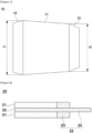
FIG. 1 is a cross-sectional view illustrating a related-art electrode rolling apparatus for rolling a non-coated portion. The related-art electrode rolling apparatus includes arolling roll 10, which includes acenter portion 11, afirst end portion 12, and asecond end portion 13. Here, the electrode rolling apparatus has an outer surface of thecenter portion 11 extending from thefirst end portion 12 to thesecond end portion 13, and a first outer diameter (r1) of thecenter portion 11 connected with thefirst end portion 12 is larger than a second outer diameter (r2) of thecenter portion 11 connected with thesecond end portion 13. With reference toFIG. 2 , thenon-coated portion 22 of theelectrode 20 includes aninsulating coating portion 23 and anon-insulating coating portion 24, and thefirst end portion 12 is located adjacent to a boundary between theinsulating coating portion 23 and thenon-insulating coating portion 24 of theelectrode 20, and pressure is applied to the insulatingcoating portion 23 and thenon-insulating coating portion 24. Since the first outer diameter r1 is larger than the second outer diameter r2, pressure can be applied uniformly even if there is a difference in the thickness of the insulatingcoating portion 23 and thenon-insulating coating portion 24, thereby reducing the variance in the expansion rate. - However, the related art electrode rolling apparatus can roll the
non-coated portion 22 of theelectrode 20 only with thefirst end portion 12 having a larger outer diameter, and thesecond end portion 13 cannot be used for rolling the non-coatedportion 22. Therefore, when therolling roll 10 is replaced due to wear of thefirst end portion 12, thesecond end portion 13 must also be discarded. As a result, there is a costly economic problem for rolling the non-coatedportion 22, and efforts are needed to improve the situation. -
-
Korean Laid-Open Patent No. 10-2019-0059210 -
Korean Laid-Open Patent No. 10-2022-0067239 - The present invention aims to provide an electrode rolling apparatus in which both a first rolling roller and a second rolling roller can be used for rolling a non-coated portion.
- To achieve the above objectives,
the present invention provides an electrode rolling apparatus for applying pressure to a non-coated portion of an electrode comprising a coated portion coated with an electrode active material and a non-coated portion not coated with an electrode active material, the non-coated portion comprising an insulating coating portion and a non-insulating coating portion, the electrode rolling apparatus comprising: a first rolling roller; and a second rolling roller, wherein the first rolling roller includes a first center portion and a first end portion located at one end of the first center portion in a longitudinal direction, wherein the second rolling roller includes a second center portion and a second end portion located at one end of the second center portion in a longitudinal direction, wherein other end surface of the first center portion and other end surface of the second center portion are in contact with each other, wherein a first-first outer diameter of the first center portion connected to the first end portion is different from a first-second outer diameter of the first center portion abutting the other end surface of the second center portion, wherein a second-first outer diameter of the second center portion connected to the second end portion is different from a second-second outer diameter of the second center portion abutting the other end surface of the first center portion, and wherein the first-second outer diameter and second-second outer diameter are the same, and wherein the first end portion or second end portion is adjacent to a boundary of the insulating coating portion and the non-insulating coating portion. - The first-first outer diameter may be smaller than the first-second outer diameter and the second-first outer diameter may be smaller than the second-second outer diameter, or wherein the first-first outer diameter may be larger than the first-second outer diameter and the second-first outer diameter may be larger than the second-second outer diameter.
- A length of the first center portion and the a length of the second center portion may be the same or different from each other.
- The length of the first center portion and the length of the second center portion may be the same, and the first-first outer diameter and the second-first outer diameter may be the same.
- The length of the first center portion and the length of the second center portion may be different from each other, and the first-first outer diameter and the second-first outer diameter may be the same or different from each other.
- The length ratio of the first center portion and the second center portion may be from 3:5 to 5:3.
- The first-second outer diameter with respect to the first-first outer diameter may be 0.8 to 0.99 times or 1.01 to 1.2 times, and the second-second outer diameter with respect to the second-first outer diameter is 0.8 to 0.99 times may be 1.01 to 1.2 times
- The first end portion may be tapered in shape with a gradually decreasing outer diameter from the first center portion toward an end thereof, and the second end portion may be tapered in shape with a gradually decreasing outer diameter from the second center portion toward an end thereof.
- Each of tapered surfaces of the first end portion and the second end portion may include a curved tapered surface and a linear tapered surface extending from the curved tapered surface.
- The first end portion and the second end portion may have same or different taper angles.
- The taper angles of the first end portion and the second end portion may be from 20 to 30 degrees.
- The first rolling roller and the second rolling roller may be made of the same or different materials, the materials being metals or polymers.
- The insulating coating portion may comprise at least one type selected from a group consisting of an insulating polymer material and an insulating ceramic material.
- The first rolling roller or the second rolling roller may be made of metal, and the insulating coating portion may comprise an insulating polymer material.
- A material of the first rolling roller or second rolling roller may be a polymer, and the insulating coating portion may comprise an insulating ceramic material.
- An outer peripheral surface of at least one of the first center portion, the first end portion, the second center portion, and the second end portion may be formed with alternating grooves and protrusions for forming a plurality of corrugations in the non-coated portion thereof, parallel to each other from the coated portion toward an end of the non-coated portion.
- Each of the grooves and protrusions may have a triangle-like shape or a semicircle-like shape in cross-section.
- In the electrode rolling apparatus of the present invention, not only the first rolling roller but also the second rolling roller can be used to roll the non-coated portion of the electrode. Specifically, even if the first rolling roller is worn out due to constant rolling of the non-coated portion, the second rolling roller can be used to roll the non-coated portion, which can be economically effective because there is no wasted configuration.
- Furthermore, the material of the first rolling roller and the second rolling roller, the ratio of the first outer diameter to the second outer diameter, the ratio of the second outer diameter to the first outer diameter, or the ratio of the length of the first center portion and the second center portion can be easily changed according to the material of the insulating coating portion, the widthwise length of the non-coated portion, and the like, so that various types of electrodes can be manufactured.
-
-
FIG. 1 is a cross-sectional view of a related-art electrode rolling apparatus. -
FIG. 2 is a cross-sectional view of an electrode. -
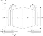
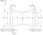
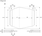
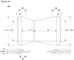
FIGS. 3 to 6 are cross-sectional views illustrating an electrode rolling apparatus used for the non-coated portion of an electrode, according to one embodiment of the present invention. -
FIG. 7 is a photograph of an electrode in which a non-coated portion has been rolled using an electrode rolling apparatus according to one embodiment of the present invention. - The present invention is hereinafter described in detail, with reference to the accompanying drawings, so as to facilitate the practice of one having ordinary skill in the art to which the present invention belongs. However, the present invention may be implemented in many different forms and is not limited to the embodiments described herein.
- In order to clearly illustrate the present invention, parts not pertinent to the description have been omitted, and identical or similar components are designated by the same reference numerals throughout the specification.
- Furthermore, the terms and words used in this specification and the claims of the patent are not to be construed in their ordinary or dictionary sense, but are to be construed with a meaning and concept consistent with the technical idea of the present invention, based on the principle that the inventor may properly define the concept of a term to best describe his invention.
-
FIG. 2 is a side cross-sectional view of anelectrode 20 to be rolled by anelectrode rolling apparatus 100 of the present invention. - Referring to
FIG. 2 , theelectrode 20 includes a coatedportion 21 having an electrode active material applied to a surface of each of two sides of a square plate-shaped collector. The portion which is not coated with the electrode active material is anon-coated portion 22, and the non-coatedportion 22 may be the collector. At the boundary of thenon-coated portion 22 and the coatedportion 21, aninsulating coating portion 23 is provided. Specifically, theinsulating coating portion 23 may be positioned such that a top or bottom surface thereof abuts the non-coatedportion 22 and a side surface thereof abuts the coatedportion 21. The portion where theinsulating coating portion 23 is not formed on thenon-coated portion 22 is thenon-insulating coating portion 24, and the non-coatedportion 22 may comprise the insulatingcoating portion 23 and thenon-insulating coating portion 24. Thus, thenon-insulating coating portion 24 may be a collector. - Furthermore, as shown in
FIG. 2 , in this embodiment, the height of the insulatingcoating portion 23 when bonded to the surface of the coatedportion 21 may be configured to be equal to or slightly lower than the height of the coatedportion 21. - The present invention is directed to an electrode rolling apparatus for applying pressure to a non-coated portion 22 of an electrode 20 including a coated portion 21 coated with an electrode active material and a non-coated portion 22 not coated with an electrode active material, the non-coated portion 22 including an insulating coating portion 23 and a non-insulating coating portion 24, wherein the electrode rolling apparatus 100 includes a first rolling roller 110; and a second rolling roller 120, wherein the first rolling roller 110 includes a first center portion 111 and a first end portion 112 located at one end of the first center portion in a longitudinal direction, wherein the second rolling roller 120 includes a second center portion 121 and a second end portion 122 located at one end of the second center portion in a longitudinal direction, wherein other end surface of the first center portion 111 and other end surface of the second center portion 121 are in contact with each other, wherein a first-first outer diameter (r1 - 1) of the first center portion 111 connected with the first end portion 112 differs from a first-second outer diameter (r1-2) of the first center portion 111 abutting the other end of the second center portion 121, wherein a second-first outer diameter (r2-1) of the second center portion 121 connected with the second end portion 122 differs from a second-second outer diameter (r2-2) of the second center portion 121 facing the other end of the first center portion 111, wherein the first-second outer diameter (r1-2) and the second-second outer diameter (r2-2) are the same, and wherein the first end portion 112 or the second end portion 122 is adjacent to a boundary between the insulating coating portion 23 and a non-insulating coating portion 24.
- The
first rolling roller 110 may include afirst center portion 111 and afirst end portion 112 located at one end of thefirst center portion 111, and thefirst center portion 111 and thefirst end portion 112 may be integral, that is, thefirst end portion 112 may extend from the first end portion of thefirst center portion 111. In one example, thefirst rolling roller 110 may have thefirst end portion 112 machined in a further process relative to thefirst center portion 111. Alternatively, and without limitation, thefirst center portion 111 and thefirst end portion 112 may be manufactured separately, and thefirst center portion 111 and thefirst end portion 112 may be joined together in a further process, and thefirst rolling roller 110 may be manufactured in various ways. - The
second rolling roller 120 may include asecond center portion 121 and asecond end portion 122 located at one end of thesecond center portion 121, and thesecond center portion 121 and thesecond end portion 122 may be integral, that is, thesecond end portion 122 may extend from the first end portion of thesecond center portion 121. In one example, thesecond rolling roller 120 may have thesecond end portion 122 machined in a further process relative to thesecond center portion 121. Alternatively, and without limitation, thesecond center portion 121 and thesecond end portion 122 may be manufactured separately, and thesecond center portion 121 and thesecond end portion 122 may be joined together in a further process, and thesecond rolling roller 120 may be manufactured in a variety of ways. - Furthermore, the other end surface of the
first center portion 111 and the other end surface of thesecond center portion 121 may be in contact with each other. Therefore, thefirst rolling roller 110 and thesecond rolling roller 120 may be integral, and the first-second outer diameter (r1-2) of the first center portion and the second-second outer diameter (r2-2) of the second center portion may be the same. - The
electrode rolling apparatus 100 of the present invention has a very economical effect because both thefirst rolling roller 110 and thesecond rolling roller 120 can be used for rolling thenon-coated portion 22 of theelectrode 20. - In the present invention, the meaning that the
first rolling roller 110 and thesecond rolling roller 120 can roll thenon-coated portion 22 of theelectrode 20 is not that thefirst rolling roller 110 and thesecond rolling roller 120 roll thenon-coated portion 22 of theelectrode 20 at the same time, but is meant that thefirst rolling roller 110 and thesecond rolling roller 120 each roll thenon-coated portion 22 of theelectrode 20. More specifically, thefirst rolling roller 110 can be used to roll thenon-coated portion 22 of theelectrode 20 first so that, when thefirst rolling roller 110 becomes unusable due to wear or the like, thesecond rolling roller 120 can be used to roll thenon-coated portion 22 of theelectrode 20. Alternatively, by manufacturing thefirst rolling roller 110 and thesecond rolling roller 120 with different shapes and materials, thenon-coated portion 22 can be rolled to a level equivalent to the coatedportion 21 by selecting thefirst rolling roller 110 or thesecond rolling roller 120 suitable for the shape and material of theelectrode 20. - An outer surface of the
first center portion 111 may be one extending from thefirst end portion 112 to thesecond center portion 121, and an outer surface of thesecond center portion 121 may be one extending from thesecond end portion 122 to thefirst center portion 111. - The first-first outer diameter (r1-1) may be smaller than the first-second outer diameter (r1-2) whereas the second-first outer diameter (r2-1) may be smaller than the second-second outer diameter (r2-2). Alternatively, the first-first outer diameter (r1-1) may be larger than the first-second outer diameter (r1-2) whereas the second-first outer diameter (r2-1) may be larger than the second-second outer diameter (r2-2).
- Further, the first-second outer diameter (r1-2) with respect to the first-first outer diameter (r1-1) to may be 0.8 to 0.99 times or 1.01 to 1.2 times whereas the second-second outer diameter (r2-2) with respect to the second-first outer diameter (r2-1) to may be 0.8 to 0.99 times or 1.01 to 1.2 times.
- The length L1 of the first center portion and the length L2 of the second center portion may be the same or different from each other. Preferably, the ratio of the length L1 of the first center portion to the length L2 of the second center portion may be 3:5 to 5:3, more preferably 3:4 to 4:3.
- The length (L1) of the first center portion and the length (L2) of the second center portion may be the same, in which case the first-first outer diameter (r1-1) and the second-first outer diameter (r2-1) may be the same or different from each other.
- The length (L1) of the first center portion and the length (L2) of the second center portion may be different from each other, in which case the first-first outer diameter (r1-1) and the second-second outer diameter (r2-2) may be the same or different from each other.
- The
first end portion 112 may be tapered in shape with a gradually decreasing outer diameter from thefirst center portion 111 toward the end whereas thesecond end portion 122 may be tapered in shape with a gradually decreasing outer diameter from thesecond center portion 121 toward the end. - Furthermore, the tapered surfaces of the
first end portion 112 and thesecond end portion 122 may include a curved tapered surface R and a linear tapered surface L extending from the curved tapered surface R. If the tapered surface is formed only with a linear tapered surface L, a break may occur when rolling thenon-coated portion 22 of theelectrode 20. Therefore, by curving the tapered surface to constitute a curved tapered surface R, thenon-coated portion 22 can be rolled without damaging theelectrode 20. - Accordingly, the
first end portion 112 andsecond end portion 122 may have a tapered angle, and the tapered angle of thefirst end portion 112 and the tapered angle of thesecond end portion 122 may be the same or different from each other. In one embodiment, the taper angle of thefirst end portion 112 and the taper angle of thesecond end portion 122 may be 20 to 30 degrees. - The
electrode rolling apparatus 100 according to the present invention can roll thenon-coated portion 22 of theelectrode 20 with thefirst rolling roller 110 or thesecond rolling roller 120, so that thefirst end portion 112 or thesecond end portion 122 can be adjacent to the boundary of the coatedportion 21 and thenon-coated portion 22. Preferably, it may be adjacent to the boundary of the insulatingcoating portion 23 and thenon-insulating coating portion 24. -
FIGS. 3 and4 illustrate anelectrode rolling apparatus 100 according to one embodiment of the present invention. - Referring to
FIG. 3 , the first-first outer diameter (r1-1) may be smaller than the first-second outer diameter (r1-2), and the second-first outer diameter (r2-1) may be smaller than the second-second outer diameter (r2-2). Further, the length (L1) of the first center portion may be the same as the length (L2) of the second center portion, and the first-first outer diameter (r1 -1) and the second-first outer diameter (r2-1) may be the same as each other. - Referring to
FIG. 4 , the first-first outer diameter (r1-1) may be larger than the first-second outer diameter (r1-2), and the second-first outer diameter (r2-1) may be larger than the second-second outer diameter (r2-2). Further, the length (L1) of the first center portion may be the same as the length (L2) of the second center portion, and the first-first outer diameter (r1 -1) and the second-first outer diameter (r2-1) may be the same as each other. - That is, the
electrode rolling apparatus 100 shown inFIGS. 3 and4 may have a configuration in which thefirst rolling roller 110 and thesecond rolling roller 120 are symmetrical. - The
coated portion 21 of theelectrode 20 may have the same or different widths of an electrode active material coated on the top surface (tab) and the bottom surface. Accordingly, the widths of the top surface and the bottom surface of thenon-coated portion 22 formed accordingly may be the same or different. - The
electrode rolling apparatus 100 shown inFIGS. 3 and4 according to one embodiment of the present invention may have a symmetrical shape of thefirst rolling roller 110 and thesecond rolling roller 120, so that it can preferably be used for rolling electrodes having the same width on the upper and lower surfaces of thenon-coated portion 22. In other words, in theelectrode rolling apparatus 100 shown inFIGS. 3 and4 , both thefirst rolling roller 110 and thesecond rolling roller 120 can be used for rolling thenon-coated portion 22 of theelectrode 20, and even if thefirst rolling roller 110 is worn, thenon-coated portion 22 can be rolled using thesecond rolling roller 120. Furthermore, theelectrode rolling apparatus 100 shown inFIGS. 3 and4 above can have an equivalent rolling effect of thenon-coated portion 22. - Although
FIGS. 3 and4 show that thefirst end portion 112 and thesecond end portion 122 are located at the boundary of the insulatingcoating portion 23 and thenon-insulating coating portion 24 of theelectrode 20, this does not indicate that thefirst rolling roller 110 and thesecond rolling roller 120 roll thenon-coated portion 22 of theelectrode 20 simultaneously, but rather that each of thefirst rolling roller 110 and thesecond rolling roller 120 rolls thenon-coated portion 22 of theelectrode 20. -
FIGS. 5 and6 illustrate anelectrode rolling apparatus 100 according to one embodiment of the present invention. - Referring to
FIG. 5 , the first-first outer diameter (r1-1) may be smaller than the first-second outer diameter (r1-2) whereas the second-first outer diameter (r2-1) may be smaller than the second-second outer diameter (r2-2). Further, the length L1 of the first center portion may be different from the length L2 of the second center portion, and the first-first outer diameter (r1-1) and the second-first outer diameter (r2-1) may be the same as each other. - Referring to
FIG. 6 , the first-first outer diameter (r1-1) may be larger than the first-second outer diameter (r1-2) whereas the second-first outer diameter (r2-1) may be larger than the second-second outer diameter (r2-2). Further, the length L1 of the first center portion may be different from the length L2 of the second center portion, and the first-first outer diameter (r1-1) and the second-first outer diameter (r2-1) may be the same as each other. - That is, the
electrode rolling apparatus 100 shown inFIGS. 5 and6 may have a configuration in which thefirst rolling roller 110 and thesecond rolling roller 120 are asymmetrical. - The
electrode rolling apparatus 100 shown inFIGS. 5 and6 according to one embodiment of the present invention has a configuration in which thefirst rolling roller 110 and thesecond rolling roller 120 are asymmetrical, so that it can preferably be used for rolling electrodes having different widths of the upper and lower surfaces of thenon-coated portion 22. In other words, both thefirst rolling roller 110 and thesecond rolling roller 120 of theelectrode rolling apparatus 100 shown inFIGS. 5 and6 can be used for rolling thenon-coated portion 22 of theelectrode 20. - The
electrode rolling apparatus 100 inFIGS. 5 and6 illustrates that the length L1 of the first center portion is shorter than the length L2 of the second center portion. Also,FIGS. 5 and6 illustrate that the top surface (tab) of thenon-coated portion 22 is narrower than the bottom surface. Therefore, the top surface (tab) of the narrowernon-coated portion 22 can be located on thefirst rolling roller 110, and the bottom surface (bottom) of the widernon-coated portion 22 can be located on thesecond rolling roller 120. - In other words, the
electrode rolling apparatus 100 according to one embodiment of the present invention is capable of selecting a rolling roller that can roll according to the shape of theelectrode 20, so that both thefirst rolling roller 110 and thesecond rolling roller 120 can be used for rolling theelectrode 20. - Although
FIGS. 5 and6 show that thefirst end portion 112 and thesecond end portion 122 are located at the boundary of the insulatingcoating portion 23 and thenon-insulating coating portion 24 of theelectrode 20, this does not indicate that thefirst rolling roller 110 and thesecond rolling roller 120 roll thenon-coated portion 22 of theelectrode 20 simultaneously, but rather, that each of thefirst rolling roller 110 and thesecond rolling roller 120 rolls thenon-coated portion 22 of theelectrode 20. - The insulating
coating portion 23 may comprise at least one type selected from a group consisting of an insulating polymer material and an insulating ceramic material. The insulating polymer material may include at least one type selected from a group consisting of polyvinylidene fluoride, polyimide, polyethylene terephthalate, polyurethane, polyacrylate, epoxy, and silicone, although the type is not particularly limited thereto and those used in the industry may be utilized therefor. The insulating ceramic material may comprise a mixture of at least one type selected from a group consisting of aluminum oxide, silicon oxide, silicon nitride, iron oxide, and glass with an insulating polymer, although the type is not particularly limited thereto and those used in the industry may be utilized therefor. - The
first rolling roller 110 and second rollingroller 120 may be made of the same or different materials, and the materials may be metals or polymers. The metal may comprise at least one oxide selected from a group consisting of aluminum, tin and zinc, and may preferably comprise aluminum. The polymer may comprise at least one species selected from a group consisting of polyetheretherketone, polyolefin resin, polyethylene terephthalate, polybutylene terephthalate, polyacetal, polyamide, polycarbonate, polyimide, polyethersulfone, polyphenylene oxide, polyphenylene sulfide, and polyethylene naphthalene, and may preferably comprise polyetheretherketone. - If the
first rolling roller 110 and thesecond rolling roller 120 are made of the same material, thefirst rolling roller 110 and thesecond rolling roller 120 may be integrally formed. - Depending on the type of the material forming the insulating
coating portion 23, the material of thefirst rolling roller 110 and thesecond rolling roller 120 can be determined. In one embodiment, if the material forming the insulatingcoating portion 23 is an insulating ceramic material, the material of thefirst rolling roller 110 or thesecond rolling roller 120 that rolls thenon-coated portion 22 of theelectrode 20 may be a polymer. If the material is metal, both the ceramic and the metal have high strength, which can lead to rapid wear of thefirst end portion 112 or thesecond end portion 122 of the metal material in contact with the ceramic. In another embodiment, if the material forming the insulatingcoating portion 23 is an insulating polymer material, the material of thefirst rolling roller 110 or thesecond rolling roller 120 that rolls thenon-coated portion 22 of theelectrode 20 may be metal. If the material is a polymer, both the insulating polymer material and the polymer may have low strength, and the rolling of thenon-coated portion 22 may not be performed properly. - Furthermore, the
electrode rolling apparatus 100 may have alternating grooves and protrusions formed on the peripheral surface of at least one of thefirst center portion 111, thefirst end portion 112, thesecond center portion 121, and thesecond end portion 122 for forming a plurality of corrugations parallel to thenon-coated portion 22, from the coatedportion 21 toward the end of thenon-coated portion 22. The grooves and protrusions may be triangular-like or semicircular-like in cross-section. - The
electrode rolling apparatus 100 of the present invention can not only roll thenon-coated portion 22 of theelectrode 20 with thefirst rolling roller 110, but can also roll thenon-coated portion 22 with thesecond rolling roller 120. Thus, an economical effect can be achieved. Furthermore, even if the shape and material of theelectrode 20 is different, such as the widthwise length of thenon-coated portion 22 and the type of material forming the insulatingcoating portion 23, the material of thefirst rolling roller 110 and thesecond rolling roller 120, and the ratio of the first-second outer diameter (r1 - 2) with respect to the first-first outer diameter (r1-1), the ratio of the second-second outer diameter (r2-2) with respect to the second-first outer diameter (r2-1), or the length ratio (L1/L2) of the first center portion and the second center portion, etc., can be changed to achieve a rolling effect of thenon-coated portion 22 equivalent to the coatedportion 21. - Further, the
first rolling roller 110 and thesecond rolling roller 120 of the present invention collectively constitute a press roll, which may include a press roll fixture (not shown) that rotatably fixes the press roll. - While preferred embodiments of the present invention have been described in detail above, the scope of the present invention is not limited thereto, and various modifications and improvements by those skilled in the art utilizing the basic concepts of the present invention as defined in the following claims are also within the scope of the present invention.
-
- 10: rolling roll
- 11: center portion
- 20: electrode
- 21: coated portion
- 22: non-coated portion
- 23: insulating coating portion
- 24: non-insulating coating portion
- 100: electrode rolling apparatus
- 110: first rolling roller
- 111: first center portion
- 12, 112: first end portion
- 120: second rolling roller
- 121: second center portion
- 13, 122: second end portion
- r1: first outer diameter
- r2: second outer diameter
- r1-1: first-first outer diameter
- r1-2: first-second outer diameter
- r2-1: second-first outer diameter
- r2-2: second-second outer diameter
- L1: Length of the first center portion
- L2: Length of the second center portion
Claims (17)
- An electrode rolling apparatus for applying pressure to a non-coated portion of an electrode comprising a coated portion coated with an electrode active material and a non-coated portion not coated with an electrode active material, the non-coated portion comprising an insulating coating portion and a non-insulating coating portion, the electrode rolling apparatus comprising:a first rolling roller; anda second rolling roller,wherein the first rolling roller includes a first center portion and a first end portion located at one end of the first center portion in a longitudinal direction,wherein the second rolling roller includes a second center portion and a second end portion located at one end of the second center portion in the longitudinal direction,wherein other end surface of the first center portion and other end surface of the second center portion are in contact with each other,wherein a first-first outer diameter of the first center portion connected to the first end portion is different from a first-second outer diameter of the first center portion abutting the other end surface of the second center portion,wherein a second-first outer diameter of the second center portion connected to the second end portion is different from a second-second outer diameter of the second center portion abutting the other end surface of the first center portion, andwherein the first-second outer diameter and second-second outer diameter are the same, and wherein the first end portion or second end portion is adjacent to a boundary of the insulating coating portion and the non-insulating coating portion.
- The electrode rolling apparatus of claim 1, wherein the first-first outer diameter is smaller than the first-second outer diameter and the second-first outer diameter is smaller than the second-second outer diameter, or wherein the first-first outer diameter is larger than the first-second outer diameter and the second-first outer diameter is larger than the second-second outer diameter.
- The electrode rolling apparatus of claim 2, wherein a length of the first center portion and a length of the second center portion are the same or different from each other.
- The electrode rolling apparatus of claim 3, wherein the length of the first center portion and the length of the second center portion are the same, and the first-first outer diameter and the second-first outer diameter are the same or different from each other.
- The electrode rolling apparatus of claim 3, wherein the length of the first center portion and the length of the second center portion are different from each other, and the first-first outer diameter and the second-first outer diameter are the same or different from each other.
- The electrode rolling apparatus of claim 3, wherein a length ratio of the first center portion and the second center portion is between 3:5 and 5:3.
- The electrode rolling apparatus of claim 1, wherein the first-second outer diameter with respect to the first-first outer diameter is 0.8 to 0.99 times or 1.01 to 1.2 times, and the second-second outer diameter with respect to the second-first outer diameter is 0.8 to 0.99 times or 1.01 to 1.2 times.
- The electrode rolling apparatus of claim 1, wherein the first end portion is tapered in shape with a gradually decreasing outer diameter from the first center portion toward an end thereof, and the second end portion is tapered in shape with a gradually decreasing outer diameter from the second center portion toward an end thereof.
- The electrode rolling apparatus of claim 8, wherein each of tapered surfaces of the first end portion and the second end portion includes a curved tapered surface and a linear tapered surface extending from the curved tapered surface.
- The electrode rolling apparatus of claim 8, wherein the first end portion and the second end portion have same or different taper angles.
- The electrode rolling apparatus of claim 10, wherein the taper angles of the first end portion and the second end portion are from 20 to 30 degrees.
- The electrode rolling apparatus of claim 1, wherein the first rolling roller and the second rolling roller are made of the same or different materials, the materials being metals or polymers.
- The electrode rolling apparatus of claim 1, wherein the insulating coating portion comprises at least one type selected from a group consisting of an insulating polymer material and an insulating ceramic material.
- The electrode rolling apparatus of claim 1, wherein the first rolling roller or the second rolling roller is made of metal, and the insulating coating portion comprises an insulating polymer material.
- The electrode rolling apparatus of claim 1, wherein a material of the first rolling roller or second rolling roller is a polymer, and the insulating coating portion comprises an insulating ceramic material.
- The electrode rolling apparatus of claim 1, wherein an outer peripheral surface of at least one of the first center portion, the first end portion, the second center portion, and the second end portion is formed with alternating grooves and protrusions for forming a plurality of corrugations in the non-coated portion thereof, parallel to each other from the coated portion toward an end of the non-coated portion.
- The electrode rolling apparatus of claim 16, wherein each of the grooves and protrusions has a triangle-like shape or a semicircle-like shape in cross-section.
Applications Claiming Priority (2)
| Application Number | Priority Date | Filing Date | Title |
|---|---|---|---|
| KR1020220126836A KR102876044B1 (en) | 2022-10-05 | 2022-10-05 | Apparatus for rolling electrode |
| PCT/KR2023/012730 WO2024075984A1 (en) | 2022-10-05 | 2023-08-28 | Electrode rolling device |
Publications (2)
| Publication Number | Publication Date |
|---|---|
| EP4394914A1 true EP4394914A1 (en) | 2024-07-03 |
| EP4394914A4 EP4394914A4 (en) | 2025-07-30 |
Family
ID=90608656
Family Applications (1)
| Application Number | Title | Priority Date | Filing Date |
|---|---|---|---|
| EP23866598.8A Pending EP4394914A4 (en) | 2022-10-05 | 2023-08-28 | ELECTRODE ROLLING DEVICE |
Country Status (6)
| Country | Link |
|---|---|
| US (1) | US20250262831A1 (en) |
| EP (1) | EP4394914A4 (en) |
| JP (2) | JP2024545837A (en) |
| KR (1) | KR102876044B1 (en) |
| CN (1) | CN118160106A (en) |
| WO (1) | WO2024075984A1 (en) |
Family Cites Families (15)
| Publication number | Priority date | Publication date | Assignee | Title |
|---|---|---|---|---|
| DE102010029598A1 (en) * | 2010-06-01 | 2011-12-01 | ACHENBACH BUSCHHüTTEN GMBH | Back-up roll and thus equipped roll stand |
| EP2677567B1 (en) * | 2011-02-18 | 2018-06-13 | Kabushiki Kaisha Toshiba | Method for manufacturing electrode and method for manufacturing battery |
| JP2014061528A (en) * | 2012-09-20 | 2014-04-10 | Ihi Corp | Continuous rolling equipment |
| JP2014120273A (en) * | 2012-12-14 | 2014-06-30 | Toyota Industries Corp | Electrode manufacturing apparatus |
| JP2015115116A (en) * | 2013-12-09 | 2015-06-22 | 株式会社豊田自動織機 | Press apparatus and manufacturing method of electrode material |
| JP6838442B2 (en) * | 2017-03-17 | 2021-03-03 | 三洋電機株式会社 | Electrode plate manufacturing method and secondary battery manufacturing method |
| KR102674095B1 (en) | 2017-11-22 | 2024-06-12 | 주식회사 엘지에너지솔루션 | Electrode Rolling Device and Producing Facility of Electrode Assembly Including the Same |
| JP6901057B1 (en) * | 2019-11-22 | 2021-07-14 | Jfeスチール株式会社 | Rolling machine for reduced diameter rolling and manufacturing method of strip material |
| EP3879597A1 (en) * | 2020-03-11 | 2021-09-15 | Volkswagen Ag | Method for processing an electrode path and processing device for same |
| JP7413900B2 (en) * | 2020-04-02 | 2024-01-16 | トヨタ自動車株式会社 | Electrode plate manufacturing method |
| KR102834995B1 (en) * | 2020-10-29 | 2025-07-16 | 에스케이온 주식회사 | Anode for secondary battery and method for manufacturing the same |
| KR102839453B1 (en) | 2020-11-17 | 2025-07-25 | 주식회사 엘지에너지솔루션 | Roll system for manufacturing electrode |
| KR102837605B1 (en) * | 2020-11-18 | 2025-07-22 | 주식회사 엘지에너지솔루션 | Electrode manufacturing device |
| KR102594958B1 (en) | 2021-03-09 | 2023-10-31 | 전북대학교산학협력단 | Overcooked rice soup containing Perilla seeds and its manufacturing method |
| JP7300655B2 (en) * | 2021-03-12 | 2023-06-30 | プライムプラネットエナジー&ソリューションズ株式会社 | Roll press device and method for manufacturing compacted strip electrode plate |
-
2022
- 2022-10-05 KR KR1020220126836A patent/KR102876044B1/en active Active
-
2023
- 2023-08-28 EP EP23866598.8A patent/EP4394914A4/en active Pending
- 2023-08-28 US US18/698,689 patent/US20250262831A1/en active Pending
- 2023-08-28 WO PCT/KR2023/012730 patent/WO2024075984A1/en not_active Ceased
- 2023-08-28 CN CN202380013557.6A patent/CN118160106A/en active Pending
- 2023-08-28 JP JP2024516950A patent/JP2024545837A/en active Pending
-
2026
- 2026-02-06 JP JP2026018666A patent/JP2026076292A/en active Pending
Also Published As
| Publication number | Publication date |
|---|---|
| US20250262831A1 (en) | 2025-08-21 |
| EP4394914A4 (en) | 2025-07-30 |
| KR20240047611A (en) | 2024-04-12 |
| WO2024075984A1 (en) | 2024-04-11 |
| JP2026076292A (en) | 2026-05-11 |
| CN118160106A (en) | 2024-06-07 |
| JP2024545837A (en) | 2024-12-13 |
| KR102876044B1 (en) | 2025-10-23 |
Similar Documents
| Publication | Publication Date | Title |
|---|---|---|
| CN219696674U (en) | Electrode rolling device comprising a non-coated part pressing unit | |
| CN114375513B (en) | Electrode rolling device including uncoated portion pressing portion and electrode rolling method using the same | |
| KR102844981B1 (en) | Apparatus for rolling electrode | |
| CN115039250B (en) | Electrode manufacturing equipment | |
| JP7697012B2 (en) | Electrode manufacturing equipment for secondary batteries | |
| WO2023241156A1 (en) | Electrode sheet extension apparatus and electrode sheet manufacturing device | |
| CN116803555A (en) | Secondary battery electrode sheet rolling device, positive electrode and secondary battery manufactured using the same | |
| KR20200118606A (en) | Device for manufacturing electrode sheet | |
| CN113056833A (en) | Collector foil and method for producing a collector foil | |
| US20250262831A1 (en) | Electrode Rolling Apparatus | |
| JP5057726B2 (en) | Method and apparatus for manufacturing electrode plate for lithium secondary battery | |
| CN117174833A (en) | Method for manufacturing electrodes for lithium-ion battery cells | |
| US20250132306A1 (en) | Electrode plate for rechargeable battery, manufacturing apparatus thereof and manufacturing method thereof | |
| KR101139639B1 (en) | Method for producing current collector for nonaqueous electrolyte secondary battery, method for producing electrode for nonaqueous electrolyte secondary battery, and nonaqueous electrolyte secondary battery | |
| US11552282B2 (en) | Roll press apparatus comprising stepped revision member and method for pressing using the same | |
| EP4333146B1 (en) | Electrode assembly manufacturing apparatus for preventing separator folding and electrode assembly manufactured using the same | |
| KR102894078B1 (en) | Manufacturing apparatus of electrode for secondary battery | |
| KR20230032989A (en) | Electrode driving roller and notching device comprising the same | |
| KR20230072211A (en) | Electrode assembly for rechargeable battery | |
| KR20250098677A (en) | Electrode notching apparatus and electrode notching method | |
| KR20260007849A (en) | Manufacturing Apparatus of Electrode and Manufacturing Method Thereof | |
| KR102910664B1 (en) | coating device for electrode substrate of rechargeable battery | |
| EP4254531B1 (en) | Electrode driving roller and notching apparatus comprising same | |
| KR20250049629A (en) | Secondary battery manufacturing equipment and method for manufacturing a secondary battery using the same | |
| EP4563260A1 (en) | Stamp punching oil applicator and method for manufacturing electrode plate for secondary battery using the same |
Legal Events
| Date | Code | Title | Description |
|---|---|---|---|
| STAA | Information on the status of an ep patent application or granted ep patent |
Free format text: STATUS: UNKNOWN |
|
| STAA | Information on the status of an ep patent application or granted ep patent |
Free format text: STATUS: THE INTERNATIONAL PUBLICATION HAS BEEN MADE |
|
| PUAI | Public reference made under article 153(3) epc to a published international application that has entered the european phase |
Free format text: ORIGINAL CODE: 0009012 |
|
| STAA | Information on the status of an ep patent application or granted ep patent |
Free format text: STATUS: REQUEST FOR EXAMINATION WAS MADE |
|
| 17P | Request for examination filed |
Effective date: 20240325 |
|
| AK | Designated contracting states |
Kind code of ref document: A1 Designated state(s): AL AT BE BG CH CY CZ DE DK EE ES FI FR GB GR HR HU IE IS IT LI LT LU LV MC ME MK MT NL NO PL PT RO RS SE SI SK SM TR |
|
| A4 | Supplementary search report drawn up and despatched |
Effective date: 20250626 |
|
| RIC1 | Information provided on ipc code assigned before grant |
Ipc: H01M 4/04 20060101AFI20250620BHEP Ipc: B30B 3/00 20060101ALI20250620BHEP Ipc: B30B 3/04 20060101ALI20250620BHEP Ipc: H01M 4/139 20100101ALI20250620BHEP Ipc: H01M 10/04 20060101ALI20250620BHEP Ipc: H01M 10/0587 20100101ALI20250620BHEP Ipc: B21B 27/02 20060101ALI20250620BHEP |
|
| DAV | Request for validation of the european patent (deleted) | ||
| DAX | Request for extension of the european patent (deleted) | ||
| STAA | Information on the status of an ep patent application or granted ep patent |
Free format text: STATUS: EXAMINATION IS IN PROGRESS |
|
| 17Q | First examination report despatched |
Effective date: 20260316 |