EP4394837A1 - Contactor, charging and power distribution system, vehicle, and charging pile - Google Patents
Contactor, charging and power distribution system, vehicle, and charging pile Download PDFInfo
- Publication number
- EP4394837A1 EP4394837A1 EP22897699.9A EP22897699A EP4394837A1 EP 4394837 A1 EP4394837 A1 EP 4394837A1 EP 22897699 A EP22897699 A EP 22897699A EP 4394837 A1 EP4394837 A1 EP 4394837A1
- Authority
- EP
- European Patent Office
- Prior art keywords
- magnetic
- magnetic pole
- terminal
- contactor
- polarity
- Prior art date
- Legal status (The legal status is an assumption and is not a legal conclusion. Google has not performed a legal analysis and makes no representation as to the accuracy of the status listed.)
- Pending
Links
Images


Classifications
-
- H—ELECTRICITY
- H01—ELECTRIC ELEMENTS
- H01H—ELECTRIC SWITCHES; RELAYS; SELECTORS; EMERGENCY PROTECTIVE DEVICES
- H01H50/00—Details of electromagnetic relays
- H01H50/16—Magnetic circuit arrangements
- H01H50/18—Movable parts of magnetic circuits, e.g. armature
-
- H—ELECTRICITY
- H01—ELECTRIC ELEMENTS
- H01H—ELECTRIC SWITCHES; RELAYS; SELECTORS; EMERGENCY PROTECTIVE DEVICES
- H01H50/00—Details of electromagnetic relays
- H01H50/54—Contact arrangements
- H01H50/56—Contact spring sets
- H01H50/58—Driving arrangements structurally associated therewith; Mounting of driving arrangements on armature
-
- B—PERFORMING OPERATIONS; TRANSPORTING
- B60—VEHICLES IN GENERAL
- B60L—PROPULSION OF ELECTRICALLY-PROPELLED VEHICLES; SUPPLYING ELECTRIC POWER FOR AUXILIARY EQUIPMENT OF ELECTRICALLY-PROPELLED VEHICLES; ELECTRODYNAMIC BRAKE SYSTEMS FOR VEHICLES IN GENERAL; MAGNETIC SUSPENSION OR LEVITATION FOR VEHICLES; MONITORING OPERATING VARIABLES OF ELECTRICALLY-PROPELLED VEHICLES; ELECTRIC SAFETY DEVICES FOR ELECTRICALLY-PROPELLED VEHICLES
- B60L53/00—Methods of charging batteries, specially adapted for electric vehicles; Charging stations or on-board charging equipment therefor; Exchange of energy storage elements in electric vehicles
- B60L53/10—Methods of charging batteries, specially adapted for electric vehicles; Charging stations or on-board charging equipment therefor; Exchange of energy storage elements in electric vehicles characterised by the energy transfer between the charging station and the vehicle
- B60L53/14—Conductive energy transfer
- B60L53/16—Connectors, e.g. plugs or sockets, specially adapted for charging electric vehicles
-
- B—PERFORMING OPERATIONS; TRANSPORTING
- B60—VEHICLES IN GENERAL
- B60L—PROPULSION OF ELECTRICALLY-PROPELLED VEHICLES; SUPPLYING ELECTRIC POWER FOR AUXILIARY EQUIPMENT OF ELECTRICALLY-PROPELLED VEHICLES; ELECTRODYNAMIC BRAKE SYSTEMS FOR VEHICLES IN GENERAL; MAGNETIC SUSPENSION OR LEVITATION FOR VEHICLES; MONITORING OPERATING VARIABLES OF ELECTRICALLY-PROPELLED VEHICLES; ELECTRIC SAFETY DEVICES FOR ELECTRICALLY-PROPELLED VEHICLES
- B60L53/00—Methods of charging batteries, specially adapted for electric vehicles; Charging stations or on-board charging equipment therefor; Exchange of energy storage elements in electric vehicles
- B60L53/30—Constructional details of charging stations
- B60L53/31—Charging columns specially adapted for electric vehicles
-
- H—ELECTRICITY
- H01—ELECTRIC ELEMENTS
- H01H—ELECTRIC SWITCHES; RELAYS; SELECTORS; EMERGENCY PROTECTIVE DEVICES
- H01H47/00—Circuit arrangements not adapted to a particular application of the relay and designed to obtain desired operating characteristics or to provide energising current
- H01H47/002—Monitoring or fail-safe circuits
-
- H—ELECTRICITY
- H01—ELECTRIC ELEMENTS
- H01H—ELECTRIC SWITCHES; RELAYS; SELECTORS; EMERGENCY PROTECTIVE DEVICES
- H01H50/00—Details of electromagnetic relays
- H01H50/02—Bases; Casings; Covers
-
- H—ELECTRICITY
- H01—ELECTRIC ELEMENTS
- H01H—ELECTRIC SWITCHES; RELAYS; SELECTORS; EMERGENCY PROTECTIVE DEVICES
- H01H50/00—Details of electromagnetic relays
- H01H50/14—Terminal arrangements
-
- H—ELECTRICITY
- H01—ELECTRIC ELEMENTS
- H01H—ELECTRIC SWITCHES; RELAYS; SELECTORS; EMERGENCY PROTECTIVE DEVICES
- H01H50/00—Details of electromagnetic relays
- H01H50/16—Magnetic circuit arrangements
-
- H—ELECTRICITY
- H01—ELECTRIC ELEMENTS
- H01H—ELECTRIC SWITCHES; RELAYS; SELECTORS; EMERGENCY PROTECTIVE DEVICES
- H01H50/00—Details of electromagnetic relays
- H01H50/54—Contact arrangements
- H01H50/541—Auxiliary contact devices
- H01H50/545—Self-contained, easily replaceable microswitches
-
- H—ELECTRICITY
- H01—ELECTRIC ELEMENTS
- H01H—ELECTRIC SWITCHES; RELAYS; SELECTORS; EMERGENCY PROTECTIVE DEVICES
- H01H50/00—Details of electromagnetic relays
- H01H50/64—Driving arrangements between movable part of magnetic circuit and contact
-
- H—ELECTRICITY
- H01—ELECTRIC ELEMENTS
- H01H—ELECTRIC SWITCHES; RELAYS; SELECTORS; EMERGENCY PROTECTIVE DEVICES
- H01H51/00—Electromagnetic relays
- H01H51/22—Polarised relays
- H01H51/2227—Polarised relays in which the movable part comprises at least one permanent magnet, sandwiched between pole-plates, each forming an active air-gap with parts of the stationary magnetic circuit
-
- H—ELECTRICITY
- H01—ELECTRIC ELEMENTS
- H01H—ELECTRIC SWITCHES; RELAYS; SELECTORS; EMERGENCY PROTECTIVE DEVICES
- H01H51/00—Electromagnetic relays
- H01H51/22—Polarised relays
- H01H51/2272—Polarised relays comprising rockable armature, rocking movement around central axis parallel to the main plane of the armature
-
- H—ELECTRICITY
- H01—ELECTRIC ELEMENTS
- H01H—ELECTRIC SWITCHES; RELAYS; SELECTORS; EMERGENCY PROTECTIVE DEVICES
- H01H2231/00—Applications
- H01H2231/026—Car
-
- H—ELECTRICITY
- H01—ELECTRIC ELEMENTS
- H01H—ELECTRIC SWITCHES; RELAYS; SELECTORS; EMERGENCY PROTECTIVE DEVICES
- H01H51/00—Electromagnetic relays
- H01H51/27—Relays with armature having two stable magnetic states and operated by change from one state to the other
-
- Y—GENERAL TAGGING OF NEW TECHNOLOGICAL DEVELOPMENTS; GENERAL TAGGING OF CROSS-SECTIONAL TECHNOLOGIES SPANNING OVER SEVERAL SECTIONS OF THE IPC; TECHNICAL SUBJECTS COVERED BY FORMER USPC CROSS-REFERENCE ART COLLECTIONS [XRACs] AND DIGESTS
- Y02—TECHNOLOGIES OR APPLICATIONS FOR MITIGATION OR ADAPTATION AGAINST CLIMATE CHANGE
- Y02T—CLIMATE CHANGE MITIGATION TECHNOLOGIES RELATED TO TRANSPORTATION
- Y02T10/00—Road transport of goods or passengers
- Y02T10/60—Other road transportation technologies with climate change mitigation effect
- Y02T10/70—Energy storage systems for electromobility, e.g. batteries
Definitions
- the driving component further includes a magnetic column and magnetic conductive plates connected to two ends of the magnetic column.
- the driving coil is wound around the magnetic column, and the two magnetic driving pieces are respectively arranged on two sides of the magnetic column and both are connected to the two magnetic conductive plates.
- each magnetic driving piece includes a first magnetic conductive sheet and a second magnetic conductive sheet that are spaced apart.
- the first magnetic conductive sheet is connected to a magnetic conductive plate at a first end of the magnetic column
- the second magnetic conductive sheet is connected to a magnetic conductive plate at a second end of the magnetic column.
- a first end of the microswitch is provided with a first magnetic pole and a second magnetic pole that are spaced apart
- a second end of the microswitch is provided with a third magnetic pole and a fourth magnetic pole that are spaced apart.
- the first magnetic conductive sheet extends between the first magnetic pole and the second magnetic pole for engagement with one of the first magnetic pole and the second magnetic pole
- the second magnetic conductive sheet extends between the third magnetic pole and the fourth magnetic pole for engagement with one of the third magnetic pole and the fourth magnetic pole.
- the first end of the microswitch is provided with a first magnet constructed in a U shape, two ends of the first magnet are respectively constructed as the first magnetic pole and the second magnetic pole, the second end of the microswitch is provided with a second magnet constructed in a U shape, and two ends of the second magnet are respectively constructed as the third magnetic pole and the fourth magnetic pole.
- a first magnetic plate and a second magnetic plate are respectively arranged on two sides of the microswitch, a magnetic member is arranged between the first magnetic plate and the second magnetic plate, polarities of two ends of the magnetic member are opposite, a polarity of the first magnetic plate is the same as a polarity of a first end of the magnetic member, and a polarity of the second magnetic plate is the same as a polarity of a second end of the magnetic member.
- Two ends of the first magnetic plate are respectively constructed as the first magnetic pole and the third magnetic pole, and two ends of the second magnetic plate are respectively constructed as the second magnetic pole and the fourth magnetic pole.
- the microswitch includes a driving board and a clamping piece connected to the driving board.
- the first magnetic pole, the second magnetic pole, the third magnetic pole, and the fourth magnetic pole are respectively arranged at four corners of the driving board, the clamping piece is provided with a clamping port, and the second conduction section is clamped in the clamping port.
- the first terminal and the second terminal are arranged opposite to the conductive strip in a first direction, and at least one of the conductive strip, the first terminal, and the second terminal is arranged opposite to the driving component in a second direction.
- the first direction is orthogonal to the second direction.
- the conductive strip further includes a flexible connecting piece connected between the first conduction section and the second conduction section.
- the second conduction section is adapted to move toward or away from the second terminal through deformation of the flexible connecting piece.
- the contactor further includes: a sensor arranged close to the first terminal, the second terminal, or the conductive strip to detect a circuit signal of the first terminal, the second terminal, or the conductive strip in real time; and a controller electrically connected to the sensor to control, according to the circuit signal, the driving component to switch off or switch on the electrical connection between the second conduction section and the second terminal.
- the controller is configured to obtain a temperature, a voltage, or a current of the first terminal, the second terminal, or the conductive strip according to the circuit signal.
- the controller is configured to: for the first terminal, the second terminal, or the conductive strip, when the temperature is greater than a first temperature threshold, and/or the voltage is greater than a first voltage threshold, and/or the current is greater than a first current threshold, switch off the electrical connection between the second conduction section and the second terminal.
- the contactor further includes a housing defining an accommodating space.
- the conductive strip, the first terminal, the second terminal, and the driving component are arranged in the accommodating space, and at least a portion of the first terminal and the second terminal is extended out of the housing.
- a low-voltage signal end is further arranged outside the housing, and is connected to the driving coil.
- the present disclosure also provides a charging and distribution system.
- the charging and distribution system according to an embodiment of the present disclosure is provided with the contactor in any one of the foregoing embodiments.
- the present disclosure also provides a vehicle.
- the vehicle according to an embodiment of the present disclosure is provided with the charging and distribution system in any one of the foregoing embodiments.
- the present disclosure also provides a charging pile.
- the charging pile according to some embodiments of the present disclosure is provided with the contactor in any one of the foregoing embodiments.
- a contactor 100 according to the embodiments of the present disclosure is described below with reference to FIGs. 1 to 19 .
- the contactor 100 is provided with at least two terminal groups, that is, at least two high-voltage circuits are arranged on the contactor 100.
- the contactor 100 is provided with at least two microswitches 4 and conductive strips 3.
- the at least two microswitches 4 and conductive strips 3 share the same driving component, so that the at least two microswitches 4 are controlled by the same driving component to rotate simultaneously, and the at least two microswitches 4 drive the at least two conductive strips 3 to rotate simultaneously, to implement synchronous on-off of the at least two high-voltage circuits.
- the contactor 100 includes: a terminal group, a conductive strip 3, a microswitch 4, and a driving component 5.
- the terminal group includes a first terminal 1 and a second terminal 2, at least two terminal groups are arranged, the two terminal groups are spaced apart on a side of the contactor 100, and the first terminal 1 and the second terminal 2 are selectively connected. Therefore, at least two high-voltage circuits can be formed on the contactor 100.
- the conductive strip 3 includes a first conduction section 31 and a second conduction section 32 that are movably connected.
- a composite metal such as soft copper (silver) is added into a material of the conductive strip 3, so that the conductive strip 3 can be made of a new material with smaller volume and smaller mass, and the conductive strip 3 can have a larger current carrying capacity. This can also reduce the number of moving contacts, reduce high-voltage power consumption caused by the moving contacts, reduce arcing, reduce adhesion points, and reduce action wear generated during circuit control of the contactor 100. In short, risk points and a power loss are reduced.
- the second conduction section 32 impacts the second terminal 2, and operating noise occurs.
- the conductive strip 3 of the present disclosure may be constructed as a flexible member, which may be made of a flexible metal material (for example, a soft copper composite material or a soft silver composite material), to reduce impact noise and improve use experience of the contactor 100.
- a flexible metal material for example, a soft copper composite material or a soft silver composite material
- using the flexible metal material can increase a current, reduce contact resistance between the second terminal 2 and the conductive strip 3, and reduce a probability of adhesion between the two.
- first conduction section 31 and the second conduction section 32 are movably connected means that the two may be connected by a conductive rotary connecting structure to implement relative rotation, or may be connected by a flexible structural member (that is, at least a portion of the conductive strip 3 is constructed as a flexible structure) and implement relative rotation through bending of the flexible structure, or the conductive strip 3 may be wholly constructed as a flexible member and implement relative rotation through bending.
- bending wear of the conductive strip 3 is smaller during rotation of the second conduction section 32, which can prolong the service life of the conductive strip 3, to prolong the service life of the contactor 100.
- the first conduction section 31 is connected to the first terminal 1
- the microswitch 4 is connected to the second conduction section 32.
- At least two microswitches 4, at least two conductive strips 3, and at least two terminal groups are arranged and in a one-to-one correspondence.
- the driving component 5 is configured to drive the at least two microswitches 4 to rotate for driving to implement selective disconnection or connection between corresponding second conduction sections 32 and second terminals 2.
- the first conduction section 31 is connected to the first terminal 1
- the microswitch 4 is connected to the second conduction section 32 to drive the second conduction section 32 to rotate.
- the driving component 5 drives the microswitch 4 so that the microswitch 4 drives the second conduction section 32 to move toward/away from the second terminal 2, so as to implement selective connection or disconnection between the second conduction section 32 and the second terminal 2.
- the first terminal 1 and the second terminal 2 may be electrically connected or disconnected selectively by the conductive strip 3, and the driving component 5 is configured to drive the microswitch 4 to drive the conductive strip 3 to move, so as to implement the connection or disconnection between the first terminal 1 and the second terminal 2.
- two microswitches 4, two conductive strips 3, and two terminal groups are arranged and in a one-to-one correspondence.
- the first terminal 1 and the second terminal 2 are electrically connected through the conductive strip 3 by controlling selective disconnection or connection between the second conduction section 32 and the second terminal 2, so that the first terminal 1 forms a high-voltage circuit with the second terminal 2 through the conductive strip 3.
- the driving component 5 includes a driving coil 51 and two magnetic driving pieces 52, the two magnetic driving pieces 52 may be respectively arranged at two ends of the driving coil 51, and the driving coil 51 may be connected to the magnetic driving pieces 52.
- each magnetic driving piece 52 can drive a corresponding microswitch 4 to rotate.
- the driving coil 51 is configured to change a magnetic state of the magnetic driving pieces 52 to drive the microswitches 4 to rotate.
- the driving coil 51 may be supplied with a low-voltage current, and a magnetic state of the magnetic driving piece 52 connected to the driving coil 51 is changed by changing a flow direction of the current in the driving coil 51, so that the magnetic driving piece 52 can generate different magnetic fields, and under the action of the magnetic fields, the magnetic driving piece 52 generates a magnetic driving force for the microswitch 4 to move toward or away from the magnetic driving piece 52. Therefore, with the magnetic driving force, the second conduction section 32 of the conductive strip 3 rotates toward/away from the second terminal 2.
- the magnetic state of the magnetic driving pieces 52 is changed by changing the flow direction of the low-voltage current flowing through the driving coil 51, to drive the two microswitches 4 to rotate toward/away from corresponding second terminals 2, so as to control whether first terminals 1 are electrically connected to the second terminals 2 through conductive strips 3, thereby simultaneously controlling on-off statuses of two high-voltage circuits.
- This facilitates synchronous on-off of multiple high-voltage circuits, facilitates heat dissipation, and achieves high safety and reliability.
- the driving component 5 further includes a magnetic column 53 and magnetic conductive plates 54 connected to two ends of the magnetic column 53.
- the contactor 100 when the contactor 100 is supplied with power, a current flows into the driving coil 51, so that the driving coil 51 generates a magnetic field, and the magnetic column 53 can enhance the magnetic field generated by the driving coil 51, thereby enhancing the magnetic driving force of the driving component 5 to the microswitch 4, making the second conduction section 32 of the conductive strip 3 rotate toward/away from the second terminal 2 more quickly, improving on-off efficiency of the high-voltage circuit of the contactor 100, and enhancing sensitivity of the contactor 100.
- the first magnetic conductive sheet 521 is connected to a magnetic conductive plate 54 at a first end of the magnetic column 53
- the second magnetic conductive sheet 522 is connected to a magnetic conductive plate 54 at a second end of the magnetic column 53, so that the magnetic conductive plate 54 at the first end of the magnetic column 53 transfers magnetism generated by the driving coil 51 to the first magnetic conductive sheet 521 to change a magnetic state of the first magnetic conductive sheet 521, and the magnetic conductive plate 54 at the second end of the magnetic column 53 transfers magnetism generated by the driving coil 51 to the second magnetic conductive sheet 522 to change a magnetic state of the second magnetic conductive sheet 522.
- the high-voltage circuit of the contactor 100 when the contactor 100 is in the first operating state, the high-voltage circuit of the contactor 100 is turned on; and when the contactor 100 is in the second operating state, the high-voltage circuit of the contactor 100 is turned off.
- the high-voltage circuit of the contactor 100 when the contactor 100 is in the first operating state, the high-voltage circuit of the contactor 100 may alternatively be turned off; and when the contactor 100 is in the second operating state, the high-voltage circuit of the contactor 100 may alternatively be turned on.
- polarities of the inner sides and the outer sides of the first magnetic pole 41 and the second magnetic pole 42 are opposite, a polarity of a side of the first magnetic pole 41 close to the first magnetic conductive sheet 521 is opposite to a polarity of a side of the second magnetic pole 42 close to the first magnetic conductive sheet 521, and a polarity of a side of the first magnetic pole 41 facing away from the first magnetic conductive sheet 521 is opposite to a polarity of a side of the second magnetic pole 42 facing away from the first magnetic conductive sheet 521.
- polarities of the inner sides and the outer sides of the third magnetic pole 43 and the fourth magnetic pole 44 are opposite, a polarity of a side of the third magnetic pole 43 close to the second magnetic conductive sheet 522 is opposite to a polarity of a side of the fourth magnetic pole 44 close to the second magnetic conductive sheet 522, and a polarity of a side of the third magnetic pole 43 facing away from the second magnetic conductive sheet 522 is opposite to a polarity of a side of the fourth magnetic pole 44 facing away from the second magnetic conductive sheet 522.
- the first terminal 1 and the second terminal 2 are arranged opposite to the conductive strip 3 in a first direction, and at least one of the conductive strip 3, the first terminal 1, and the second terminal 2 is arranged opposite to the driving component 5 in a second direction.
- the first direction is orthogonal to the second direction.
- the sensor 9 transmits the circuit signal to the controller, and the controller controls the driving component 5 to rotate the conductive strip 3, so that the second conduction section 32 is connected to the second terminal 2, thereby closing the electrical connection between the first terminal 1 and the second terminal 2.
- the controller determines, according to the circuit signal, whether a cut-off threshold of the high-voltage circuit is reached, and when the high-voltage circuit needs to be turned off, controls the driving component 5 to release the electrical connection between the second conduction section 32 and the second terminal 2. No fuse needs to be arranged, which reduces a high-voltage loss and costs.
- the contactor 100 is controlled disconnected, if a power consuming device using the contactor 100 of the present disclosure needs to continue operation, it can still be ensured that the power consuming device can be supplied with a high voltage, thereby improving safety.
- a mounting piece 71 is further arranged outside the housing, and a mounting hole 711 is formed on the mounting piece 71, so that the contactor 100 can be detachably connected to another structure through the mounting piece 71, thereby facilitating attachment/detachment of the contactor 100, and enhancing practicability of the contactor 100.
- the present disclosure also provides a charging pile.
- orientation or position relationships indicated by the terms such as “center”, “longitudinal”, “transverse”, “length”, “width”, “thickness”, “above”, “below”, “front”, “back”, “left”, “right”, “vertical”, “horizontal”, “top”, “bottom”, “inside”, “outside”, “clockwise”, “anticlockwise”, “axial”, “radial”, and “circumferential” are based on orientation or position relationships shown in the accompanying drawings, and are used only for ease and brevity of illustration and description, rather than indicating or implying that the mentioned apparatus or element needs to have a particular orientation or needs to be constructed and operated in a particular orientation. Therefore, such terms should not be construed as limitations to the present disclosure.
- a "first feature” or a “second feature” may include one or more such features.
- the first feature being “on”, “above”, or “over” the second feature means that the first feature is right above or not right above the second feature, or merely indicates that a level of the first feature is higher than a level of the second feature.
Landscapes
- Engineering & Computer Science (AREA)
- Physics & Mathematics (AREA)
- Electromagnetism (AREA)
- Power Engineering (AREA)
- Transportation (AREA)
- Mechanical Engineering (AREA)
- Electric Propulsion And Braking For Vehicles (AREA)
- Rotary Switch, Piano Key Switch, And Lever Switch (AREA)
- Relay Circuits (AREA)
- Electromagnets (AREA)
- Breakers (AREA)
Abstract
Description
- This application claims priority to
Chinese Patent Application No. 202111395077.X filed on November 23, 2021 - The present disclosure relates to the field of electrical equipment manufacturing, and more specifically, to a contactor, a charging and distribution system with the contactor, a vehicle with the charging and distribution system, and a charging pile with the contactor.
- In the related art, a low-voltage circuit of a contactor is inefficient, causing the low-voltage circuit to have a large size, which leads to a large overall size and poor heat dissipation performance of the contactor, and makes it difficult to implement synchronous on-off of multiple circuits, for which there is room for improvement.
- The present disclosure aims to resolve at least one of the technical problems existing in the related art. Therefore, the present disclosure is intended to provide a contactor, so as to implement synchronous on-off of multiple high-voltage circuits, facilitate heat dissipation, and achieve high safety and reliability.
- The contactor according to an embodiment of the present disclosure includes: a terminal group including a first terminal and a second terminal; a conductive strip including a first conduction section and a second conduction section that are movably connected, where the first conduction section is connected to the first terminal; a microswitch connected to the second conduction section, where at least two microswitches, at least two conductive strips, and at least two terminal groups are arranged and in a one-to-one correspondence; and a driving component configured to drive the at least two microswitches to rotate for driving to implement selective disconnection or connection between corresponding second conduction sections and second terminals.
- The contactor according to this embodiment of the present disclosure is provided with at least two microswitches and conductive strips, and the at least two microswitches and conductive strips share the same driving component, so that the at least two microswitches are controlled by the same driving component to rotate simultaneously and drive the at least two conductive strips to rotate simultaneously, thereby implementing synchronous on-off of multiple high-voltage circuits, reducing the number of parts of the driving component, reducing the number of risk points, making the contactor more compact in shape, and facilitating miniaturization and lightweight design of the contactor.
- In the contactor according to some embodiments of the present disclosure, the driving component includes a driving coil and two magnetic driving pieces. Two microswitches are arranged and in a one-to-one correspondence with the two magnetic driving pieces. The driving coil is configured to change a magnetic state of the magnetic driving pieces to drive the microswitches to rotate.
- In the contactor according to some embodiments of the present disclosure, the driving component further includes a magnetic column and magnetic conductive plates connected to two ends of the magnetic column. The driving coil is wound around the magnetic column, and the two magnetic driving pieces are respectively arranged on two sides of the magnetic column and both are connected to the two magnetic conductive plates.
- In the contactor according to some embodiments of the present disclosure, each magnetic driving piece includes a first magnetic conductive sheet and a second magnetic conductive sheet that are spaced apart. The first magnetic conductive sheet is connected to a magnetic conductive plate at a first end of the magnetic column, and the second magnetic conductive sheet is connected to a magnetic conductive plate at a second end of the magnetic column. A first end of the microswitch is provided with a first magnetic pole and a second magnetic pole that are spaced apart, and a second end of the microswitch is provided with a third magnetic pole and a fourth magnetic pole that are spaced apart. The first magnetic conductive sheet extends between the first magnetic pole and the second magnetic pole for engagement with one of the first magnetic pole and the second magnetic pole, and the second magnetic conductive sheet extends between the third magnetic pole and the fourth magnetic pole for engagement with one of the third magnetic pole and the fourth magnetic pole.
- In the contactor according to some embodiments of the present disclosure, a polarity of the first magnetic conductive sheet is opposite to a polarity of the second magnetic conductive sheet, a polarity of the first magnetic pole is opposite to a polarity of the second magnetic pole, and a polarity of the third magnetic pole is opposite to a polarity of the fourth magnetic pole.
- In the contactor according to some embodiments of the present disclosure, a polarity of the first magnetic conductive sheet is opposite to a polarity of the second magnetic conductive sheet. Both the first magnetic pole and the second magnetic pole are constructed with opposite polarities on an inner side and an outer side, and the polarity of the inner side of the first magnetic pole is opposite to the polarity of the inner side of the second magnetic pole. Both the third magnetic pole and the fourth magnetic pole are constructed with opposite polarities on an inner side and an outer side, and the polarity of the inner side of the third magnetic pole is opposite to the polarity of the inner side of the fourth magnetic pole.
- In the contactor according to some embodiments of the present disclosure, the first magnetic pole and the third magnetic pole are integrally formed, and the second magnetic pole and the fourth magnetic pole are integrally formed.
- In the contactor according to some embodiments of the present disclosure, the first end of the microswitch is provided with a first magnet constructed in a U shape, two ends of the first magnet are respectively constructed as the first magnetic pole and the second magnetic pole, the second end of the microswitch is provided with a second magnet constructed in a U shape, and two ends of the second magnet are respectively constructed as the third magnetic pole and the fourth magnetic pole.
- In the contactor according to some embodiments of the present disclosure, a first magnetic plate and a second magnetic plate are respectively arranged on two sides of the microswitch, a magnetic member is arranged between the first magnetic plate and the second magnetic plate, polarities of two ends of the magnetic member are opposite, a polarity of the first magnetic plate is the same as a polarity of a first end of the magnetic member, and a polarity of the second magnetic plate is the same as a polarity of a second end of the magnetic member. Two ends of the first magnetic plate are respectively constructed as the first magnetic pole and the third magnetic pole, and two ends of the second magnetic plate are respectively constructed as the second magnetic pole and the fourth magnetic pole.
- In the contactor according to some embodiments of the present disclosure, the microswitch includes a driving board and a clamping piece connected to the driving board. The first magnetic pole, the second magnetic pole, the third magnetic pole, and the fourth magnetic pole are respectively arranged at four corners of the driving board, the clamping piece is provided with a clamping port, and the second conduction section is clamped in the clamping port.
- In the contactor according to some embodiments of the present disclosure, the first terminal and the second terminal are arranged opposite to the conductive strip in a first direction, and at least one of the conductive strip, the first terminal, and the second terminal is arranged opposite to the driving component in a second direction. The first direction is orthogonal to the second direction.
- In the contactor according to some embodiments of the present disclosure, the conductive strip further includes a flexible connecting piece connected between the first conduction section and the second conduction section. The second conduction section is adapted to move toward or away from the second terminal through deformation of the flexible connecting piece.
- The contactor according to some embodiments of the present disclosure further includes: a sensor arranged close to the first terminal, the second terminal, or the conductive strip to detect a circuit signal of the first terminal, the second terminal, or the conductive strip in real time; and a controller electrically connected to the sensor to control, according to the circuit signal, the driving component to switch off or switch on the electrical connection between the second conduction section and the second terminal.
- In the contactor according to some embodiments of the present disclosure, the controller is configured to obtain a temperature, a voltage, or a current of the first terminal, the second terminal, or the conductive strip according to the circuit signal. The controller is configured to: for the first terminal, the second terminal, or the conductive strip, when the temperature is greater than a first temperature threshold, and/or the voltage is greater than a first voltage threshold, and/or the current is greater than a first current threshold, switch off the electrical connection between the second conduction section and the second terminal.
- In the contactor according to some embodiments of the present disclosure, the controller is configured to: for the first terminal, the second terminal, or the conductive strip, when the temperature is less than a second temperature threshold, and/or the voltage is less than a second voltage threshold, and/or the current is less than a second current threshold, switch on the electrical connection between the second conduction section and the second terminal. The second temperature threshold is less than or equal to the first temperature threshold, the second voltage threshold is less than or equal to the first voltage threshold, and the second current threshold is less than or equal to the first current threshold.
- The contactor according to some embodiments of the present disclosure further includes a housing defining an accommodating space. The conductive strip, the first terminal, the second terminal, and the driving component are arranged in the accommodating space, and at least a portion of the first terminal and the second terminal is extended out of the housing.
- In the contactor according to some embodiments of the present disclosure, a low-voltage signal end is further arranged outside the housing, and is connected to the driving coil.
- The present disclosure also provides a charging and distribution system.
- The charging and distribution system according to an embodiment of the present disclosure is provided with the contactor in any one of the foregoing embodiments.
- The present disclosure also provides a vehicle.
- The vehicle according to an embodiment of the present disclosure is provided with the charging and distribution system in any one of the foregoing embodiments.
- The present disclosure also provides a charging pile.
- The charging pile according to some embodiments of the present disclosure is provided with the contactor in any one of the foregoing embodiments.
- The charging and distribution system, the vehicle, the charging pile, and the contactor have the same advantages over the related art, which are not described in detail herein.
- Additional aspects and advantages of the present disclosure are set forth in the following description, some of which will become apparent in the following description, or be learned through practice of the present disclosure.
- These and/or additional aspects and advantages of the present disclosure will become apparent and more readily appreciated from the following description made with reference to the drawings, wherein:
-
FIG. 1 is a schematic structural diagram of a contactor according to some embodiments of the present disclosure; -
FIG. 2 is a side view of a contactor according to some embodiments of the present disclosure; -
FIG. 3 is a top view of a contactor according to some embodiments of the present disclosure; -
FIG. 4 is a cross-sectional view along A-A inFIG. 3 ; -
FIG. 5 is a schematic structural diagram (without a housing) of a contactor according to an embodiment of the present disclosure; -
FIG. 6 is a top view of the contactor inFIG. 5 ; -
FIG. 7 is a cross-sectional view along B-B inFIG. 6 ; -
FIG. 8 is a front view of the contactor inFIG. 6 ; -
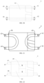
FIG. 9 is a schematic assembly diagram (a first contact state) of a driving component and a microswitch according to some embodiments of the present disclosure; -
FIG. 10 is a top view ofFIG. 9 ; -
FIG. 11 is a front view ofFIG. 9 ; -
FIG. 12 is a schematic assembly diagram (a second contact state) of a driving component and a microswitch according to some embodiments of the present disclosure; -
FIG. 13 is a top view ofFIG. 12 ; -
FIG. 14 is a front view ofFIG. 12 ; -
FIG. 15 is a schematic structural diagram (without a housing) of a contactor according to some other embodiments of the present disclosure; -
FIG. 16 is a top view ofFIG. 15 ; -
FIG. 17 is a front view of a driving component according to some embodiments of the present disclosure; -
FIG. 18 is a schematic structural diagram of a driving component according to some embodiments of the present disclosure; -
FIG. 19 is a top view of a driving component according to some embodiments of the present disclosure; -
FIG. 20 is a schematic structural diagram of a microswitch according to some embodiments of the present disclosure; -
FIG. 21 is a schematic structural diagram of a microswitch according to some other embodiments of the present disclosure; and -
FIG. 22 is a schematic structural diagram of a microswitch according to still some other embodiments of the present disclosure. -
- 100: contactor; and
- 1: first terminal; 2: second terminal; 3: conductive strip; 31: first conduction section; 32: second conduction section; 33: flexible connecting piece; 4: microswitch; 41: first magnetic pole; 42: second magnetic pole; 43: third magnetic pole; 44: fourth magnetic pole; 45: first magnet; 46: second magnet; 47: first magnetic plate; 48: second magnetic plate; 49: magnetic member; 5: driving component; 51: driving coil; 52: magnetic driving piece; 521: first magnetic conductive sheet; 522: second magnetic conductive sheet; 53: magnetic column; 54: magnetic conductive plate; 61: driving board; 62: clamping piece; 63: clamping port; 7: housing; 71: mounting piece; 711: mounting hole; 8: low-voltage signal end; and 9: sensor.
- The embodiments of present disclosure are described in detail below, and examples thereof are illustrated in the drawings, throughout which identical or similar elements or elements having identical or similar functions are represented with identical or similar reference numerals. The following embodiments described with reference to the drawings are exemplary, and are intended only to interpret the present disclosure, instead of limiting the present disclosure.
- A
contactor 100 according to the embodiments of the present disclosure is described below with reference toFIGs. 1 to 19 . Thecontactor 100 is provided with at least two terminal groups, that is, at least two high-voltage circuits are arranged on thecontactor 100. In addition, thecontactor 100 is provided with at least twomicroswitches 4 andconductive strips 3. The at least twomicroswitches 4 andconductive strips 3 share the same driving component, so that the at least twomicroswitches 4 are controlled by the same driving component to rotate simultaneously, and the at least twomicroswitches 4 drive the at least twoconductive strips 3 to rotate simultaneously, to implement synchronous on-off of the at least two high-voltage circuits. - This helps improve integration of the
contactor 100, improve space utilization inside thecontactor 100, and reduce the number of parts of thedriving component 5, thereby reducing the number of risk points, making thecontactor 100 more compact in shape, and facilitating miniaturization and lightweight design of thecontactor 100. - As shown in
FIGs. 4 to 8 , thecontactor 100 according to the embodiments of the present disclosure includes: a terminal group, aconductive strip 3, amicroswitch 4, and adriving component 5. - As shown in
FIG. 1 , the terminal group includes afirst terminal 1 and asecond terminal 2, at least two terminal groups are arranged, the two terminal groups are spaced apart on a side of thecontactor 100, and thefirst terminal 1 and thesecond terminal 2 are selectively connected. Therefore, at least two high-voltage circuits can be formed on thecontactor 100. - Further, the
conductive strip 3 includes afirst conduction section 31 and asecond conduction section 32 that are movably connected. A composite metal such as soft copper (silver) is added into a material of theconductive strip 3, so that theconductive strip 3 can be made of a new material with smaller volume and smaller mass, and theconductive strip 3 can have a larger current carrying capacity. This can also reduce the number of moving contacts, reduce high-voltage power consumption caused by the moving contacts, reduce arcing, reduce adhesion points, and reduce action wear generated during circuit control of thecontactor 100. In short, risk points and a power loss are reduced. - During operation of the
contactor 100, thesecond conduction section 32 impacts thesecond terminal 2, and operating noise occurs. To reduce the operating noise of thecontactor 100, theconductive strip 3 of the present disclosure may be constructed as a flexible member, which may be made of a flexible metal material (for example, a soft copper composite material or a soft silver composite material), to reduce impact noise and improve use experience of thecontactor 100. In addition, using the flexible metal material can increase a current, reduce contact resistance between thesecond terminal 2 and theconductive strip 3, and reduce a probability of adhesion between the two. - It should be noted that, that the
first conduction section 31 and thesecond conduction section 32 are movably connected means that the two may be connected by a conductive rotary connecting structure to implement relative rotation, or may be connected by a flexible structural member (that is, at least a portion of theconductive strip 3 is constructed as a flexible structure) and implement relative rotation through bending of the flexible structure, or theconductive strip 3 may be wholly constructed as a flexible member and implement relative rotation through bending. With the foregoing structure, bending wear of theconductive strip 3 is smaller during rotation of thesecond conduction section 32, which can prolong the service life of theconductive strip 3, to prolong the service life of thecontactor 100. - Specifically, the
first conduction section 31 is connected to thefirst terminal 1, and themicroswitch 4 is connected to thesecond conduction section 32. At least twomicroswitches 4, at least twoconductive strips 3, and at least two terminal groups are arranged and in a one-to-one correspondence. Thedriving component 5 is configured to drive the at least twomicroswitches 4 to rotate for driving to implement selective disconnection or connection between correspondingsecond conduction sections 32 andsecond terminals 2. - It can be understood that the
first conduction section 31 is connected to thefirst terminal 1, and themicroswitch 4 is connected to thesecond conduction section 32 to drive thesecond conduction section 32 to rotate. Specifically, during actual control of thecontactor 100, thedriving component 5 drives themicroswitch 4 so that themicroswitch 4 drives thesecond conduction section 32 to move toward/away from thesecond terminal 2, so as to implement selective connection or disconnection between thesecond conduction section 32 and thesecond terminal 2. - Therefore, the
first terminal 1 and thesecond terminal 2 may be electrically connected or disconnected selectively by theconductive strip 3, and thedriving component 5 is configured to drive themicroswitch 4 to drive theconductive strip 3 to move, so as to implement the connection or disconnection between thefirst terminal 1 and thesecond terminal 2. - Optionally, in the present disclosure, two
microswitches 4, twoconductive strips 3, and two terminal groups are arranged and in a one-to-one correspondence. Thefirst terminal 1 and thesecond terminal 2 are electrically connected through theconductive strip 3 by controlling selective disconnection or connection between thesecond conduction section 32 and thesecond terminal 2, so that thefirst terminal 1 forms a high-voltage circuit with thesecond terminal 2 through theconductive strip 3. - The
first conduction section 31 is connected to thefirst terminal 1, and themicroswitch 4 is connected to thesecond conduction section 32 to drive thesecond conduction section 32 to rotate. Specifically, during actual control of thecontactor 100, thedriving component 5 simultaneously drives the twomicroswitches 4 so that the twomicroswitches 4 drive two correspondingsecond conduction sections 32 to move toward/away from correspondingsecond terminals 2, so as to implement selective connection or disconnection between the twosecond conduction sections 32 and the correspondingsecond terminals 2. - Therefore, the two
microswitches 4 are simultaneously controlled by the onedriving component 5, which helps reduce the number of parts of thedriving component 5, reduce the number of risk points, make thecontactor 100 more compact in shape, and facilitate miniaturization and lightweight design of thecontactor 100. In addition, the at least twomicroswitches 4 are controlled by the same driving component to rotate simultaneously, thereby implementing synchronous on-off of multiple high-voltage circuits, and enhancing practicability of thecontactor 100. - The
contactor 100 according to the embodiments of the present disclosure is provided with at least twomicroswitches 4 andconductive strips 3, and the at least twomicroswitches 4 andconductive strips 3 share the same driving component, so that the at least twomicroswitches 4 are controlled by the same driving component to rotate simultaneously and drive the at least twoconductive strips 3 to rotate simultaneously, thereby implementing synchronous on-off of multiple high-voltage circuits, reducing the number of parts of thedriving component 5, reducing the number of risk points, making thecontactor 100 more compact in shape, and facilitating miniaturization and lightweight design of thecontactor 100. - In some embodiments, as shown in
FIG. 17 , thedriving component 5 includes a drivingcoil 51 and twomagnetic driving pieces 52, the twomagnetic driving pieces 52 may be respectively arranged at two ends of the drivingcoil 51, and the drivingcoil 51 may be connected to themagnetic driving pieces 52. - Further, as shown in
FIGs. 5 and 6 , twomicroswitches 4 are arranged and in a one-to-one correspondence with the twomagnetic driving pieces 52, that is, eachmagnetic driving piece 52 can drive a correspondingmicroswitch 4 to rotate. The drivingcoil 51 is configured to change a magnetic state of themagnetic driving pieces 52 to drive themicroswitches 4 to rotate. - For example, the driving
coil 51 may be supplied with a low-voltage current, and a magnetic state of themagnetic driving piece 52 connected to the drivingcoil 51 is changed by changing a flow direction of the current in the drivingcoil 51, so that themagnetic driving piece 52 can generate different magnetic fields, and under the action of the magnetic fields, themagnetic driving piece 52 generates a magnetic driving force for themicroswitch 4 to move toward or away from themagnetic driving piece 52. Therefore, with the magnetic driving force, thesecond conduction section 32 of theconductive strip 3 rotates toward/away from thesecond terminal 2. - It should be noted that, when the current flowing in the driving
coil 51 has an opposite flow direction, the twomagnetic driving pieces 52 have an opposite magnetic state. - Therefore, the magnetic state of the
magnetic driving pieces 52 is changed by changing the flow direction of the low-voltage current flowing through the drivingcoil 51, to drive the twomicroswitches 4 to rotate toward/away from correspondingsecond terminals 2, so as to control whetherfirst terminals 1 are electrically connected to thesecond terminals 2 throughconductive strips 3, thereby simultaneously controlling on-off statuses of two high-voltage circuits. This facilitates synchronous on-off of multiple high-voltage circuits, facilitates heat dissipation, and achieves high safety and reliability. - Further, as shown in
FIGs. 17 to 19 thedriving component 5 further includes amagnetic column 53 and magneticconductive plates 54 connected to two ends of themagnetic column 53. - The driving
coil 51 is wound around themagnetic column 53. That is, in thecontactor 100 of the present disclosure, the drivingcoil 51 can be fastened by winding the drivingcoil 51 around themagnetic column 53, to enhance structural stability of the drivingcoil 51, and themagnetic column 53 can enhance a magnetic field generated by the drivingcoil 51. Therefore, when thecontactor 100 is supplied with power, a current flows into the drivingcoil 51, so that the drivingcoil 51 generates a magnetic field, and themagnetic column 53 can enhance the magnetic field generated by the drivingcoil 51, thereby enhancing the magnetic driving force of thedriving component 5 to themicroswitch 4, making thesecond conduction section 32 of theconductive strip 3 rotate toward/away from thesecond terminal 2 more quickly, improving on-off efficiency of the high-voltage circuit of thecontactor 100, and enhancing sensitivity of thecontactor 100. - As shown in
FIG. 19 , the twomagnetic driving pieces 52 are respectively arranged on two sides of themagnetic column 53 and both are connected to the two magneticconductive plates 54. It can be understood that the two magneticconductive plates 54 are respectively arranged at the two ends of themagnetic column 53, and each magneticconductive plate 54 is connected to onemagnetic driving piece 52, so that magnetism generated by themagnetic column 53 is transferred to themagnetic driving piece 52 through the magneticconductive plate 54. - Each
magnetic driving piece 52 includes a first magneticconductive sheet 521 and a second magneticconductive sheet 522 that are spaced apart. As shown inFIG. 19 , first magneticconductive sheets 521 corresponding to the twomagnetic driving pieces 52 are symmetrically arranged on two sides of the magneticconductive plate 54, and second magneticconductive sheets 522 corresponding to the twomagnetic driving pieces 52 are also symmetrically arranged on the two sides of the magneticconductive plate 54. - Specifically, as shown in
FIG. 19 , the first magneticconductive sheet 521 is connected to a magneticconductive plate 54 at a first end of themagnetic column 53, and the second magneticconductive sheet 522 is connected to a magneticconductive plate 54 at a second end of themagnetic column 53, so that the magneticconductive plate 54 at the first end of themagnetic column 53 transfers magnetism generated by the drivingcoil 51 to the first magneticconductive sheet 521 to change a magnetic state of the first magneticconductive sheet 521, and the magneticconductive plate 54 at the second end of themagnetic column 53 transfers magnetism generated by the drivingcoil 51 to the second magneticconductive sheet 522 to change a magnetic state of the second magneticconductive sheet 522. - It should be noted that, magnetic states generated by the first magnetic
conductive sheet 521 and the second magneticconductive sheet 522 are opposite. - Further, a first end of the
microswitch 4 is provided with a firstmagnetic pole 41 and a secondmagnetic pole 42 that are spaced apart, and a second end of themicroswitch 4 is provided with a thirdmagnetic pole 43 and a fourthmagnetic pole 44 that are spaced apart. The first magneticconductive sheet 521 extends between the firstmagnetic pole 41 and the secondmagnetic pole 42 for engagement with one of the firstmagnetic pole 41 and the secondmagnetic pole 42, and the second magneticconductive sheet 522 extends between the thirdmagnetic pole 43 and the fourthmagnetic pole 44 for engagement with one of the thirdmagnetic pole 43 and the fourthmagnetic pole 44. - It can be understood that the first
magnetic pole 41 and the secondmagnetic pole 42 are both arranged at the first end of themicroswitch 4, and are spaced apart so that a movable space is defined between the firstmagnetic pole 41 and the secondmagnetic pole 42, the first magneticconductive sheet 521 extends into the movable space, and the first magneticconductive sheet 521 can rotate in the movable space; and the thirdmagnetic pole 43 and the fourthmagnetic pole 44 are both arranged at the second end of themicroswitch 4, and are spaced apart so that a movable space is defined between the thirdmagnetic pole 43 and the fourthmagnetic pole 44, the second magneticconductive sheet 522 extends into the movable space, and the second magneticconductive sheet 522 can rotate in the movable space. - It should be noted that, the first magnetic
conductive sheet 521 extends between the firstmagnetic pole 41 and the secondmagnetic pole 42, and the second magneticconductive sheet 522 extends between the thirdmagnetic pole 43 and the fourthmagnetic pole 44, so that the firstmagnetic pole 41 and the secondmagnetic pole 42 can be limited by the first magneticconductive sheet 521, and the thirdmagnetic pole 43 and the fourthmagnetic pole 44 can be limited by the second magneticconductive sheet 522, thereby preventing themicroswitch 4 from disengaging, and enhancing structural stability of themicroswitch 4. - Then, polarities of the first magnetic
conductive sheet 521 and the second magneticconductive sheet 522 are changed by supplying currents of different flow directions in the drivingcoil 51, so that under the action of the magnetic driving force, the first magneticconductive sheet 521 moves toward one of the firstmagnetic pole 41 and the secondmagnetic pole 42 whose polarity is opposite to a polarity of the first magneticconductive sheet 521, and the second magneticconductive sheet 522 moves toward one of the thirdmagnetic pole 43 and the fourthmagnetic pole 44 whose polarity is opposite to a polarity of the second magneticconductive sheet 521. - It should be noted that, under the action of the magnetic driving force, the first magnetic
conductive sheet 521 generates a thrust force to one of the firstmagnetic pole 41 and the secondmagnetic pole 42 whose polarity is the same as the polarity of the first magneticconductive sheet 521, and the second magneticconductive sheet 522 also generates a thrust force to one of the thirdmagnetic pole 43 and the fourthmagnetic pole 44 whose polarity is the same as the polarity of the second magneticconductive sheet 522, which increases a rotation speed of themicroswitch 4, thereby increasing an on-off speed of the high-voltage circuit of thecontactor 100, and enhancing practicability of thecontactor 100. - Therefore, the polarities of the first magnetic
conductive sheet 521 and the second magneticconductive sheet 522 can be changed by supplying a current in the drivingcoil 51, so that the first magneticconductive sheet 521 can be engaged with either of the firstmagnetic pole 41 and the secondmagnetic pole 42, and the second magneticconductive sheet 522 can be engaged with either of the thirdmagnetic pole 43 and the fourthmagnetic pole 44, and then themicroswitch 4 drives theconductive strip 3 to move toward/away from thesecond terminal 2, thereby implementing synchronous on-off of the two high-voltage circuits of thecontactor 100, and enhancing sensitivity of thecontactor 100. - For example, as shown in
FIGs. 9 to 11 , thecontactor 100 is in a first operating state, that is, the first magneticconductive sheet 521 is engaged with the secondmagnetic pole 42, and the second magneticconductive sheet 522 is engaged with the thirdmagnetic pole 43. In this case, thesecond conduction section 32 can be electrically connected to thesecond terminal 2, and the high-voltage circuit of thecontactor 100 is turned on. - Alternatively, as shown in
FIGs. 12 to 14 , thecontactor 100 is in a second operating state, that is, the first magneticconductive sheet 521 is engaged with the firstmagnetic pole 41, and the second magneticconductive sheet 522 is engaged with the fourthmagnetic pole 44. In this case, thesecond conduction section 32 can be separated from thesecond terminal 2, and the high-voltage circuit of thecontactor 100 is turned off. - In other words, when the
contactor 100 is in the first operating state, the high-voltage circuit of thecontactor 100 is turned on; and when thecontactor 100 is in the second operating state, the high-voltage circuit of thecontactor 100 is turned off. Certainly, when thecontactor 100 is in the first operating state, the high-voltage circuit of thecontactor 100 may alternatively be turned off; and when thecontactor 100 is in the second operating state, the high-voltage circuit of thecontactor 100 may alternatively be turned on. - Therefore, the first magnetic
conductive sheet 521 can be engaged with either of the firstmagnetic pole 41 and the secondmagnetic pole 42, and the second magneticconductive sheet 522 can be engaged with either of the thirdmagnetic pole 43 and the fourthmagnetic pole 44, so that themicroswitch 4 drives theconductive strip 3 to move toward/away from thesecond terminal 2, thereby implementing synchronous on-off of the two high-voltage circuits of thecontactor 100, and enhancing sensitivity of thecontactor 100. - The polarity of the first magnetic
conductive sheet 521 is opposite to the polarity of the second magneticconductive sheet 522. It should be noted that, the polarities of the first magneticconductive sheet 521 and the second magneticconductive sheet 522 are determined by a flow direction of a current flowing in the drivingcoil 51. - A polarity of the first
magnetic pole 41 is opposite to a polarity of the secondmagnetic pole 42, and a polarity of the thirdmagnetic pole 43 is opposite to a polarity of the fourthmagnetic pole 44, so that the firstmagnetic pole 41 and the secondmagnetic pole 42 are not engaged with each other, and the thirdmagnetic pole 43 and the fourthmagnetic pole 44 are not engaged with each other either. - Therefore, during actual operation of the
contactor 100, the first magneticconductive sheet 521 generates a suction force to one of the firstmagnetic pole 41 and the secondmagnetic pole 42 whose polarity is opposite to the polarity of the first magneticconductive sheet 521 and a thrust force to the other, and the second magneticconductive sheet 522 generates a suction force to one of the thirdmagnetic pole 43 and the fourthmagnetic pole 44 whose polarity is opposite to the polarity of the second magneticconductive sheet 522 and a thrust force to the other, thereby improving rotation efficiency of themicroswitch 4, implementing quick on-off of the high-voltage circuit of thecontactor 100, and enhancing sensitivity of thecontactor 100. - In some embodiments, the polarity of the first magnetic
conductive sheet 521 is opposite to the polarity of the second magneticconductive sheet 522. - Specifically, both the first
magnetic pole 41 and the secondmagnetic pole 42 are constructed with opposite polarities on an inner side and an outer side, and the polarity of the inner side of the firstmagnetic pole 41 is opposite to the polarity of the inner side of the secondmagnetic pole 42. - It can be understood that polarities of the inner sides and the outer sides of the first
magnetic pole 41 and the secondmagnetic pole 42 are opposite, a polarity of a side of the firstmagnetic pole 41 close to the first magneticconductive sheet 521 is opposite to a polarity of a side of the secondmagnetic pole 42 close to the first magneticconductive sheet 521, and a polarity of a side of the firstmagnetic pole 41 facing away from the first magneticconductive sheet 521 is opposite to a polarity of a side of the secondmagnetic pole 42 facing away from the first magneticconductive sheet 521. This helps improve magnetic sensitivity of the firstmagnetic pole 41 and the secondmagnetic pole 42, thereby improving rotation efficiency of themicroswitch 4, implementing quick on-off of the high-voltage circuit of thecontactor 100, and enhancing sensitivity of thecontactor 100. - Both the third
magnetic pole 43 and the fourthmagnetic pole 44 are constructed with opposite polarities on an inner side and an outer side, and the polarity of the inner side of the thirdmagnetic pole 43 is opposite to the polarity of the inner side of the fourthmagnetic pole 44. - It can be understood that polarities of the inner sides and the outer sides of the third
magnetic pole 43 and the fourthmagnetic pole 44 are opposite, a polarity of a side of the thirdmagnetic pole 43 close to the second magneticconductive sheet 522 is opposite to a polarity of a side of the fourthmagnetic pole 44 close to the second magneticconductive sheet 522, and a polarity of a side of the thirdmagnetic pole 43 facing away from the second magneticconductive sheet 522 is opposite to a polarity of a side of the fourthmagnetic pole 44 facing away from the second magneticconductive sheet 522. This helps improve magnetic sensitivity of the thirdmagnetic pole 43 and the fourthmagnetic pole 44, thereby improving rotation efficiency of themicroswitch 4, implementing quick on-off of the high-voltage circuit of thecontactor 100, and enhancing sensitivity of thecontactor 100. - It should be noted that, the first
magnetic pole 41, the secondmagnetic pole 42, the thirdmagnetic pole 43, and the fourthmagnetic pole 44 are all permanent magnets. - Further, as shown in
FIG. 20 , the firstmagnetic pole 41 and the thirdmagnetic pole 43 are integrally formed, and the secondmagnetic pole 42 and the fourthmagnetic pole 44 are integrally formed. - For example, the first
magnetic pole 41 and the thirdmagnetic pole 43 are integrally constructed, and the secondmagnetic pole 42 and the fourthmagnetic pole 44 are integrally constructed, which reduces processing difficulty and production costs. In addition, as shown inFIG. 20 , the inner sides of the firstmagnetic pole 41 and the thirdmagnetic pole 43 are both constructed as N poles, the outer sides of the firstmagnetic pole 41 and the thirdmagnetic pole 43 are both constructed as S poles, the inner sides of the secondmagnetic pole 42 and the fourthmagnetic pole 44 are both constructed as S poles, and the outer sides of the secondmagnetic pole 42 and the fourthmagnetic pole 44 are both constructed as N poles. - This helps improve magnetic sensitivity of the
microswitch 4, thereby improving rotation efficiency of themicroswitch 4, implementing quick on-off of the high-voltage circuit of thecontactor 100, and enhancing sensitivity of thecontactor 100. - In some other embodiments, as shown in
FIG. 21 , the first end (a right end inFIG. 21 ) of themicroswitch 4 is provided with afirst magnet 45 constructed in a U shape, two ends of thefirst magnet 45 are respectively constructed as the firstmagnetic pole 41 and the secondmagnetic pole 42, a second end (a left end inFIG. 21 ) of themicroswitch 4 is provided with asecond magnet 46 constructed in a U shape, and two ends of thesecond magnet 46 are respectively constructed as the thirdmagnetic pole 43 and the fourthmagnetic pole 44. - It can be understood that in some other embodiments, the first
magnetic pole 41 and the secondmagnetic pole 42 are integrally formed, and the thirdmagnetic pole 43 and the fourthmagnetic pole 44 are integrally formed, which reduces processing difficulty and production costs. - In addition, as shown in
FIG. 21 , the polarity of the firstmagnetic pole 41 is opposite to the polarity of the secondmagnetic pole 42, and the polarity of the thirdmagnetic pole 43 is opposite to the polarity of the fourthmagnetic pole 44. For example, both the firstmagnetic pole 41 and the thirdmagnetic pole 43 may be constructed as N poles, and both the secondmagnetic pole 42 and the fourthmagnetic pole 44 may be constructed as S poles. This helps improve magnetic sensitivity of themicroswitch 4, thereby improving rotation efficiency of themicroswitch 4, implementing quick on-off of the high-voltage circuit of thecontactor 100, and enhancing sensitivity of thecontactor 100. - In still some other embodiments, as shown in
FIG. 22 , a firstmagnetic plate 47 and a secondmagnetic plate 48 are respectively arranged on two sides of themicroswitch 4, amagnetic member 49 is arranged between the firstmagnetic plate 47 and the secondmagnetic plate 48, polarities of two ends of themagnetic member 49 are opposite, a polarity of the firstmagnetic plate 47 is the same as a polarity of a first end of themagnetic member 49, and a polarity of the secondmagnetic plate 48 is the same as a polarity of a second end of themagnetic member 49. Two ends of the firstmagnetic plate 47 are respectively constructed as the firstmagnetic pole 41 and the thirdmagnetic pole 43, and two ends of the secondmagnetic plate 48 are respectively constructed as the secondmagnetic pole 42 and the fourthmagnetic pole 44. - It can be understood that, in still some other embodiments, magnetism of the first
magnetic plate 47 is determined by magnetism of the first end of themagnetic member 49, and magnetism of the secondmagnetic plate 48 is determined by magnetism of the second end of themagnetic member 49, that is, the firstmagnetic pole 41 and the thirdmagnetic pole 43 have the same magnetism as the first end of themagnetic member 49, and the secondmagnetic pole 42 and the fourthmagnetic pole 44 have the same magnetism as the second end of themagnetic member 49. - For example, as shown in
FIG. 22 , the first end (an upper end inFIG. 22 ) of themagnetic member 49 is constructed as an N pole, and the second end (a lower end inFIG. 22 ) of themagnetic member 49 is constructed as an S pole, so that both the firstmagnetic pole 41 and the thirdmagnetic pole 43 at the two ends of the firstmagnetic plate 47 are N poles, and both the secondmagnetic pole 42 and the fourthmagnetic pole 44 at the two ends of the secondmagnetic plate 48 are S poles. This helps reduce production difficulty of themicroswitch 4, and improve magnetic sensitivity of themicroswitch 4, thereby improving rotation efficiency of themicroswitch 4, implementing quick on-off of the high-voltage circuit of thecontactor 100, and enhancing sensitivity of thecontactor 100. - In some other embodiments, the
microswitch 4 includes a drivingboard 61 and aclamping piece 62 connected to the drivingboard 61. The drivingboard 61 and theclamping piece 62 may be integrally formed, which reduces processing steps of themicroswitch 4 and improves production efficiency. - In still some other embodiments, the driving
board 61 is constructed as a magnetic body, and magnetism of an upper portion of the drivingboard 61 is opposite to magnetism of a lower portion of the drivingboard 61, so that the polarities of the first magneticconductive sheet 521 and the second magneticconductive sheet 522 can be changed by supplying a current in the drivingcoil 51, the first magneticconductive sheet 521 can be engaged with either of the firstmagnetic pole 41 and the secondmagnetic pole 42, and the second magneticconductive sheet 522 can be engaged with either of the thirdmagnetic pole 43 and the fourthmagnetic pole 44, and then themicroswitch 4 drives theconductive strip 3 to move toward/away from thesecond terminal 2, thereby implementing synchronous on-off of the two high-voltage circuits of thecontactor 100, and enhancing sensitivity of thecontactor 100. - Further, as shown in
FIGs. 10 and13 , the drivingboard 61 is arranged between thefirst conduction section 31 and thesecond conduction section 32, and the firstmagnetic pole 41, the secondmagnetic pole 42, the thirdmagnetic pole 43, and the fourthmagnetic pole 44 are respectively arranged at four corners of the drivingboard 61, and are respectively arranged on opposite sides of the drivingboard 61, so that the first magneticconductive sheet 521 can extend between the firstmagnetic pole 41 and the secondmagnetic pole 42, the second magneticconductive sheet 522 can extend between the thirdmagnetic pole 43 and the fourthmagnetic pole 44, the drivingboard 61 can drive the four magnetic poles to move synchronously, one of the firstmagnetic pole 41 and the secondmagnetic pole 42 is engaged with the first magneticconductive sheet 521, and one of the thirdmagnetic pole 43 and the fourthmagnetic pole 44 is engaged with the second magneticconductive sheet 522, thereby implementing on-off control over the high-voltage circuit of thecontactor 100. - As shown in
FIGs. 11 ,12, and 14 , the clampingpiece 62 is provided with a clampingport 63, the clampingport 63 is recessed toward a direction of the drivingboard 61, and thesecond conduction section 32 is clamped in the clampingport 63, thereby improving structural stability of thesecond conduction section 32, and enhancing motion stability of theconductive strip 3. - Therefore, a connecting structure does not need to be separately arranged between the driving
board 61 and theconductive strip 3, which simplifies an internal structure of thecontactor 100 and reduces space for mounting theconductive strip 3, thereby implementing miniaturization design of thecontactor 100. In addition, with the clampingport 63 arranged, the drivingboard 61 easily drives thesecond conduction section 32 to move toward/away from thesecond terminal 2, thereby implementing on-off control over the high-voltage circuit of thecontactor 100. - In some embodiments, the
first terminal 1 and thesecond terminal 2 are arranged opposite to theconductive strip 3 in a first direction, and at least one of theconductive strip 3, thefirst terminal 1, and thesecond terminal 2 is arranged opposite to thedriving component 5 in a second direction. The first direction is orthogonal to the second direction. - Referring to
FIGs. 5 and 6 , theconductive strip 3 is arranged opposite to thefirst terminal 1 and thesecond terminal 2 in the first direction, and thedriving component 5 is arranged opposite to at least one of theconductive strip 3, thefirst terminal 1, and thesecond terminal 2 in the second direction. For example, the first direction corresponds to a length direction or a width direction on a horizontal plane, and the second direction corresponds to a height direction. In this case, thefirst terminal 1 and thesecond terminal 2 are arranged at the same height as theconductive strip 3, and thedriving component 5 is arranged above or below theconductive strip 3. Optionally, thedriving component 5 is arranged below theconductive strip 3, to reduce a dimension of thecontactor 100 in the height direction. - In addition, with the foregoing arrangement, the
contactor 100 can be arranged in layers, and high-low voltage isolation can be implemented (an upper layer is a high-voltage conduction part, and a lower layer is a low-voltage control part), so that an arc extinguishing manner is not limited to a combination of an inert gas and magnetic blowout for arc extinguishing, and may be implemented through integral infiltration by an insulating liquid. Alternatively, no arc extinguishing structure is arranged. Based on diversity of arc extinguishing manners, thedriving component 5 does not need to be insulated or isolated from a chamber, which can resolve a problem of a low-voltage failure. In addition, an inert gas does not need to be injected, and a ceramic and metal brazing process does not need to be performed to process thecontactor 100, which can simplify a processing process of thecontactor 100, reduce a material process, improve production efficiency, and reduce processing costs of thecontactor 100. - In still some other embodiments, as shown in
FIGs. 15 and 16 , theconductive strip 3 further includes a flexible connectingpiece 33. - The flexible connecting
piece 33 is connected between thefirst conduction section 31 and thesecond conduction section 32. Thesecond conduction section 32 is adapted to move toward or away from thesecond terminal 2 through deformation of the flexible connectingpiece 33. - It can be understood that the flexible connecting
piece 33 in the present disclosure may be made of a flexible metal material (for example, a soft copper composite material or a soft silver composite material), to reduce impact noise and improve use experience of thecontactor 100. In addition, using the flexible metal material can increase a current, reduce contact resistance between thesecond terminal 2 and theconductive strip 3, and reduce a probability of adhesion between the two. - In some embodiments, the
contactor 100 further include asensor 9 and a controller. - The
sensor 9 is arranged close to thefirst terminal 1, thesecond terminal 2, or theconductive strip 3 to detect a circuit signal of thefirst terminal 1, thesecond terminal 2, or theconductive strip 3 in real time. The controller is electrically connected to thesensor 9 to control, according to the circuit signal, thedriving component 5 to switch off or switch on the electrical connection between thesecond conduction section 32 and thesecond terminal 2. - Optionally, the
sensor 9 is arranged close to theconductive strip 3 to detect a circuit signal of theconductive strip 3 in real time, and thesensor 9 can transmit the detected circuit signal of theconductive strip 3 to the controller in real time, so that the controller can control, according to the circuit signal detected by thesensor 9, theconductive strip 3 to be connected to or disconnected from thesecond terminal 2. Especially in extreme operating conditions, it can be ensured that the high-voltage circuit can be supplied with high-voltage power, to improve safety of the high-voltage circuit. - The controller may be an existing host computer of a vehicle, and the
sensor 9 and the host computer use a controller area network (CAN) for communication and control, so that the existing host computer controls thesensor 9, which simplifies a control structure for thesensor 9 and reduces production costs. - Specifically, the controller is configured to obtain a temperature, a voltage, or a current of the
first terminal 1, thesecond terminal 2, or theconductive strip 3 according to the circuit signal. The controller is configured to: for thefirst terminal 1, thesecond terminal 2, or theconductive strip 3, when the temperature is greater than a first temperature threshold, and/or the voltage is greater than a first voltage threshold, and/or the current is greater than a first current threshold, control thedriving component 5 to rotate theconductive strip 3, so that thesecond conduction section 32 is separated from thesecond terminal 2, to switch off the electrical connection between thefirst terminal 1 and thesecond terminal 2. - That is, when a signal of the high-voltage circuit detected by the
sensor 9 is greater than the first temperature threshold and/or the first voltage threshold and/or the first current threshold, thesensor 9 transmits the circuit signal to the controller, and the controller controls thedriving component 5 to rotate theconductive strip 3, so that thesecond conduction section 32 is separated from thesecond terminal 2, to switch off the electrical connection between thefirst terminal 1 and thesecond terminal 2, thereby disconnecting thecontactor 100, and improving safety of thecontactor 100. - Further, the controller is configured to: for the
first terminal 1, thesecond terminal 2, or theconductive strip 3, when the temperature is less than a second temperature threshold, and/or the voltage is less than a second voltage threshold, and/or the current is less than a second current threshold, switch on the electrical connection between thesecond conduction section 32 and thesecond terminal 2, that is, control thedriving component 5 to rotate theconductive strip 3, so that thesecond conduction section 32 is connected to thesecond terminal 2, thereby closing the electrical connection between thefirst terminal 1 and thesecond terminal 2. - That is, when a signal of the high-voltage circuit detected by the
sensor 9 is less than the second temperature threshold and/or the second voltage threshold and/or the second current threshold, thesensor 9 transmits the circuit signal to the controller, and the controller controls thedriving component 5 to rotate theconductive strip 3, so that thesecond conduction section 32 is connected to thesecond terminal 2, thereby closing the electrical connection between thefirst terminal 1 and thesecond terminal 2. - The second temperature threshold is less than or equal to the first temperature threshold, the second voltage threshold is less than or equal to the first voltage threshold, and the second current threshold is less than or equal to the first current threshold.
- It can be understood that the circuit signal includes a temperature change, a voltage change, a current change, and the like, and is not limited herein. Therefore, the controller can control the
driving component 5 according to one or more of temperature, voltage, and current signals detected by thesensor 9, to control theconductive strip 3 to be connected to or disconnected from thesecond terminal 2. In addition, thesensor 9 and the controller can be arranged in place of a fuse, so that the fuse does not need to be arranged in the high-voltage circuit of thecontactor 100, which can reduce a high-voltage loss, and can ensure that the high-voltage circuit can be supplied with high-voltage power in extreme operating conditions, thereby improving safety of the high-voltage circuit. - In some examples, the
sensor 9 is welded on theconductive strip 3, and electrically connected to the host computer. As theconductive strip 3 connects thefirst terminal 1 and thesecond terminal 2, both a current carrying capacity and heat productivity of the high-voltage circuit change, and a temperature change occurs correspondingly. Thesensor 9 may obtain change information (a temperature change, a current carrying capacity change, and the like) during operation of the high-voltage circuit. Thesensor 9 is configured to detect a temperature change of theconductive strip 3, and transmit the temperature change to the controller in a form of a circuit signal. The controller determines, according to the circuit signal, whether a cut-off threshold of the high-voltage circuit is reached, and when the high-voltage circuit needs to be turned off, controls thedriving component 5 to release the electrical connection between thesecond conduction section 32 and thesecond terminal 2. No fuse needs to be arranged, which reduces a high-voltage loss and costs. In addition, after thecontactor 100 is controlled disconnected, if a power consuming device using thecontactor 100 of the present disclosure needs to continue operation, it can still be ensured that the power consuming device can be supplied with a high voltage, thereby improving safety. - It should be noted that, the high-voltage circuit is completely turned off after the fuse is blown, while according to the present disclosure, with the controller and the
sensor 9 arranged, even if the high-voltage circuit needs to be turned off based on information obtained by thesensor 9, high-voltage power can still be supplied in extreme conditions to improve safety. For example, thecontactor 100 of the present disclosure is applied to an electric vehicle. When circuit information indicates that thecontactor 100 needs to be disconnected but the vehicle is in a dangerous situation and an operating condition needs to be maintained, a high-voltage power supply state may be maintained, and the electrical connection between theconductive strip 3 and thesecond terminal 2 can be disconnected after the vehicle drives to a safe position or the dangerous situation passes. - Therefore, the
contactor 100 can be prevented from overheating due to an excessively high temperature of theconductive strip 3, which helps enhance safety of thecontactor 100. In addition, when the vehicle is in a dangerous situation and an operating condition needs to be maintained, the high-voltage power supply state may be maintained, thereby enhancing practicability of thecontactor 100. - Certainly, the
sensor 9 may alternatively be arranged in other structural forms at other positions of the high-voltage circuit to detect a circuit signal of the high-voltage circuit. This is not limited herein. - In some embodiments, as shown in
FIGs. 1 to 4 , thecontactor 100 further includes ahousing 7. - The
housing 7 defines an accommodating space, and theconductive strip 3, thefirst terminal 1, thesecond terminal 2, and thedriving component 5 are arranged in the accommodating space, so that theconductive strip 3 and thedriving component 5 are not directly visible outside thecontactor 100. In addition, with thehousing 7 arranged, thedriving component 5 can be separated from outside, which improves operating stability, reduces interference of an external environment to thedriving component 5 and themicroswitch 4, and improves control and response efficiency of the low-voltage control part. At least a portion of thefirst terminal 1 and thesecond terminal 2 is extended out of thehousing 7 to form connecting terminals for electrically connecting thecontactor 100 to another structure. - A mounting
piece 71 is further arranged outside the housing, and a mountinghole 711 is formed on the mountingpiece 71, so that thecontactor 100 can be detachably connected to another structure through the mountingpiece 71, thereby facilitating attachment/detachment of thecontactor 100, and enhancing practicability of thecontactor 100. - Further, a low-
voltage signal end 8 is further arranged outside thehousing 7, and is connected to the drivingcoil 51. - Optionally, in some embodiments, the
housing 7 is provided with a harness outlet, and the low-voltage signal end 8 is led out of the housing through the harness outlet. In some other embodiments, the low-voltage signal end 8 is fastened onto thehousing 7 in a plug-in form, and thehousing 7 is correspondingly provided with a plug-in interface, and a metal wire is led through the plug-in interface into thehousing 7 for electrical connection to the drivingcoil 51, so that appearance of thecontactor 100 of the present disclosure is consistent with appearance of a conventional contactor, which facilitates structural design and material switching, and can reduce a development cycle and development costs. - The present disclosure also provides a charging and distribution system.
- The charging and distribution system according to the embodiments of the present disclosure is provided with the
contactor 100 in any one of the foregoing embodiments, thecontactor 100 is provided with at least twomicroswitches 4 andconductive strips 3, and the at least twomicroswitches 4 andconductive strips 3 share the same driving component, so that the at least twomicroswitches 4 are controlled by the same driving component to rotate simultaneously and drive the at least twoconductive strips 3 to rotate simultaneously, thereby implementing synchronous on-off of multiple high-voltage circuits, reducing the number of parts of thedriving component 5, reducing the number of risk points, making thecontactor 100 more compact in shape, and facilitating miniaturization and lightweight design of thecontactor 100. - The present disclosure also provides a vehicle.
- The vehicle according to the embodiments of the present disclosure is provided with the charging and distribution system in any one of the foregoing embodiments, whose
contactor 100 is provided with at least twomicroswitches 4 andconductive strips 3, and the at least twomicroswitches 4 andconductive strips 3 share the same driving component, so that the at least twomicroswitches 4 are controlled by the same driving component to rotate simultaneously and drive the at least twoconductive strips 3 to rotate simultaneously, thereby implementing synchronous on-off of multiple high-voltage circuits, reducing the number of parts of thedriving component 5, reducing the number of risk points, making thecontactor 100 more compact in shape, and facilitating miniaturization and lightweight design of thecontactor 100. In addition, using thecontactor 100 can improve operating stability and use safety of the charging and distribution system of the vehicle, and prolong the service life. - The present disclosure also provides a charging pile.
- The charging pile according to some embodiments of the present disclosure is provided with the
contactor 100 in any one of the foregoing embodiments, thecontactor 100 is provided with at least twomicroswitches 4 andconductive strips 3, and the at least twomicroswitches 4 andconductive strips 3 share the same driving component, so that the at least twomicroswitches 4 are controlled by the same driving component to rotate simultaneously and drive the at least twoconductive strips 3 to rotate simultaneously, thereby implementing synchronous on-off of multiple high-voltage circuits, reducing the number of parts of thedriving component 5, reducing the number of risk points, making thecontactor 100 more compact in shape, and facilitating miniaturization and lightweight design of thecontactor 100. In addition, using thecontactor 100 can improve use safety of the charging pile. - In the description of the present disclosure, it should be understood that orientation or position relationships indicated by the terms such as "center", "longitudinal", "transverse", "length", "width", "thickness", "above", "below", "front", "back", "left", "right", "vertical", "horizontal", "top", "bottom", "inside", "outside", "clockwise", "anticlockwise", "axial", "radial", and "circumferential" are based on orientation or position relationships shown in the accompanying drawings, and are used only for ease and brevity of illustration and description, rather than indicating or implying that the mentioned apparatus or element needs to have a particular orientation or needs to be constructed and operated in a particular orientation. Therefore, such terms should not be construed as limitations to the present disclosure.
- In the description of the present disclosure, a "first feature" or a "second feature" may include one or more such features.
- In the description of the present disclosure, "multiple" means two or more.
- In the description of the present disclosure, the first feature being "on" or "under" the second feature may mean that the first feature and the second feature are in direct contact, or may mean that the first feature and the second feature are not in direct contact but in contact through another feature therebetween.
- In the description of the present disclosure, the first feature being "on", "above", or "over" the second feature means that the first feature is right above or not right above the second feature, or merely indicates that a level of the first feature is higher than a level of the second feature.
- In the description of this specification, the description of the reference terms such as "an embodiment", "some embodiments", "exemplary embodiments", "example", "specific example", or "some examples" means that features, structures, materials, or characteristics described with reference to the embodiment or example is included in at least one embodiment or example of the present disclosure. In this specification, exemplary descriptions of the foregoing terms do not necessarily refer to the same embodiment or example. In addition, the described specific features, structures, materials, or characteristics may be combined in a proper manner in any one or more embodiments or examples.
- Although the embodiments of the present disclosure have been shown and described, a person of ordinary skill in the art may understand that various changes, modifications, replacements, and variations may be made to the embodiments without departing from the principle and spirit of the present disclosure, and the scope of the present disclosure is defined by the appended claims and their equivalents.
Claims (20)
- A contactor (100), comprising:a terminal group comprising a first terminal (1) and a second terminal (2);a conductive strip (3) comprising a first conduction section (31) and a second conduction section (32) being movably connected, the first conduction section (31) being connected to the first terminal (1);a microswitch (4) connected to the second conduction section (32), at least two microswitches (4), at least two conductive strips (3), and at least two terminal groups being arranged and in a one-to-one correspondence; anda driving component (5) configured to drive the at least two microswitches (4) to rotate for driving to implement selective disconnection or connection between corresponding second conduction sections (32) and second terminals (2).
- The contactor (100) according to claim 1, wherein the driving component (5) comprises a driving coil (51) and two magnetic driving pieces (52), and two microswitches (4) are arranged and in a one-to-one correspondence with the two magnetic driving pieces (52), wherein
the driving coil (51) is configured to change a magnetic state of the magnetic driving pieces (52) to drive the microswitches (4) to rotate. - The contactor (100) according to claim 2, wherein the driving component (5) further comprises a magnetic column (53) and magnetic conductive plates (54) connected to two ends of the magnetic column (53), the driving coil (51) is wound around the magnetic column (53), and the two magnetic driving pieces (52) are respectively arranged on two sides of the magnetic column (53) and both are connected to the two magnetic conductive plates (54).
- The contactor (100) according to claim 3, wherein each magnetic driving piece (52) comprises a first magnetic conductive sheet (521) and a second magnetic conductive sheet (522) that are spaced apart, the first magnetic conductive sheet (521) is connected to a magnetic conductive plate (54) at a first end of the magnetic column (53), and the second magnetic conductive sheet (522) is connected to a magnetic conductive plate (54) at a second end of the magnetic column (53); and a first end of the microswitch (4) is provided with a first magnetic pole (41) and a second magnetic pole (42) that are spaced apart, and a second end of the microswitch (4) is provided with a third magnetic pole (43) and a fourth magnetic pole (44) that are spaced apart, wherein
the first magnetic conductive sheet (521) extends between the first magnetic pole (41) and the second magnetic pole (42) for engagement with one of the first magnetic pole (41) and the second magnetic pole (42), and the second magnetic conductive sheet (522) extends between the third magnetic pole (43) and the fourth magnetic pole (44) for engagement with one of the third magnetic pole (43) and the fourth magnetic pole (44). - The contactor (100) according to claim 4, wherein a polarity of the first magnetic conductive sheet (521) is opposite to a polarity of the second magnetic conductive sheet (522), a polarity of the first magnetic pole (41) is opposite to a polarity of the second magnetic pole (42), and a polarity of the third magnetic pole (43) is opposite to a polarity of the fourth magnetic pole (44).
- The contactor (100) according to claim 4, wherein a polarity of the first magnetic conductive sheet (521) is opposite to a polarity of the second magnetic conductive sheet (522);both the first magnetic pole (41) and the second magnetic pole (42) are constructed with opposite polarities on an inner side and an outer side, and the polarity of the inner side of the first magnetic pole (41) is opposite to the polarity of the inner side of the second magnetic pole (42); andboth the third magnetic pole (43) and the fourth magnetic pole (44) are constructed with opposite polarities on an inner side and an outer side, and the polarity of the inner side of the third magnetic pole (43) is opposite to the polarity of the inner side of the fourth magnetic pole (44).
- The contactor (100) according to claim 6, wherein the first magnetic pole (41) and the third magnetic pole (43) are integrally formed, and the second magnetic pole (42) and the fourth magnetic pole (44) are integrally formed.
- The contactor (100) according to any one of claims 4 to 7, wherein the first end of the microswitch (4) is provided with a first magnet (45) constructed in a U shape, two ends of the first magnet (45) are respectively constructed as the first magnetic pole (41) and the second magnetic pole (42), and the second end of the microswitch (4) is provided with a second magnet (46) constructed in a U shape, two ends of the second magnet (46) are respectively constructed as the third magnetic pole (43) and the fourth magnetic pole (44).
- The contactor (100) according to any one of claims 4 to 8, wherein a first magnetic plate (47) and a second magnetic plate (48) are respectively arranged on two sides of the microswitch (4), a magnetic member (49) is arranged between the first magnetic plate (47) and the second magnetic plate (48), polarities of two ends of the magnetic member (49) are opposite, a polarity of the first magnetic plate (47) is the same as a polarity of a first end of the magnetic member (49), and a polarity of the second magnetic plate (48) is the same as a polarity of a second end of the magnetic member (49), wherein
two ends of the first magnetic plate (47) are respectively constructed as the first magnetic pole (41) and the third magnetic pole (43), and two ends of the second magnetic plate (48) are respectively constructed as the second magnetic pole (42) and the fourth magnetic pole (44). - The contactor (100) according to any one of claims 4 to 9, wherein the microswitch (4) comprises a driving board (61) and a clamping piece (62) connected to the driving board (61), the first magnetic pole (41), the second magnetic pole (42), the third magnetic pole (43), and the fourth magnetic pole (44) are respectively arranged at four corners of the driving board (61), the clamping piece (62) is provided with a clamping port (63), and the second conduction section (32) is clamped in the clamping port (63).
- The contactor (100) according to any one of claims 1 to 10, wherein the first terminal (1) and the second terminal (2) are arranged opposite to the conductive strip (3) in a first direction, and at least one of the conductive strip (3), the first terminal (1), and the second terminal (2) is arranged opposite to the driving component (5) in a second direction, the first direction being orthogonal to the second direction.
- The contactor (100) according to any one of claims 1 to 11, wherein the conductive strip (3) further comprises a flexible connecting piece (33) connected between the first conduction section (31) and the second conduction section (32), and the second conduction section (32) is adapted to move toward or away from the second terminal (2) through deformation of the flexible connecting piece (33).
- The contactor (100) according to any one of claims 1 to 12, further comprising: a sensor (9) arranged close to the first terminal (1), the second terminal (2), or the conductive strip (3) to detect a circuit signal of the first terminal (1), the second terminal (2), or the conductive strip (3) in real time; and
a controller electrically connected to the sensor (9) to control, according to the circuit signal, the driving component (5) to switch off or switch on the electrical connection between the second conduction section (32) and the second terminal (2). - The contactor (100) according to claim 13, wherein the controller is configured to obtain a temperature, a voltage, or a current of the first terminal (1), the second terminal (2), or the conductive strip (3) according to the circuit signal; and
the controller is configured to: for the first terminal (1), the second terminal (2), or the conductive strip (3), when the temperature is greater than a first temperature threshold, and/or the voltage is greater than a first voltage threshold, and/or the current is greater than a first current threshold, switch off the electrical connection between the second conduction section (32) and the second terminal (2). - The contactor (100) according to claim 14, wherein the controller is configured to: for the first terminal (1), the second terminal (2), or the conductive strip (3), when the temperature is less than a second temperature threshold, and/or the voltage is less than a second voltage threshold, and/or the current is less than a second current threshold, switch on the electrical connection between the second conduction section (32) and the second terminal (2), wherein the second temperature threshold is less than or equal to the first temperature threshold, the second voltage threshold is less than or equal to the first voltage threshold, and the second current threshold is less than or equal to the first current threshold.
- The contactor (100) according to any one of claims 1 to 15, further comprising: a housing (7) defining an accommodating space, the conductive strip (3), the first terminal (1), the second terminal (2), and the driving component (5) being arranged in the accommodating space, and at least a portion of the first terminal (1) and the second terminal (2) being extended out of the housing (7).
- The contactor (100) according to claim 16, wherein a low-voltage signal end (8) is further arranged outside the housing (7), and is connected to the driving coil (51).
- A charging and distribution system, the system being provided with the contactor (100) according to any one of claims 1 to 17.
- A vehicle, the vehicle being provided with the charging and distribution system according to claim 18.
- A charging pile, the charging pile being provided with the contactor (100) according to any one of claims 1 to 19.
Applications Claiming Priority (2)
| Application Number | Priority Date | Filing Date | Title |
|---|---|---|---|
| CN202111395077.XA CN116141993B (en) | 2021-11-23 | 2021-11-23 | Contactor, charging and distribution system, vehicle and charging pile |
| PCT/CN2022/132635 WO2023093616A1 (en) | 2021-11-23 | 2022-11-17 | Contactor, charging and power distribution system, vehicle, and charging pile |
Publications (2)
| Publication Number | Publication Date |
|---|---|
| EP4394837A1 true EP4394837A1 (en) | 2024-07-03 |
| EP4394837A4 EP4394837A4 (en) | 2024-12-04 |
Family
ID=86372380
Family Applications (1)
| Application Number | Title | Priority Date | Filing Date |
|---|---|---|---|
| EP22897699.9A Pending EP4394837A4 (en) | 2021-11-23 | 2022-11-17 | Contactor, charging and power distribution system, vehicle, and charging pile |
Country Status (6)
| Country | Link |
|---|---|
| US (1) | US20240234061A1 (en) |
| EP (1) | EP4394837A4 (en) |
| JP (1) | JP7793049B2 (en) |
| KR (1) | KR20240054312A (en) |
| CN (1) | CN116141993B (en) |
| WO (1) | WO2023093616A1 (en) |
Family Cites Families (17)
| Publication number | Priority date | Publication date | Assignee | Title |
|---|---|---|---|---|
| JPS6394528A (en) * | 1986-10-08 | 1988-04-25 | オムロン株式会社 | Electromagnetic relay |
| JPS63192210A (en) * | 1987-02-04 | 1988-08-09 | Omron Tateisi Electronics Co | Electromagnet device |
| JP2000285783A (en) * | 1999-03-31 | 2000-10-13 | Omron Corp | Electromagnetic relay |
| US20060066425A1 (en) * | 2004-09-29 | 2006-03-30 | Gruner Klaus A | Multi-phase electromagnetic relay assembly and motor assembly |
| US8810198B2 (en) * | 2011-09-02 | 2014-08-19 | Tesla Motors, Inc. | Multiport vehicle DC charging system with variable power distribution according to power distribution rules |
| KR101451746B1 (en) * | 2013-01-25 | 2014-10-16 | 엘에스산전 주식회사 | Magnetic contactor |
| KR20140005049U (en) * | 2013-03-13 | 2014-09-23 | 엘에스산전 주식회사 | Structure of Fixed Contactor of Electro-magnetic Contactor |
| GB201407705D0 (en) * | 2014-05-01 | 2014-06-18 | Johnson Electric Sa | Improvements in electrical contact sets |
| JP2016010263A (en) * | 2014-06-25 | 2016-01-18 | トヨタ自動車株式会社 | Power storage system |
| CN104157511B (en) * | 2014-06-27 | 2016-06-29 | 厦门宏发开关设备有限公司 | A kind of catalyst |
| CN206727022U (en) * | 2017-04-19 | 2017-12-08 | 北汽福田汽车股份有限公司 | Contactor, electric motor of automobile drive system and vehicle |
| CN110014957B (en) * | 2017-09-30 | 2021-01-19 | 比亚迪股份有限公司 | First charging connection, second charging connection, and vehicle and charging system |
| NO20190184A1 (en) * | 2019-02-11 | 2020-08-12 | Easee As | Charging station and arrangement of electric components for controlling the delivery of electricity from an electrical grid to an electric vehicle |
| CN209804561U (en) * | 2019-05-23 | 2019-12-17 | 曼德电子电器有限公司 | Contactor and vehicle |
| JP2021022955A (en) * | 2019-07-24 | 2021-02-18 | 株式会社Gsユアサ | Management device for power storage element and power storage device |
| US12230460B2 (en) * | 2020-04-03 | 2025-02-18 | Hitachi Energy Ltd | Electric switching device |
| CN112309775B (en) * | 2020-09-17 | 2022-10-18 | 华为数字能源技术有限公司 | Direct current contactor, distribution box, power battery assembly and vehicle |
-
2021
- 2021-11-23 CN CN202111395077.XA patent/CN116141993B/en active Active
-
2022
- 2022-11-17 KR KR1020247009749A patent/KR20240054312A/en active Pending
- 2022-11-17 WO PCT/CN2022/132635 patent/WO2023093616A1/en not_active Ceased
- 2022-11-17 EP EP22897699.9A patent/EP4394837A4/en active Pending
- 2022-11-17 JP JP2024519492A patent/JP7793049B2/en active Active
-
2024
- 2024-03-26 US US18/616,253 patent/US20240234061A1/en active Pending
Also Published As
| Publication number | Publication date |
|---|---|
| JP7793049B2 (en) | 2025-12-26 |
| CN116141993A (en) | 2023-05-23 |
| KR20240054312A (en) | 2024-04-25 |
| US20240234061A1 (en) | 2024-07-11 |
| JP2024542356A (en) | 2024-11-15 |
| EP4394837A4 (en) | 2024-12-04 |
| WO2023093616A1 (en) | 2023-06-01 |
| CN116141993B (en) | 2024-09-10 |
Similar Documents
| Publication | Publication Date | Title |
|---|---|---|
| EP4145485B1 (en) | Direct current contactor and vehicle | |
| CN212810187U (en) | Relay with a movable contact | |
| WO2016029537A1 (en) | High-voltage direct-current contactor | |
| US20240092197A1 (en) | Distributor, charging and distribution system for vehicle, vehicle, and charging pile | |
| US20240234061A1 (en) | Contactor, charging and distribution system, vehicle, and charging pile | |
| CN109427506B (en) | Pressure switch and electric pressure cooker | |
| US20240100975A1 (en) | Contactor for vehicle, vehicle charging and power distribution system, charging pile, and vehicle | |
| CN215751973U (en) | Contactors, vehicle charging and distribution systems, charging piles and vehicles | |
| CN218996543U (en) | Actuating mechanism, charge-discharge system and vehicle | |
| CN113782391A (en) | relay | |
| CN115249600B (en) | Relay | |
| CN115742785B (en) | Contactor, charging pile and vehicle | |
| CN115742788B (en) | Contactor, charging pile and vehicle | |
| CN115742784B (en) | Contactor, charging and distributing system, vehicle and charging pile | |
| CN120072576B (en) | Switching device, power distribution assembly, battery pack, electric equipment and control method of electric equipment | |
| EP4465325A1 (en) | Contact part and relay | |
| CN209626080U (en) | Breaker | |
| CN215527613U (en) | Contactor | |
| CN115742789B (en) | Contactor, charging and distributing system, vehicle and charging pile | |
| CN214477319U (en) | Combined structure of isolating switch and vacuum switch | |
| CN120727488A (en) | A load switch and an electric meter | |
| CN111755267B (en) | A device for the DC circuit of a charger | |
| CN111092001A (en) | DC contactor with built-in non-polar arc extinguishing system |
Legal Events
| Date | Code | Title | Description |
|---|---|---|---|
| STAA | Information on the status of an ep patent application or granted ep patent |
Free format text: STATUS: THE INTERNATIONAL PUBLICATION HAS BEEN MADE |
|
| PUAI | Public reference made under article 153(3) epc to a published international application that has entered the european phase |
Free format text: ORIGINAL CODE: 0009012 |
|
| STAA | Information on the status of an ep patent application or granted ep patent |
Free format text: STATUS: REQUEST FOR EXAMINATION WAS MADE |
|
| 17P | Request for examination filed |
Effective date: 20240327 |
|
| AK | Designated contracting states |
Kind code of ref document: A1 Designated state(s): AL AT BE BG CH CY CZ DE DK EE ES FI FR GB GR HR HU IE IS IT LI LT LU LV MC ME MK MT NL NO PL PT RO RS SE SI SK SM TR |
|
| A4 | Supplementary search report drawn up and despatched |
Effective date: 20241031 |
|
| RIC1 | Information provided on ipc code assigned before grant |
Ipc: H01H 51/22 20060101ALI20241025BHEP Ipc: B60L 53/16 20190101ALI20241025BHEP Ipc: H01H 50/58 20060101AFI20241025BHEP |
|
| DAV | Request for validation of the european patent (deleted) | ||
| DAX | Request for extension of the european patent (deleted) | ||
| STAA | Information on the status of an ep patent application or granted ep patent |
Free format text: STATUS: EXAMINATION IS IN PROGRESS |
|
| 17Q | First examination report despatched |
Effective date: 20250805 |