EP4394821A1 - Power module - Google Patents
Power module Download PDFInfo
- Publication number
- EP4394821A1 EP4394821A1 EP23186408.3A EP23186408A EP4394821A1 EP 4394821 A1 EP4394821 A1 EP 4394821A1 EP 23186408 A EP23186408 A EP 23186408A EP 4394821 A1 EP4394821 A1 EP 4394821A1
- Authority
- EP
- European Patent Office
- Prior art keywords
- magnetic core
- power module
- secondary side
- primary side
- housing
- Prior art date
- Legal status (The legal status is an assumption and is not a legal conclusion. Google has not performed a legal analysis and makes no representation as to the accuracy of the status listed.)
- Pending
Links
Images




Classifications
-
- H—ELECTRICITY
- H05—ELECTRIC TECHNIQUES NOT OTHERWISE PROVIDED FOR
- H05K—PRINTED CIRCUITS; CASINGS OR CONSTRUCTIONAL DETAILS OF ELECTRIC APPARATUS; MANUFACTURE OF ASSEMBLAGES OF ELECTRICAL COMPONENTS
- H05K7/00—Constructional details common to different types of electric apparatus
- H05K7/14—Mounting supporting structure in casing or on frame or rack
- H05K7/1422—Printed circuit boards receptacles, e.g. stacked structures, electronic circuit modules or box like frames
- H05K7/1427—Housings
- H05K7/1432—Housings specially adapted for power drive units or power converters
-
- H—ELECTRICITY
- H02—GENERATION; CONVERSION OR DISTRIBUTION OF ELECTRIC POWER
- H02M—APPARATUS FOR CONVERSION BETWEEN AC AND AC, BETWEEN AC AND DC, OR BETWEEN DC AND DC, AND FOR USE WITH MAINS OR SIMILAR POWER SUPPLY SYSTEMS; CONVERSION OF DC OR AC INPUT POWER INTO SURGE OUTPUT POWER; CONTROL OR REGULATION THEREOF
- H02M1/00—Details of apparatus for conversion
-
- H—ELECTRICITY
- H01—ELECTRIC ELEMENTS
- H01F—MAGNETS; INDUCTANCES; TRANSFORMERS; SELECTION OF MATERIALS FOR THEIR MAGNETIC PROPERTIES
- H01F3/00—Cores, Yokes, or armatures
- H01F3/10—Composite arrangements of magnetic circuits
- H01F3/14—Constrictions; Gaps, e.g. air-gaps
-
- H—ELECTRICITY
- H01—ELECTRIC ELEMENTS
- H01F—MAGNETS; INDUCTANCES; TRANSFORMERS; SELECTION OF MATERIALS FOR THEIR MAGNETIC PROPERTIES
- H01F27/00—Details of transformers or inductances, in general
- H01F27/02—Casings
- H01F27/025—Constructional details relating to cooling
-
- H—ELECTRICITY
- H01—ELECTRIC ELEMENTS
- H01F—MAGNETS; INDUCTANCES; TRANSFORMERS; SELECTION OF MATERIALS FOR THEIR MAGNETIC PROPERTIES
- H01F27/00—Details of transformers or inductances, in general
- H01F27/02—Casings
- H01F27/027—Casings specially adapted for combination of signal type inductors or transformers with electronic circuits, e.g. mounting on printed circuit boards
-
- H—ELECTRICITY
- H01—ELECTRIC ELEMENTS
- H01F—MAGNETS; INDUCTANCES; TRANSFORMERS; SELECTION OF MATERIALS FOR THEIR MAGNETIC PROPERTIES
- H01F27/00—Details of transformers or inductances, in general
- H01F27/08—Cooling; Ventilating
- H01F27/085—Cooling by ambient air
-
- H—ELECTRICITY
- H01—ELECTRIC ELEMENTS
- H01F—MAGNETS; INDUCTANCES; TRANSFORMERS; SELECTION OF MATERIALS FOR THEIR MAGNETIC PROPERTIES
- H01F27/00—Details of transformers or inductances, in general
- H01F27/24—Magnetic cores
-
- H—ELECTRICITY
- H01—ELECTRIC ELEMENTS
- H01F—MAGNETS; INDUCTANCES; TRANSFORMERS; SELECTION OF MATERIALS FOR THEIR MAGNETIC PROPERTIES
- H01F27/00—Details of transformers or inductances, in general
- H01F27/24—Magnetic cores
- H01F27/26—Fastening parts of the core together; Fastening or mounting the core on casing or support
- H01F27/263—Fastening parts of the core together
-
- H—ELECTRICITY
- H01—ELECTRIC ELEMENTS
- H01F—MAGNETS; INDUCTANCES; TRANSFORMERS; SELECTION OF MATERIALS FOR THEIR MAGNETIC PROPERTIES
- H01F27/00—Details of transformers or inductances, in general
- H01F27/28—Coils; Windings; Conductive connections
-
- H—ELECTRICITY
- H01—ELECTRIC ELEMENTS
- H01F—MAGNETS; INDUCTANCES; TRANSFORMERS; SELECTION OF MATERIALS FOR THEIR MAGNETIC PROPERTIES
- H01F27/00—Details of transformers or inductances, in general
- H01F27/28—Coils; Windings; Conductive connections
- H01F27/32—Insulating of coils, windings, or parts thereof
- H01F27/324—Insulation between coil and core, between different winding sections, around the coil; Other insulation structures
-
- H—ELECTRICITY
- H02—GENERATION; CONVERSION OR DISTRIBUTION OF ELECTRIC POWER
- H02M—APPARATUS FOR CONVERSION BETWEEN AC AND AC, BETWEEN AC AND DC, OR BETWEEN DC AND DC, AND FOR USE WITH MAINS OR SIMILAR POWER SUPPLY SYSTEMS; CONVERSION OF DC OR AC INPUT POWER INTO SURGE OUTPUT POWER; CONTROL OR REGULATION THEREOF
- H02M3/00—Conversion of DC power input into DC power output
- H02M3/003—Constructional details, e.g. physical layout, assembly, wiring or busbar connections
-
- H—ELECTRICITY
- H02—GENERATION; CONVERSION OR DISTRIBUTION OF ELECTRIC POWER
- H02M—APPARATUS FOR CONVERSION BETWEEN AC AND AC, BETWEEN AC AND DC, OR BETWEEN DC AND DC, AND FOR USE WITH MAINS OR SIMILAR POWER SUPPLY SYSTEMS; CONVERSION OF DC OR AC INPUT POWER INTO SURGE OUTPUT POWER; CONTROL OR REGULATION THEREOF
- H02M3/00—Conversion of DC power input into DC power output
- H02M3/22—Conversion of DC power input into DC power output with intermediate conversion into AC
- H02M3/24—Conversion of DC power input into DC power output with intermediate conversion into AC by static converters
- H02M3/28—Conversion of DC power input into DC power output with intermediate conversion into AC by static converters using discharge tubes with control electrode or semiconductor devices with control electrode to produce the intermediate AC
- H02M3/325—Conversion of DC power input into DC power output with intermediate conversion into AC by static converters using discharge tubes with control electrode or semiconductor devices with control electrode to produce the intermediate AC using devices of a triode or a transistor type requiring continuous application of a control signal
- H02M3/335—Conversion of DC power input into DC power output with intermediate conversion into AC by static converters using discharge tubes with control electrode or semiconductor devices with control electrode to produce the intermediate AC using devices of a triode or a transistor type requiring continuous application of a control signal using semiconductor devices only
- H02M3/33569—Conversion of DC power input into DC power output with intermediate conversion into AC by static converters using discharge tubes with control electrode or semiconductor devices with control electrode to produce the intermediate AC using devices of a triode or a transistor type requiring continuous application of a control signal using semiconductor devices only having several active switching elements
-
- H—ELECTRICITY
- H02—GENERATION; CONVERSION OR DISTRIBUTION OF ELECTRIC POWER
- H02M—APPARATUS FOR CONVERSION BETWEEN AC AND AC, BETWEEN AC AND DC, OR BETWEEN DC AND DC, AND FOR USE WITH MAINS OR SIMILAR POWER SUPPLY SYSTEMS; CONVERSION OF DC OR AC INPUT POWER INTO SURGE OUTPUT POWER; CONTROL OR REGULATION THEREOF
- H02M7/00—Conversion of AC power input into DC power output; Conversion of DC power input into AC power output
- H02M7/42—Conversion of DC power input into AC power output without possibility of reversal
- H02M7/44—Conversion of DC power input into AC power output without possibility of reversal by static converters
- H02M7/48—Conversion of DC power input into AC power output without possibility of reversal by static converters using discharge tubes with control electrode or semiconductor devices with control electrode
- H02M7/483—Converters with outputs that each can have more than two voltages levels
- H02M7/487—Neutral point clamped inverters
-
- H—ELECTRICITY
- H05—ELECTRIC TECHNIQUES NOT OTHERWISE PROVIDED FOR
- H05K—PRINTED CIRCUITS; CASINGS OR CONSTRUCTIONAL DETAILS OF ELECTRIC APPARATUS; MANUFACTURE OF ASSEMBLAGES OF ELECTRICAL COMPONENTS
- H05K7/00—Constructional details common to different types of electric apparatus
- H05K7/02—Arrangements of circuit components or wiring on supporting structure
-
- H—ELECTRICITY
- H05—ELECTRIC TECHNIQUES NOT OTHERWISE PROVIDED FOR
- H05K—PRINTED CIRCUITS; CASINGS OR CONSTRUCTIONAL DETAILS OF ELECTRIC APPARATUS; MANUFACTURE OF ASSEMBLAGES OF ELECTRICAL COMPONENTS
- H05K7/00—Constructional details common to different types of electric apparatus
- H05K7/14—Mounting supporting structure in casing or on frame or rack
- H05K7/1422—Printed circuit boards receptacles, e.g. stacked structures, electronic circuit modules or box like frames
- H05K7/1427—Housings
- H05K7/1432—Housings specially adapted for power drive units or power converters
- H05K7/14325—Housings specially adapted for power drive units or power converters for cabinets or racks
-
- H—ELECTRICITY
- H05—ELECTRIC TECHNIQUES NOT OTHERWISE PROVIDED FOR
- H05K—PRINTED CIRCUITS; CASINGS OR CONSTRUCTIONAL DETAILS OF ELECTRIC APPARATUS; MANUFACTURE OF ASSEMBLAGES OF ELECTRICAL COMPONENTS
- H05K7/00—Constructional details common to different types of electric apparatus
- H05K7/20—Modifications to facilitate cooling, ventilating, or heating
- H05K7/2089—Modifications to facilitate cooling, ventilating, or heating for power electronics, e.g. for inverters for controlling motor
-
- H—ELECTRICITY
- H05—ELECTRIC TECHNIQUES NOT OTHERWISE PROVIDED FOR
- H05K—PRINTED CIRCUITS; CASINGS OR CONSTRUCTIONAL DETAILS OF ELECTRIC APPARATUS; MANUFACTURE OF ASSEMBLAGES OF ELECTRICAL COMPONENTS
- H05K7/00—Constructional details common to different types of electric apparatus
- H05K7/20—Modifications to facilitate cooling, ventilating, or heating
- H05K7/2089—Modifications to facilitate cooling, ventilating, or heating for power electronics, e.g. for inverters for controlling motor
- H05K7/20909—Forced ventilation, e.g. on heat dissipaters coupled to components
- H05K7/20918—Forced ventilation, e.g. on heat dissipaters coupled to components the components being isolated from air flow, e.g. hollow heat sinks, wind tunnels or funnels
-
- H—ELECTRICITY
- H01—ELECTRIC ELEMENTS
- H01F—MAGNETS; INDUCTANCES; TRANSFORMERS; SELECTION OF MATERIALS FOR THEIR MAGNETIC PROPERTIES
- H01F27/00—Details of transformers or inductances, in general
- H01F27/28—Coils; Windings; Conductive connections
- H01F27/32—Insulating of coils, windings, or parts thereof
- H01F2027/329—Insulation with semiconducting layer, e.g. to reduce corona effect
-
- H—ELECTRICITY
- H02—GENERATION; CONVERSION OR DISTRIBUTION OF ELECTRIC POWER
- H02M—APPARATUS FOR CONVERSION BETWEEN AC AND AC, BETWEEN AC AND DC, OR BETWEEN DC AND DC, AND FOR USE WITH MAINS OR SIMILAR POWER SUPPLY SYSTEMS; CONVERSION OF DC OR AC INPUT POWER INTO SURGE OUTPUT POWER; CONTROL OR REGULATION THEREOF
- H02M1/00—Details of apparatus for conversion
- H02M1/0067—Converter structures employing plural converter units, other than for parallel operation of the units on a single load
- H02M1/007—Plural converter units in cascade
-
- H—ELECTRICITY
- H02—GENERATION; CONVERSION OR DISTRIBUTION OF ELECTRIC POWER
- H02M—APPARATUS FOR CONVERSION BETWEEN AC AND AC, BETWEEN AC AND DC, OR BETWEEN DC AND DC, AND FOR USE WITH MAINS OR SIMILAR POWER SUPPLY SYSTEMS; CONVERSION OF DC OR AC INPUT POWER INTO SURGE OUTPUT POWER; CONTROL OR REGULATION THEREOF
- H02M1/00—Details of apparatus for conversion
- H02M1/0095—Hybrid converter topologies, e.g. NPC mixed with flying capacitor, thyristor converter mixed with MMC or charge pump mixed with buck
-
- H—ELECTRICITY
- H02—GENERATION; CONVERSION OR DISTRIBUTION OF ELECTRIC POWER
- H02M—APPARATUS FOR CONVERSION BETWEEN AC AND AC, BETWEEN AC AND DC, OR BETWEEN DC AND DC, AND FOR USE WITH MAINS OR SIMILAR POWER SUPPLY SYSTEMS; CONVERSION OF DC OR AC INPUT POWER INTO SURGE OUTPUT POWER; CONTROL OR REGULATION THEREOF
- H02M3/00—Conversion of DC power input into DC power output
- H02M3/01—Resonant DC/DC converters
-
- H—ELECTRICITY
- H02—GENERATION; CONVERSION OR DISTRIBUTION OF ELECTRIC POWER
- H02M—APPARATUS FOR CONVERSION BETWEEN AC AND AC, BETWEEN AC AND DC, OR BETWEEN DC AND DC, AND FOR USE WITH MAINS OR SIMILAR POWER SUPPLY SYSTEMS; CONVERSION OF DC OR AC INPUT POWER INTO SURGE OUTPUT POWER; CONTROL OR REGULATION THEREOF
- H02M3/00—Conversion of DC power input into DC power output
- H02M3/22—Conversion of DC power input into DC power output with intermediate conversion into AC
- H02M3/24—Conversion of DC power input into DC power output with intermediate conversion into AC by static converters
- H02M3/28—Conversion of DC power input into DC power output with intermediate conversion into AC by static converters using discharge tubes with control electrode or semiconductor devices with control electrode to produce the intermediate AC
- H02M3/325—Conversion of DC power input into DC power output with intermediate conversion into AC by static converters using discharge tubes with control electrode or semiconductor devices with control electrode to produce the intermediate AC using devices of a triode or a transistor type requiring continuous application of a control signal
- H02M3/335—Conversion of DC power input into DC power output with intermediate conversion into AC by static converters using discharge tubes with control electrode or semiconductor devices with control electrode to produce the intermediate AC using devices of a triode or a transistor type requiring continuous application of a control signal using semiconductor devices only
- H02M3/33569—Conversion of DC power input into DC power output with intermediate conversion into AC by static converters using discharge tubes with control electrode or semiconductor devices with control electrode to produce the intermediate AC using devices of a triode or a transistor type requiring continuous application of a control signal using semiconductor devices only having several active switching elements
- H02M3/33576—Conversion of DC power input into DC power output with intermediate conversion into AC by static converters using discharge tubes with control electrode or semiconductor devices with control electrode to produce the intermediate AC using devices of a triode or a transistor type requiring continuous application of a control signal using semiconductor devices only having several active switching elements having at least one active switching element at the secondary side of an isolation transformer
-
- H—ELECTRICITY
- H02—GENERATION; CONVERSION OR DISTRIBUTION OF ELECTRIC POWER
- H02M—APPARATUS FOR CONVERSION BETWEEN AC AND AC, BETWEEN AC AND DC, OR BETWEEN DC AND DC, AND FOR USE WITH MAINS OR SIMILAR POWER SUPPLY SYSTEMS; CONVERSION OF DC OR AC INPUT POWER INTO SURGE OUTPUT POWER; CONTROL OR REGULATION THEREOF
- H02M7/00—Conversion of AC power input into DC power output; Conversion of DC power input into AC power output
- H02M7/003—Constructional details, e.g. physical layout, assembly, wiring or busbar connections
Definitions
- the present application relates to the technical field of power electronics, in particular to a power module.
- the power module as the core component of the supporting power supply equipment for electric vehicles and data centers, also faces greater challenges and higher requirements.
- the current power module is designed as shown in Fig. 1 .
- the power module includes a front-stage conversion unit (HV), a post-stage conversion unit (LV) and a transformer.
- the front-stage conversion unit includes a first active element unit and a first passive element unit;
- the post-stage conversion unit (LV) includes a second active element unit and a second passive element unit;
- the transformer includes a primary side unit and a secondary side unit; wherein, the primary side unit is connected with the front-stage conversion unit, and the secondary side unit is connected with the post-stage conversion unit;
- the first active element unit and the primary side unit are provided on the first heat dissipation unit;
- the second active element unit and the secondary side unit are provided on the second heat dissipation unit;
- a straight horizontal insulating plate is used between the front-stage conversion unit, the primary side unit and the post-stage conversion unit, the secondary side unit.
- the power module as shown in Fig. 1 has the following disadvantages:
- the primary side magnetic core 1-11 of the transformer 1-1, the primary side magnetic core 1-21 of the transformer 1-2 and a part of the power elements are fixed on the primary side PCB 51, and the primary side PCB 51 is tightly fixed on the primary side heat dissipation unit 61; the secondary side magnetic core 1-12 of the transformer 1-1, the secondary side magnetic core 1-22 of the transformer 1-2 and another part of the power elements are fixed on the secondary side PCB 52, and the secondary side PCB 52 is tightly fixed on the secondary side cooling unit 62.
- the number of transformers is single or more than two, the provision is similar to that of transformers 1-1 and 1-2, and will not be repeated here.
- the power elements in the primary side conversion unit and the secondary side conversion unit are concentrated together.
- the power elements are concentrated in the middle of the power module along the first direction (X direction), or are concentrated at the first side S1 or the second side S2.
- the connecting lines between the power elements do not need to cross the transformer, and the connecting lines are shorter. It is convenient for power circuit alignment connection, saves connection space, and reduces PCB size.
- the first area can also include a plurality of buckling parts and/or a plurality of bending parts.
- the plurality of buckling parts and/or the plurality of bending parts buckle or bend in the same direction, which can be from the secondary side magnetic core 12 to the primary side magnetic core 11, or from the primary side magnetic core 11 to the secondary side magnetic core 12.
- the third buckling part B3 and the fourth bending part B4 bend from the primary side magnetic core 11 to the secondary side magnetic core 12, namely, the insulating plate 4 includes a one-way bulge from the primary side magnetic core 11 to the secondary side magnetic core 12, and the optional height range of power element on the bulge side R of the insulating plate 4 is wide, which is easier to match.
- the insulating plate 4 has simple shape and is easy to process and manufacture.
- the power module provided by the present application can effectively improve the power density of the power unit and simplify the assembly and manufacturing process by adopting the innovative structural layout scheme, so as to better meet the market demand and improve product competitiveness.
Landscapes
- Engineering & Computer Science (AREA)
- Power Engineering (AREA)
- Microelectronics & Electronic Packaging (AREA)
- Physics & Mathematics (AREA)
- Thermal Sciences (AREA)
- Chemical & Material Sciences (AREA)
- Composite Materials (AREA)
- Dc-Dc Converters (AREA)
Abstract
Description
- The present application relates to the technical field of power electronics, in particular to a power module.
- With the trend of diversified consumption and the increase of national environmental protection constraints, the demand for electric vehicles has gradually increased, and the production and sales volume has continued to increase, which has a trend of surpassing the traditional vehicles. The demand for important supporting charging facilities, has also increased rapidly, and meanwhile the market's demands for their performances have been continuously improved.
- As the country has incorporated the data center into the new infrastructure category, the accelerated construction of the big data center as the underlying infrastructure of the smart economy has become an inevitable demand, and the demand for supporting power supply equipment in the data center is also facing explosive growth. However, the power module, as the core component of the supporting power supply equipment for electric vehicles and data centers, also faces greater challenges and higher requirements.
- The current power module is designed as shown in
Fig. 1 . The power module includes a front-stage conversion unit (HV), a post-stage conversion unit (LV) and a transformer. The front-stage conversion unit includes a first active element unit and a first passive element unit; the post-stage conversion unit (LV) includes a second active element unit and a second passive element unit; the transformer includes a primary side unit and a secondary side unit; wherein, the primary side unit is connected with the front-stage conversion unit, and the secondary side unit is connected with the post-stage conversion unit; the first active element unit and the primary side unit are provided on the first heat dissipation unit; the second active element unit and the secondary side unit are provided on the second heat dissipation unit; a straight horizontal insulating plate is used between the front-stage conversion unit, the primary side unit and the post-stage conversion unit, the secondary side unit. However, the power module as shown inFig. 1 has the following disadvantages: - (1) High installation accuracy of the transformer: the straight horizontal insulating plate serves as both the insulation and the air gap of the transformer. The primary side unit and secondary side unit of the transformer are buckled with each other. The buckle surface is a straight plane, and the buckle area (i.e. the air gap size) is small. The requirements for the buckle accuracy (i.e. the air gap tolerance) of the primary side unit and secondary side unit of the transformer are high (± 0.15mm), which is difficult to achieve.
- (2) Large deformation of the straight horizontal insulating plate: the straight horizontal insulating plate is a horizontal flat plate, which is easy to deform. It needs to increase plate thickness to ensure the required tolerance, resulting in large housing weight, thick insulating plate, complex manufacturing process and high cost.
- Therefore, there is an urgent need for a power module to solve the above technical problems.
- The purpose of the present application is to provide a power module, which can solve one or multiple defects of the prior art.
- In order to achieve the above purpose, the present application provides a power module, including at least one transformer, each transformer including a primary side magnetic core and a secondary side magnetic core; a primary side power element, the primary side magnetic core and the primary side power element forming a primary side conversion unit; a secondary side power element, the secondary side magnetic core and the secondary side power element forming a secondary side conversion unit; and an insulating plate, disposed between the primary side conversion unit and the secondary side conversion unit, and including a first area, the first area being adaptively disposed between the primary side magnetic core and the secondary side magnetic core, and the first area having at least one buckling part and/or at least one bending part.
- The power module provided by the present application can effectively improve the power density of the power unit and simplify the assembly and manufacturing process by adopting the innovative structural layout scheme, so as to better meet the market demand and improve product competitiveness.
- The above description will be explained with the implementation in detail, and the technical solution of the present application will be further explained.
- In order to more clearly illustrate the technical solution in the embodiment of the present application, a brief introduction of the accompanying drawings that are required in the embodiments is given below.
-
Fig. 1 is a structural diagram of the power module in the prior art; -
Fig. 2A is a 3D diagram of the power module of the present application; -
Fig. 2B is a sectional view of the power module as shown inFig. 2A along the straight line A-A; -
Fig. 3 is a sectional view of the power module of an embodiment of the present application; -
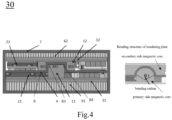
Fig. 4 is a sectional view of the power module of another embodiment of the present application; -
Fig. 5 is a sectional view of the power module of another embodiment of the present application; and -
Fig. 6 is a structural diagram of the insulating plate of the present application. - Additional aspects and advantages of the present application will be set forth in part in the following description, and will become apparent in part from the description, or may be learned through the practice of the present application.
- Exemplary embodiments will now be described more fully with reference to the accompanying drawing. However, the exemplary embodiments may be implemented in many forms and should not be construed as limited to the embodiments set forth herein. On the contrary, these exemplary embodiments are provided so that the present application will be comprehensive and complete, and will the conception of exemplary embodiments will be fully conveyed to those skilled in the art. The same reference numerals in the drawings denote the same or similar structures, and thus detailed descriptions thereof will be omitted.
- When introducing the elements/components/etc. described and/or illustrated herein, the terms "one", "a", "this", "the" and "at least one" are used to indicate the existence of one or more elements/components/etc. The terms "include", "comprise" and "provided with" are used to mean open inclusion and mean that there may be other elements/components/etc. in addition to the listed elements/components/etc. In addition, the terms "first", "second" and the like in the claims are only used as marks, and are not numerical restrictions on their objects.
-
Fig. 2A shows a 3D diagram of thepower module 10 in an embodiment of the present application.Fig. 2B is a sectional view of thepower module 10 as shown inFig. 2A along the straight line A-A. As shown inFig. 2B , thepower module 10 includes atransformer 1, a primaryside power element 21, a secondaryside power element 22, aninsulating plate 4 and aninsulating housing 7, wherein thetransformer 1, the primaryside power element 21, the secondaryside power element 22 andinsulating plate 4 are provided in theinsulating housing 7. Thetransformer 1 is provided in the middle of thepower module 10 along a first direction (for example, X direction), and includes a primary sidemagnetic core 11 and a secondary sidemagnetic core 12 buckled with each other. The primary sidemagnetic core 11 and the primaryside power element 21 form a primaryside conversion unit 31, and the secondary sidemagnetic core 12 and the secondaryside power element 22 form a secondaryside conversion unit 32. Theinsulating plate 4 is disposed between the primaryside conversion unit 31 and the secondaryside conversion unit 32, wherein theinsulating plate 4 includes a first area, and the first area is adaptively disposed between the primary sidemagnetic core 11 and the secondary sidemagnetic core 12. Specifically, in the present embodiment, the primary sidemagnetic core 11 and the secondary sidemagnetic core 12 are buckled with each other, the secondary sidemagnetic core 12 is U-shaped, and the primary sidemagnetic core 11 is I-shaped. Therefore, a buckle surface between the primary sidemagnetic core 11 and the secondary sidemagnetic core 12 is a curved plane. The first area is provided according to the shape of the buckle surface. As shown inFig. 2B , the first area includes a first side L1, a second side L2 and a third side L3. The first area has a plurality of buckling parts. The buckling part refers to the position where theinsulating plate 4 buckles. In the present embodiment, the first area includes two buckling parts, namely a first buckling part B1 and a second buckling part B2. The first buckling part B1 is a buckling angle formed by the first side L1 and the second side L2, and the second buckling part B2 is a buckling angle formed by the second side L2 and the third side L3, wherein, the first buckling part B1 and the second buckling part B2 buckles from the primary sidemagnetic core 11 to the secondary sidemagnetic core 12. In other embodiments, the first buckling part B1 and the second buckling part B2 can also buckle from the secondary sidemagnetic core 12 to the primary sidemagnetic core 11, which is not limited by the present application. In the present embodiment, each buckling part has a buckling angle θ1. Take the second buckling part B2 as an example, the second side L2, the third side L3 and the point P constitute the buckling angle of the second buckling part B2, and its buckling angle θ1 meets the following conditions: 0< θ1<180°, specifically, θ1 equals 90°. - In some embodiments, the secondary side
magnetic core 12 can be arc-shaped, so that the first area includes at least one bending part, which can bend from the secondary sidemagnetic core 12 to the primary sidemagnetic core 11 or from the primary sidemagnetic core 11 to the secondary sidemagnetic core 12. As shown inFig. 3 , the bending part bends from the primary sidemagnetic core 11 to the secondary sidemagnetic core 12, and the bending part has a bending radian θ2, and θ2 meets the following conditions: 0< θ2<360°; in some embodiments, θ2 meets the following conditions: 0<θ2<180°. In addition, the secondary sidemagnetic core 12 or the primary sidemagnetic core 11 can also be other feasible non-closed structures, and the first area includes the buckling part and/or bending part corresponding to the shape of the buckle surface of the primary sidemagnetic core 21 and the secondary sidemagnetic core 22. - In the present embodiment, as shown in
Fig. 6 , the insulatingplate 4 includes a first surface F1 and a second surface F2 provided opposite each other, and the first surface and the second surface are respectively provided with a semi-conducting layer. The semi-conducting layer is made of, for example, graphene, or carbon black, etc. - Please continue to refer to
Fig. 2B . In the present embodiment, the primaryside conversion unit 31 is a HV side of thepower module 10, and the HV side voltage is generally 10~35KV; the secondaryside conversion unit 32 is a LV side of thepower module 10, and the LV side voltage is generally 240~1000V. Thepower module 10 further includes aprimary side PCB 51, asecondary side PCB 52, a primary sideheat dissipation unit 61 and a secondary sideheat dissipation unit 62. The primaryside conversion unit 31 is provided on theprimary side PCB 51, and the secondaryside conversion unit 32 is provided on thesecondary side PCB 52, so that the electrical connection line between the conversion unit and the PCB is shorter. Theprimary side PCB 51 is provided on the primary sideheat dissipation unit 61, and thesecondary side PCB 52 is provided on the secondary sideheat dissipation unit 62. The centralized heat dissipation of the transformer and the power device is realized. The cooling air entering thepower module 10 can only pass through the primary sideheat dissipation unit 61 and the secondary sideheat dissipation unit 62, thus improving the reliability of the power module. In other embodiments, the primaryside conversion unit 31 and the primary sideheat dissipation unit 61 can be placed side by side, and the secondaryside conversion unit 32 and the secondary sideheat dissipation unit 62 can be placed side by side. - In the
power module 10, the insulatingplate 4 serves as both the insulation and the air gap of thetransformer 1. The buckle surface of the primary sidemagnetic core 11 and the secondary sidemagnetic core 12 is a curved plane. The buckle area (i.e. the air gap size) is large, so the demand for the magnetic core installation accuracy (i.e. the air gap tolerance) is low (± 0.5mm). In addition, the insulatingplate 4 is strengthened by buckling, which is not easy to deform. The thinner insulating plate can guarantee the tolerance, reduce the weight, and the deformation of the insulating plate is small. It also makes the subsequent shaping and correction process of the insulating plate simple and low cost. -
Fig. 3 is a sectional view of thepower module 20 of an embodiment of the present application. Thepower module 20 is provided with two transformers 1-1 and 1-2. Compared with thepower module 10 as shown inFig. 2B , the transformers 1-1 and 1-2 in thepower module 20 are arranged in different modes. As shown inFig. 3 , the transformers 1-1 and 1-2 are arranged in a second direction (for example, Z direction), and then provided at the first side S1 of thepower module 20. In other embodiments, the transformers 1-1 and 1-2 can be arranged in the second direction (for example, Z direction), and then provided at the second side S2 ofpower module 20, or in the middle of thepower module 20 in the first direction (for example, X direction). In some embodiments, the transformers 1-1 and 1-2 can also be arranged in the first direction (for example, X direction), and provided at the first side S1, the second side S2 of thepower module 20 or the middle of thepower module 20 in the first direction. The first direction (X direction), the second direction (Z direction) and the third direction (Y direction) are perpendicular to each other. In addition, the transformers 1-1 and 1-2 can also be provided at the first side S1 and the second side S2 of the power module respectively. Power elements are provided around the transformers 1-1 and 1-2. The primary side magnetic core 1-11 of the transformer 1-1, the primary side magnetic core 1-21 of the transformer 1-2 and a part of the power elements are fixed on theprimary side PCB 51, and theprimary side PCB 51 is tightly fixed on the primary sideheat dissipation unit 61; the secondary side magnetic core 1-12 of the transformer 1-1, the secondary side magnetic core 1-22 of the transformer 1-2 and another part of the power elements are fixed on thesecondary side PCB 52, and thesecondary side PCB 52 is tightly fixed on the secondaryside cooling unit 62. In other embodiments, when the number of transformers is single or more than two, the provision is similar to that of transformers 1-1 and 1-2, and will not be repeated here. - By arranging one or more transformers at the side of the power module, the power elements in the primary side conversion unit and the secondary side conversion unit are concentrated together. For example, the power elements are concentrated in the middle of the power module along the first direction (X direction), or are concentrated at the first side S1 or the second side S2. The connecting lines between the power elements do not need to cross the transformer, and the connecting lines are shorter. It is convenient for power circuit alignment connection, saves connection space, and reduces PCB size.
-
Fig. 4 is a sectional view of thepower module 30 in another embodiment of the present application. In the present embodiment, due to the changes in the position, size and other factors of the primary sidemagnetic core 11 and the secondary sidemagnetic core 12, the insulatingplate 4 between the primaryside conversion unit 31 and the secondaryside conversion unit 32 has a different shape from the insulatingplate 4 as shown inFig. 2B . Like the insulatingplate 4 as shown inFig. 2B , the insulatingplate 4 in the present embodiment also includes a first area, which is adaptively disposed between the primary sidemagnetic core 11 and the secondary sidemagnetic core 12, including a first side M1, a second side M2 and a third side M3. The first area includes two buckling parts, namely a third buckling part B3 (formed by a buckling angle formed by the first side M1 and the second side M2) and a fourth buckling part B4 (formed by a buckling angle formed by the second side M2 and the third side M3), wherein the third buckling part B3 and the fourth buckling part B4 both buckle from the primary sidemagnetic core 11 to the secondary sidemagnetic core 12. Furthermore, in other embodiments, the first area of the insulatingplate 4 includes a bending part, which bends from the primary sidemagnetic core 11 to the secondary sidemagnetic core 12. In other embodiments, the bending part can bend from the secondary sidemagnetic core 12 to the primary sidemagnetic core 11. It can be understood that in these embodiments, the first area can also include a plurality of buckling parts and/or a plurality of bending parts. The plurality of buckling parts and/or the plurality of bending parts buckle or bend in the same direction, which can be from the secondary sidemagnetic core 12 to the primary sidemagnetic core 11, or from the primary sidemagnetic core 11 to the secondary sidemagnetic core 12. - As shown in
Fig. 4 , the third buckling part B3 and the fourth bending part B4 bend from the primary sidemagnetic core 11 to the secondary sidemagnetic core 12, namely, the insulatingplate 4 includes a one-way bulge from the primary sidemagnetic core 11 to the secondary sidemagnetic core 12, and the optional height range of power element on the bulge side R of the insulatingplate 4 is wide, which is easier to match. The insulatingplate 4 has simple shape and is easy to process and manufacture. -
Fig. 5 is the sectional view of thepower module 40 of another embodiment of the present application. Thepower module 40 includes a first housing 7-1, and the primaryside conversion unit 31 is provided between the first housing 7-1 and the insulatingplate 4. Similar to the insulatingplate 4, the upper surface of the first housing 7-1 is provided with a semi-conducting layer or conducting layer, and the lower surface is also provided with a semi-conducting layer or conducting layer. The semi-conducting layer is made of graphene or carbon black, etc. The first housing 7-1 is made of insulating materials, such as epoxy resin or nylon, etc. The first housing 7-1 is fixedly connected with the insulatingplate 4 by screws or buckles. - The
power module 40 can only use the first housing 7-1, or further use a second housing 7-2. The secondaryside conversion unit 32 is provided between the second housing 7-2 and the insulatingplate 4. The second housing 7-2 is made of insulating materials or metal materials, and the insulating materials are, for example, epoxy resin or nylon, etc. In the present embodiment, the first housing 7-1 and the second housing 7-2 are U-shaped plates. The first housing 7-1, the second housing 7-2 and a part of the insulatingplate 4 form a cavity F. The cavity F is used to accommodate the primaryside conversion unit 31 and the secondaryside conversion unit 32. The first housing 7-1 and the second housing 7-2 are connected with the insulatingplate 4 by screws or buckles. In other embodiments, the first housing 7-1 and the second housing 7-2 can also be flat plates. In the present embodiment, the first housing 7-1, the second housing 7-2 and part of the insulating plate are molded by assembly into the insulatinghousing 7. In other embodiments, the insulatinghousing 7 can be integrally molded. - In the present embodiment, the primary side conversion unit and the secondary side conversion unit can be installed vertically through the open insulation housing structure, and the installation is simple and convenient. The provision of the semi-conducting layer on the insulating housing makes the whole electric field concentrated on the insulating housing, reducing the size of the primary conversion unit and the external LV room of the power module.
- To sum up, the power module provided by the present application can effectively improve the power density of the power unit and simplify the assembly and manufacturing process by adopting the innovative structural layout scheme, so as to better meet the market demand and improve product competitiveness.
- Exemplary embodiments of the present application have been specifically shown and described above. It should be understood that the present application is not limited to the disclosed embodiments. On the contrary, the present application is intended to cover various modifications and equivalent arrangements included in the spirit and scope of the appended claims.
Claims (13)
- A power module (10, 20, 30, 40), characterized in that the power module (10, 20, 30, 40) comprising:at least one transformer (1), each transformer comprising a primary side magnetic core (11) and a secondary side magnetic core (12);a primary side power element (21), the primary side magnetic core (11) and the primary side power element (21) forming a primary side conversion unit (31);a secondary side power element (22), the secondary side magnetic core (12) and the secondary side power element (22) forming a secondary side conversion unit (32); andan insulating plate (4), disposed between the primary side conversion unit (31) and the secondary side conversion unit (32), and comprising a first area, the first area being adaptively disposed between the primary side magnetic core (11) and the secondary side magnetic core (12), and the first area having at least one buckling part (B1, B2, B3, B4) and/or at least one bending part.
- The power module (10, 20, 30, 40) according to claim 1, wherein the insulating plate (4) comprises a first surface (F1) and a second surface (F2) provided opposite to each other, and the first surface (F1) and the second surface (F2) are respectively provided with semi-conducting layers.
- The power module (10, 20, 30, 40) according to claim 1, wherein,when the at least one transformer (1) comprises a single transformer, the single transformer is provided in the middle, the first side (S1) or the second side (S2) of the power module (10, 20, 30, 40) along a first direction (X direction);when the at least one transformer (1) comprises a plurality of transformers (1-1,1-2), the plurality of transformers (1-1,1-2) are simultaneously provided in the middle, the first side (S1) or the second side (S2) of the power module along the first direction (X direction), or respectively provided at the first side (S 1) and the second side (S2) of the power module (10, 20, 30, 40).
- The power module (10, 20, 30, 40) according to claim 1, further comprising a primary side PCB (51), a secondary side PCB (52), a primary side heat dissipation unit (61) and a secondary side heat dissipation unit (62), wherein the primary side conversion unit (31) is provided on the primary side PCB (51), and the secondary side conversion unit (32) is provided on the secondary side PCB (52); the primary side PCB (51) is provided on the primary side heat dissipation unit (61), and the secondary side PCB (52) is provided on the secondary side heat dissipation unit (62).
- The power module (10, 20, 30, 40) according to claim 1, wherein,the bending angle of the at least one buckling part (B1, B2, B3, B4) is θ1, which meets the following conditions: 0<θ1<180°; orthe buckling radian of the at least one bending part is θ2, which meets the following conditions: 0<θ2<360°.
- The power module (10, 20, 30, 40) according to claim 1, wherein,the at least one buckling part (B1, B2, B3, B4) buckles from the secondary side magnetic core (12) to the primary side magnetic core (11) or from the primary side magnetic core (11) to the secondary side magnetic core (12);the at least one bending part bends from the secondary side magnetic core (12) to the primary side magnetic core (11) or from the primary side magnetic core (11) to the secondary side magnetic core (12).
- The power module (10, 20, 30, 40) according to any of claims 1-6, further comprising an insulating housing (7), wherein the insulating housing (7) comprises a first housing (7-1), and the primary side conversion unit (31) is provided between the first housing (7-1) and the insulating plate (4).
- The power module (10, 20, 30, 40) according to claim 7, wherein an upper surface of the first housing (7-1) is provided with a semi-conducting layer or conducting layer, and a lower surface of the first housing (7-1) is provided with a semi-conducting layer or conducting layer.
- The power module (10, 20, 30, 40) according to claim 7, wherein the first housing (7-1) is made of an insulating material.
- The power module (10, 20, 30, 40) according to claim 7, wherein the insulating housing (7) further comprises a second housing (7-2), and the secondary side conversion unit (32) is provided between the second housing (7-2) and the insulating plate (4).
- The power module (10, 20, 30, 40) according to claim 10, wherein the second housing (7-2) is made of an insulating material or metal material, the primary side conversion unit (31) is a HV side of the power module (10, 20, 30, 40), and the secondary side conversion unit (32) is a LV side of the power module (10, 20, 30, 40).
- The power module (10, 20, 30, 40) according to claim 10, wherein the first housing (7-1), the second housing (7-2) and part of the insulating plate (4) form a cavity (F), and the cavity (F) is used to accommodate the primary side conversion unit (31) and the secondary side conversion unit (32).
- The power module (10 , 20 , 30 , 40) according to claim 10, wherein the insulating housing (7) further comprises a part of the insulating plate (4), wherein the insulating housing (7) is integrally molded; or, the insulating housing (7) is molded by assembly, and the first housing (7-1), the second housing (7-2) and the part of the insulating plate (4) are connected to form the insulating housing (7) by screws or buckles.
Applications Claiming Priority (1)
| Application Number | Priority Date | Filing Date | Title |
|---|---|---|---|
| CN202211714560.4A CN118265251A (en) | 2022-12-27 | 2022-12-27 | Power module |
Publications (1)
| Publication Number | Publication Date |
|---|---|
| EP4394821A1 true EP4394821A1 (en) | 2024-07-03 |
Family
ID=87426792
Family Applications (1)
| Application Number | Title | Priority Date | Filing Date |
|---|---|---|---|
| EP23186408.3A Pending EP4394821A1 (en) | 2022-12-27 | 2023-07-19 | Power module |
Country Status (3)
| Country | Link |
|---|---|
| US (1) | US20240215193A1 (en) |
| EP (1) | EP4394821A1 (en) |
| CN (1) | CN118265251A (en) |
Families Citing this family (1)
| Publication number | Priority date | Publication date | Assignee | Title |
|---|---|---|---|---|
| CN119421316A (en) * | 2024-09-26 | 2025-02-11 | 华为数字能源技术有限公司 | A power conversion device, a powertrain, and an electric vehicle |
Citations (3)
| Publication number | Priority date | Publication date | Assignee | Title |
|---|---|---|---|---|
| EP3817013A1 (en) * | 2019-10-31 | 2021-05-05 | Delta Electronics (Shanghai) Co., Ltd. | Power module |
| JP7026015B2 (en) * | 2018-07-17 | 2022-02-25 | 株式会社日立製作所 | Transformers, power converter units, and power converters |
| EP4009753A1 (en) * | 2020-11-06 | 2022-06-08 | Delta Electronics (Shanghai) Co., Ltd. | Power module and power conversion device |
Family Cites Families (9)
| Publication number | Priority date | Publication date | Assignee | Title |
|---|---|---|---|---|
| US6522233B1 (en) * | 2001-10-09 | 2003-02-18 | Tdk Corporation | Coil apparatus |
| JP5333504B2 (en) * | 2011-04-08 | 2013-11-06 | Tdk株式会社 | Bobbin for coil, coil component, and switching power supply device |
| US9373440B2 (en) * | 2014-02-28 | 2016-06-21 | Innotrans Technology Co., Ltd. | Composite transformer with a longer creepage distance |
| JP6814105B2 (en) * | 2017-06-30 | 2021-01-13 | 株式会社豊田自動織機 | Inductance element and LC filter |
| JP7133569B2 (en) * | 2018-01-17 | 2022-09-08 | 株式会社タムラ製作所 | Reactor |
| US20200258675A1 (en) * | 2019-02-08 | 2020-08-13 | Lear Corporation | Hybrid transformer for dc/dc converter |
| US11955754B2 (en) * | 2020-02-27 | 2024-04-09 | Rolls-Royce Corporation | Conductor for vehicle systems |
| EP3905283B1 (en) * | 2020-04-30 | 2023-11-22 | ABB E-mobility B.V. | Inductive fast charger |
| TWI712058B (en) * | 2020-09-08 | 2020-12-01 | 昱京科技股份有限公司 | Resonant transformer high pin structure |
-
2022
- 2022-12-27 CN CN202211714560.4A patent/CN118265251A/en active Pending
-
2023
- 2023-07-05 US US18/346,878 patent/US20240215193A1/en active Pending
- 2023-07-19 EP EP23186408.3A patent/EP4394821A1/en active Pending
Patent Citations (3)
| Publication number | Priority date | Publication date | Assignee | Title |
|---|---|---|---|---|
| JP7026015B2 (en) * | 2018-07-17 | 2022-02-25 | 株式会社日立製作所 | Transformers, power converter units, and power converters |
| EP3817013A1 (en) * | 2019-10-31 | 2021-05-05 | Delta Electronics (Shanghai) Co., Ltd. | Power module |
| EP4009753A1 (en) * | 2020-11-06 | 2022-06-08 | Delta Electronics (Shanghai) Co., Ltd. | Power module and power conversion device |
Also Published As
| Publication number | Publication date |
|---|---|
| CN118265251A (en) | 2024-06-28 |
| US20240215193A1 (en) | 2024-06-27 |
Similar Documents
| Publication | Publication Date | Title |
|---|---|---|
| US20240215193A1 (en) | Power module | |
| KR102816047B1 (en) | Transformer with Integrated Inductor | |
| US20210350974A1 (en) | Winding assembly and magnetic element | |
| US12027299B2 (en) | Winding assembly and magnetic element | |
| CN207977198U (en) | A kind of electronic transformer | |
| WO2021195924A1 (en) | Battery cell structure and battery | |
| CN207926424U (en) | Composite bus bar and frequency converter | |
| US20220208436A1 (en) | Power conversion module | |
| CN218569142U (en) | Dysmorphism electricity core integrated configuration and battery package thereof | |
| CN118737647A (en) | A high-power industrial control power supply vertical flat-plate transformer | |
| US20190318864A1 (en) | Planar transformer | |
| US20250329489A1 (en) | Planar electrical transformer and assembly | |
| CN211604895U (en) | A snap-on transformer skeleton | |
| US12573543B2 (en) | Magnetic integrated device | |
| US20240138070A1 (en) | Circuit board having composite magnetic components mounted thereon | |
| CN212750582U (en) | Be applied to 1.2kW switching power supply's planar transformer | |
| CN117612839A (en) | Vehicle-mounted integrated transformer and new energy automobile | |
| CN222980271U (en) | Vertical flat-plate transformer of high-power industrial control power supply | |
| CN201323128Y (en) | High-power planar transformer | |
| CN119207939B (en) | Superconductive belt material and coil framework cling type modularized runway-shaped coil | |
| CN223858020U (en) | Capacitor busbar, capacitor, power controller and power equipment | |
| US20250079070A1 (en) | Power module | |
| CN223898133U (en) | A multi-output high-voltage transformer | |
| CN222801545U (en) | An asymmetric magnetic integrated structure planar transformer | |
| CN224110102U (en) | A magnetic device |
Legal Events
| Date | Code | Title | Description |
|---|---|---|---|
| PUAI | Public reference made under article 153(3) epc to a published international application that has entered the european phase |
Free format text: ORIGINAL CODE: 0009012 |
|
| STAA | Information on the status of an ep patent application or granted ep patent |
Free format text: STATUS: THE APPLICATION HAS BEEN PUBLISHED |
|
| AK | Designated contracting states |
Kind code of ref document: A1 Designated state(s): AL AT BE BG CH CY CZ DE DK EE ES FI FR GB GR HR HU IE IS IT LI LT LU LV MC ME MK MT NL NO PL PT RO RS SE SI SK SM TR |
|
| STAA | Information on the status of an ep patent application or granted ep patent |
Free format text: STATUS: REQUEST FOR EXAMINATION WAS MADE |
|
| 17P | Request for examination filed |
Effective date: 20240814 |
|
| RBV | Designated contracting states (corrected) |
Designated state(s): AL AT BE BG CH CY CZ DE DK EE ES FI FR GB GR HR HU IE IS IT LI LT LU LV MC ME MK MT NL NO PL PT RO RS SE SI SK SM TR |