EP4394765A1 - Audio encoding and decoding method and apparatus, electronic device, computer readable storage medium, and computer program product - Google Patents
Audio encoding and decoding method and apparatus, electronic device, computer readable storage medium, and computer program product Download PDFInfo
- Publication number
- EP4394765A1 EP4394765A1 EP23822825.8A EP23822825A EP4394765A1 EP 4394765 A1 EP4394765 A1 EP 4394765A1 EP 23822825 A EP23822825 A EP 23822825A EP 4394765 A1 EP4394765 A1 EP 4394765A1
- Authority
- EP
- European Patent Office
- Prior art keywords
- predicted value
- feature
- vector
- signal
- band signal
- Prior art date
- Legal status (The legal status is an assumption and is not a legal conclusion. Google has not performed a legal analysis and makes no representation as to the accuracy of the status listed.)
- Pending
Links
Images





Classifications
-
- G—PHYSICS
- G10—MUSICAL INSTRUMENTS; ACOUSTICS
- G10L—SPEECH ANALYSIS TECHNIQUES OR SPEECH SYNTHESIS; SPEECH RECOGNITION; SPEECH OR VOICE PROCESSING TECHNIQUES; SPEECH OR AUDIO CODING OR DECODING
- G10L19/00—Speech or audio signals analysis-synthesis techniques for redundancy reduction, e.g. in vocoders; Coding or decoding of speech or audio signals, using source filter models or psychoacoustic analysis
- G10L19/008—Multichannel audio signal coding or decoding using interchannel correlation to reduce redundancy, e.g. joint-stereo, intensity-coding or matrixing
-
- G—PHYSICS
- G10—MUSICAL INSTRUMENTS; ACOUSTICS
- G10L—SPEECH ANALYSIS TECHNIQUES OR SPEECH SYNTHESIS; SPEECH RECOGNITION; SPEECH OR VOICE PROCESSING TECHNIQUES; SPEECH OR AUDIO CODING OR DECODING
- G10L19/00—Speech or audio signals analysis-synthesis techniques for redundancy reduction, e.g. in vocoders; Coding or decoding of speech or audio signals, using source filter models or psychoacoustic analysis
- G10L19/04—Speech or audio signals analysis-synthesis techniques for redundancy reduction, e.g. in vocoders; Coding or decoding of speech or audio signals, using source filter models or psychoacoustic analysis using predictive techniques
- G10L19/06—Determination or coding of the spectral characteristics, e.g. of the short-term prediction coefficients
-
- G—PHYSICS
- G10—MUSICAL INSTRUMENTS; ACOUSTICS
- G10L—SPEECH ANALYSIS TECHNIQUES OR SPEECH SYNTHESIS; SPEECH RECOGNITION; SPEECH OR VOICE PROCESSING TECHNIQUES; SPEECH OR AUDIO CODING OR DECODING
- G10L19/00—Speech or audio signals analysis-synthesis techniques for redundancy reduction, e.g. in vocoders; Coding or decoding of speech or audio signals, using source filter models or psychoacoustic analysis
- G10L19/02—Speech or audio signals analysis-synthesis techniques for redundancy reduction, e.g. in vocoders; Coding or decoding of speech or audio signals, using source filter models or psychoacoustic analysis using spectral analysis, e.g. transform vocoders or subband vocoders
- G10L19/0204—Speech or audio signals analysis-synthesis techniques for redundancy reduction, e.g. in vocoders; Coding or decoding of speech or audio signals, using source filter models or psychoacoustic analysis using spectral analysis, e.g. transform vocoders or subband vocoders using subband decomposition
-
- G—PHYSICS
- G10—MUSICAL INSTRUMENTS; ACOUSTICS
- G10L—SPEECH ANALYSIS TECHNIQUES OR SPEECH SYNTHESIS; SPEECH RECOGNITION; SPEECH OR VOICE PROCESSING TECHNIQUES; SPEECH OR AUDIO CODING OR DECODING
- G10L19/00—Speech or audio signals analysis-synthesis techniques for redundancy reduction, e.g. in vocoders; Coding or decoding of speech or audio signals, using source filter models or psychoacoustic analysis
- G10L19/04—Speech or audio signals analysis-synthesis techniques for redundancy reduction, e.g. in vocoders; Coding or decoding of speech or audio signals, using source filter models or psychoacoustic analysis using predictive techniques
- G10L19/16—Vocoder architecture
-
- G—PHYSICS
- G10—MUSICAL INSTRUMENTS; ACOUSTICS
- G10L—SPEECH ANALYSIS TECHNIQUES OR SPEECH SYNTHESIS; SPEECH RECOGNITION; SPEECH OR VOICE PROCESSING TECHNIQUES; SPEECH OR AUDIO CODING OR DECODING
- G10L21/00—Speech or voice signal processing techniques to produce another audible or non-audible signal, e.g. visual or tactile, in order to modify its quality or its intelligibility
- G10L21/02—Speech enhancement, e.g. noise reduction or echo cancellation
-
- G—PHYSICS
- G10—MUSICAL INSTRUMENTS; ACOUSTICS
- G10L—SPEECH ANALYSIS TECHNIQUES OR SPEECH SYNTHESIS; SPEECH RECOGNITION; SPEECH OR VOICE PROCESSING TECHNIQUES; SPEECH OR AUDIO CODING OR DECODING
- G10L21/00—Speech or voice signal processing techniques to produce another audible or non-audible signal, e.g. visual or tactile, in order to modify its quality or its intelligibility
- G10L21/02—Speech enhancement, e.g. noise reduction or echo cancellation
- G10L21/0208—Noise filtering
-
- G—PHYSICS
- G10—MUSICAL INSTRUMENTS; ACOUSTICS
- G10L—SPEECH ANALYSIS TECHNIQUES OR SPEECH SYNTHESIS; SPEECH RECOGNITION; SPEECH OR VOICE PROCESSING TECHNIQUES; SPEECH OR AUDIO CODING OR DECODING
- G10L19/00—Speech or audio signals analysis-synthesis techniques for redundancy reduction, e.g. in vocoders; Coding or decoding of speech or audio signals, using source filter models or psychoacoustic analysis
- G10L19/04—Speech or audio signals analysis-synthesis techniques for redundancy reduction, e.g. in vocoders; Coding or decoding of speech or audio signals, using source filter models or psychoacoustic analysis using predictive techniques
Definitions
- An embodiment of this application provides an audio decoding method, including:
- An embodiment of this application provides a computer-readable storage medium, having computer-executable instructions stored thereon, the computer-executable instructions, when being executed by a processor, implementing the audio coding method and the audio decoding method provided in embodiments of this application.
- Label extraction processing is performed on a predicted value of a feature vector obtained by decoding to obtain a label information vector, and signal reconstruction is performed with reference to the predicted value of the feature vector and the label information vector.
- the label information vector in comparison with signal reconstruction based on only the predicted value of the feature vector, because the label information vector only reflects core components in an audio signal, that is, the label information vector does not include acoustic interference such as noise, when signal reconstruction is performed with reference to the predicted value of the feature vector and the label information vector, the label information vector can be used for increasing a proportion of the core components in the audio signal to correspondingly reduce a proportion of acoustic interference such as noise, so that noise components included in the audio signal collected at an encoder side are effectively suppressed to achieve a signal enhancement effect, thereby improving quality of a reconstructed audio signal.
- Both compression rates of a speech encoder and a speech decoder provided in the related art can reach at least 10 times.
- original speech data of 10 MB only needs 1 MB to be transmitted after being compressed by the encoder.
- a bit rate of uncompressed version is 256 kilobits per second (kbps).
- the speech coding technology is used, even for lossy coding, in a bit rate range from 10 kbps to 20 kbps, quality of a reconstructed speech signal can be close to the uncompressed version, and even sound is considered to be no difference.
- a higher sampling rate service is needed, such as 32000 Hz ultra-wideband speech, the bit rate range needs to reach at least 30 kbps.
- the waveform speech coding is to directly code waveform of a speech signal.
- An advantage of this coding method is that quality of coding speech is high, but a compression rate is not high.
- the parametric speech coding refers to modeling a speech voicing process. What an encoder side needs to do is to extract a corresponding parameter of a to-be-transmitted speech signal.
- An advantage of the parametric speech coding is that the compression rate is extremely high, but a disadvantage is that quality of recovering speech is not high.
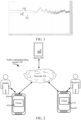
- FIG. 1 is a schematic diagram of frequency spectrum comparison under different bit rates according to an embodiment of this application, to demonstrate a relationship between compression bit rate and quality.
- a curve 101 is original speech, that is, an uncompressed audio signal.
- a curve 102 is of an effect of an OPUS encoder at 20 kbps.
- a curve 103 is of an effect of the OPUS encoder at 6 kbps. It can be learned from FIG. 1 that as a bit rate increases, a compressed signal becomes closer to the original signal.
- embodiments of this application provide an audio coding method and apparatus and an audio decoding method and apparatus, an electronic device, a computer-readable storage medium, and computer program product, capable of effectively suppressing acoustic interference in an audio signal while improving coding efficiency, thereby improving quality of a reconstructed audio signal.
- the following describes exemplary applications of the electronic device provided in all embodiments of this application.
- the electronic device provided in all embodiments of this application may be implemented as a terminal device, may be implemented as a server, or may be implemented collaboratively by a terminal device and a server.
- the following is an example of the audio coding method and the audio decoding method provided in all embodiments of this application being implemented collaboratively by a terminal device and a server.
- embodiments of this application may be implemented with help of a cloud technology.
- the cloud technology refers to a hosting technology that integrates resources such as hardware, software, and networks in a wide area network or a local area network, to implement data computing, storage, processing, and sharing.
- the memory 560 may be removable, non-removable, or a combination thereof.
- An example hardware device includes a solid-state memory, a hard disk drive, a DVD-ROM/CD-ROM drive, and the like.
- the memory 560 includes one or more storage devices physically located away from the processor 520.
- FIG. 4A is a schematic flowchart of an audio coding method according to an embodiment of this application.
- main steps performed at an encoder side include: Step 101: Obtain an audio signal.
- the first terminal device may code the audio signal to obtain the bitstream in the following manner.
- an analysis network such as a neural network
- the feature vector of the audio signal is quantized (such as vector quantization or scalar quantization) to obtain an index value of the feature vector.
- the index value of the feature vector is coded, for example, performing entropy coding on the index value of the feature vector, to obtain the bitstream.
- the first terminal device may further code the audio signal to obtain the bitstream in the following manner.
- a collected audio signal is decomposed to obtain N sub-band signals.
- N is an integer greater than 2.
- feature extraction processing is performed on each sub-band signal to obtain feature vectors of the sub-band signals.
- a neural network model can be invoked to perform feature extraction processing to obtain a feature vector of the sub-band signal.
- quantization coding is performed on the feature vectors of the sub-band signals respectively to obtain N sub-bitstreams.
- the first terminal device can send the bitstream to the server via a network.
- a transcoder can be deployed in the server to resolve an interconnection problem between a new encoder (which is an encoder that codes based on artificial intelligence, such as an NN encoder) and a conventional encoder (which is an encoder that codes based on transformation of time domain and frequency domain, such as a G.722 encoder).
- a new NN encoder is deployed in the first terminal device (that is, a transmitting end)
- a conventional decoder such as a G.722 decoder
- the second terminal device cannot correctly decode the bitstream sent by the first terminal device.
- Decoding processing and encoding processing are inverse processes. For example, when the encoder side uses entropy coding to code the feature vector of the audio signal to obtain the bitstream, the decoder side can correspondingly use entropy decoding to decode the received bitstream to obtain the index value of the feature vector of the audio signal.
- the second terminal device can first decode the low-frequency bitstream to obtain an index value (which is assumed to be index value 1) of the feature vector of the low-frequency sub-band signal, and then query the quantization table based on index value 1 to obtain the predicted value of the feature vector of the low-frequency sub-band signal.
- the second terminal device can first decode the high-frequency bitstream to obtain an index value (which is assumed to be an index value 2) of the feature vector of the high-frequency sub-band signal, and then query the quantization table based on the index value 2 to obtain the predicted value of the feature vector of the high-frequency sub-band signal.
- the label information vector is used for signal enhancement.
- a dimension of the label information vector is the same as a dimension of the predicted value of the feature vector.
- the predicted value of the feature vector and the label information vector can be spliced to achieve a signal enhancement effect of a reconstructed audio signal by increasing a proportion of core components.
- the predicted value of the feature vector and the label information vector are combined for signal reconstruction to enable all core components in the reconstructed audio signal to be enhanced, thereby improving quality of the reconstructed audio signal.
- the second terminal device can perform label extraction processing on the predicted value of the feature vector by invoking an enhancement network to obtain the label information vector.
- the enhancement network includes a convolutional layer, a neural network layer, a full-connection network layer, and an activation layer. The following describes a process of extracting the label information vector with reference to the foregoing structure of the enhancement network.
- FIG. 6A is a schematic flowchart of an audio decoding method according to an embodiment of this application.
- step 306 shown in FIG. 4C can be implemented by step 3061 to step 3064 shown in FIG. 6A .
- a description is carried out with reference to the steps shown in FIG. 6A .
- Step 3062 The second terminal device performs feature extraction processing on the first tensor to obtain a second tensor having a same dimension as the first tensor.
- Step 3063 The second terminal device performs full-connection processing on the second tensor to obtain a third tensor having a same dimension as the second tensor.
- the second terminal device can invoke the full-connection network layer included in the enhancement network to perform full-connection processing on the second tensor to obtain the third tensor having the same dimension as the second tensor.
- the dimension of the second tensor is 56x1
- a tensor of 56x1 is generated.
- the second terminal device can invoke the activation layer included in the enhancement network, that is, an activation function (for example, a ReLU function, a Sigmoid function, or a Tanh function) to activate the third tensor.
- an activation function for example, a ReLU function, a Sigmoid function, or a Tanh function
- the label information vector having the same dimension as the predicted value of the feature vector is generated.
- the dimension of the third tensor is 56x1
- the ReLU function is invoked to activate the third tensor, a label information vector having a dimension of 56x1 is obtained.
- the second terminal device can implement the foregoing performing label extraction processing on the predicted value of the feature vector of the low-frequency sub-band signal to obtain a first label information vector in the following manner.
- a first enhancement network is invoked to perform the following processing: performing convolution processing on the predicted value of the feature vector of the low-frequency sub-band signal to obtain a fourth tensor having a same dimension as the predicted value of the feature vector of the low-frequency sub-band signal; performing feature extraction processing on the fourth tensor to obtain a fifth tensor having a same dimension as the fourth tensor; performing full-connection processing on the fifth tensor to obtain a sixth tensor having a same dimension as the fifth tensor; and activating the sixth tensor to obtain the first label information vector.
- the second terminal device can implement the foregoing invoking, based on a predicted value of a feature vector of an i th sub-band signal, an i th enhancement network for label extraction processing to obtain an i th label information vector in the following manner.
- Step 307 The second terminal device performs signal reconstruction based on the predicted value of the feature vector and the label information vector to obtain a predicted value of the audio signal.
- the second terminal device can implement step 307 in the following manner.
- the predicted value of the feature vector and the label information vector are spliced to obtain a spliced vector.
- the spliced vector is compressed to obtain the predicted value of the audio signal.
- the compression processing can be implemented by one or more cascades of convolution processing, upsampling processing, and pooling processing, for example, can be implemented by the following step 3072 to step 3075.
- the predicted value of the audio signal includes predicted values corresponding to parameters such as frequency, wavelength, and amplitude of the audio signal.
- the second terminal device can invoke a synthesis network to perform signal reconstruction to obtain the predicted value of the audio signal.
- the synthesis network includes a first convolutional layer, an upsampling layer, a pooling layer, and a second convolutional layer. The following describes a process of signal reconstruction with reference to the foregoing structure of the synthesis network.
- FIG. 6B is a schematic flowchart of an audio decoding method according to an embodiment of this application.
- step 307 shown in FIG. 4C can be implemented by step 3071 to step 3075 shown in FIG. 6B .
- a description is carried out with reference to the steps shown in FIG. 6B .
- Step 3071 The second terminal device splices the predicted value of the feature vector and the label information vector to obtain a spliced vector.
- the second terminal device can splice the predicted value of the feature vector obtained based on step 305 and the label information vector obtained based on step 306 to obtain the spliced vector, and use the spliced vector as input of the synthesis network for signal reconstruction.
- Step 3072 The second terminal device performs first convolution processing on the spliced vector to obtain a convolution feature of the audio signal.
- the second terminal device can invoke the first convolutional layer included in the synthesis network (for example, a one-dimensional causal convolution) to perform convolution processing on the spliced vector to obtain the convolution feature of the audio signal.
- a tensor that is, the convolution feature of the audio signal having a dimension of 192x1 is obtained.
- Step 3073 The second terminal device upsamples the convolution feature to obtain an upsampled feature of the audio signal.
- the second terminal device can invoke the upsampling layer included in the synthesis network to upsample the convolution feature of the audio signal.
- the upsampling processing can be implemented by a plurality of cascaded decoding layers, and sampling factors of different decoding layers are different.
- the second terminal device can upsample the convolution feature of the audio signal to obtain the upsampled feature of the audio signal in the following manner.
- the convolution feature is upsampled by using the first decoding layer among the plurality of cascaded decoding layers.
- An upsampling result of the first decoding layer is outputted to a subsequent cascaded decoding layer, and the upsampling processing and the upsampling result output are continued by using the subsequent cascaded decoding layer until the output reaches the last decoding layer.
- An upsampling result outputted by the last decoding layer is used as the upsampled feature of the audio signal.
- the foregoing upsampling processing is a method of increasing a dimension of the convolution feature of the audio signal.
- the convolution feature of the audio signal can be upsampled by interpolation (such as bilinear interpolation) to obtain the upsampled feature of the audio signal.
- a dimension of the upsampled feature is larger than the dimension of the convolution feature.
- the dimension of the convolution feature can be increased by upsampling processing.
- a plurality of cascaded decoding layers are three cascaded decoding layers is used as an example.
- Three decoding layers having different upsampling factors can be cascaded.
- One or more dilated convolutions can be performed first.
- Each convolution kernel size is fixed at 1x3 and a stride rate at 1.
- a dilation rate of one or more dilated convolutions can be set according to requirements, for example, can be set to 3. Certainly, different dilation rates to be set for different dilated convolutions are not limited in all embodiments of this application.
- the Up_factors of the three decoding layers are set to 8, 5, and 4, respectively. This is equivalent to setting pooling factors of different sizes to play the role of upsampling.
- quantities of channels of the three decoding layers are set to 96, 48, and 24, respectively.
- the convolution feature such as a tensor of 192x1
- the convolution feature is converted into tensors of 96x8, 48x40, and 24 ⁇ 160 in sequence.
- the tensor of 24x160 can be used as the upsampled feature of the audio signal.
- Step 3074 The second terminal device performs pooling processing on the upsampled feature to obtain a pooled feature of the audio signal.
- the second terminal device can invoke the pooling layer in the synthesis network to perform pooling processing on the upsampled feature. For example, a pooling operation with a factor of 2 is performed on the upsampled feature to obtain the pooled feature of the audio signal.
- the upsampled feature of the audio signal is a tensor of 24x160, and after pooling processing (that is, post-processing shown in FIG. 14 ), a tensor (that is, the pooled feature of the audio signal) of 24x320 is generated.
- Step 3075 The second terminal device performs second convolution processing on the pooled feature to obtain the predicted value of the audio signal.
- the second terminal device can further invoke the second convolutional layer included in the synthesis network for the pooled feature of the audio signal. For example, a causal convolution shown in FIG. 14 is invoked to perform dilated convolution processing on the pooled feature to generate the predicted value of the audio signal.
- the second terminal device when the predicted value of the feature vector includes the predicted value of the feature vector of the low-frequency sub-band signal and the predicted value of the feature vector of the high-frequency sub-band signal, the second terminal device can further implement the foregoing step 307 in the following manner.
- the predicted value of the feature vector of the low-frequency sub-band signal and the first label information vector (that is, a label information vector obtained by performing label extraction processing on the predicted value of the feature vector of the low-frequency sub-band signal) are spliced to obtain a first spliced vector.
- a first synthesis network is invoked, based on the first spliced vector, for signal reconstruction to obtain a predicted value of the low-frequency sub-band signal.
- the predicted value of the feature vector of the high-frequency sub-band signal and the second label information vector (that is, a label information vector obtained by performing label extraction processing on the predicted value of the feature vector of the high-frequency sub-band signal) are spliced to obtain a second spliced vector.
- a second synthesis network is invoked, based on the second spliced vector, for signal reconstruction to obtain a predicted value of the high-frequency sub-band signal.
- the predicted value of the low-frequency sub-band signal and the predicted value of the high-frequency sub-band signal are synthesized to obtain the predicted value of the audio signal.
- the second terminal device can implement the foregoing invoking, based on the first spliced vector, a first synthesis network for signal reconstruction to obtain a predicted value of the low-frequency sub-band signal in the following manner.
- the first synthesis network is invoked to perform the following processing: performing first convolution processing on the first spliced vector to obtain a convolution feature of the low-frequency sub-band signal; upsampling the convolution feature of the low-frequency sub-band signal to obtain an upsampled feature of the low-frequency sub-band signal; performing pooling processing on the upsampled feature of the low-frequency sub-band signal to obtain a pooled feature of the low-frequency sub-band signal; and performing second convolution processing on the pooled feature of the low-frequency sub-band signal to obtain the predicted value of the low-frequency sub-band signal, the upsampling process being implemented by using a plurality of cascaded decoding layers, and sampling factors of different decoding layers being different.
- the second terminal device can implement the foregoing invoking, based on the second spliced vector, a second synthesis network for signal reconstruction to obtain a predicted value of the high-frequency sub-band signal in the following manner.
- the second synthesis network is invoked to perform the following processing: performing first convolution processing on the second spliced vector to obtain a convolution feature of the high-frequency sub-band signal; upsampling the convolution feature of the high-frequency sub-band signal to obtain an upsampled feature of the high-frequency sub-band signal; performing pooling processing on the upsampled feature of the high-frequency sub-band signal to obtain a pooled feature of the high-frequency sub-band signal; and performing second convolution processing on the pooled feature of the high-frequency sub-band signal to obtain the predicted value of the high-frequency sub-band signal, the upsampling process being implemented by using a plurality of cascaded decoding layers, and sampling factors of different decoding layers being different.
- the reconstruction process for the low-frequency sub-band signal (that is, a generation process of the predicted value of the low-frequency sub-band signal) and the reconstruction process for the high-frequency sub-band signal (that is, a generation process of the predicted value of the high-frequency sub-band signal) are similar to the reconstruction process of the audio signal (that is, a generation process of the predicted value of the audio signal), and are implemented with reference to the description in FIG. 6B . Details are not described again in embodiments of this application. Structures of the first synthesis network and the second synthesis network are similar to the structure of the foregoing synthesis network. Details are not described again in embodiments of this application.
- the second terminal device can further implement the foregoing step 307 in the following manner.
- the predicted values of the feature vectors corresponding to the N sub-band signals respectively and the N label information vectors are spliced one-to-one to obtain N spliced vectors.
- a j th synthesis network is invoked, based on a j th spliced vector, for signal reconstruction to obtain a predicted value of a j th sub-band signal, a value range of j satisfying that j is greater than or equal to 1 and is smaller than or equal to N.
- Predicted values corresponding to the N sub-band signals respectively are synthesized to obtain the predicted value of the audio signal.
- the second terminal device can implement the foregoing invoking, based on a j th spliced vector, a j th synthesis network for signal reconstruction to obtain a predicted value of a j th sub-band signal in the following manner.
- the second terminal device can use the predicted value of the audio signal obtained by the signal reconstruction as the decoding result of the bitstream, and send the decoding result to a built-in speaker of the second terminal device for playing.
- FIG. 8 is a schematic flowchart of an audio coding method and an audio decoding method according to an embodiment of this application.
- main steps at an encoder side include: For an input signal, such as an n th frame speech signal, denoted as x(n), an analysis network is invoked for feature extraction processing to obtain a low-dimensional feature vector, denoted as F(n).
- F(n) a dimension of the feature vector F(n) is smaller than a dimension of the input signal x(n), thereby reducing data volume.
- the estimated value F' ( n ) of the feature vector and the label information vector E ( n ) are combined to invoke a synthesis network (which is corresponding to an inverse process of the encoder side) for signal reconstruction, suppress noise components included in a speech signal collected at the encoder side, and generate an estimated signal value corresponding to the input signal x(n), which is denoted as X '( n ).
- the dilated convolution network and a QMF filter bank are first introduced.
- FIG. 9A is a schematic diagram of an ordinary convolution according to an embodiment of this application.
- FIG. 9B is a schematic diagram of a dilated convolution according to an embodiment of this application.
- the dilated convolution is proposed to increase a receptive field while keeping a size of a feature map unchanged, thereby avoiding errors caused by upsampling and downsampling.
- Convolution kernel sizes shown in FIG. 9A and FIG. 9B are both 3x3.
- a receptive field of the ordinary convolution shown in FIG. 9A is only 3, while a receptive field of the dilated convolution shown in FIG. 9B reaches 5.
- the receptive field of the ordinary convolution shown in FIG. 9A is 3, and a dilation rate is 1.
- the receptive field of the dilated convolution shown in FIG. 9B is 5 and a dilation rate is 2.
- the convolution kernel can also move on a plane similar to FIG. 9A or FIG. 9B .
- a concept of a stride rate is involved. For example, assuming that the convolution kernel strides by 1 frame each time, a corresponding stride rate is 1.
- a quantity of convolutional channels which is a quantity of parameters corresponding to a quantity of convolution kernels used for performing convolution analysis.
- a larger quantity of channels indicates more comprehensive signal analysis and higher accuracy.
- the larger quantity of channels indicates higher complexity. For example, for a tensor of 1x320, a 24-channel convolution operation can be used, and an output is a tensor of 24x320.
- a dilated convolution kernel size (for example, for a speech signal, the convolution kernel size is generally 1x3), a dilation rate, a stride rate, a quantity of channels, and the like can be defined according to actual application needs. This is not specifically limited in all embodiments of this application.
- the low-pass signal and the high-pass signal are synthesized by the QMF synthesis filter bank to recover a reconstructed signal having the sampling rate of Fs corresponding to the input signal.
- An objective of the analysis network is to generate, based on the input signal x(n), a feature vector F(n) having a lower dimension by invoking the analysis network (such as a neural network).
- a dimension of the input signal x(n) is 320
- a dimension of the feature vector F (n) is 56. From the perspective of data volume, feature extraction by the analysis network plays the role of "dimension reduction" and implements the function of data compression.
- the related networks (such as the analysis network and the synthesis network) at the encoder side and the decoder side can be jointly trained by collecting data to obtain optimal parameters.
- the related networks such as the analysis network and the synthesis network
- the decoder side can be jointly trained by collecting data to obtain optimal parameters.
- a user only needs to prepare data and set up a corresponding network structure. After a server completes training, a trained network can be put into use.
- the parameters of the analysis network and the synthesis network are trained, and only an implementation of a specific network input, network structure, and network output is disclosed. Engineers in the related fields can further modify the foregoing configuration according to actual conditions.
- the high-frequency sub-band signal is obtained by decomposing the input signal x (n), which is denoted as x HB (n).
- a second analysis network and a second synthesis module (which includes a second enhancement network and a second synthesis network) are invoked respectively to obtain an estimated value of the high-frequency sub-band signal at the decoder side, which is denoted as x HB ′ n .
- the processing flow for the high-frequency sub-band signal x HB (n) is similar to the processing flow for the low-frequency sub-band signal x LB (n), and can be implemented with reference to the processing flow of the low-frequency sub-band signal x LB (n). Details are not described again in embodiments of this application.
- the QMF performs signal decomposition.
- the QMF analysis filter (specifically referred to the 2-channel QMF here) can be invoked and downsampling is performed to obtain two parts of sub-band signals, a low-frequency sub-band signal x LB (n) and a high-frequency sub-band signal x HB (n), respectively.
- Effective bandwidth of the low-frequency sub-band signal x LB (n) is 0 kHz to 4 kHz.
- Effective bandwidth of the high-frequency sub-band signal x HB (n) is 4 kHz to 8 kHz.
- a quantity of sample points in each frame is 160.
- a received bitstream is decoded to obtain an estimated value F LB ′ n of the feature vector of the low-frequency sub-band signal and an estimated value F HB ′ n of the feature vector of the high-frequency sub-band signal.
- a first enhancement network and a second enhancement network are invoked to extract a label information vector.
- the first enhancement network shown in FIG. 18 can be invoked to collect label embedding information (that is, a label information vector of a low-frequency part) used for speech enhancement of the low-frequency part.
- the label embedding information is denoted as E LB (n), and is used for generating a clean low-frequency sub-band speech signal during decoding.
- the dimension of the outputted feature vector of the first analysis network at the encoder side can be referred to, to correspondingly adjust a structure of the first enhancement network shown in FIG. 18 , for example, including a quantity of parameters of the first enhancement network.
- the second enhancement network can be invoked to obtain a label information vector of a high-frequency part, which is denoted as E HB (n), for subsequent processes.
- the label information vectors of the two sub-band signals can be obtained, and are the label information vector E LB (n) of the low-frequency part and the label information vector E HB (n) of the high-frequency part, respectively.
- a first synthesis network and a second synthesis network are invoked for signal reconstruction.
- FIG. 19 is a schematic diagram of a structure of a first synthesis network according to an embodiment of this application.
- the first synthesis network can be invoked to generate an estimated value of a low-frequency sub-band signal, which is denoted as x' LB ( n ), based on an estimated value F LB ′ n of a feature vector of a low-frequency sub-band signal and a locally generated label information vector E LB (n) of a low-frequency part.
- x' LB ( n ) an estimated value of a low-frequency sub-band signal
- F LB ′ n a feature vector of a low-frequency sub-band signal
- E LB (n) a locally generated label information vector
- FIG. 19 only provides a specific configuration of the first synthesis network corresponding to the low-frequency part. An implementation form of the high-frequency part is similar. Details are not described again.
- an estimated value x' LB ( n ) of the low-frequency sub-band signal and an estimated value x' HB ( n ) of the high-frequency sub-band signal are generated.
- acoustic interference such as noise in the two sub-band signals is effectively suppressed.
- a harmonious combination of signal decomposition and a related signal processing technology as well as a deep neural network may enable coding efficiency to be significantly improved in comparison with a conventional signal processing solution.
- speech enhancement is implemented at a decoder side, so that an effect of reconstructing clean speech can be achieved at a low bit rate under acoustic interference such as noise.
- FIG. 20 A speech signal collected at an encoder side is mixed with a large amount of noise interference.
- a clean speech signal can be reconstructed at a decoder side, thereby improving quality of a voice call.
- the software module in the audio decoding apparatus 565 stored in the memory 560 may include: an obtaining module 5651, a decoding module 5652, a label extraction module 5653, a reconstruction module 5654, and a determining module 5655.
- the obtaining module 5651 is configured to obtain a bitstream, the bitstream being obtained by coding an audio signal.
- the decoding module 5652 is configured to decode the bitstream to obtain a predicted value of a feature vector of the audio signal.
- the label extraction module 5653 is configured to perform label extraction processing on the predicted value of the feature vector to obtain a label information vector, a dimension of the label information vector being the same as a dimension of the predicted value of the feature vector.
- the reconstruction module 5654 is configured to perform signal reconstruction based on the predicted value of the feature vector and the label information vector.
- the determining module 5655 is configured to use a predicted value of the audio signal obtained by the signal reconstruction as a decoding result of the bitstream.
- the decoding module 5652 is further configured to decode the bitstream to obtain an index value of a feature vector of the audio signal; and query a quantization table based on the index value to obtain the predicted value of the feature vector of the audio signal.
- the label extraction module 5653 is further configured to perform convolution processing on the predicted value of the feature vector to obtain a first tensor having a same dimension as the predicted value of the feature vector; perform feature extraction processing on the first tensor to obtain a second tensor having a same dimension as the first tensor; perform full-connection processing on the second tensor to obtain a third tensor having a same dimension as the second tensor; and activate the third tensor to obtain the label information vector.
- the reconstruction module 5654 is further configured to splice the predicted value of the feature vector and the label information vector to obtain a spliced vector; and perform first convolution processing on the spliced vector to obtain a convolution feature of the audio signal; upsample the convolution feature to obtain an upsampled feature of the audio signal; perform pooling processing on the upsampled feature to obtain a pooled feature of the audio signal; and perform second convolution processing on the pooled feature to obtain the predicted value of the audio signal.
- the upsampling process is implemented by using a plurality of cascaded decoding layers, and sampling factors of different decoding layers are different.
- the reconstruction module 5654 is further configured to upsample the convolution feature by using the first decoding layer among the plurality of cascaded decoding layers; output an upsampling result of the first decoding layer to a subsequent cascaded decoding layer, and continuing the upsampling processing and the upsampling result output by using the subsequent cascaded decoding layer until the output reaches the last decoding layer; and use an upsampling result outputted by the last decoding layer as the upsampled feature of the audio signal.
- the bitstream includes a low-frequency bitstream and a high-frequency bitstream, the low-frequency bitstream being obtained by coding a low-frequency sub-band signal obtained by decomposing the audio signal, and the high-frequency bitstream being obtained by coding a high-frequency sub-band signal obtained by decomposing the audio signal.
- the decoding module 5652 is further configured to decode the low-frequency bitstream to obtain a predicted value of a feature vector of the low-frequency sub-band signal; and configured to decode the high-frequency bitstream to obtain a predicted value of a feature vector of the high-frequency sub-band signal.
- the label extraction module 5653 is further configured to perform label extraction processing on the predicted value of the feature vector of the low-frequency sub-band signal to obtain a first label information vector, a dimension of the first label information vector being the same as a dimension of the predicted value of the feature vector of the low-frequency sub-band signal; and configured to perform label extraction processing on the predicted value of the feature vector of the high-frequency sub-band signal to obtain a second label information vector, a dimension of the second label information vector being the same as a dimension of the predicted value of the feature vector of the high-frequency sub-band signal.
- the label extraction module 5653 is configured to invoke a first enhancement network to perform the following processing: performing convolution processing on the predicted value of the feature vector of the low-frequency sub-band signal to obtain a fourth tensor having a same dimension as the predicted value of the feature vector of the low-frequency sub-band signal; performing feature extraction processing on the fourth tensor to obtain a fifth tensor having a same dimension as the fourth tensor; performing full-connection processing on the fifth tensor to obtain a sixth tensor having a same dimension as the fifth tensor; and activating the sixth tensor to obtain the first label information vector.
- the label extraction module 5653 is further configured to invoke a second enhancement network to perform the following processing: performing convolution processing on the predicted value of the feature vector of the high-frequency sub-band signal to obtain a seventh tensor having a same dimension as the predicted value of the feature vector of the high-frequency sub-band signal; performing feature extraction processing on the seventh tensor to obtain an eighth tensor having a same dimension as the seventh tensor; performing full-connection processing on the eighth tensor to obtain a ninth tensor having a same dimension as the eighth tensor; and activating the ninth tensor to obtain the second label information vector.
- the predicted value of the feature vector includes: the predicted value of the feature vector of the low-frequency sub-band signal and the predicted value of the feature vector of the high-frequency sub-band signal.
- the reconstruction module 5654 is further configured to splice the predicted value of the feature vector of the low-frequency sub-band signal and the first label information vector to obtain a first spliced vector; invoke, based on the first spliced vector, a first synthesis network for signal reconstruction to obtain a predicted value of the low-frequency sub-band signal; splice the predicted value of the feature vector of the high-frequency sub-band signal and the second label information vector to obtain a second spliced vector; invoke, based on the second spliced vector, a second synthesis network for signal reconstruction to obtain a predicted value of the high-frequency sub-band signal; and synthesize the predicted value of the low-frequency sub-band signal and the predicted value of the high-frequency sub-band signal to obtain the predicted value of the audio signal.
- the reconstruction module 5654 is further configured to invoke a first synthesis network to perform the following processing: performing first convolution processing on the first spliced vector to obtain a convolution feature of the low-frequency sub-band signal; upsampling the convolution feature to obtain an upsampled feature of the low-frequency sub-band signal; performing pooling processing on the upsampled feature to obtain a pooled feature of the low-frequency sub-band signal; and performing second convolution processing on the pooled feature to obtain the predicted value of the low-frequency sub-band signal, the upsampling process being implemented by using a plurality of cascaded decoding layers, and sampling factors of different decoding layers being different.
- the reconstruction module 5654 is further configured to invoke a second synthesis network to perform the following processing: performing first convolution processing on the second spliced vector to obtain a convolution feature of the high-frequency sub-band signal; upsampling the convolution feature to obtain an upsampled feature of the high-frequency sub-band signal; performing pooling processing on the upsampled feature to obtain a pooled feature of the high-frequency sub-band signal; and performing second convolution processing on the pooled feature to obtain the predicted value of the high-frequency sub-band signal, the upsampling process being implemented by using a plurality of cascaded decoding layers, and sampling factors of different decoding layers being different.
- the bitstream includes N sub-bitstreams, the N sub-bitstreams corresponding to different frequency bands and being obtained by coding N sub-band signals obtained by decomposing the audio signal, and N being an integer greater than 2.
- the decoding module 5652 is further configured to decode the N sub-bitstreams respectively to obtain predicted values of feature vectors corresponding to the N sub-band signals, respectively.
- the label extraction module 5653 is further configured to perform label extraction processing on the predicted values of the feature vectors corresponding to the N sub-band signals respectively to obtain N label information vectors used for signal enhancement, a dimension of each label information vector being the same as a dimension of the predicted value of the feature vector of the corresponding sub-band signal.
- the label extraction module 5653 is further configured to invoke, based on a predicted value of a feature vector of an i th sub-band signal, an i th enhancement network for label extraction processing to obtain an i th label information vector, a value range of i satisfying that i is greater than or equal to 1 and is smaller than or equal to N, and a dimension of the i th label information vector being the same as a dimension of the predicted value of the feature vector of the i th sub-band signal.
- the label extraction module 5653 is further configured to invoke an i th enhancement network to perform the following processing: performing convolution processing on the predicted value of the feature vector of the i th sub-band signal to obtain a tenth tensor having a same dimension as the predicted value of the feature vector of the i th sub-band signal; performing feature extraction processing on the tenth tensor to obtain an eleventh tensor having a same dimension as the tenth tensor; performing full-connection processing on the eleventh tensor to obtain a twelfth tensor having a same dimension as the eleventh tensor; and activating the twelfth tensor to obtain the i th label information vector.
- the reconstruction module 5654 is further configured to splice the predicted values of the feature vectors corresponding to the N sub-band signals respectively and the N label information vectors one-to-one to obtain N spliced vectors; invoke, based on a j th spliced vector, a j th synthesis network for signal reconstruction to obtain a predicted value of a j th sub-band signal, a value range of j satisfying that j is greater than or equal to 1 and is smaller than or equal to N; and synthesize predicted values corresponding to the N sub-band signals respectively to obtain the predicted value of the audio signal.
- the reconstruction module 5654 is further configured to invoke a j th synthesis network to perform the following processing: performing first convolution processing on the j th spliced vector to obtain a convolution feature of the j th sub-band signal; upsampling the convolution feature to obtain an upsampled feature of the j th sub-band signal; performing pooling processing on the upsampled feature to obtain a pooled feature of the j th sub-band signal; and performing second convolution processing on the pooled feature to obtain the predicted value of the j th sub-band signal, the upsampling process being implemented by using a plurality of cascaded decoding layers, and sampling factors of different decoding layers being different.
- An embodiment of this application provides a computer program product or a computer program, the computer program product or the computer program including computer instructions, which are stored in a computer-readable storage medium.
- a processor of a computer device reads the computer instructions from the computer-readable storage medium.
- the processor executes the computer instructions to enable the computer device to execute the audio coding method and the audio decoding method according to embodiments of this application.
- An embodiment of this application provides a computer-readable storage medium having computer-executable instructions stored thereon.
- the computer-executable instructions when being executed by a processor, enable the processor to execute the audio coding method and the audio decoding method according to embodiments of this application, for example, the audio coding method and the audio decoding method shown in FIG. 4C .
- the computer-readable storage medium may be a memory such as an FRAM, a ROM, a PROM, an EPROM, an EEPROM, a flash memory, a magnetic memory, a compact disc, or a CD-ROM; or may be a variety of devices including one of the foregoing memories or any combination.
- the computer-executable instructions may be in the form of programs, software, software modules, scripts, or code, written in any form of programming language (which includes compiled or interpreted languages, or declarative or procedural languages), and may be deployed in any form, which includes being deployed as a standalone program or as a module, component, subroutine, or another unit suitable for use in a computing environment.
- the executable instructions may, but do not necessarily, correspond to files in a file system, and may be stored in a part of the file for saving other programs or data, for example, stored in one or more scripts in a hyper text markup language (HTML) document, in a single file specifically used for the program of interest, or in a plurality of collaborative files (for example, files storing one or more modules, submodules, or code parts).
- HTML hyper text markup language
- the executable instructions may be deployed to be executed on a single electronic device, or on a plurality of electronic devices located in a single location, or on a plurality of electronic devices distributed in a plurality of locations and interconnected through a communication network.
Landscapes
- Engineering & Computer Science (AREA)
- Physics & Mathematics (AREA)
- Audiology, Speech & Language Pathology (AREA)
- Computational Linguistics (AREA)
- Signal Processing (AREA)
- Health & Medical Sciences (AREA)
- Human Computer Interaction (AREA)
- Acoustics & Sound (AREA)
- Multimedia (AREA)
- Spectroscopy & Molecular Physics (AREA)
- Quality & Reliability (AREA)
- Mathematical Physics (AREA)
- Compression, Expansion, Code Conversion, And Decoders (AREA)
Abstract
Description
- This application claims priority to
Chinese Patent Application No. 202210676984.X, filed on June 15, 2022 - This application relates to the field of communication technologies, and in particular, to an audio coding method and apparatus, an audio decoding method and apparatus, an electronic device, a computer-readable storage medium, and a computer program product.
- Due to the convenience and timeliness of speech communication, voice calls are increasingly used in applications, such as transmitting audio signals (such as speech signals) between conference participants in a network conference. In voice calls, the speech signals may be interfered by acoustic interference such as noise. The noise mixed in the speech signals causes the call quality to deteriorate, result in greatly affecting the listening experience of a user.
- However, in related art, there is no effective solution for how to enhance the speech signals to suppress the noise.
- Embodiments of this application provide an audio coding method and apparatus, an audio decoding method and apparatus, an electronic device, a computer-readable storage medium, and computer program product, capable of effectively suppressing acoustic interference in an audio signal, thereby improving quality of a reconstructed audio signal.
- Technical solutions in embodiments of this application are implemented as follows.
- An embodiment of this application provides an audio decoding method, including:
- obtaining a bitstream, the bitstream being obtained by coding an audio signal;
- decoding the bitstream to obtain a predicted value of a feature vector of the audio signal;
- performing label extraction processing on the predicted value of the feature vector to obtain a label information vector, a dimension of the label information vector being the same as a dimension of the predicted value of the feature vector;
- performing signal reconstruction based on the predicted value of the feature vector and the label information vector; and
- using a predicted value of the audio signal obtained by the signal reconstruction as a decoding result of the bitstream.
- An embodiment of this application provides an audio decoding apparatus, including:
- an obtaining module, configured to obtain a bitstream, the bitstream being obtained by coding an audio signal;
- a decoding module, configured to decode the bitstream to obtain a predicted value of a feature vector of the audio signal;
- a label extraction module, configured to perform label extraction processing on the predicted value of the feature vector to obtain a label information vector, a dimension of the label information vector being the same as a dimension of the predicted value of the feature vector;
- a reconstruction module, configured to perform signal reconstruction based on the predicted value of the feature vector and the label information vector; and
- a determining module, configured to use a predicted value of the audio signal obtained by the signal reconstruction as a decoding result of the bitstream.
- An embodiment of this application provides an audio coding method, including:
- obtaining an audio signal; and
- coding the audio signal to obtain a bitstream, the bitstream being used for an electronic device to perform the audio decoding method provided in embodiments of this application.
- An embodiment of this application provides an audio coding apparatus, including:
- an obtaining module, configured to obtain an audio signal; and
- a coding module, configured to code the audio signal to obtain a bitstream, the bitstream being used for an electronic device to perform the audio decoding method provided in embodiments of this application.
- An embodiment of this application provides an electronic device, including:
- a memory, configured to store computer-executable instructions; and
- a processor, configured to implement, when executing the computer-executable instructions stored in the memory, the audio coding method and the audio decoding method provided in embodiments of this application.
- An embodiment of this application provides a computer-readable storage medium, having computer-executable instructions stored thereon, the computer-executable instructions, when being executed by a processor, implementing the audio coding method and the audio decoding method provided in embodiments of this application.
- An embodiment of this application provides a computer program product, including a computer program product or computer-executable instructions, the computer program product or the computer-executable instructions, when being executed by a processor, implementing the audio coding method and the audio decoding method provided in embodiments of this application.
- Embodiments of this application have the following beneficial effects:
- Label extraction processing is performed on a predicted value of a feature vector obtained by decoding to obtain a label information vector, and signal reconstruction is performed with reference to the predicted value of the feature vector and the label information vector. In this way, in comparison with signal reconstruction based on only the predicted value of the feature vector, because the label information vector only reflects core components in an audio signal, that is, the label information vector does not include acoustic interference such as noise, when signal reconstruction is performed with reference to the predicted value of the feature vector and the label information vector, the label information vector can be used for increasing a proportion of the core components in the audio signal to correspondingly reduce a proportion of acoustic interference such as noise, so that noise components included in the audio signal collected at an encoder side are effectively suppressed to achieve a signal enhancement effect, thereby improving quality of a reconstructed audio signal.
-
-
FIG. 1 is a schematic diagram of frequency spectrum comparison under different bit rates according to an embodiment of this application. -
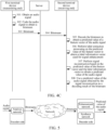
FIG. 2 is a schematic diagram of an architecture of an audio coding anddecoding system 100 according to an embodiment of this application. -
FIG. 3 is a schematic diagram of a structure of a secondterminal device 500 according to an embodiment of this application. -
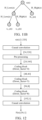
FIG. 4A is a schematic flowchart of an audio coding method according to an embodiment of this application. -
FIG. 4B is a schematic flowchart of an audio decoding method according to an embodiment of this application. -
FIG. 4C is a schematic flowchart of an audio coding method and an audio decoding method according to an embodiment of this application. -
FIG. 5 is a schematic diagram of structures of an encoder side and a decoder side according to an embodiment of this application. -
FIG. 6A and FIG. 6B are schematic flowcharts of an audio decoding method according to an embodiment of this application. -
FIG. 7 is a schematic diagram of an end-to-end speech communication link according to an embodiment of this application. -
FIG. 8 is a schematic flowchart of an audio coding method and an audio decoding method according to an embodiment of this application. -
FIG. 9A is a schematic diagram of an ordinary convolution according to an embodiment of this application. -
FIG. 9B is a schematic diagram of a dilated convolution according to an embodiment of this application. -
FIG. 10 is a schematic diagram of frequency spectrum response of a low-pass part and a high-pass part of a QMF analysis filter bank according to an embodiment of this application. -
FIG. 11a is a schematic diagram of a four-channel sub-band signal obtained based on a QMF filter bank according to an embodiment of this application. -
FIG. 11B is a schematic diagram of a three-channel sub-band signal obtained based on a QMF filter bank according to an embodiment of this application. -
FIG. 12 is a schematic diagram of a structure of an analysis network according to an embodiment of this application. -
FIG. 13 is a schematic diagram of a structure of an enhancement network according to an embodiment of this application. -
FIG. 14 is a schematic diagram of a structure of a synthesis network according to an embodiment of this application. -
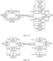
FIG. 15 is a schematic flowchart of an audio coding method and an audio decoding method according to an embodiment of this application. -
FIG. 16 is a schematic flowchart of an audio coding method and an audio decoding method according to an embodiment of this application. -
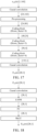
FIG. 17 is a schematic diagram of a structure of a first analysis network according to an embodiment of this application. -
FIG. 18 is a schematic diagram of a structure of a first enhancement network according to an embodiment of this application. -
FIG. 19 is a schematic diagram of a structure of a first synthesis network according to an embodiment of this application. -
FIG. 20 is a schematic diagram of comparison between a coding effect and a decoding effect. - To make the objectives, technical solutions, and advantages of this application clearer, the following describes this application in further detail with reference to the accompanying drawings. The described embodiments are not to be considered as a limitation to this application. All other embodiments obtained by a person of ordinary skill in the art without creative efforts shall fall within the protection scope of this application.
- In the following description, the term "some embodiments" describes subsets of all possible embodiments, but it may be understood that "some embodiments" may be the same subset or different subsets of all the possible embodiments, and can be combined with each other without conflict.
- It may be understood that in embodiments of the present disclosure including the embodiments of both the claims and the specification (hereinafter referred to as "all embodiments of the present disclosure", user information or other related data (for example, a speech signal sent by a user) may be involved. When embodiments of this application are applied to specific products or technologies, permission or consent of users is required. Moreover, collection, use, and processing of the related data need to comply with related laws, regulations, and standards of related countries and regions.
- In the following description, the terms "first", "second", and the like are merely intended to distinguish between similar objects rather than describe specific orders. It may be understood that, the terms "first", "second", and the like may, where permitted, be interchangeable in a particular order or sequence, so that embodiments of this application described herein may be performed in an order other than that illustrated or described herein.
- Unless otherwise defined, meanings of all technical and scientific terms used in this specification are the same as those usually understood by a person skilled in the art to which this application belongs. Terms used in the specification are merely intended to describe the objectives of embodiments of this application, but are not intended to limit this application.
- Before embodiments of this application are further described in detail, a description is made on terms in all embodiments of this application, and the terms in all embodiments of this application may be applicable to the following explanations.
- (1) Neural Network (NN): It is an algorithmic mathematical model that imitates behavior features of animal neural networks and performs distributed parallel information processing. This network relies on complexity of a system and adjusts interconnected relationships between a large quantity of internal nodes to achieve a purpose of processing information.
- (2) Deep Learning (DL): It is a new research direction in the field of machine learning (ML). The deep learning is to learn inherent laws and representation levels of sample data. Information obtained during these learning processes is of great help in interpretation of data such as words, images, and sounds. An ultimate objective of the deep learning is to enable machines to have the same analytical learning capabilities as humans and to recognize data such as text, images, and sounds.
- (3) Vector Quantization (VQ): It is an effective lossy compression technology based on Shannon's rate-distortion theory. A basic principle of the vector quantization is to replace an input vector with an index of a codeword in a codebook that best matches the input vector for transmission and storage, and only a simple table lookup operation is needed during decoding.
- (4) Scalar Quantization It is quantization on a scalar, that is, one-dimensional vector quantization. A dynamic range is divided into a plurality of small intervals, and each small intervals has a representative value. When an input signal falls into a specific interval, the input signal is quantized into the representative value.
- (5) Entropy Coding: It is a lossless coding method that does not lose any information according to the entropy principle during a coding process. It is also a key module in lossy coding and is located at the end of an encoder. Common entropy coding includes: Shannon coding, Huffman coding, Exp-Golomb coding, and arithmetic coding.
- (6) Quadrature Mirror Filter (QMF) Bank: It is a filter pair including analysis-synthesis. A QMF analysis filter bank is used for sub-band signal decomposition to reduce signal bandwidth, so that each sub-band signal can be processed smoothly by a channel. A QMF synthesis filter bank is used for synthesizing sub-band signals recovered from a decoder side, for example, an original audio signal is reconstructed by zero-value interpolation, band-pass filtering, and the like.
- A speech coding/decoding technology is a core technology in a communication service including remote audio and video calls. A speech coding technology simply is to use less network bandwidth resources to transmit as much speech information as possible. From the perspective of Shannon information theory, speech coding is a kind of source coding. An objective of the source coding is to compress data volume that needs to transmit information as much as possible on an encoder side, remove redundancy in the information, and recover the information at a decoder side in a lossless (or nearly lossless) way.
- Both compression rates of a speech encoder and a speech decoder provided in the related art can reach at least 10 times. To be specific, original speech data of 10 MB only needs 1 MB to be transmitted after being compressed by the encoder. This greatly reduces consumption of broadband resources needed to transmit information. For example, for a broadband speech signal having a sampling rate of 16000 Hz, if a 16-bit sampling depth is used, a bit rate of uncompressed version is 256 kilobits per second (kbps). If the speech coding technology is used, even for lossy coding, in a bit rate range from 10 kbps to 20 kbps, quality of a reconstructed speech signal can be close to the uncompressed version, and even sound is considered to be no difference. If a higher sampling rate service is needed, such as 32000 Hz ultra-wideband speech, the bit rate range needs to reach at least 30 kbps.
- Conventional speech coding solutions provided in the related art can generally be divided into three types according to the coding principle: waveform speech coding, parametric speech coding, and hybrid speech coding.
- The waveform speech coding is to directly code waveform of a speech signal. An advantage of this coding method is that quality of coding speech is high, but a compression rate is not high.
- The parametric speech coding refers to modeling a speech voicing process. What an encoder side needs to do is to extract a corresponding parameter of a to-be-transmitted speech signal. An advantage of the parametric speech coding is that the compression rate is extremely high, but a disadvantage is that quality of recovering speech is not high.
- The hybrid speech coding combines the foregoing two coding methods, and uses parameters to represent speech components on which the parametric speech coding can be used. The waveform speech coding is used on the remaining components that cannot be effectively expressed by parameters. The combination of the two coding methods can achieve high coding efficiency and high quality of recovered speech.
- Generally, the foregoing three coding principles are derived from classic speech signal modeling, also known as signal processing-based compression methods. Based on rate-distortion analysis and in combination with standardization experience over the past few decades, a bit rate of at least 0.75 bit/sample is recommended to provide ideal speech quality. For a wideband speech signal having a sampling rate of 16000 Hz, a bit rate is equivalent to 12 kbps. For example, the IETF OPUS standard recommends 16 kbps as a recommended bit rate for providing high-quality broadband voice calls.
- For example,
FIG. 1 is a schematic diagram of frequency spectrum comparison under different bit rates according to an embodiment of this application, to demonstrate a relationship between compression bit rate and quality. Acurve 101 is original speech, that is, an uncompressed audio signal. Acurve 102 is of an effect of an OPUS encoder at 20 kbps. Acurve 103 is of an effect of the OPUS encoder at 6 kbps. It can be learned fromFIG. 1 that as a bit rate increases, a compressed signal becomes closer to the original signal. - However, the applicant found that according to the foregoing solution provided in the related art, a conventional signal processing method is mainly used, and it is difficult to significantly reduce the bit rate while existing quality is maintained.
- In recent years, with the advancement of deep learning, the related art has also provided solutions for using artificial intelligence to reduce the bit rate.
- However, the applicant also found that: For an audio coding/decoding solution based on artificial intelligence, although the bit rate can be lower than 2 kbps, generation networks such as Wavenet are generally invoked, resulting in very high complexity on a decoder side, making the generation networks very challenging to use in a mobile terminal. Moreover, absolute quality is also significantly inferior to that of a conventional signal processing encoder. For an end-to-end NN-based coding/decoding solution, the bit rate is from 6 kbps to 10 kbps, and subjective quality is close to that of a conventional signal processing solution. However, deep learning networks are used at both encoder side and decoder side, resulting in very high complexity.
- In addition, whether it is a conventional signal processing solution or a deep neural network-based solution, only a speech signal can be compressed. However, actual speech communication is affected by acoustic interference such as noise. In other words, there is no solution in the related art that has both speech enhancement and a low bit rate and high quality compression effect.
- In view of this, embodiments of this application provide an audio coding method and apparatus and an audio decoding method and apparatus, an electronic device, a computer-readable storage medium, and computer program product, capable of effectively suppressing acoustic interference in an audio signal while improving coding efficiency, thereby improving quality of a reconstructed audio signal. The following describes exemplary applications of the electronic device provided in all embodiments of this application. The electronic device provided in all embodiments of this application may be implemented as a terminal device, may be implemented as a server, or may be implemented collaboratively by a terminal device and a server. The following is an example of the audio coding method and the audio decoding method provided in all embodiments of this application being implemented collaboratively by a terminal device and a server.
- For example,
FIG. 2 is a schematic diagram of an architecture of an audio coding anddecoding system 100 according to an embodiment of this application. To support an application that can effectively suppress acoustic interference in an audio signal while improving coding efficiency, and thereby improving quality of a reconstructed audio signal, as shown inFIG. 2 , the audio coding anddecoding system 100 includes: aserver 200, anetwork 300, a first terminal device 400 (that is, an encoder side), and a second terminal device 500 (that is, a decoder side). Thenetwork 300 may be a local area network, a wide area network, or a combination thereof. - In some embodiments, a
client 410 runs on the firstterminal device 400. Theclient 410 may be various types of clients, for example, including an instant messaging client, a network conferencing client, a livestreaming client, and a browser. In response to an audio collection instruction triggered by a sender (such as an initiator of a network conference, a streamer, or an initiator of a voice call), theclient 410 invokes a microphone in theterminal device 400 to collect an audio signal, and codes the collected audio signal to obtain a bitstream. Then, theclient 410 can send the bitstream to theserver 200 via thenetwork 300, so that theserver 200 sends the bitstream to the secondterminal device 500 associated with a receiver (such as a participant in a network conference, an audience, or a recipient of a voice call). After receiving the bitstream sent by theserver 200, aclient 510 can decode the bitstream to obtain a predicted value (also referred to as an estimated value) of a feature vector of the audio signal. Then, theclient 510 can further invoke an enhancement network to perform label extraction processing on the predicted value of the feature vector to obtain a label information vector used for signal enhancement, a dimension of the label information vector being the same as a dimension of the predicted value of the feature vector. Next, theclient 510 can invoke, based on the predicted value of the feature vector obtained by decoding and the label information vector obtained by the label extraction processing, a synthesis network for signal reconstruction, to obtain a predicted value of the audio signal, so that audio signal reconstruction is completed and noise components included in the audio signal collected at the encoder side are suppressed, thereby improving the quality of the reconstructed audio signal. - The audio coding method and the audio decoding method provided in all embodiments of this application can be widely used in various types of voice or video call application scenarios, such as on board voice implemented by an application running on an on board terminal, a voice call or a video call by an instant messaging client, a voice call in a game application, or a voice call in a network conferencing client. For example, speech enhancement can be performed at a receiving end of a voice call or a server that provides a speech communication service according to the audio decoding method provided in all embodiments of this application.
- A network conference scenario is used as an example. A network conference is an important link in online office. In the network conference, after a voice collection device (such as a microphone) of a participant in the network conference collects a speech signal of a speaker, the collected speech signal needs to be sent to other participants in the network conference. This process includes transmission and playback of the speech signal between a plurality of participants. If noise mixed in the speech signal is not processed, auditory experience of the conference participants is greatly affected. In this scenario, the audio decoding method provided in all embodiments of this application can be used to enhance the speech signal in the network conference, so that the speech signal heard by the conference participants is an enhanced speech signal. In other words, in a reconstructed speech signal, noise components in the speech signal collected at an encoder side are suppressed, thereby improving quality of a voice call in the network conference.
- In some other embodiments, embodiments of this application may be implemented with help of a cloud technology. The cloud technology refers to a hosting technology that integrates resources such as hardware, software, and networks in a wide area network or a local area network, to implement data computing, storage, processing, and sharing.
- The cloud technology is a general term of network technologies, information technologies, integration technologies, management platform technologies, application technologies, and other technologies applied to a cloud computing business model, and creates a resource pool to satisfy what is needed in a flexible and convenient manner. A cloud computing technology may be a backbone. A service interaction function between the foregoing
servers 200 can be implemented based on the cloud technology. - For example, the
server 200 shown inFIG. 2 may be an independent physical server, a server cluster or distributed system composed of a plurality of physical servers, or a cloud server providing basic cloud computing services, such as cloud services, cloud databases, cloud computing, cloud functions, network services, cloud communications, middleware services, domain name services, security services, content delivery networks (CDN), and big data and artificial intelligence platforms. Theterminal device 400 and theterminal device 500 shown inFIG. 2 may be a smartphone, a tablet computer, a notebook computer, a desktop computer, a smart speaker, a smartwatch, an on board terminal, or the like, but is not limited thereto. The terminal device (such as the firstterminal device 400 and the second terminal device 500) and theserver 200 may be connected directly or indirectly by wired or wireless communication, and this is not limited in all embodiments of this application. - In some embodiments, the terminal device (such as the second terminal device 500) or the
server 200 may implement the audio decoding method provided in all embodiments of this application by running a computer program. For example, the computer program may be a native program or a software module in an operating system, may be a native application (APP), that is, a program that needs to be installed in the operating system to run, such as a livestreaming APP, a network conferencing APP, or an instant messaging APP, or may be a small program, that is, a program that only needs to be downloaded to a browser environment to run. In summary, the foregoing computer program may be any form of application, module, or plug-in. - The following continues to describe a structure of the second
terminal device 500 shown inFIG. 2 .FIG. 3 is a schematic diagram of a structure of a secondterminal device 500 according to an embodiment of this application. The secondterminal device 500 shown inFIG. 3 includes: at least oneprocessor 520, amemory 560, at least onenetwork interface 530, and a user interface 540. Components in the secondterminal device 500 are coupled together by using abus system 550. It may be understood that, thebus system 550 is configured to implement connection and communication between the components. In addition to a data bus, thebus system 550 further includes a power bus, a control bus, and a state signal bus. However, for ease of clear description, all types of buses inFIG. 3 are marked as thebus system 550. - The
processor 520 may be an integrated circuit chip with a signal processing capability, for example, a general-purpose processor, a digital signal processor (DSP), another programmable logic device, a discrete gate or a transistor logic device, or a discrete hardware component. The general-purpose processor may be a microprocessor, any conventional processor, or the like. - The user interface 540 includes one or
more output devices 541 that enable presentation of media content. Theoutput device 541 includes one or more speakers and/or one or more visual displays. The user interface 540 further includes one ormore input apparatuses 542 including a user interface component that facilitates user input, for example, a keyboard, a mouse, a microphone, a touch screen display, a camera, and another input button and control. - The
memory 560 may be removable, non-removable, or a combination thereof. An example hardware device includes a solid-state memory, a hard disk drive, a DVD-ROM/CD-ROM drive, and the like. In one embodiment, thememory 560 includes one or more storage devices physically located away from theprocessor 520. - The
memory 560 may include a volatile memory or a non-volatile memory, or may include both a volatile memory and a non-volatile memory. The non-volatile memory may be a read-only memory (ROM), and the volatile memory may be a random-access memory (RAM). Thememory 560 described in all embodiments of this application aims to include any suitable type of memory. - In some embodiments, the
memory 560 can store data to support various operations, examples of the data include programs, modules, and data structures or subsets or supersets thereof. An example is as follows. - An
operating system 561 includes system programs for handling various basic system services and performing hardware-related tasks, for example, a frame layer, a core library layer, and a drive layer, used for implementing various basic services and processing hardware-based tasks. - A
network communication module 562 is configured to reach another computing device via one or more (which are wired or wireless) network interfaces 530. Anexample network interface 530 includes: Bluetooth, wireless fidelity (Wi-Fi), a universal serial bus (USB), or the like. - A
presentation module 563 is configured to enable presentation of information via one or more output devices 541 (for example, display screens and speakers) associated with the user interface 540 (for example, a user interface for operating a peripheral device and displaying content and information); - An input processing module 564 is configured to detect one or more user enters or interactions from one or
more input apparatuses 542 and translate the detected inputs or interactions. - In some embodiments, the audio decoding apparatus provided in all embodiments of this application may be implemented in a software manner.
FIG. 3 shows an audio decoding apparatus 565 stored in thememory 560, which may be software in a form of a program and a plug-in, and includes the following software modules: an obtainingmodule 5651, adecoding module 5652, alabel extraction module 5653, areconstruction module 5654, and a determiningmodule 5655. These modules are logical and therefore can be arbitrarily combined or further split based on implemented functions. The following describes the functions of each module. - The following describes the audio coding method and the audio decoding method provided in all embodiments of this application in detail with reference to exemplary applications of the terminal device provided in all embodiments of this application.
- For example,
FIG. 4A is a schematic flowchart of an audio coding method according to an embodiment of this application. As shown inFIG. 4A , main steps performed at an encoder side include: Step 101: Obtain an audio signal. Step 102: Code the audio signal to obtain a bitstream. - For example,
FIG. 4B is a schematic flowchart of an audio decoding method according to an embodiment of this application. As shown inFIG. 4B , main steps performed at a decoder side include: Step 201: Obtain a bitstream. Step 202: Decode the bitstream to obtain a predicted value of a feature vector of an audio signal. Step 203: Perform label extraction processing on the predicted value of the feature vector to obtain a label information vector. Step 204: Perform signal reconstruction based on the predicted value of the feature vector and the label information vector. Step 205: Use a predicted value of the audio signal obtained by the signal reconstruction as a decoding result of the bitstream. - The following uses a conference system based on Voice over Internet Protocol (VoIP) as an example. From the perspective of interaction between a first terminal device (that is, an encoder side), a server, and a second terminal device (that is, a decoder side), the audio coding method and the audio decoding method provided in all embodiments of this application are described in detail.
- For example,
FIG. 4C is a schematic flowchart of an audio coding method and an audio decoding method according to an embodiment of this application. A description is carried out with reference to steps shown inFIG. 4C . - Steps performed by the terminal device may be performed by a client running on the terminal device. For ease of description, embodiments of this application do not make a specific distinction between the terminal device and the client running on the terminal device. In addition, the audio coding method and the audio decoding method provided in all embodiments of this application may be performed by various forms of computer programs running on the terminal device but is not limited to being performed by the client running on the terminal device, or may be performed by the foregoing
operating system 561, software module, script, or small program. Therefore, an example of the client below is not to be regarded as limiting embodiments of this application. - Before describing
FIG. 4C , structures of the encoder side and the decoder side are described first. - For example,
FIG. 5 is a schematic diagram of structures of an encoder side and a decoder side according to an embodiment of this application. As shown inFIG. 5 , the encoder side includes an analysis network, which is used for performing feature extraction processing on an input audio signal to obtain a feature vector of the audio signal. Then, quantization coding processing is performed on the feature vector of the audio signal to obtain a bitstream. The decoder side includes an enhancement network and a synthesis network. After the received bitstream is decoded and a predicted value of the feature vector of the audio signal is obtained, the enhancement network can be invoked to perform label extraction processing on the predicted value of the feature vector of the audio signal to obtain a label information vector, and then the synthesis network can be invoked, based on the label information vector and the predicted value of the feature vector, for signal reconstruction to obtain a predicted value of the audio signal. - The following describes the audio coding method and the audio decoding method provided in all embodiments of this application in detail with reference to the foregoing structures of the encoder side and the decoder side.
- Step 301: A first terminal device obtains an audio signal.
- In some embodiments, in response to an audio collection instruction triggered by a user, the first terminal device invokes an audio collection device (such as a built-in microphone or an external microphone in the first terminal device) to collect an audio signal to obtain the audio signal, for example, which may be a speech signal of a speaker in a network conference scenario, a speech signal of a streamer in a livestreaming scenario, or the like.
- For example, the network conference scenario is used as an example. When a network conference APP running on the first terminal device receives a click/tap operation of the user (such as an initiator of the network conference) on an "Open Microphone" button displayed in a human-computer interaction interface, a microphone (or microphone array) provided by the first terminal device is invoked to collect the speech signal sent by the user, to obtain the speech signal of the initiator of the network conference.
- Step 302: The first terminal device codes the audio signal to obtain a bitstream.
- In some embodiments, after invoking the microphone to collect the audio signal, the first terminal device may code the audio signal to obtain the bitstream in the following manner. First, an analysis network (such as a neural network) is invoked to perform feature extraction processing on the audio signal to obtain a feature vector of the audio signal. Then, the feature vector of the audio signal is quantized (such as vector quantization or scalar quantization) to obtain an index value of the feature vector. Finally, the index value of the feature vector is coded, for example, performing entropy coding on the index value of the feature vector, to obtain the bitstream.
- For example, the foregoing vector quantization refers to a process of coding points in vector space with a limited subset thereof. In vector quantization coding, the key is establishment of a codebook (or quantization table) and a search algorithm of a codeword. After the feature vector of the audio signal is obtained, a codebook can be queried first for the codeword that best matches the feature vector of the audio signal, and then an index value of the codeword obtained by the query is used as the index value of the feature vector. In other words, the index value of the codeword in the codebook that best matches the feature vector of the audio signal is used to replace the feature vector of the audio signal for transmission and storage.
- For example, the foregoing scalar quantization refers to one-dimensional vector quantization. An entire dynamic range is divided into a plurality of small intervals, and each small interval has a representative value. During quantization, a signal value falling into the small interval is replaced by the entire representative value, or is quantized to this representative value. A signal in this case is one-dimensional, so that the quantization is referred to as scalar quantization. For example, assuming that the feature vector of the audio signal falls into a
small interval 2, a representative value corresponding to thesmall interval 2 can be used as the index value of the feature vector. - For example, the first terminal device can perform feature extraction processing on the audio signal to obtain the feature vector of the audio signal in the following manner. First, convolution processing (such as causal convolution processing) is performed on the audio signal to obtain a convolution feature of the audio signal. Next, pooling processing is performed on the convolution feature of the audio signal to obtain a pooled feature of the audio signal. Then, the pooled feature of the audio signal is downsampled to obtain a downsampled feature of the audio signal. Finally, convolution processing is performed on the downsampled feature of the audio signal to obtain the feature vector of the audio signal.
- For example, the essence of the foregoing pooling processing is dimension reduction. After a convolutional layer, a dimension of a feature outputted by the convolutional layer is reduced by pooling, to reduce the overfitting phenomenon during reducing network parameters and calculation costs. The pooling includes max pooling and average pooling. The max pooling refers to taking a point having the largest value in a local receptive field, that is, reducing data volume based on the maximum value. The average pooling refers to taking the average of values in the local receptive field.
- In some other embodiments, the first terminal device may further code the audio signal to obtain the bitstream in the following manner. A collected audio signal is decomposed, for example, is decomposed by two-channel QMF analysis filter bank to obtain a low-frequency sub-band signal and a high-frequency sub-band signal. Then, feature extraction processing is performed on the low-frequency sub-band signal and the high-frequency sub-band signal, respectively, to correspondingly obtain a feature vector of the low-frequency sub-band signal and a feature vector of the high-frequency sub-band signal. Then, quantization coding is performed on the feature vector of the low-frequency sub-band signal to obtain a low-frequency bitstream of the audio signal. Quantization coding is performed on the feature vector of the high-frequency sub-band signal to obtain a high-frequency bitstream of the audio signal. In this way, the audio signal is first decomposed, and then the quantization coding is performed respectively on the low-frequency sub-band signal and the high-frequency sub-band signal obtained by the decomposition, to effectively reduce information loss caused by compression.
- For example, the first terminal device can decompose the audio signal to obtain the low-frequency sub-band signal and the high-frequency sub-band signal in the following manner. First, the audio signal is sampled to obtain a sampled signal. The sampled signal includes a plurality of collected sample points. Next, low-pass filtering processing is performed on the sampled signal to obtain a low-pass filtered signal. Then, the low-pass filtered signal is downsampled to obtain the low-frequency sub-band signal. Similarly, high-pass filtering processing is performed on the sampled signal to obtain a high-pass filtered signal, and the high-pass filtered signal is downsampled to obtain the high-frequency sub-band signal.
- For example, the foregoing low-pass filtering is a filtering method. A rule is that low-frequency signals can pass normally, while high-frequency signals that exceed a set threshold are blocked and weakened. The low-pass filtering can be simply thought of as: A frequency point is set, and when a signal frequency is higher than this frequency, the signal cannot pass. For a digital signal, this frequency point is also a cut-off frequency. When a frequency domain is higher than this cut-off frequency, all values are assigned to 0. Because all low-frequency signals are allowed to pass in this process, the process is referred to as low-pass filtering.
- For example, the foregoing high-pass filtering is a filtering method. A rule is that high-frequency signals can pass normally, while low-frequency signals below a set threshold are blocked and weakened. The high-pass filtering can be simply thought of as: A frequency point is set, and when a signal frequency is lower than this frequency, the signal cannot pass. For a digital signal, this frequency point is also referred to as a cut-off frequency. When a frequency domain is lower than this cut-off frequency, all values are assigned to 0. Because all high-frequency signals are allowed to pass in this process, the process is referred to as high-pass filtering.
- For example, the foregoing downsampling processing is a method of reducing a quantity of sampling points. For example, the downsampling processing can be performed by taking values at intervals to obtain a low-frequency sub-band signal. For example, for a plurality of sampled signals included in the low-pass filtered signal, selection can be performed once every three bits, that is, a first bit sampled signal, a fourth bit sampled signal, a seventh bit sampled signal, and the like are selected, to obtain low-frequency sub-band signals.
- In some embodiments, the first terminal device may further code the audio signal to obtain the bitstream in the following manner. First, a collected audio signal is decomposed to obtain N sub-band signals. N is an integer greater than 2. Next, feature extraction processing is performed on each sub-band signal to obtain feature vectors of the sub-band signals. For example, for each sub-band signal obtained by the decomposition, a neural network model can be invoked to perform feature extraction processing to obtain a feature vector of the sub-band signal. Then, quantization coding is performed on the feature vectors of the sub-band signals respectively to obtain N sub-bitstreams.
- For example, the foregoing decomposition processing on the collected audio signal to obtain the N sub-band signals can be implemented in the following manner. For example, decomposition processing can be performed by four-channel QMF analysis filter bank to obtain four sub-band signals. For example, first, low-pass filtering and high-pass filtering can be performed on the audio signal to obtain a low-frequency sub-band signal and a high-frequency sub-band signal. Then, low-pass filtering and high-pass filtering can be performed again on the low-frequency sub-band signal to correspondingly obtain
sub-band signal 1 andsub-band signal 2. Similarly, low-pass filtering and high-pass filtering can be performed again on the high-frequency sub-band signal obtained by decomposition to correspondingly obtainsub-band signal 3 andsub-band signal 4. In this way, two layers of 2-channel QMF analysis filtering are iterated to decompose the audio signal into four sub-band signals. - Step 303: The first terminal device sends the bitstream to a server.
- In some embodiments, after coding the collected audio signal to obtain the bitstream, the first terminal device can send the bitstream to the server via a network.
- Step 304: The server sends the bitstream to a second terminal device.
- In some embodiments, after receiving the bitstream sent by the first terminal device (that is, the encoder side, such as a terminal device associated with an initiator of a network conference), the server can send the bitstream to the second terminal device (that is, the decoder side, such as a terminal device associated with a participant of the network conference) via a network.
- In some other embodiments, considering forward compatibility, a transcoder can be deployed in the server to resolve an interconnection problem between a new encoder (which is an encoder that codes based on artificial intelligence, such as an NN encoder) and a conventional encoder (which is an encoder that codes based on transformation of time domain and frequency domain, such as a G.722 encoder). For example, if a new NN encoder is deployed in the first terminal device (that is, a transmitting end), and a conventional decoder (such as a G.722 decoder) is deployed in the second terminal device (that is, a receiving end), the second terminal device cannot correctly decode the bitstream sent by the first terminal device. For the foregoing situation, the transcoder can be deployed in the server. For example, after receiving the bitstream that is coded based on the NN encoder and that is sent by the first terminal device, the server can first invoke the NN decoder to generate an audio signal, and then invoke the conventional encoder (such as a G.722 encoder) to generate a specific bitstream. In this way, the second terminal device can decode correctly. In other words, a problem that the decoder side cannot decode correctly due to inconsistent versions of the encoder deployed on the encoder side and the decoder deployed on the decoder side can be avoided, thereby improving compatibility in a coding and decoding process.
- Step 305: The second terminal device decodes the bitstream to obtain a predicted value of a feature vector of the audio signal.
- In some embodiments, the second terminal device can implement step 305 in the following manner. First, the bitstream is decoded to obtain an index value of the feature vector of the audio signal. Then, a quantization table is queried based on the index value to obtain the predicted value of the feature vector of the audio signal. For example, when the encoder side uses an index value of a codeword in the quantization table that best matches the feature vector of the audio signal to replace the feature vector for subsequent coding, after decoding the bitstream to obtain the index value, the decoder side can perform a simple table lookup operation based on the index value to obtain the predicted value of the feature vector of the audio signal.
- Decoding processing and encoding processing are inverse processes. For example, when the encoder side uses entropy coding to code the feature vector of the audio signal to obtain the bitstream, the decoder side can correspondingly use entropy decoding to decode the received bitstream to obtain the index value of the feature vector of the audio signal.
- In some other embodiments, when the bitstream includes a low-frequency bitstream and a high-frequency bitstream, the second terminal device can further implement the foregoing step 305 in the following manner. The low-frequency bitstream is decoded to obtain a predicted value of a feature vector of the low-frequency sub-band signal. The high-frequency bitstream is decoded to obtain a predicted value of a feature vector of the high-frequency sub-band signal. The low-frequency bitstream is obtained by coding the low-frequency sub-band signal obtained by decomposing the audio signal, and the high-frequency bitstream is obtained by coding the high-frequency sub-band signal obtained by decomposing the audio signal. The low-frequency bitstream is used as an example. When the encoder side uses entropy coding to code the feature vector of the low-frequency sub-band signal, the decoder side can use corresponding entropy decoding to decode the low-frequency bitstream.
- For example, for the low-frequency bitstream, the second terminal device can first decode the low-frequency bitstream to obtain an index value (which is assumed to be index value 1) of the feature vector of the low-frequency sub-band signal, and then query the quantization table based on
index value 1 to obtain the predicted value of the feature vector of the low-frequency sub-band signal. Similarly, for the high-frequency bitstream, the second terminal device can first decode the high-frequency bitstream to obtain an index value (which is assumed to be an index value 2) of the feature vector of the high-frequency sub-band signal, and then query the quantization table based on theindex value 2 to obtain the predicted value of the feature vector of the high-frequency sub-band signal. - In some embodiments, when the bitstream includes N sub-bitstreams, the N sub-bitstreams corresponding to different frequency bands and being obtained by coding the N sub-band signals obtained by decomposing the audio signal, and N being an integer greater than 2, the second terminal device can further implement the foregoing step 305 in the following manner. The N sub-bitstreams are decoded respectively to obtain predicted values of feature vectors corresponding to the N sub-band signals, respectively. A decoding process for the N sub-bitstreams here can be implemented with reference to the foregoing decoding process for the low-frequency bitstream or the high-frequency bitstream. Details are not described again in embodiments of this application.
- For example, that the N sub-bitstreams are four sub-bitstreams, namely sub-bitstream 1,
sub-bitstream 2,sub-bitstream 3, andsub-bitstream 4 is used as an example. Sub-bitstream 1 is obtained by codingsub-band signal 1,sub-bitstream 2 is obtained by codingsub-band signal 2,sub-bitstream 3 is obtained by codingsub-band signal 3, andsub-bitstream 4 is obtained by codingsub-band signal 4. After receiving these four sub-bitstreams, the second terminal device can decode the four sub-bitstreams respectively to correspondingly obtain predicted values of feature vectors corresponding to the four sub-band signals, for example, including a predicted value of a feature vector ofsub-band signal 1, a predicted value of a feature vector ofsub-band signal 2, a predicted value of a feature vector ofsub-band signal 3, and a predicted value of a feature vector ofsub-band signal 4. - Step 306: The second terminal device performs label extraction processing on the predicted value of the feature vector to obtain a label information vector.
- The label information vector is used for signal enhancement. In addition, a dimension of the label information vector is the same as a dimension of the predicted value of the feature vector. In this way, during subsequent signal reconstruction, the predicted value of the feature vector and the label information vector can be spliced to achieve a signal enhancement effect of a reconstructed audio signal by increasing a proportion of core components. In other words, the predicted value of the feature vector and the label information vector are combined for signal reconstruction to enable all core components in the reconstructed audio signal to be enhanced, thereby improving quality of the reconstructed audio signal.
- In some embodiments, the second terminal device can perform label extraction processing on the predicted value of the feature vector by invoking an enhancement network to obtain the label information vector. The enhancement network includes a convolutional layer, a neural network layer, a full-connection network layer, and an activation layer. The following describes a process of extracting the label information vector with reference to the foregoing structure of the enhancement network.
- For example,
FIG. 6A is a schematic flowchart of an audio decoding method according to an embodiment of this application. As shown inFIG. 6A , step 306 shown inFIG. 4C can be implemented bystep 3061 to step 3064 shown inFIG. 6A . A description is carried out with reference to the steps shown inFIG. 6A . - Step 3061: The second terminal device performs convolution processing on the predicted value of the feature vector to obtain a first tensor having a same dimension as the predicted value of the feature vector.
- In some embodiments, the second terminal device can use the predicted value of the feature vector obtained in step 305 as input, invoke the convolutional layer (for example, a one-dimensional causal convolution) included in the enhancement network, and generate the first tensor (where a tensor is a quantity that includes values in a plurality of dimensions) having the same dimension as the predicted value of the feature vector. For example, as shown in
FIG. 13 , the dimension of the predicted value of the feature vector is 56x1, and after causal convolution processing, a tensor of 56x1 is generated. - Step 3062: The second terminal device performs feature extraction processing on the first tensor to obtain a second tensor having a same dimension as the first tensor.
- In some embodiments, by using the neural network layer (such as a long short-term memory network and a temporal recurrent neural network) included in the enhancement network, feature extraction processing can be performed on the first tensor obtained by causal convolution processing, to generate the second tensor having the same dimension as the first tensor. For example, as shown in
FIG. 13 , the dimension of the first tensor is 56x1, and after a layer of long short-term memory (LSTM) network performs feature extraction processing, a tensor of 56x1 is generated. - Step 3063: The second terminal device performs full-connection processing on the second tensor to obtain a third tensor having a same dimension as the second tensor.
- In some embodiments, after the second tensor having the same dimension as the first tensor is obtained by feature extraction processing using the neural network layer included in the enhancement network, the second terminal device can invoke the full-connection network layer included in the enhancement network to perform full-connection processing on the second tensor to obtain the third tensor having the same dimension as the second tensor. For example, as shown in
FIG. 13 , the dimension of the second tensor is 56x1, and after the full-connection network layer is invoked to perform full-connection processing, a tensor of 56x1 is generated. - Step 3064: The second terminal device activates the third tensor to obtain the label information vector.
- In some embodiments, after the full-connection network layer included in the enhancement network performs full-connection processing to obtain the third tensor having the same dimension as the second tensor, the second terminal device can invoke the activation layer included in the enhancement network, that is, an activation function (for example, a ReLU function, a Sigmoid function, or a Tanh function) to activate the third tensor. In this way, the label information vector having the same dimension as the predicted value of the feature vector is generated. For example, as shown in
FIG. 13 , the dimension of the third tensor is 56x1, and after the ReLU function is invoked to activate the third tensor, a label information vector having a dimension of 56x1 is obtained. - In some other embodiments, when the predicted value of the feature vector includes the predicted value of the feature vector of the low-frequency sub-band signal and the predicted value of the feature vector of the high-frequency sub-band signal, the second terminal device can further implement the foregoing
step 306 in the following manner. Label extraction processing is performed on the predicted value of the feature vector of the low-frequency sub-band signal to obtain a first label information vector, a dimension of the first label information vector being the same as a dimension of the predicted value of the feature vector of the low-frequency sub-band signal, and the first label information vector being used for signal enhancement of the low-frequency sub-band signal. Label extraction processing is performed on the predicted value of the feature vector of the high-frequency sub-band signal to obtain a second label information vector, a dimension of the second label information vector being the same as a dimension of the predicted value of the feature vector of the high-frequency sub-band signal, and the second label information vector being used for signal enhancement of the high-frequency sub-band signal. - For example, the second terminal device can implement the foregoing performing label extraction processing on the predicted value of the feature vector of the low-frequency sub-band signal to obtain a first label information vector in the following manner. A first enhancement network is invoked to perform the following processing: performing convolution processing on the predicted value of the feature vector of the low-frequency sub-band signal to obtain a fourth tensor having a same dimension as the predicted value of the feature vector of the low-frequency sub-band signal; performing feature extraction processing on the fourth tensor to obtain a fifth tensor having a same dimension as the fourth tensor; performing full-connection processing on the fifth tensor to obtain a sixth tensor having a same dimension as the fifth tensor; and activating the sixth tensor to obtain the first label information vector.
- For example, the second terminal device can implement the foregoing performing label extraction processing on the predicted value of the feature vector of the high-frequency sub-band signal to obtain a second label information vector in the following manner. A second enhancement network is invoked to perform the following processing: performing convolution processing on the predicted value of the feature vector of the high-frequency sub-band signal to obtain a seventh tensor having a same dimension as the predicted value of the feature vector of the high-frequency sub-band signal; performing feature extraction processing on the seventh tensor to obtain an eighth tensor having a same dimension as the seventh tensor; performing full-connection processing on the eighth tensor to obtain a ninth tensor having a same dimension as the eighth tensor; and activating the ninth tensor to obtain the second label information vector.
- The label extraction process for the predicted value of the feature vector of the low-frequency sub-band signal and the label extraction process for the predicted value of the feature vector of the high-frequency sub-band signal are similar to the label extraction process for the predicted value of the feature vector of the audio signal, and are implemented with reference to the description in
FIG. 6A . Details are not described again in embodiments of this application. Structures of the first enhancement network and the second enhancement network are similar to the structure of the foregoing enhancement network. Details are not described again in embodiments of this application. - In some embodiments, when the predicted value of the feature vector includes the predicted values of the feature vectors corresponding to the N sub-band signals, respectively, the second terminal device can further implement the foregoing
step 306 in the following manner. Label extraction processing is performed on the predicted values of the feature vectors corresponding to the N sub-band signals respectively to obtain N label information vectors, a dimension of each label information vector being the same as a dimension of the predicted value of the feature vector of the corresponding sub-band signal. - For example, the second terminal device can implement the foregoing performing label extraction processing on the predicted values of the feature vectors corresponding to the N sub-band signals respectively to obtain N label information vectors in the following manner. An ith enhancement network is invoked, based on a predicted value of a feature vector of an ith sub-band signal, for label extraction processing to obtain an ith label information vector, a value range of i satisfying that i is greater than or equal to 1 and is smaller than or equal to N, a dimension of the ith label information vector being the same as a dimension of the predicted value of the feature vector of the ith sub-band signal, and the ith label information vector being used for signal enhancement of the ith sub-band signal.
- For example, the second terminal device can implement the foregoing invoking, based on a predicted value of a feature vector of an ith sub-band signal, an ith enhancement network for label extraction processing to obtain an ith label information vector in the following manner. The ith enhancement network is invoked to perform the following processing: performing convolution processing on the predicted value of the feature vector of the ith sub-band signal to obtain a tenth tensor having a same dimension as the predicted value of the feature vector of the ith sub-band signal; performing feature extraction processing on the tenth tensor to obtain an eleventh tensor having a same dimension as the tenth tensor; performing full-connection processing on the eleventh tensor to obtain a twelfth tensor having a same dimension as the eleventh tensor; and activating the twelfth tensor to obtain the ith label information vector.
- A structure of the ith enhancement network is similar to the structure of the foregoing enhancement network. Details are not described again in embodiments of this application.
- Step 307: The second terminal device performs signal reconstruction based on the predicted value of the feature vector and the label information vector to obtain a predicted value of the audio signal.
- In some embodiments, the second terminal device can implement
step 307 in the following manner. The predicted value of the feature vector and the label information vector are spliced to obtain a spliced vector. The spliced vector is compressed to obtain the predicted value of the audio signal. The compression processing can be implemented by one or more cascades of convolution processing, upsampling processing, and pooling processing, for example, can be implemented by the followingstep 3072 to step 3075. The predicted value of the audio signal includes predicted values corresponding to parameters such as frequency, wavelength, and amplitude of the audio signal. - In some other embodiments, based on the predicted value of the feature vector and the label information vector, the second terminal device can invoke a synthesis network to perform signal reconstruction to obtain the predicted value of the audio signal. The synthesis network includes a first convolutional layer, an upsampling layer, a pooling layer, and a second convolutional layer. The following describes a process of signal reconstruction with reference to the foregoing structure of the synthesis network.
- For example,
FIG. 6B is a schematic flowchart of an audio decoding method according to an embodiment of this application. As shown inFIG. 6B , step 307 shown inFIG. 4C can be implemented bystep 3071 to step 3075 shown inFIG. 6B . A description is carried out with reference to the steps shown inFIG. 6B . - Step 3071: The second terminal device splices the predicted value of the feature vector and the label information vector to obtain a spliced vector.
- In some embodiments, the second terminal device can splice the predicted value of the feature vector obtained based on step 305 and the label information vector obtained based on
step 306 to obtain the spliced vector, and use the spliced vector as input of the synthesis network for signal reconstruction. - Step 3072: The second terminal device performs first convolution processing on the spliced vector to obtain a convolution feature of the audio signal.
- In some embodiments, after splicing the predicted value of the feature vector and the label information vector to obtain the spliced vector, the second terminal device can invoke the first convolutional layer included in the synthesis network (for example, a one-dimensional causal convolution) to perform convolution processing on the spliced vector to obtain the convolution feature of the audio signal. For example, as shown in
FIG. 14 , after causal convolution processing is performed on the spliced vector, a tensor (that is, the convolution feature of the audio signal) having a dimension of 192x1 is obtained. - Step 3073: The second terminal device upsamples the convolution feature to obtain an upsampled feature of the audio signal.
- In some embodiments, after obtaining the convolution feature of the audio signal, the second terminal device can invoke the upsampling layer included in the synthesis network to upsample the convolution feature of the audio signal. The upsampling processing can be implemented by a plurality of cascaded decoding layers, and sampling factors of different decoding layers are different. The second terminal device can upsample the convolution feature of the audio signal to obtain the upsampled feature of the audio signal in the following manner. The convolution feature is upsampled by using the first decoding layer among the plurality of cascaded decoding layers. An upsampling result of the first decoding layer is outputted to a subsequent cascaded decoding layer, and the upsampling processing and the upsampling result output are continued by using the subsequent cascaded decoding layer until the output reaches the last decoding layer. An upsampling result outputted by the last decoding layer is used as the upsampled feature of the audio signal.
- For example, the foregoing upsampling processing is a method of increasing a dimension of the convolution feature of the audio signal. For example, the convolution feature of the audio signal can be upsampled by interpolation (such as bilinear interpolation) to obtain the upsampled feature of the audio signal. A dimension of the upsampled feature is larger than the dimension of the convolution feature. In other words, the dimension of the convolution feature can be increased by upsampling processing.
- For example, refer to
FIG. 14 . That a plurality of cascaded decoding layers (also referred to as decoding blocks) are three cascaded decoding layers is used as an example. Three decoding layers having different upsampling factors (Up_factors) can be cascaded. A decoding layer (Up_factor=8) is used as an example. One or more dilated convolutions can be performed first. Each convolution kernel size is fixed at 1x3 and a stride rate at 1. In addition, a dilation rate of one or more dilated convolutions can be set according to requirements, for example, can be set to 3. Certainly, different dilation rates to be set for different dilated convolutions are not limited in all embodiments of this application. Then, the Up_factors of the three decoding layers are set to 8, 5, and 4, respectively. This is equivalent to setting pooling factors of different sizes to play the role of upsampling. Finally, quantities of channels of the three decoding layers are set to 96, 48, and 24, respectively. In this way, after upsampling processing on the three decoding layers, the convolution feature (such as a tensor of 192x1) of the audio signal is converted into tensors of 96x8, 48x40, and 24×160 in sequence. The tensor of 24x160 can be used as the upsampled feature of the audio signal. - Step 3074: The second terminal device performs pooling processing on the upsampled feature to obtain a pooled feature of the audio signal.
- In some embodiments, after upsampling the convolution feature of the audio signal to obtain the upsampled feature of the audio signal, the second terminal device can invoke the pooling layer in the synthesis network to perform pooling processing on the upsampled feature. For example, a pooling operation with a factor of 2 is performed on the upsampled feature to obtain the pooled feature of the audio signal. For example, refer to
FIG. 14 . The upsampled feature of the audio signal is a tensor of 24x160, and after pooling processing (that is, post-processing shown inFIG. 14 ), a tensor (that is, the pooled feature of the audio signal) of 24x320 is generated. - Step 3075: The second terminal device performs second convolution processing on the pooled feature to obtain the predicted value of the audio signal.
- In some embodiments, after performing pooling processing on the upsampled feature of the audio signal to obtain the pooled feature of the audio signal, the second terminal device can further invoke the second convolutional layer included in the synthesis network for the pooled feature of the audio signal. For example, a causal convolution shown in
FIG. 14 is invoked to perform dilated convolution processing on the pooled feature to generate the predicted value of the audio signal. In some other embodiments, when the predicted value of the feature vector includes the predicted value of the feature vector of the low-frequency sub-band signal and the predicted value of the feature vector of the high-frequency sub-band signal, the second terminal device can further implement the foregoingstep 307 in the following manner. The predicted value of the feature vector of the low-frequency sub-band signal and the first label information vector (that is, a label information vector obtained by performing label extraction processing on the predicted value of the feature vector of the low-frequency sub-band signal) are spliced to obtain a first spliced vector. A first synthesis network is invoked, based on the first spliced vector, for signal reconstruction to obtain a predicted value of the low-frequency sub-band signal. The predicted value of the feature vector of the high-frequency sub-band signal and the second label information vector (that is, a label information vector obtained by performing label extraction processing on the predicted value of the feature vector of the high-frequency sub-band signal) are spliced to obtain a second spliced vector. A second synthesis network is invoked, based on the second spliced vector, for signal reconstruction to obtain a predicted value of the high-frequency sub-band signal. The predicted value of the low-frequency sub-band signal and the predicted value of the high-frequency sub-band signal are synthesized to obtain the predicted value of the audio signal. - For example, the second terminal device can implement the foregoing invoking, based on the first spliced vector, a first synthesis network for signal reconstruction to obtain a predicted value of the low-frequency sub-band signal in the following manner. The first synthesis network is invoked to perform the following processing: performing first convolution processing on the first spliced vector to obtain a convolution feature of the low-frequency sub-band signal; upsampling the convolution feature of the low-frequency sub-band signal to obtain an upsampled feature of the low-frequency sub-band signal; performing pooling processing on the upsampled feature of the low-frequency sub-band signal to obtain a pooled feature of the low-frequency sub-band signal; and performing second convolution processing on the pooled feature of the low-frequency sub-band signal to obtain the predicted value of the low-frequency sub-band signal, the upsampling process being implemented by using a plurality of cascaded decoding layers, and sampling factors of different decoding layers being different.
- For example, the second terminal device can implement the foregoing invoking, based on the second spliced vector, a second synthesis network for signal reconstruction to obtain a predicted value of the high-frequency sub-band signal in the following manner. The second synthesis network is invoked to perform the following processing: performing first convolution processing on the second spliced vector to obtain a convolution feature of the high-frequency sub-band signal; upsampling the convolution feature of the high-frequency sub-band signal to obtain an upsampled feature of the high-frequency sub-band signal; performing pooling processing on the upsampled feature of the high-frequency sub-band signal to obtain a pooled feature of the high-frequency sub-band signal; and performing second convolution processing on the pooled feature of the high-frequency sub-band signal to obtain the predicted value of the high-frequency sub-band signal, the upsampling process being implemented by using a plurality of cascaded decoding layers, and sampling factors of different decoding layers being different.
- The reconstruction process for the low-frequency sub-band signal (that is, a generation process of the predicted value of the low-frequency sub-band signal) and the reconstruction process for the high-frequency sub-band signal (that is, a generation process of the predicted value of the high-frequency sub-band signal) are similar to the reconstruction process of the audio signal (that is, a generation process of the predicted value of the audio signal), and are implemented with reference to the description in
FIG. 6B . Details are not described again in embodiments of this application. Structures of the first synthesis network and the second synthesis network are similar to the structure of the foregoing synthesis network. Details are not described again in embodiments of this application. - In some other embodiments, when the predicted value of the feature vector includes the predicted values of the feature vectors corresponding to the N sub-band signals, respectively, the second terminal device can further implement the foregoing
step 307 in the following manner. The predicted values of the feature vectors corresponding to the N sub-band signals respectively and the N label information vectors are spliced one-to-one to obtain N spliced vectors. A jth synthesis network is invoked, based on a jth spliced vector, for signal reconstruction to obtain a predicted value of a jth sub-band signal, a value range of j satisfying that j is greater than or equal to 1 and is smaller than or equal to N. Predicted values corresponding to the N sub-band signals respectively are synthesized to obtain the predicted value of the audio signal. - For example, the second terminal device can implement the foregoing invoking, based on a jth spliced vector, a jth synthesis network for signal reconstruction to obtain a predicted value of a jth sub-band signal in the following manner. The jth synthesis network is invoked to perform the following processing: performing first convolution processing on the jth spliced vector to obtain a convolution feature of the jth sub-band signal; upsampling the convolution feature of the jth sub-band signal to obtain an upsampled feature of the jth sub-band signal; performing pooling processing on the upsampled feature of the jth sub-band signal to obtain a pooled feature of the jth sub-band signal; and performing second convolution processing on the pooled feature of the jth sub-band signal to obtain the predicted value of the jth sub-band signal, the upsampling process being implemented by using a plurality of cascaded decoding layers, and sampling factors of different decoding layers being different.
- A structure of the jth synthesis network is similar to the structure of the foregoing synthesis network. Details are not described again in embodiments of this application.
- Step 308: The second terminal device uses the predicted value of the audio signal obtained by the signal reconstruction as a decoding result of the bitstream.
- In some embodiments, after obtaining the predicted value of the audio signal by the signal reconstruction, the second terminal device can use the predicted value of the audio signal obtained by the signal reconstruction as the decoding result of the bitstream, and send the decoding result to a built-in speaker of the second terminal device for playing.
- In the audio decoding method provided in all embodiments of this application, label extraction processing may be performed on a predicted value of a feature vector obtained by decoding to obtain a label information vector, and signal reconstruction may be performed with reference to the predicted value of the feature vector and the label information vector. Because the label information vector reflects core components of an audio signal (that is, not including acoustic interference such as noise), in comparison with signal reconstruction based on only the predicted value of the feature vector, in all embodiments of this application, the predicted value of the feature vector and the label information vector may be combined for signal reconstruction, which is equivalent to increasing a proportion of the core components (such as human voice) in the audio signal, and reducing a proportion of noise and other acoustic interference (such as background sound) in the audio signal. Therefore, noise components included in the audio signal collected at an encoder side are effectively suppressed, thereby improving quality of a reconstructed audio signal.
- The following uses a VoIP conference system as an example to describe an exemplary application of an embodiment of this application in an application scenario.
- For example,
FIG. 7 is a schematic diagram of an end-to-end speech communication link according to an embodiment of this application. As shown inFIG. 7 , the audio coding method provided in all embodiments of this application can be applied at an encoder side (that is, a transmitting end of a bitstream), and the audio decoding method provided in all embodiments of this application can be applied at a decoder side (that is, a receiving end of a bitstream). The end-to-end speech communication link is a core part of a communication system such as a conference, and provides a basic function of compression. Generally, an encoder is deployed on an uplink client, and a decoder is deployed on a downlink client. - In addition, considering forward compatibility, a transcoder needs to be deployed in a server to resolve an interconnection problem between a new encoder and an encoder of the related art. For example, if a new NN encoder is deployed at the transmitting end, and a decoder (such as a G.722 decoder) of a conventional public switched telephone network (PSTN) is deployed at the receiving end, the receiving end cannot correctly decode a bitstream sent directly by the transmitting end. Therefore, after receiving the bitstream sent by the transmitting end, the server first needs to execute the NN decoder to generate a speech signal, and then invokes a G.722 encoder to generate a specific bitstream, to enable the receiving end to decode correctly. Similar transcoding scenarios are not described in detail.
- The following describes the audio coding method and the audio decoding method provided in all embodiments of this application in detail.
- In some embodiments,
FIG. 8 is a schematic flowchart of an audio coding method and an audio decoding method according to an embodiment of this application. As shown inFIG. 8 , main steps at an encoder side include: For an input signal, such as an nth frame speech signal, denoted as x(n), an analysis network is invoked for feature extraction processing to obtain a low-dimensional feature vector, denoted as F(n). In particular, a dimension of the feature vector F(n) is smaller than a dimension of the input signal x(n), thereby reducing data volume. In a specific implementation, a dilated convolution network (Dilated CNN) can be invoked to perform feature extraction processing on the nth frame speech signal x(n) to generate a feature vector F(n) having a lower dimension. Other NN structures are not limited in all embodiments of this application, including but not limited to an autoencoder (AE), a full-connection (FC) network, a long short-term memory (LSTM) network, a convolutional neural network (CNN) + the LSTM network, and the like. After the feature vector F(n) is obtained, vector quantization or scalar quantization can be performed on the feature vector F(n), and entropy coding is performed on an index value obtained by quantization to obtain a bitstream, and finally the bitstream is transmitted to a decoder side. - Still refer to
FIG. 8 . Main steps at the decoder side include: The received bitstream is decoded to obtain an estimated value of the feature vector, which is denoted as F'(n). Then an enhancement network is invoked based on the estimated value F'(n) of the feature vector to generate a label information vector for enhancement, which is denoted as E(n). Finally, the estimated value F'(n) of the feature vector and the label information vector E(n) are combined to invoke a synthesis network (which is corresponding to an inverse process of the encoder side) for signal reconstruction, suppress noise components included in a speech signal collected at the encoder side, and generate an estimated signal value corresponding to the input signal x(n), which is denoted as X'(n). - To better understand the audio coding method and the audio decoding method provided in all embodiments of this application, before detailed descriptions of the audio coding method and the audio decoding method provided in all embodiments of this application, the dilated convolution network and a QMF filter bank are first introduced.
- For example, refer to
FIG. 9A andFIG. 9B .FIG. 9A is a schematic diagram of an ordinary convolution according to an embodiment of this application.FIG. 9B is a schematic diagram of a dilated convolution according to an embodiment of this application. In comparison with the ordinary convolution, the dilated convolution is proposed to increase a receptive field while keeping a size of a feature map unchanged, thereby avoiding errors caused by upsampling and downsampling. Convolution kernel sizes shown inFIG. 9A andFIG. 9B are both 3x3. However, a receptive field of the ordinary convolution shown inFIG. 9A is only 3, while a receptive field of the dilated convolution shown inFIG. 9B reaches 5. In other words, for the convolution kernel size of 3x3, the receptive field of the ordinary convolution shown inFIG. 9A is 3, and a dilation rate is 1. The receptive field of the dilated convolution shown inFIG. 9B is 5 and a dilation rate is 2. - The convolution kernel can also move on a plane similar to
FIG. 9A orFIG. 9B . A concept of a stride rate is involved. For example, assuming that the convolution kernel strides by 1 frame each time, a corresponding stride rate is 1. - In addition, there is also a concept of a quantity of convolutional channels, which is a quantity of parameters corresponding to a quantity of convolution kernels used for performing convolution analysis. Theoretically, a larger quantity of channels indicates more comprehensive signal analysis and higher accuracy. However, the larger quantity of channels indicates higher complexity. For example, for a tensor of 1x320, a 24-channel convolution operation can be used, and an output is a tensor of 24x320.
- A dilated convolution kernel size (for example, for a speech signal, the convolution kernel size is generally 1x3), a dilation rate, a stride rate, a quantity of channels, and the like can be defined according to actual application needs. This is not specifically limited in all embodiments of this application.
- The following continues to describe the QMF filter bank.
- The QMF filter bank is a filter pair including analysis-synthesis. For the QMF analysis filter, an input signal having a sampling rate of Fs can be decomposed into two signals having a sampling rate of Fs/2, which represent a QMF low-pass signal and a QMF high-pass signal, respectively.
FIG. 10 shows frequency spectrum response of a low-pass part H_Low (z) and a high-pass part H_High (z) of a QMF analysis filter bank. According to related theoretical knowledge of the QMF analysis filter bank, a correlation between coefficients of the foregoing low-pass filtering and high-pass filtering can be easily described.
hLow (k) represents the coefficient of the low-pass filtering. hHigh (k) represents the coefficient of the high-pass filtering. - Similarly, according to related theories of QMF, the QMF synthetic filter bank can also be described based on the H_Low (z) and H_High (z) of the QMF analysis filter bank. A detailed mathematical background is not described herein again.


GLow (z) represents a recovered low-pass signal. GHigh (z) represents a recovered high-pass signal. - After being recovered from a decoder side, the low-pass signal and the high-pass signal are synthesized by the QMF synthesis filter bank to recover a reconstructed signal having the sampling rate of Fs corresponding to the input signal.
- In addition, the foregoing 2-channel QMF solution can also be expanded to an N-channel QMF solution. In particular, a method of binary tree can be used to iteratively perform 2-channel QMF analysis on the current sub-band signal to obtain a sub-band signal having a lower resolution.
FIG. 11A shows that two layers of 2-channel QMF analysis filters are iterated to obtain a 4-channel sub-band signal.FIG. 11B shows another implementation method. Considering that a high-frequency part of a signal has little impact on quality, there is no need for such high-precision analysis. Therefore, only high-pass filtering is needed to be performed on an original signal once. Similarly, more channels can be implemented, such as 8-channel, 16-channel, and 32-channel. This is not described in detail herein. - The following describes the audio coding method and the audio decoding method provided in all embodiments of this application in detail.
- In some embodiments, a speech signal having a sampling rate: Fs=16000 Hz is used as an example. The methods provided in all embodiments of this application may also be applicable to another sampling rate scenario, including but not limited to 8000 Hz, 32000 Hz, and 48000 Hz. In addition, it is assumed that a frame length is set to 20 ms. Therefore, that Fs=16000 Hz is equivalent to each frame including 320 sample points.
- The following describes flows of an encoder side and a decoder side in detail respectively with reference to the schematic flowchart of the audio coding method and the audio decoding method shown in
FIG. 8 - (1) The flow on the encoder side is as follows.
- First, an input signal is generated.
- As mentioned before, for the speech signal having the sampling rate: Fs=16000 Hz, assuming that a frame length is 20 ms, a speech signal of an nth frame includes 320 sample points, and is denoted as an input signal x(n).
- Then, an analysis network is invoked for data compression.
- An objective of the analysis network is to generate, based on the input signal x(n), a feature vector F(n) having a lower dimension by invoking the analysis network (such as a neural network). In this embodiment, a dimension of the input signal x(n) is 320, and a dimension of the feature vector F(n) is 56. From the perspective of data volume, feature extraction by the analysis network plays the role of "dimension reduction" and implements the function of data compression.
- For example,
FIG. 12 is a schematic diagram of a structure of an analysis network according to an embodiment of this application. As shown inFIG. 12 , a 24-channel causal convolution is first invoked to dilate an input signal x(n) into a tensor of 24x320. The input signal x(n) is a tensor of 1x320. Then the tensor of 24x320 obtained by dilation is preprocessed. For example, a pooling operation with a factor of 2 can be performed on the tensor of 24x320 obtained by dilation, and an activation function can be a linear rectification function (ReLU) to generate a tensor of 24x160. Next, three coding blocks having different downsampling factors (Down_factor) can be cascaded. A coding block (Down _factor=4) is used as an example. One or more dilated convolutions can be performed first. Each convolution kernel size is fixed at 1x3 and a stride rate at 1. In addition, a dilation rate of one or more dilated convolutions can be set according to requirements, for example, can be set to 3. Certainly, different dilation rates to be set for different dilated convolutions are not limited in all embodiments of this application. Then, the Down_factors of the three coding blocks are set to 4, 5, and 8, respectively. This is equivalent to setting pooling factors of different sizes to play the role of upsampling. Finally, quantities of channels of the three coding blocks are set to 48, 96, and 192, respectively. In this way, after downsampling processing on the three coding blocks, the tensor of 24x160 is converted into tensors of 48x40, 96x8, and 192x1 in sequence. Finally, for the tensor of 192x1, a 56-dimensional feature vector F(n) can be outputted after a causal convolution similar to the preprocessing. - Next, quantization coding is performed.
- For a feature vector F(n) extracted at the encoder side, scalar quantization (that is, each component is quantized individually) and entropy coding can be used for quantization coding. Certainly, vector quantization (that is, a plurality of adjacent components are combined into one vector for joint quantization) and entropy coding can also be used for quantization coding. This is not specifically limited in all embodiments of this application.
- After quantization coding on the feature vector F(n), a bitstream can be generated. According to experiments, high-quality compression on a 16 kHz broadband signal can be achieved based on a bit rate of 6 kbps to 8 kbps.
- (2) The flow on the decoder side is as follows.
- First, decoding is performed.
- Decoding is a reverse process of coding. The received bitstream is decoded, then a quantization table is queried based on the index value obtained by decoding to obtain an estimated value of the feature vector, which is denoted as F'(n).
- Then, an enhancement network is invoked to extract a label information vector.
- The estimated value F'(n) of the feature vector includes a compressed version of an original speech signal collected at the encoder side, reflecting core components of the speech signal, and also includes acoustic interference such as noise mixed during collection. Therefore, the enhancement network is used for collecting related label embedding information from the estimated value F'(n) of the feature vector, to generate a clean speech signal during decoding.
- For example,
FIG. 13 is a schematic diagram of a structure of an enhancement network according to an embodiment of this application. As shown inFIG. 13 , the estimated value F'(n) of the feature vector is used as an input quantity, a one-dimensional causal convolution is invoked to generate a tensor of 56x1. Next, for the tensor of 56x1, by using a layer of LSTM network, a tensor of 56x1 is generated. Then, a full-connection (FC) network is invoked to generate a tensor of 56x1. Finally, an activation function (for example, which can be ReLU, certainly, also can be another activation function, such as a Sigmoid function and a Tanh function) is invoked for activation processing. In this way, a label information vector having the same dimension as the estimated value F'(n) of the feature vector is generated, and is denoted as E(n). - Next, a synthesis network is invoked for signal reconstruction.
- An objective of the synthesis network is to splice the estimated value F'(n) of the feature vector obtained at the decoder side and the locally generated label information vector E(n) to a 112-dimensional vector. Then the synthesis network is invoked for signal reconstruction to generate an estimated value of the speech signal, which is denoted as X'(n). For the synthesis network, generating an input vector by splicing is only one of the manners. Another manner is not limited in all embodiments of this application. For example, F'(n)+E(n) can be used as input, and a dimension is 56. For this manner, the network can be redesigned with reference to
FIG. 14 . Details are not described again in embodiments of this application. - For example,
FIG. 14 is a schematic diagram of a structure of a synthesis network according to an embodiment of this application. As shown inFIG. 14 , the structure of the synthesis network is highly similar to a structure of an analysis network, such as a causal convolution. However, a dimension of an input quantity increases to 112 dimensions. A process of post-processing is similar to pre-processing in the analysis network. In addition, a structure of a decoding block (also referred to as a decoding layer) is symmetrical to a structure of a coding block (also referred to as an encoding layer) in the analysis network. For example, the coding block in the analysis network first performs dilated convolution and then pooling to complete downsampling, while the decoding block in the synthesis network first performs pooling to complete upsampling, and then performs dilated convolution. In other words, decoding is a reverse process of coding. Reference can be made to the description inFIG. 12 . Details are not described again in embodiments of this application. - In all embodiments of this application, the related networks (such as the analysis network and the synthesis network) at the encoder side and the decoder side can be jointly trained by collecting data to obtain optimal parameters. Currently, there are a plurality of disclosed source platforms for neural networks and deep learning. Based on the foregoing source platforms, a user only needs to prepare data and set up a corresponding network structure. After a server completes training, a trained network can be put into use. In the foregoing embodiment of this application, it is assumed that the parameters of the analysis network and the synthesis network are trained, and only an implementation of a specific network input, network structure, and network output is disclosed. Engineers in the related fields can further modify the foregoing configuration according to actual conditions.
- In the foregoing embodiment, for an input signal, on a coding/decoding path, the analysis network, the enhancement network, and the synthesis network are respectively invoked to complete low bit rate compression and signal reconstruction. However, complexity of these networks is high. To reduce the complexity, embodiments of this application can introduce a QMF analysis filter to decompose the input signal into sub-band signals having a lower bit rate. Then, for each sub-band signal, an input dimension and an output dimension of the neural network are to be at least halved. Generally, computational complexity of the neural networks is O(N 3). Therefore, this "divide and conquer" idea can effectively reduce the complexity.
- For example,
FIG. 15 is a schematic flowchart of an audio coding method and an audio decoding method according to an embodiment of this application. As shown inFIG. 15 , a QMF analysis filter is used for decomposing an input signal x(n) of an nth frame into two sub-band signals. For example, after the input signal x(n) is decomposed by the QMF analysis filter, a low-frequency sub-band signal, denoted as x LB(n), and a high-frequency sub-band signal, denoted as x HB(n), can be obtained. Then, for the low-frequency sub-band signal x LB(n), a first analysis network can be invoked to obtain a low-dimensional feature vector of the low-frequency sub-band signal, which is denoted as F LB(n). In particular, a dimension of the feature vector F LB(n) of the low-frequency sub-band signal is smaller than a dimension of the low-frequency sub-band signal x LB(n), thereby reducing data volume. Because a resolution of the low-frequency sub-band signal x LB(n) is less than half resolution of the input signal x(n), parameters of the first analysis network can be reduced by half correspondingly, including the feature vector F LB(n) of the low-frequency sub-band signal. - After the feature vector F LB(n) of the low-frequency sub-band signal is obtained, vector quantization or scalar quantization can be performed on the feature vector F LB(n) of the low-frequency sub-band signal, and entropy coding is performed on an index value obtained after quantization to obtain a bitstream, and then the bitstream is transmitted to a decoder side.
- After receiving the bitstream sent by an encoder side, the decoder side can decode the received bitstream to obtain an estimated value of the feature vector of the low-frequency sub-band signal, which is denoted as


- Similarly, by using the QMF analysis filter, the high-frequency sub-band signal is obtained by decomposing the input signal x(n), which is denoted as x HB(n). In a coding/decoding process, a second analysis network and a second synthesis module (which includes a second enhancement network and a second synthesis network) are invoked respectively to obtain an estimated value of the high-frequency sub-band signal at the decoder side, which is denoted as

- Refer to the foregoing 2-channel QMF processing example and the multi-channel QMF introduced above. Based on a feature completed by iterating the 2-channel QMF, a multi-channel QMF solution shown in
FIG. 16 can be further expanded to. For example, the input signal x(n) can be decomposed into N sub-band signals, and each sub-band signal can be coded and decoded separately. Details are not described again in embodiments of this application due to the similar principle. - The following uses the 2-channel QMF as an example to describe the audio coding method and the audio decoding method provided in all embodiments of this application.
- (1) The flow on the encoder side is as follows.
- First, an input signal is generated.
- As mentioned before, for the speech signal having the sampling rate: Fs=16000 Hz, assuming that a frame length is 20 ms, a speech signal of an nth frame includes 320 sample points, and is denoted as an input signal x(n).
- Then, the QMF performs signal decomposition.
- As mentioned before, for the input signal x(n), the QMF analysis filter (specifically referred to the 2-channel QMF here) can be invoked and downsampling is performed to obtain two parts of sub-band signals, a low-frequency sub-band signal x LB(n) and a high-frequency sub-band signal x HB(n), respectively. Effective bandwidth of the low-frequency sub-band signal x LB(n) is 0 kHz to 4 kHz. Effective bandwidth of the high-frequency sub-band signal x HB(n) is 4 kHz to 8 kHz. A quantity of sample points in each frame is 160.
- Next, a first analysis network and a second analysis network are invoked for data compression.
- For example, after the input signal x(n) are decomposed into the low-frequency sub-band signal x LB(n) and the high-frequency sub-band signal x HB(n), for the low-frequency sub-band signal x LB(n), the first analysis network shown in
FIG. 17 can be invoked to perform feature extraction processing to obtain a feature vector F LB(n) of the low-frequency sub-band signal. Similarly, for the high-frequency sub-band signal x HB(n), the second analysis network can be invoked to perform feature extraction processing to obtain a feature vector of the high-frequency sub-band signal, which is denoted as F HB(n). - Because a sampling rate of a sub-band signal is halved relative to an input signal, in this embodiment, a dimension of the feature vector of the output sub-band signal may be lower than a dimension of a feature vector of the input signal in the foregoing embodiment. For example, in this embodiment, dimensions of both the feature vector of the low-frequency sub-band signal and the feature vector of the high-frequency sub-band signal can be set to 28. In this way, a dimension of the overall outputted feature vector is consistent with the dimension of the feature vector of the input signal in the foregoing embodiment. In other words, bit rates of the two feature vectors are consistent.
- In addition, considering that low frequency and high frequency have different impact factors on speech quality, defining different quantities of dimensions for feature vectors of different sub-band signals is not limited in all embodiments of this application. For example, the dimension of the feature vector of the low-frequency sub-band signal can be set to 32, and the dimension of the feature vector of the high-frequency sub-band signal can be set to 24. This still ensures that a total dimension is consistent with the dimension of the feature vector of the input signal. The foregoing situation can be implemented by correspondingly adjusting internal parameters of the first analysis network and the second analysis network. Details are not described again in embodiments of this application.
- Finally, quantization coding is performed.
- Similar to the processing process for the feature vector of the input signal, considering that the total dimension of the feature vector remains unchanged, high-quality compression on a 16 kHz wideband signal can be achieved based on a bit rate of 6 kbps to 8 kbps.
- (2) The flow on the decoder side is as follows.
- First, decoding is performed.
- Similar to the foregoing embodiment, a received bitstream is decoded to obtain an estimated value


- Then, a first enhancement network and a second enhancement network are invoked to extract a label information vector.
- For example, after the received bitstream is decoded to obtain the estimated value


FIG. 18 can be invoked to collect label embedding information (that is, a label information vector of a low-frequency part) used for speech enhancement of the low-frequency part. The label embedding information is denoted as E LB(n), and is used for generating a clean low-frequency sub-band speech signal during decoding. The foregoing calculation process can be implemented with reference toFIG. 13 . Details are not described again in embodiments of this application. In addition, due to halving of the sampling rate, the dimension of the outputted feature vector of the first analysis network at the encoder side can be referred to, to correspondingly adjust a structure of the first enhancement network shown inFIG. 18 , for example, including a quantity of parameters of the first enhancement network. - Similarly, for the estimated value F'HB (n) of the feature vector of the high-frequency sub-band signal obtained by decoding, the second enhancement network can be invoked to obtain a label information vector of a high-frequency part, which is denoted as E HB(n), for subsequent processes.
- In short, after this step is performed, the label information vectors of the two sub-band signals can be obtained, and are the label information vector E LB(n) of the low-frequency part and the label information vector E HB(n) of the high-frequency part, respectively.
- Next, a first synthesis network and a second synthesis network are invoked for signal reconstruction.
- For example,
FIG. 19 is a schematic diagram of a structure of a first synthesis network according to an embodiment of this application. As shown inFIG. 19 , the first synthesis network can be invoked to generate an estimated value of a low-frequency sub-band signal, which is denoted as x'LB (n), based on an estimated value
FIG. 14 . Details are not described again in embodiments of this application. In addition, due to halving of the sampling rate,FIG. 19 only provides a specific configuration of the first synthesis network corresponding to the low-frequency part. An implementation form of the high-frequency part is similar. Details are not described again. - After this step, an estimated value x'LB (n) of the low-frequency sub-band signal and an estimated value x'HB (n) of the high-frequency sub-band signal are generated. In particular, acoustic interference such as noise in the two sub-band signals is effectively suppressed.
- Finally, synthesis processing is performed by the QMF synthesis filter.
- Based on the first two steps, after the estimated value x'LB (n) of the low-frequency sub-band signal and the estimated value x'HB (n) of the high-frequency sub-band signal are obtained at the decoder side, only upsampling and invoking the QMF synthesis filter are needed to generate a constructed signal having 320 points, that is, an estimated value x'(n) of the input signal x(n), to complete the entire decoding process.
- In summary, in all embodiments of this application, a harmonious combination of signal decomposition and a related signal processing technology as well as a deep neural network may enable coding efficiency to be significantly improved in comparison with a conventional signal processing solution. In a case that complexity is acceptable, speech enhancement is implemented at a decoder side, so that an effect of reconstructing clean speech can be achieved at a low bit rate under acoustic interference such as noise. For example, refer to
FIG. 20 . A speech signal collected at an encoder side is mixed with a large amount of noise interference. According to the speech enhancement and ultra-low bit rate compression solution provided in all embodiments of this application, a clean speech signal can be reconstructed at a decoder side, thereby improving quality of a voice call. - The following continues to describe an exemplary structure of a software module which is an implementation of an audio decoding apparatus 565 provided in all embodiments of this application. In some embodiments, as shown in
FIG. 3 , the software module in the audio decoding apparatus 565 stored in thememory 560 may include: an obtainingmodule 5651, adecoding module 5652, alabel extraction module 5653, areconstruction module 5654, and a determiningmodule 5655. - The obtaining
module 5651 is configured to obtain a bitstream, the bitstream being obtained by coding an audio signal. Thedecoding module 5652 is configured to decode the bitstream to obtain a predicted value of a feature vector of the audio signal. Thelabel extraction module 5653 is configured to perform label extraction processing on the predicted value of the feature vector to obtain a label information vector, a dimension of the label information vector being the same as a dimension of the predicted value of the feature vector. Thereconstruction module 5654 is configured to perform signal reconstruction based on the predicted value of the feature vector and the label information vector. The determiningmodule 5655 is configured to use a predicted value of the audio signal obtained by the signal reconstruction as a decoding result of the bitstream. - In some embodiments, the
decoding module 5652 is further configured to decode the bitstream to obtain an index value of a feature vector of the audio signal; and query a quantization table based on the index value to obtain the predicted value of the feature vector of the audio signal. - In some embodiments, the
label extraction module 5653 is further configured to perform convolution processing on the predicted value of the feature vector to obtain a first tensor having a same dimension as the predicted value of the feature vector; perform feature extraction processing on the first tensor to obtain a second tensor having a same dimension as the first tensor; perform full-connection processing on the second tensor to obtain a third tensor having a same dimension as the second tensor; and activate the third tensor to obtain the label information vector. - In some embodiments, the
reconstruction module 5654 is further configured to splice the predicted value of the feature vector and the label information vector to obtain a spliced vector; and perform first convolution processing on the spliced vector to obtain a convolution feature of the audio signal; upsample the convolution feature to obtain an upsampled feature of the audio signal; perform pooling processing on the upsampled feature to obtain a pooled feature of the audio signal; and perform second convolution processing on the pooled feature to obtain the predicted value of the audio signal. - In some embodiments, the upsampling process is implemented by using a plurality of cascaded decoding layers, and sampling factors of different decoding layers are different. The
reconstruction module 5654 is further configured to upsample the convolution feature by using the first decoding layer among the plurality of cascaded decoding layers; output an upsampling result of the first decoding layer to a subsequent cascaded decoding layer, and continuing the upsampling processing and the upsampling result output by using the subsequent cascaded decoding layer until the output reaches the last decoding layer; and use an upsampling result outputted by the last decoding layer as the upsampled feature of the audio signal. - In some embodiments, the bitstream includes a low-frequency bitstream and a high-frequency bitstream, the low-frequency bitstream being obtained by coding a low-frequency sub-band signal obtained by decomposing the audio signal, and the high-frequency bitstream being obtained by coding a high-frequency sub-band signal obtained by decomposing the audio signal. The
decoding module 5652 is further configured to decode the low-frequency bitstream to obtain a predicted value of a feature vector of the low-frequency sub-band signal; and configured to decode the high-frequency bitstream to obtain a predicted value of a feature vector of the high-frequency sub-band signal. - In some embodiments, the
label extraction module 5653 is further configured to perform label extraction processing on the predicted value of the feature vector of the low-frequency sub-band signal to obtain a first label information vector, a dimension of the first label information vector being the same as a dimension of the predicted value of the feature vector of the low-frequency sub-band signal; and configured to perform label extraction processing on the predicted value of the feature vector of the high-frequency sub-band signal to obtain a second label information vector, a dimension of the second label information vector being the same as a dimension of the predicted value of the feature vector of the high-frequency sub-band signal. - In some embodiments, the
label extraction module 5653 is configured to invoke a first enhancement network to perform the following processing: performing convolution processing on the predicted value of the feature vector of the low-frequency sub-band signal to obtain a fourth tensor having a same dimension as the predicted value of the feature vector of the low-frequency sub-band signal; performing feature extraction processing on the fourth tensor to obtain a fifth tensor having a same dimension as the fourth tensor; performing full-connection processing on the fifth tensor to obtain a sixth tensor having a same dimension as the fifth tensor; and activating the sixth tensor to obtain the first label information vector. - In some embodiments, the
label extraction module 5653 is further configured to invoke a second enhancement network to perform the following processing: performing convolution processing on the predicted value of the feature vector of the high-frequency sub-band signal to obtain a seventh tensor having a same dimension as the predicted value of the feature vector of the high-frequency sub-band signal; performing feature extraction processing on the seventh tensor to obtain an eighth tensor having a same dimension as the seventh tensor; performing full-connection processing on the eighth tensor to obtain a ninth tensor having a same dimension as the eighth tensor; and activating the ninth tensor to obtain the second label information vector. - In some embodiments, the predicted value of the feature vector includes: the predicted value of the feature vector of the low-frequency sub-band signal and the predicted value of the feature vector of the high-frequency sub-band signal. The
reconstruction module 5654 is further configured to splice the predicted value of the feature vector of the low-frequency sub-band signal and the first label information vector to obtain a first spliced vector; invoke, based on the first spliced vector, a first synthesis network for signal reconstruction to obtain a predicted value of the low-frequency sub-band signal; splice the predicted value of the feature vector of the high-frequency sub-band signal and the second label information vector to obtain a second spliced vector; invoke, based on the second spliced vector, a second synthesis network for signal reconstruction to obtain a predicted value of the high-frequency sub-band signal; and synthesize the predicted value of the low-frequency sub-band signal and the predicted value of the high-frequency sub-band signal to obtain the predicted value of the audio signal. - In some embodiments, the
reconstruction module 5654 is further configured to invoke a first synthesis network to perform the following processing: performing first convolution processing on the first spliced vector to obtain a convolution feature of the low-frequency sub-band signal; upsampling the convolution feature to obtain an upsampled feature of the low-frequency sub-band signal; performing pooling processing on the upsampled feature to obtain a pooled feature of the low-frequency sub-band signal; and performing second convolution processing on the pooled feature to obtain the predicted value of the low-frequency sub-band signal, the upsampling process being implemented by using a plurality of cascaded decoding layers, and sampling factors of different decoding layers being different. - In some embodiments, the
reconstruction module 5654 is further configured to invoke a second synthesis network to perform the following processing: performing first convolution processing on the second spliced vector to obtain a convolution feature of the high-frequency sub-band signal; upsampling the convolution feature to obtain an upsampled feature of the high-frequency sub-band signal; performing pooling processing on the upsampled feature to obtain a pooled feature of the high-frequency sub-band signal; and performing second convolution processing on the pooled feature to obtain the predicted value of the high-frequency sub-band signal, the upsampling process being implemented by using a plurality of cascaded decoding layers, and sampling factors of different decoding layers being different. - In some embodiments, the bitstream includes N sub-bitstreams, the N sub-bitstreams corresponding to different frequency bands and being obtained by coding N sub-band signals obtained by decomposing the audio signal, and N being an integer greater than 2. The
decoding module 5652 is further configured to decode the N sub-bitstreams respectively to obtain predicted values of feature vectors corresponding to the N sub-band signals, respectively. - In some embodiments, the
label extraction module 5653 is further configured to perform label extraction processing on the predicted values of the feature vectors corresponding to the N sub-band signals respectively to obtain N label information vectors used for signal enhancement, a dimension of each label information vector being the same as a dimension of the predicted value of the feature vector of the corresponding sub-band signal. - In some embodiments, the
label extraction module 5653 is further configured to invoke, based on a predicted value of a feature vector of an ith sub-band signal, an ith enhancement network for label extraction processing to obtain an ith label information vector, a value range of i satisfying that i is greater than or equal to 1 and is smaller than or equal to N, and a dimension of the ith label information vector being the same as a dimension of the predicted value of the feature vector of the ith sub-band signal. - In some embodiments, the
label extraction module 5653 is further configured to invoke an ith enhancement network to perform the following processing: performing convolution processing on the predicted value of the feature vector of the ith sub-band signal to obtain a tenth tensor having a same dimension as the predicted value of the feature vector of the ith sub-band signal; performing feature extraction processing on the tenth tensor to obtain an eleventh tensor having a same dimension as the tenth tensor; performing full-connection processing on the eleventh tensor to obtain a twelfth tensor having a same dimension as the eleventh tensor; and activating the twelfth tensor to obtain the ith label information vector. - In some embodiments, the
reconstruction module 5654 is further configured to splice the predicted values of the feature vectors corresponding to the N sub-band signals respectively and the N label information vectors one-to-one to obtain N spliced vectors; invoke, based on a jth spliced vector, a jth synthesis network for signal reconstruction to obtain a predicted value of a jth sub-band signal, a value range of j satisfying that j is greater than or equal to 1 and is smaller than or equal to N; and synthesize predicted values corresponding to the N sub-band signals respectively to obtain the predicted value of the audio signal. - In some embodiments, the
reconstruction module 5654 is further configured to invoke a jth synthesis network to perform the following processing: performing first convolution processing on the jth spliced vector to obtain a convolution feature of the jth sub-band signal; upsampling the convolution feature to obtain an upsampled feature of the jth sub-band signal; performing pooling processing on the upsampled feature to obtain a pooled feature of the jth sub-band signal; and performing second convolution processing on the pooled feature to obtain the predicted value of the jth sub-band signal, the upsampling process being implemented by using a plurality of cascaded decoding layers, and sampling factors of different decoding layers being different. - The descriptions of the apparatus in all embodiments of this application are similar to the foregoing descriptions of the method embodiment, and the apparatus embodiment has beneficial effects similar to those of the method embodiment, and therefore are not described in detail. Unexplained technical details of the audio decoding apparatus provided in all embodiments of this application can be understood based on the description of any of the accompanying drawings in
FIG. 4C ,FIG. 6A, or FIG. 6B . - An embodiment of this application provides a computer program product or a computer program, the computer program product or the computer program including computer instructions, which are stored in a computer-readable storage medium. A processor of a computer device reads the computer instructions from the computer-readable storage medium. The processor executes the computer instructions to enable the computer device to execute the audio coding method and the audio decoding method according to embodiments of this application.
- An embodiment of this application provides a computer-readable storage medium having computer-executable instructions stored thereon. The computer-executable instructions, when being executed by a processor, enable the processor to execute the audio coding method and the audio decoding method according to embodiments of this application, for example, the audio coding method and the audio decoding method shown in
FIG. 4C . - In some embodiments, the computer-readable storage medium may be a memory such as an FRAM, a ROM, a PROM, an EPROM, an EEPROM, a flash memory, a magnetic memory, a compact disc, or a CD-ROM; or may be a variety of devices including one of the foregoing memories or any combination.
- In some embodiments, the computer-executable instructions may be in the form of programs, software, software modules, scripts, or code, written in any form of programming language (which includes compiled or interpreted languages, or declarative or procedural languages), and may be deployed in any form, which includes being deployed as a standalone program or as a module, component, subroutine, or another unit suitable for use in a computing environment.
- As an example, the executable instructions may, but do not necessarily, correspond to files in a file system, and may be stored in a part of the file for saving other programs or data, for example, stored in one or more scripts in a hyper text markup language (HTML) document, in a single file specifically used for the program of interest, or in a plurality of collaborative files (for example, files storing one or more modules, submodules, or code parts).
- As an example, the executable instructions may be deployed to be executed on a single electronic device, or on a plurality of electronic devices located in a single location, or on a plurality of electronic devices distributed in a plurality of locations and interconnected through a communication network.
- The foregoing descriptions are merely embodiments of this application and are not intended to limit the protection scope of this application. Any modification, equivalent replacement, or improvement made without departing from the spirit and scope of this application shall fall within the protection scope of this application.
Claims (25)
- An audio decoding method, executable by an electronic device, and comprising:obtaining a bitstream, the bitstream being obtained by coding an audio signal;decoding the bitstream to obtain a predicted value of a feature vector of the audio signal;performing label extraction processing on the predicted value of the feature vector to obtain a label information vector, a dimension of the label information vector being the same as a dimension of the predicted value of the feature vector;performing signal reconstruction based on the predicted value of the feature vector and the label information vector; andusing a predicted value of the audio signal obtained by the signal reconstruction as a decoding result of the bitstream.
- The method according to claim 1, wherein the decoding the bitstream to obtain a predicted value of a feature vector of the audio signal comprises:decoding the bitstream to obtain an index value of the feature vector of the audio signal; andquerying a quantization table based on the index value to obtain the predicted value of the feature vector of the audio signal.
- The method according to claim 1, wherein the performing label extraction processing on the predicted value of the feature vector to obtain a label information vector comprises:performing convolution processing on the predicted value of the feature vector to obtain a first tensor having a same dimension as the predicted value of the feature vector;performing feature extraction processing on the first tensor to obtain a second tensor having a same dimension as the first tensor;performing full-connection processing on the second tensor to obtain a third tensor having a same dimension as the second tensor; andactivating the third tensor to obtain the label information vector.
- The method according to any one of claims 1 to 3, wherein the performing signal reconstruction based on the predicted value of the feature vector and the label information vector comprises:splicing the predicted value of the feature vector and the label information vector to obtain a spliced vector; andcompressing the spliced vector to obtain the predicted value of the audio signal.
- The method according to claim 4, wherein the compressing the spliced vector to obtain the predicted value of the audio signal comprises:performing first convolution processing on the spliced vector to obtain a convolution feature of the audio signal;upsampling the convolution feature to obtain an upsampled feature of the audio signal;performing pooling processing on the upsampled feature to obtain a pooled feature of the audio signal; andperforming second convolution processing on the pooled feature to obtain the predicted value of the audio signal.
- The method according to claim 5, whereinthe upsampling process is implemented by using a plurality of cascaded decoding layers, and sampling factors of different decoding layers are different; andthe upsampling the convolution feature to obtain an upsampled feature of the audio signal comprises:upsampling the convolution feature by using the first decoding layer among the plurality of cascaded decoding layers;outputting an upsampling result of the first decoding layer to a subsequent cascaded decoding layer, and continuing upsampling processing and upsampling result output by using the subsequent cascaded decoding layer until the output reaches the last decoding layer; andusing an upsampling result outputted by the last decoding layer as the upsampled feature of the audio signal.
- The method according to any one of claims 1 to 6, whereinthe bitstream comprises a low-frequency bitstream and a high-frequency bitstream, the low-frequency bitstream being obtained by coding a low-frequency sub-band signal obtained by decomposing the audio signal, and the high-frequency bitstream being obtained by coding a high-frequency sub-band signal obtained by decomposing the audio signal; andthe decoding the bitstream to obtain a predicted value of a feature vector of the audio signal comprises:decoding the low-frequency bitstream to obtain a predicted value of a feature vector of the low-frequency sub-band signal; anddecoding the high-frequency bitstream to obtain a predicted value of a feature vector of the high-frequency sub-band signal.
- The method according to claim 7, wherein the performing label extraction processing on the predicted value of the feature vector to obtain a label information vector comprises:performing label extraction processing on the predicted value of the feature vector of the low-frequency sub-band signal to obtain a first label information vector, a dimension of the first label information vector being the same as a dimension of the predicted value of the feature vector of the low-frequency sub-band signal; andperforming label extraction processing on the predicted value of the feature vector of the high-frequency sub-band signal to obtain a second label information vector, a dimension of the second label information vector being the same as a dimension of the predicted value of the feature vector of the high-frequency sub-band signal.
- The method according to claim 7, wherein the performing label extraction processing on the predicted value of the feature vector of the low-frequency sub-band signal to obtain a first label information vector comprises:
invoking a first enhancement network to perform the following processing:performing convolution processing on the predicted value of the feature vector of the low-frequency sub-band signal to obtain a fourth tensor having a same dimension as the predicted value of the feature vector of the low-frequency sub-band signal;performing feature extraction processing on the fourth tensor to obtain a fifth tensor having a same dimension as the fourth tensor;performing full-connection processing on the fifth tensor to obtain a sixth tensor having a same dimension as the fifth tensor; andactivating the sixth tensor to obtain the first label information vector. - The method according to claim 7, wherein the performing label extraction processing on the predicted value of the feature vector of the high-frequency sub-band signal to obtain a second label information vector comprises:
invoking a second enhancement network to perform the following processing:performing convolution processing on the predicted value of the feature vector of the high-frequency sub-band signal to obtain a seventh tensor having a same dimension as the predicted value of the feature vector of the high-frequency sub-band signal;performing feature extraction processing on the seventh tensor to obtain an eighth tensor having a same dimension as the seventh tensor;performing full-connection processing on the eighth tensor to obtain a ninth tensor having a same dimension as the eighth tensor; andactivating the ninth tensor to obtain the second label information vector. - The method according to any one of claims 8 to 10, whereinthe predicted value of the feature vector comprises: the predicted value of the feature vector of the low-frequency sub-band signal and the predicted value of the feature vector of the high-frequency sub-band signal; andthe performing signal reconstruction based on the predicted value of the feature vector and the label information vector comprises:splicing the predicted value of the feature vector of the low-frequency sub-band signal and the first label information vector to obtain a first spliced vector;invoking, based on the first spliced vector, a first synthesis network for signal reconstruction to obtain a predicted value of the low-frequency sub-band signal;splicing the predicted value of the feature vector of the high-frequency sub-band signal and the second label information vector to obtain a second spliced vector;invoking, based on the second spliced vector, a second synthesis network for signal reconstruction to obtain a predicted value of the high-frequency sub-band signal; andsynthesizing the predicted value of the low-frequency sub-band signal and the predicted value of the high-frequency sub-band signal to obtain the predicted value of the audio signal.
- The method according to claim 11, wherein the invoking, based on the first spliced vector, a first synthesis network for signal reconstruction to obtain a predicted value of the low-frequency sub-band signal comprises:
invoking the first synthesis network to perform the following processing:performing first convolution processing on the first spliced vector to obtain a convolution feature of the low-frequency sub-band signal;upsampling the convolution feature to obtain an upsampled feature of the low-frequency sub-band signal;performing pooling processing on the upsampled feature to obtain a pooled feature of the low-frequency sub-band signal; andperforming second convolution processing on the pooled feature to obtain the predicted value of the low-frequency sub-band signal,the upsampling process being implemented by using the plurality of cascaded decoding layers, and sampling factors of different decoding layers being different. - The method according to claim 11, wherein the invoking, based on the second spliced vector, a second synthesis network for signal reconstruction to obtain a predicted value of the high-frequency sub-band signal comprises:
invoking the second synthesis network to perform the following processing:performing first convolution processing on the second spliced vector to obtain a convolution feature of the high-frequency sub-band signal;upsampling the convolution feature to obtain an upsampled feature of the high-frequency sub-band signal;performing pooling processing on the upsampled feature to obtain a pooled feature of the high-frequency sub-band signal; andperforming second convolution processing on the pooled feature to obtain the predicted value of the high-frequency sub-band signal,the upsampling process being implemented by using the plurality of cascaded decoding layers, and sampling factors of different decoding layers being different. - The method according to any one of claims 1 to 13, whereinthe bitstream comprises N sub-bitstreams, the N sub-bitstreams corresponding to different frequency bands and being obtained by coding N sub-band signals obtained by decomposing the audio signal, and N being an integer greater than 2; andthe decoding the bitstream to obtain a predicted value of a feature vector of the audio signal comprises:
decoding the N sub-bitstreams respectively to obtain predicted values of feature vectors corresponding to the N sub-band signals, respectively. - The method according to claim 14, wherein the performing label extraction processing on the predicted value of the feature vector to obtain a label information vector comprises:
performing label extraction processing on the predicted values of the feature vectors corresponding to the N sub-band signals respectively to obtain N label information vectors, a dimension of each label information vector being the same as a dimension of the predicted value of the feature vector corresponding to the sub-band signal. - The method according to claim 15, wherein the performing label extraction processing on the predicted values of the feature vectors corresponding to the N sub-band signals respectively to obtain N label information vectors comprises:invoking, based on a predicted value of a feature vector of an ith sub-band signal, an ith enhancement network for label extraction processing to obtain an ith label information vector,a value range of i satisfying that i is greater than or equal to 1 and is smaller than or equal to N, and a dimension of the ith label information vector being the same as a dimension of the predicted value of the feature vector of the ith sub-band signal.
- The method according to claim 16, wherein the invoking, based on a predicted value of a feature vector of an ith sub-band signal, an ith enhancement network for label extraction processing to obtain an ith label information vector comprises:
invoking the ith enhancement network to perform the following processing:performing convolution processing on the predicted value of the feature vector of the ith sub-band signal to obtain a tenth tensor having a same dimension as the predicted value of the feature vector of the ith sub-band signal;performing feature extraction processing on the tenth tensor to obtain an eleventh tensor having a same dimension as the tenth tensor;performing full-connection processing on the eleventh tensor to obtain a twelfth tensor having a same dimension as the eleventh tensor; andactivating the twelfth tensor to obtain the ith label information vector. - The method according to any one of claims 15 to 17, wherein the performing signal reconstruction based on the predicted value of the feature vector and the label information vector comprises:splicing the predicted values of the feature vectors corresponding to the N sub-band signals respectively and the N label information vectors one-to-one to obtain N spliced vectors;invoking, based on a jth spliced vector, a jth synthesis network for signal reconstruction to obtain a predicted value of a jth sub-band signal, a value range of j satisfying that j is greater than or equal to 1 and is smaller than or equal to N; andsynthesizing predicted values corresponding to the N sub-band signals respectively to obtain the predicted value of the audio signal.
- The method according to claim 18, wherein the invoking, based on a jth spliced vector, a jth synthesis network for signal reconstruction to obtain a predicted value of a jth sub-band signal comprises:
invoking the jth synthesis network to perform the following processing:performing first convolution processing on the jth spliced vector to obtain a convolution feature of the jth sub-band signal;upsampling the convolution feature to obtain an upsampled feature of the jth sub-band signal;performing pooling processing on the upsampled feature to obtain a pooled feature of the jth sub-band signal; andperforming second convolution processing on the pooled feature to obtain the predicted value of the jth sub-band signal,the upsampling process being implemented by using the plurality of cascaded decoding layers, and sampling factors of different decoding layers being different. - An audio coding method, comprising:obtaining an audio signal; andcoding the audio signal to obtain a bitstream, the bitstream being used for an electronic device to perform the audio decoding method according to any one of claims 1 to 19.
- An audio decoding apparatus, comprising:an obtaining module, configured to obtain a bitstream, the bitstream being obtained by coding an audio signal;a decoding module, configured to decode the bitstream to obtain a predicted value of a feature vector of the audio signal;a label extraction module, configured to perform label extraction processing on the predicted value of the feature vector to obtain a label information vector, a dimension of the label information vector being the same as a dimension of the predicted value of the feature vector;a reconstruction module, configured to perform signal reconstruction based on the predicted value of the feature vector and the label information vector; anda determining module, configured to use a predicted value of the audio signal obtained by the signal reconstruction as a decoding result of the bitstream.
- An audio coding apparatus, comprising:an obtaining module, configured to obtain an audio signal; anda coding module, configured to code the audio signal to obtain a bitstream, the bitstream being used for an electronic device to perform the audio decoding method according to any one of claims 1 to 19.
- An electronic device, comprising:a memory, configured to store computer-executable instructions; anda processor, configured to implement, when executing the computer-executable instructions stored in the memory, the audio decoding method according to any one of claims 1 to 19, or the audio coding method according to claim 20.
- A computer-readable storage medium, having computer-executable instructions stored thereon, the computer-executable instructions, when being executed by a processor, implementing the audio decoding method according to any one of claims 1 to 19, or the audio coding method according to claim 20.
- A computer program product, comprising a computer program or computer-executable instructions, the computer program or the computer-executable instructions, when being executed by a processor, implementing the audio decoding method according to any one of claims 1 to 19, or the audio coding method according to claim 20.
Applications Claiming Priority (2)
| Application Number | Priority Date | Filing Date | Title |
|---|---|---|---|
| CN202210676984.XA CN115116451B (en) | 2022-06-15 | 2022-06-15 | Audio decoding, encoding method, device, electronic device and storage medium |
| PCT/CN2023/092246 WO2023241254A1 (en) | 2022-06-15 | 2023-05-05 | Audio encoding and decoding method and apparatus, electronic device, computer readable storage medium, and computer program product |
Publications (2)
| Publication Number | Publication Date |
|---|---|
| EP4394765A1 true EP4394765A1 (en) | 2024-07-03 |
| EP4394765A4 EP4394765A4 (en) | 2025-02-19 |
Family
ID=83328395
Family Applications (1)
| Application Number | Title | Priority Date | Filing Date |
|---|---|---|---|
| EP23822825.8A Pending EP4394765A4 (en) | 2022-06-15 | 2023-05-05 | AUDIO ENCODING AND DECODING METHOD AND APPARATUS, ELECTRONIC DEVICE, COMPUTER READABLE STORAGE MEDIUM, AND COMPUTER PROGRAM PRODUCT |
Country Status (4)
| Country | Link |
|---|---|
| US (1) | US20240274144A1 (en) |
| EP (1) | EP4394765A4 (en) |
| CN (2) | CN115116451B (en) |
| WO (1) | WO2023241254A1 (en) |
Families Citing this family (6)
| Publication number | Priority date | Publication date | Assignee | Title |
|---|---|---|---|---|
| CN115116451B (en) * | 2022-06-15 | 2024-11-08 | 腾讯科技(深圳)有限公司 | Audio decoding, encoding method, device, electronic device and storage medium |
| CN118368434B (en) * | 2023-01-13 | 2026-01-13 | 杭州海康威视数字技术股份有限公司 | Image decoding and encoding method, device, equipment and storage medium |
| CN116504254A (en) * | 2023-04-18 | 2023-07-28 | 平安科技(深圳)有限公司 | Audio encoding and decoding method and device, storage medium and computer equipment |
| CN117965214B (en) * | 2024-04-01 | 2024-06-18 | 新疆凯龙清洁能源股份有限公司 | A method and system for removing carbon dioxide from natural gas to produce synthesis gas |
| CN118335063B (en) * | 2024-05-08 | 2026-01-30 | 深圳市中讯网联科技有限公司 | A Multilingual Concurrent Recognition Method and System Based on AI |
| CN119517052A (en) * | 2024-11-27 | 2025-02-25 | 腾讯音乐娱乐科技(深圳)有限公司 | Master audio generation method and terminal |
Family Cites Families (33)
| Publication number | Priority date | Publication date | Assignee | Title |
|---|---|---|---|---|
| KR100446630B1 (en) * | 2002-05-08 | 2004-09-04 | 삼성전자주식회사 | Vector quantization and inverse vector quantization apparatus for the speech signal and method thereof |
| CA2415105A1 (en) * | 2002-12-24 | 2004-06-24 | Voiceage Corporation | A method and device for robust predictive vector quantization of linear prediction parameters in variable bit rate speech coding |
| CN101202043B (en) * | 2007-12-28 | 2011-06-15 | 清华大学 | Method and system for encoding and decoding audio signal |
| CN101572586B (en) * | 2008-04-30 | 2012-09-19 | 北京工业大学 | Method, device and system for encoding and decoding |
| EP2887350B1 (en) * | 2013-12-19 | 2016-10-05 | Dolby Laboratories Licensing Corporation | Adaptive quantization noise filtering of decoded audio data |
| CN105374359B (en) * | 2014-08-29 | 2019-05-17 | 中国电信股份有限公司 | The coding method and system of voice data |
| CN108986835B (en) * | 2018-08-28 | 2019-11-26 | 百度在线网络技术(北京)有限公司 | Based on speech de-noising method, apparatus, equipment and the medium for improving GAN network |
| JP7019096B2 (en) * | 2018-08-30 | 2022-02-14 | ドルビー・インターナショナル・アーベー | Methods and equipment to control the enhancement of low bit rate coded audio |
| BR112021012753A2 (en) * | 2019-01-13 | 2021-09-08 | Huawei Technologies Co., Ltd. | COMPUTER-IMPLEMENTED METHOD FOR AUDIO, ELECTRONIC DEVICE AND COMPUTER-READable MEDIUM NON-TRANSITORY CODING |
| BR112021013720A2 (en) * | 2019-01-13 | 2021-09-21 | Huawei Technologies Co., Ltd. | COMPUTER-IMPLEMENTED METHOD FOR AUDIO, ELECTRONIC DEVICE AND COMPUTER-READable MEDIUM NON-TRANSITORY CODING |
| CN110009013B (en) * | 2019-03-21 | 2021-04-27 | 腾讯科技(深圳)有限公司 | Encoder training and representation information extraction method and device |
| WO2020207593A1 (en) * | 2019-04-11 | 2020-10-15 | Fraunhofer-Gesellschaft zur Förderung der angewandten Forschung e.V. | Audio decoder, apparatus for determining a set of values defining characteristics of a filter, methods for providing a decoded audio representation, methods for determining a set of values defining characteristics of a filter and computer program |
| KR102294639B1 (en) * | 2019-07-16 | 2021-08-27 | 한양대학교 산학협력단 | Deep neural network based non-autoregressive speech synthesizer method and system using multiple decoder |
| CN110689876B (en) * | 2019-10-14 | 2022-04-12 | 腾讯科技(深圳)有限公司 | Voice recognition method and device, electronic equipment and storage medium |
| KR102594160B1 (en) * | 2019-11-29 | 2023-10-26 | 한국전자통신연구원 | Apparatus and method for encoding / decoding audio signal using filter bank |
| CN113140225B (en) * | 2020-01-20 | 2024-07-02 | 腾讯科技(深圳)有限公司 | Voice signal processing method, device, electronic device and storage medium |
| CN113470667B (en) * | 2020-03-11 | 2024-09-27 | 腾讯科技(深圳)有限公司 | Voice signal encoding and decoding method, device, electronic device and storage medium |
| KR102334390B1 (en) * | 2020-06-24 | 2021-12-01 | 연세대학교 산학협력단 | Apparatus and method for improving codec compression efficiency using artificial intelligence technology |
| KR102501773B1 (en) * | 2020-08-28 | 2023-02-21 | 주식회사 딥브레인에이아이 | Apparatus and method for generating speech vided that creates landmarks together |
| KR20220048252A (en) * | 2020-10-12 | 2022-04-19 | 한국전자통신연구원 | Method and apparatus for encoding and decoding of audio signal using learning model and methos and apparatus for trainning the learning model |
| JP2023546145A (en) * | 2020-10-15 | 2023-11-01 | ドルビー・インターナショナル・アーベー | Method and apparatus for neural network-based audio processing using sinusoidal activation |
| US12518768B2 (en) * | 2020-12-17 | 2026-01-06 | Dolby International Ab | Method and apparatus for processing of audio data using a pre-configured generator |
| CN113035211B (en) * | 2021-03-11 | 2021-11-16 | 马上消费金融股份有限公司 | Audio compression method, audio decompression method and device |
| GB202104280D0 (en) * | 2021-03-26 | 2021-05-12 | Samsung Electronics Co Ltd | Method and apparatus for real-time sound enhancement |
| CN113823298B (en) * | 2021-06-15 | 2024-04-16 | 腾讯科技(深圳)有限公司 | Voice data processing method, device, computer equipment and storage medium |
| CN113488063B (en) * | 2021-07-02 | 2023-12-19 | 国网江苏省电力有限公司电力科学研究院 | An audio separation method based on mixed features and encoding and decoding |
| CN113470688B (en) * | 2021-07-23 | 2024-01-23 | 平安科技(深圳)有限公司 | Voice data separation method, device, equipment and storage medium |
| CN113470672B (en) * | 2021-07-23 | 2024-01-12 | 平安科技(深圳)有限公司 | Speech enhancement method, device, equipment and storage medium |
| CN113990347B (en) * | 2021-10-25 | 2025-04-08 | 腾讯音乐娱乐科技(深圳)有限公司 | Signal processing method, computer equipment and storage medium |
| US20230154474A1 (en) * | 2021-11-17 | 2023-05-18 | Agora Lab, Inc. | System and method for providing high quality audio communication over low bit rate connection |
| WO2023177803A1 (en) * | 2022-03-18 | 2023-09-21 | Google Llc | Compressing audio waveforms using a structured latent space |
| CN114550732B (en) * | 2022-04-15 | 2022-07-08 | 腾讯科技(深圳)有限公司 | Coding and decoding method and related device for high-frequency audio signal |
| CN115116451B (en) * | 2022-06-15 | 2024-11-08 | 腾讯科技(深圳)有限公司 | Audio decoding, encoding method, device, electronic device and storage medium |
-
2022
- 2022-06-15 CN CN202210676984.XA patent/CN115116451B/en active Active
- 2022-06-15 CN CN202411672481.0A patent/CN119252268B/en active Active
-
2023
- 2023-05-05 EP EP23822825.8A patent/EP4394765A4/en active Pending
- 2023-05-05 WO PCT/CN2023/092246 patent/WO2023241254A1/en not_active Ceased
-
2024
- 2024-04-23 US US18/643,717 patent/US20240274144A1/en active Pending
Also Published As
| Publication number | Publication date |
|---|---|
| CN115116451A (en) | 2022-09-27 |
| CN119252268A (en) | 2025-01-03 |
| CN119252268B (en) | 2026-03-10 |
| EP4394765A4 (en) | 2025-02-19 |
| CN115116451B (en) | 2024-11-08 |
| US20240274144A1 (en) | 2024-08-15 |
| WO2023241254A9 (en) | 2024-04-18 |
| WO2023241254A1 (en) | 2023-12-21 |
Similar Documents
| Publication | Publication Date | Title |
|---|---|---|
| EP4394765A1 (en) | Audio encoding and decoding method and apparatus, electronic device, computer readable storage medium, and computer program product | |
| US20240265929A1 (en) | Audio processing method and apparatus, electronic device, computer-readable storage medium, and computer program product | |
| US20240265928A1 (en) | Audio processing method and apparatus, device, storage medium, and computer program product | |
| EP4418267A1 (en) | Audio encoding method and apparatus, electronic device, storage medium, and program product | |
| CN117476024B (en) | Audio encoding method, audio decoding method, apparatus, and readable storage medium | |
| US20250356864A1 (en) | Audio encoding method and apparatus, audio decoding method and apparatus, device, and storage medium | |
| CN117831548A (en) | Training method, encoding method, decoding method and device of audio coding and decoding system | |
| US20250378838A1 (en) | Audio encoding method and apparatus, audio decoding method and apparatus, and readable storage medium | |
| EP4394766A1 (en) | Audio processing method and apparatus, and electronic device, computer-readable storage medium and computer program product | |
| CN117834596A (en) | Audio processing method, device, apparatus, storage medium and computer program product | |
| CN120954429A (en) | Audio communication methods, audio conversion methods, devices, equipment, storage media and software products | |
| HK40075306A (en) | Audio processing method, device, electronic device, storage medium and program product | |
| HK40098936A (en) | Audio encoding method, audio decoding method, device, readable storage medium | |
| HK40099422A (en) | Audio encoding, audio decoding method, audio encoding device, audio decoding device | |
| CN121662058A (en) | Audio processing method, device, apparatus, storage medium and program product |
Legal Events
| Date | Code | Title | Description |
|---|---|---|---|
| STAA | Information on the status of an ep patent application or granted ep patent |
Free format text: STATUS: THE INTERNATIONAL PUBLICATION HAS BEEN MADE |
|
| PUAI | Public reference made under article 153(3) epc to a published international application that has entered the european phase |
Free format text: ORIGINAL CODE: 0009012 |
|
| STAA | Information on the status of an ep patent application or granted ep patent |
Free format text: STATUS: REQUEST FOR EXAMINATION WAS MADE |
|
| 17P | Request for examination filed |
Effective date: 20240326 |
|
| AK | Designated contracting states |
Kind code of ref document: A1 Designated state(s): AL AT BE BG CH CY CZ DE DK EE ES FI FR GB GR HR HU IE IS IT LI LT LU LV MC ME MK MT NL NO PL PT RO RS SE SI SK SM TR |
|
| REG | Reference to a national code |
Ref country code: DE Ref legal event code: R079 Free format text: PREVIOUS MAIN CLASS: G10L0019008000 Ipc: G10L0021020800 |
|
| A4 | Supplementary search report drawn up and despatched |
Effective date: 20250121 |
|
| RIC1 | Information provided on ipc code assigned before grant |
Ipc: G10L 19/16 20130101ALI20250115BHEP Ipc: G10L 19/02 20130101ALI20250115BHEP Ipc: G10L 25/30 20130101ALI20250115BHEP Ipc: G10L 21/0208 20130101AFI20250115BHEP |
|
| DAV | Request for validation of the european patent (deleted) | ||
| DAX | Request for extension of the european patent (deleted) | ||
| STAA | Information on the status of an ep patent application or granted ep patent |
Free format text: STATUS: EXAMINATION IS IN PROGRESS |
|
| 17Q | First examination report despatched |
Effective date: 20251124 |