EP4394641A1 - Battery thermal runaway prediction method and apparatus, and computer-readable storage medium - Google Patents
Battery thermal runaway prediction method and apparatus, and computer-readable storage medium Download PDFInfo
- Publication number
- EP4394641A1 EP4394641A1 EP22866150.0A EP22866150A EP4394641A1 EP 4394641 A1 EP4394641 A1 EP 4394641A1 EP 22866150 A EP22866150 A EP 22866150A EP 4394641 A1 EP4394641 A1 EP 4394641A1
- Authority
- EP
- European Patent Office
- Prior art keywords
- battery
- thermal runaway
- self
- prediction method
- negative electrode
- Prior art date
- Legal status (The legal status is an assumption and is not a legal conclusion. Google has not performed a legal analysis and makes no representation as to the accuracy of the status listed.)
- Pending
Links
Images


Classifications
-
- H—ELECTRICITY
- H01—ELECTRIC ELEMENTS
- H01M—PROCESSES OR MEANS, e.g. BATTERIES, FOR THE DIRECT CONVERSION OF CHEMICAL ENERGY INTO ELECTRICAL ENERGY
- H01M10/00—Secondary cells; Manufacture thereof
- H01M10/42—Methods or arrangements for servicing or maintenance of secondary cells or secondary half-cells
- H01M10/4285—Testing apparatus
-
- G—PHYSICS
- G01—MEASURING; TESTING
- G01R—MEASURING ELECTRIC VARIABLES; MEASURING MAGNETIC VARIABLES
- G01R31/00—Arrangements for testing electric properties; Arrangements for locating electric faults; Arrangements for electrical testing characterised by what is being tested not provided for elsewhere
- G01R31/36—Arrangements for testing, measuring or monitoring the electrical condition of accumulators or electric batteries, e.g. capacity or state of charge [SoC]
- G01R31/3644—Constructional arrangements
- G01R31/3648—Constructional arrangements comprising digital calculation means, e.g. for performing an algorithm
-
- G—PHYSICS
- G01—MEASURING; TESTING
- G01R—MEASURING ELECTRIC VARIABLES; MEASURING MAGNETIC VARIABLES
- G01R31/00—Arrangements for testing electric properties; Arrangements for locating electric faults; Arrangements for electrical testing characterised by what is being tested not provided for elsewhere
- G01R31/36—Arrangements for testing, measuring or monitoring the electrical condition of accumulators or electric batteries, e.g. capacity or state of charge [SoC]
- G01R31/382—Arrangements for monitoring battery or accumulator variables, e.g. SoC
- G01R31/3842—Arrangements for monitoring battery or accumulator variables, e.g. SoC combining voltage and current measurements
-
- H—ELECTRICITY
- H01—ELECTRIC ELEMENTS
- H01M—PROCESSES OR MEANS, e.g. BATTERIES, FOR THE DIRECT CONVERSION OF CHEMICAL ENERGY INTO ELECTRICAL ENERGY
- H01M10/00—Secondary cells; Manufacture thereof
- H01M10/42—Methods or arrangements for servicing or maintenance of secondary cells or secondary half-cells
- H01M10/425—Structural combination with electronic components, e.g. electronic circuits integrated to the outside of the casing
-
- H—ELECTRICITY
- H01—ELECTRIC ELEMENTS
- H01M—PROCESSES OR MEANS, e.g. BATTERIES, FOR THE DIRECT CONVERSION OF CHEMICAL ENERGY INTO ELECTRICAL ENERGY
- H01M10/00—Secondary cells; Manufacture thereof
- H01M10/42—Methods or arrangements for servicing or maintenance of secondary cells or secondary half-cells
- H01M10/48—Accumulators combined with arrangements for measuring, testing or indicating the condition of cells, e.g. the level or density of the electrolyte
- H01M10/486—Accumulators combined with arrangements for measuring, testing or indicating the condition of cells, e.g. the level or density of the electrolyte for measuring temperature
-
- H—ELECTRICITY
- H01—ELECTRIC ELEMENTS
- H01M—PROCESSES OR MEANS, e.g. BATTERIES, FOR THE DIRECT CONVERSION OF CHEMICAL ENERGY INTO ELECTRICAL ENERGY
- H01M10/00—Secondary cells; Manufacture thereof
- H01M10/60—Heating or cooling; Temperature control
- H01M10/61—Types of temperature control
- H01M10/613—Cooling or keeping cold
-
- H—ELECTRICITY
- H01—ELECTRIC ELEMENTS
- H01M—PROCESSES OR MEANS, e.g. BATTERIES, FOR THE DIRECT CONVERSION OF CHEMICAL ENERGY INTO ELECTRICAL ENERGY
- H01M10/00—Secondary cells; Manufacture thereof
- H01M10/60—Heating or cooling; Temperature control
- H01M10/63—Control systems
- H01M10/633—Control systems characterised by algorithms, flow charts, software details or the like
-
- G—PHYSICS
- G06—COMPUTING OR CALCULATING; COUNTING
- G06F—ELECTRIC DIGITAL DATA PROCESSING
- G06F2119/00—Details relating to the type or aim of the analysis or the optimisation
- G06F2119/02—Reliability analysis or reliability optimisation; Failure analysis, e.g. worst case scenario performance, failure mode and effects analysis [FMEA]
-
- G—PHYSICS
- G06—COMPUTING OR CALCULATING; COUNTING
- G06F—ELECTRIC DIGITAL DATA PROCESSING
- G06F2119/00—Details relating to the type or aim of the analysis or the optimisation
- G06F2119/08—Thermal analysis or thermal optimisation
-
- G—PHYSICS
- G06—COMPUTING OR CALCULATING; COUNTING
- G06F—ELECTRIC DIGITAL DATA PROCESSING
- G06F30/00—Computer-aided design [CAD]
- G06F30/20—Design optimisation, verification or simulation
-
- Y—GENERAL TAGGING OF NEW TECHNOLOGICAL DEVELOPMENTS; GENERAL TAGGING OF CROSS-SECTIONAL TECHNOLOGIES SPANNING OVER SEVERAL SECTIONS OF THE IPC; TECHNICAL SUBJECTS COVERED BY FORMER USPC CROSS-REFERENCE ART COLLECTIONS [XRACs] AND DIGESTS
- Y02—TECHNOLOGIES OR APPLICATIONS FOR MITIGATION OR ADAPTATION AGAINST CLIMATE CHANGE
- Y02E—REDUCTION OF GREENHOUSE GAS [GHG] EMISSIONS, RELATED TO ENERGY GENERATION, TRANSMISSION OR DISTRIBUTION
- Y02E60/00—Enabling technologies; Technologies with a potential or indirect contribution to GHG emissions mitigation
- Y02E60/10—Energy storage using batteries
Definitions
- the present invention relates to the technical field of battery processing, in particular to a battery thermal runaway prediction method. Meanwhile, the present invention further relates to an apparatus for executing the battery thermal runaway prediction method, and a computer-readable storage medium storing a program capable of executing the battery thermal runaway prediction method.
- a lithium-ion battery is a secondary battery that is currently attracting much attention due to its high energy density, long cycle life and environmental safety and other advantages.
- battery safety accidents occur from time to time, and safety problems of lithium-ion batteries have attracted more and more attention. Therefore, it is necessary to clearly understand limits that batteries can withstand in the case of abuse.
- the abuse of lithium-ion batteries is mainly divided into thermal abuse, mechanical abuse and electrical abuse. Difficulties of passing different safety test items are different, and it is generally believed that needling, overcharging, hot box and short circuit are abuse tests which are more difficult to pass.
- the safety of a lithium-ion battery can generally be assessed from a material level and a cell level, and thermal stability of a material is difficult to truly and accurately reflect safety of a cell.
- a hot box is often used to simulate a battery or an instrument with a battery in a very hot environment, and an endurance limit of the battery is tested by gradually increasing the temperature. This test process is called a hot box test.
- a hot box test can only assess whether a battery can pass the test at a certain temperature, that is, the hot box test can only assess safety of the battery at a certain temperature, but cannot know a safety boundary of the hot box.
- the hot box test process the larger a capacity of the lithium-ion battery is, the greater damage to the device is, the higher test cost and battery manufacturing cost are, and the longer a test period and a battery manufacturing period are.
- the hot box test is difficult to meet requirements of repeated tests under a condition of a small amount of samples.
- the battery self-heating rate K 1 is obtained by respectively carrying out a DSC test according to a positive electrode and a negative electrode, a positive electrode and an electrolyte, and a negative electrode and an electrolyte, then carrying out kinetic parameter fitting, respectively calculating self-heating rates of the three, and then summing the self-heating rates of the three.
- the DSC test includes steps: S1, charging a battery to a full state of charge by 1/3C CC-CV (Constant Current/Constant Voltage), and then disassembling the battery; S2, soaking and cleaning positive and negative electrode pieces obtained by disassembling, and then drying the positive and negative electrode pieces; S3, punching and cutting the positive and negative electrode pieces in step S2 to obtain a plurality of electrode pieces with a diameter of D, and then placing part of the electrode pieces in the electrolyte to make test samples with components being positive electrode, negative electrode, electrolyte, positive electrode + electrolyte, negative electrode + electrolyte, positive electrode + negative electrode, and positive electrode + negative electrode + electrolyte respectively; and S4, performing the DSC test on each test sample in step S3, and changing an ambient temperature of each test sample at a different heating rate during the test.
- CC-CV Constant Current/Constant Voltage
- step S2 DMC (dimethyl carbonate) is used as a solvent for soaking and cleaning, and/or, soaking and cleaning are carried out for 3 times, and/or, each soaking lasts for 5 minutes, and/or, the positive electrode piece obtained by disassembling is dried in a vacuum environment at 60 °C.
- DMC dimethyl carbonate
- step S3 the diameter D is ⁇ 5 mm, and/or, a number of the punched and cut positive and negative electrode pieces is more than or equal to 4.
- the components of the battery includes: a positive electrode coating, a positive electrode current collector, a diaphragm, a negative electrode coating, a negative electrode current collector, an electrolyte and an aluminum shell.
- thermal runaway occurs at a surface of the battery first.
- the battery self-heating starting temperature T1 is decided by the battery self-heating rate ⁇ 0.02 °C/min; and/or, the thermal runaway starting temperature T2 is decided by the battery self-heating rate > 1 °C/min.
- a battery thermal runaway prediction apparatus includes a battery thermal runaway prediction device and a computer, wherein the computer includes a memory and a processor, a computer program is stored in the memory, and the computer program, when run on the processor, executes the battery thermal runaway prediction method of the present disclosure.
- a computer-readable storage medium stores a computer program.
- the computer program when run on a processor, executes the battery thermal runaway prediction method of the present disclosure.
- the battery thermal runaway prediction method disclosed by the present disclosure by comparing the battery self-heating rate K 1 and the rate K 2 of heat transfer from the hot box to the interior of the battery and acquiring the limit value of the self-generated heat accumulated inside the battery, can replace the hot box test method to assess the safety of the battery and accurately acquire the safety boundary of the battery hot box test, and further realize characterization of the safety of the battery. Besides, the test cost and period can be saved, and the requirements of repeated tests can be met under the condition of a small amount of samples, and the method is quick, simple and effective.
- This embodiment relates to a battery thermal runaway prediction method.
- the method includes: when a hot box temperature T, a battery self-heating starting temperature T1 and a thermal runaway starting temperature T2 satisfy T1 ⁇ T ⁇ T2: if a battery self-heating rate K 1 is greater than a rate K 2 of heat transfer from a hot box to an interior of a battery, thermal runaway occurring at a surface of the battery first. If the battery self-heating rate K 1 is less than the rate K 2 of heat transfer from the hot box to the interior of the battery, thermal runaway occurs first when self-produced heat inside the battery accumulates to a limit value, and thermal runaway does not occur when the self-produced heat inside the battery has not accumulated to the limit value.
- the above hot box temperature is a temperature simulating a working environment of the battery.
- the battery self-heating starting temperature T1 is determined by the battery self-heating rate ⁇ 0.02 °C/min.
- the thermal runaway starting temperature T2 is determined by the battery self-heating rate > 1 °C/min.
- Parameters such as A x , E a, x , T x and ⁇ x correspond to values of the peaks, and the parameters will change accordingly if the values of the peaks are different, which can be determined in a process of fitting the DSC test curve.
- the components of the battery includes: a positive electrode coating, a positive electrode current collector, a diaphragm, a negative electrode coating, a negative electrode current collector, an electrolyte and an aluminum shell.
- each component of the battery is subjected to a DSC test, three items with the maximum heat release are selected to test at different heating rates, data obtained from the test is fitted to obtain kinetic parameters, and then self-heating rates are calculated.
- the specific test process and test parameters are as follows:
- FIG. 1 shows a DSC test curve of each component in the battery, a horizontal axis being a temperature, and a vertical axis being a heat release.
- test samples characterized by curves in the figure sequentially from bottom to top are positive electrode, negative electrode, electrolyte, positive electrode + electrolyte, negative electrode + electrolyte, positive electrode + negative electrode, and positive electrode + negative electrode + electrolyte.
- FIG. 2 is a comparison chart of DSC test results of heat production of each component in the battery, from which it can be seen that the test samples of positive electrode + electrolyte, negative electrode + electrolyte and positive electrode + negative electrode have the highest heat production.
Landscapes
- Engineering & Computer Science (AREA)
- Physics & Mathematics (AREA)
- Electrochemistry (AREA)
- Chemical & Material Sciences (AREA)
- General Chemical & Material Sciences (AREA)
- Chemical Kinetics & Catalysis (AREA)
- Manufacturing & Machinery (AREA)
- General Physics & Mathematics (AREA)
- Theoretical Computer Science (AREA)
- Automation & Control Theory (AREA)
- Computer Hardware Design (AREA)
- Evolutionary Computation (AREA)
- Geometry (AREA)
- General Engineering & Computer Science (AREA)
- Microelectronics & Electronic Packaging (AREA)
- Secondary Cells (AREA)
Abstract
Description
- The present disclosure claims priority to Patent Application No.
202111058590.X, filed with the Chinese Patent Office on September 10, 2021 - The present invention relates to the technical field of battery processing, in particular to a battery thermal runaway prediction method. Meanwhile, the present invention further relates to an apparatus for executing the battery thermal runaway prediction method, and a computer-readable storage medium storing a program capable of executing the battery thermal runaway prediction method.
- A lithium-ion battery is a secondary battery that is currently attracting much attention due to its high energy density, long cycle life and environmental safety and other advantages. However, with wide application of lithium-ion batteries, battery safety accidents occur from time to time, and safety problems of lithium-ion batteries have attracted more and more attention. Therefore, it is necessary to clearly understand limits that batteries can withstand in the case of abuse.
- The abuse of lithium-ion batteries is mainly divided into thermal abuse, mechanical abuse and electrical abuse. Difficulties of passing different safety test items are different, and it is generally believed that needling, overcharging, hot box and short circuit are abuse tests which are more difficult to pass.
- The safety of a lithium-ion battery can generally be assessed from a material level and a cell level, and thermal stability of a material is difficult to truly and accurately reflect safety of a cell. At present, a hot box is often used to simulate a battery or an instrument with a battery in a very hot environment, and an endurance limit of the battery is tested by gradually increasing the temperature. This test process is called a hot box test.
- However, in the prior art, a hot box test can only assess whether a battery can pass the test at a certain temperature, that is, the hot box test can only assess safety of the battery at a certain temperature, but cannot know a safety boundary of the hot box. In the hot box test process, the larger a capacity of the lithium-ion battery is, the greater damage to the device is, the higher test cost and battery manufacturing cost are, and the longer a test period and a battery manufacturing period are. Besides, the hot box test is difficult to meet requirements of repeated tests under a condition of a small amount of samples.
- In view of the above, the present disclosure aims to provide a battery thermal runaway prediction method, which can replace a hot box test method and effectively assess safety of a battery.
- In order to achieve the above objectives, the technical solutions of the present disclosure are implemented as follows.
- A battery thermal runaway prediction method includes: when a hot box temperature T, a battery self-heating starting temperature T1 and a thermal runaway starting temperature T2 satisfy T1 < T < T2: if a battery self-heating rate K1 is greater than a rate K2 of heat transfer from a hot box to an interior of a battery, thermal runaway occurs at a surface of the battery first; and if the battery self-heating rate K1 is less than the rate K2 of heat transfer from the hot box to the interior of the battery, thermal runaway occurs first when self-produced heat inside the battery accumulates to a limit value, and thermal runaway does not occur when the self-produced heat inside the battery has not accumulated to the limit value.
- Further, the battery self-heating rate is

- Further, the reaction mechanism function is f(αx)=(1-αx)n(1+Kcatαx), where: n is a reaction order, Kcat is a catalytic coefficient, and αx is a proportion of reactants participating in an autocatalytic reaction.
- Further, the battery self-heating rate K1 is obtained by respectively carrying out a DSC test according to a positive electrode and a negative electrode, a positive electrode and an electrolyte, and a negative electrode and an electrolyte, then carrying out kinetic parameter fitting, respectively calculating self-heating rates of the three, and then summing the self-heating rates of the three.
- Further, the DSC test includes steps: S1, charging a battery to a full state of charge by 1/3C CC-CV (Constant Current/Constant Voltage), and then disassembling the battery; S2, soaking and cleaning positive and negative electrode pieces obtained by disassembling, and then drying the positive and negative electrode pieces; S3, punching and cutting the positive and negative electrode pieces in step S2 to obtain a plurality of electrode pieces with a diameter of D, and then placing part of the electrode pieces in the electrolyte to make test samples with components being positive electrode, negative electrode, electrolyte, positive electrode + electrolyte, negative electrode + electrolyte, positive electrode + negative electrode, and positive electrode + negative electrode + electrolyte respectively; and S4, performing the DSC test on each test sample in step S3, and changing an ambient temperature of each test sample at a different heating rate during the test.
- Further, in step S2, DMC (dimethyl carbonate) is used as a solvent for soaking and cleaning, and/or, soaking and cleaning are carried out for 3 times, and/or, each soaking lasts for 5 minutes, and/or, the positive electrode piece obtained by disassembling is dried in a vacuum environment at 60 °C.
- Further, in step S3, the diameter D is ϕ5 mm, and/or, a number of the punched and cut positive and negative electrode pieces is more than or equal to 4.
- Further, in step S4, temperatures before and after the heating are 25 °C and 450 °C, respectively, and/or, the heating rates are 5 °C/min, 10 °C/min, 15 °C/min, or 20 °C/min, respectively.
- Further, the rate of heat transfer from the hot box to the interior of the battery is

- Further, the components of the battery includes: a positive electrode coating, a positive electrode current collector, a diaphragm, a negative electrode coating, a negative electrode current collector, an electrolyte and an aluminum shell.
- Further, when the hot box temperature T and the battery self-heating starting temperature T1 satisfy T < T1, battery thermal runaway does not occur.
- Further, when the hot box temperature T and the thermal runaway starting temperature T2 satisfy T > T2, thermal runaway occurs at a surface of the battery first.
- Further, the battery self-heating starting temperature T1 is decided by the battery self-heating rate ≥ 0.02 °C/min; and/or, the thermal runaway starting temperature T2 is decided by the battery self-heating rate > 1 °C/min.
- A battery thermal runaway prediction apparatus includes a battery thermal runaway prediction device and a computer, wherein the computer includes a memory and a processor, a computer program is stored in the memory, and the computer program, when run on the processor, executes the battery thermal runaway prediction method of the present disclosure.
- A computer-readable storage medium stores a computer program. The computer program, when run on a processor, executes the battery thermal runaway prediction method of the present disclosure.
- Compared with the prior art, the present disclosure has the following advantages:
The battery thermal runaway prediction method disclosed by the present disclosure, by comparing the battery self-heating rate K1 and the rate K2 of heat transfer from the hot box to the interior of the battery and acquiring the limit value of the self-generated heat accumulated inside the battery, can replace the hot box test method to assess the safety of the battery and accurately acquire the safety boundary of the battery hot box test, and further realize characterization of the safety of the battery. Besides, the test cost and period can be saved, and the requirements of repeated tests can be met under the condition of a small amount of samples, and the method is quick, simple and effective. - The accompanying drawings, which are incorporated in and constitute a part of the present disclosure, are included to provide a further understanding of the present disclosure, the illustrative embodiment of the present disclosure and the description thereof are for the purpose of illustrating the present disclosure, and are not to be construed as unduly limiting the present disclosure. In the accompanying drawings:
-
FIG. 1 is a DSC test curve chart of each component in the battery according to an embodiment of the present disclosure; -
FIG. 2 is a comparison chart of DSC test results of heat production of each component in the battery according to an embodiment of the present disclosure; -
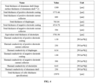
FIG. 3 is a comparison chart of results of kinetic parameter fitting data according to an embodiment of the present disclosure; and -
FIG. 4 is a comparison chart of thermal conductivity data of each component in the battery according to an embodiment of the present disclosure. - It should be noted that embodiments in the present disclosure and features in the embodiments can be combined with each other without conflicts.
- The present disclosure will be described in detail below with reference to the accompanying drawings and in conjunction with the embodiments.
- This embodiment relates to a battery thermal runaway prediction method. The method includes: when a hot box temperature T, a battery self-heating starting temperature T1 and a thermal runaway starting temperature T2 satisfy T1 < T < T2: if a battery self-heating rate K1 is greater than a rate K2 of heat transfer from a hot box to an interior of a battery, thermal runaway occurring at a surface of the battery first. If the battery self-heating rate K1 is less than the rate K2 of heat transfer from the hot box to the interior of the battery, thermal runaway occurs first when self-produced heat inside the battery accumulates to a limit value, and thermal runaway does not occur when the self-produced heat inside the battery has not accumulated to the limit value.
- It should be noted that the above hot box temperature is a temperature simulating a working environment of the battery. The battery self-heating starting temperature T1 is determined by the battery self-heating rate ≥ 0.02 °C/min. The thermal runaway starting temperature T2 is determined by the battery self-heating rate > 1 °C/min.
- In specific implementation, the battery self-heating rate in this embodiment is

- It should be noted here that the peak sorting refers to distinguishing the amount of peaks in the DSC test curve, and then sorting all peaks from 1, which can be called the first peak, the second peak, and the y-th peak, x = 1, 2...y. Parameters such as Ax, Ea, x, Tx and αx correspond to values of the peaks, and the parameters will change accordingly if the values of the peaks are different, which can be determined in a process of fitting the DSC test curve.
- Besides, the battery self-heating rate K1 is obtained by respectively carrying out a DSC (Differential Scanning Calorimetry) test according to positive electrode and negative electrode, positive electrode and electrolyte, and negative electrode and electrolyte, then carrying out kinetic parameter fitting, respectively calculating self-heating rates of the three, and then summing the self-heating rates of the three.
- The reaction mechanism function is f(αx)=(1-αx)n(1+Kcatαx), where: n is a reaction order, Kcat is a catalytic coefficient, and αx is a proportion of reactants participating in an autocatalytic reaction. Apparently, the reaction mechanism function f(αx)=(1-αx)n(1 +Kcatαx) is not fixed, and batteries of different systems further correspond to different reaction mechanism functions in the case of fitting.
- In specific implementation, in this embodiment, the rate of heat transfer from the hot box to the interior of the battery is

- In this embodiment, when the hot box temperature T and the battery self-heating starting temperature T1 satisfy T < T1, battery thermal runaway does not occur. Besides, when the hot box temperature T and the thermal runaway starting temperature T2 satisfy T > T2, thermal runaway occurs at a surface of the battery first.
- The method of the present disclosure is further described below based on a specific test to verify feasibility of the method of the present disclosure. Firstly, each component of the battery is subjected to a DSC test, three items with the maximum heat release are selected to test at different heating rates, data obtained from the test is fitted to obtain kinetic parameters, and then self-heating rates are calculated. The specific test process and test parameters are as follows:
- S1. Charge a battery to a full state of charge by 1/3C CC-CV (Constant Current/Constant Voltage), and then disassemble the battery in a glove box.
- S2. Soak and clean positive and negative electrode pieces obtained by disassembling with DMC (dimethyl carbonate) for three times and 5 min each time, and then air the positive and negative electrode pieces in the glove box, where, the positive electrode piece needs to be baked in vacuum at 60 °C, and then packaged into a aluminum-plastic film, while the negative electrode piece does not need additional conditions, and is aired at a room temperature in the glove box, and then packaged into the aluminum-plastic film.
It should be noted that DMC (dimethyl carbonate) is an organic compound with a chemical formula of C3H6O3. DMC has excellent solubility and low boiling point characteristics. In practical applications, in addition to using the DMC to soak and clean the positive and negative electrode pieces, other organic solvents with low boiling points can also be used, such as DEC (diethyl carbonate). - S3. Make a sample in the glove box, punch and cut a plurality of electrode pieces (including at least four positive electrode pieces and four negative electrode pieces) with a diameter of D (a value of D can be changed according to an actual design requirement, and the diameter of ϕ5 mm is selected for this test), and take out a plurality of steel crucibles;
- then, put the plurality of electrode pieces into the steel crucibles respectively, and put 2 µL of electrolyte into part of the steel crucibles to make test samples with components being positive electrode, negative electrode, electrolyte, positive electrode + electrolyte, negative electrode + electrolyte, positive electrode + negative electrode, and positive electrode + negative electrode + electrolyte.
- S4. Perform the DSC test on each test sample in step S3, and change a temperature of each test sample at a different heating rate during the test from 25 °C to 450 °C, where the heating rates are 5 °C/min, 10 °C/min, 15 °C/min, or 20 °C/min, respectively.
- Test results are shown in
FIGs. 1 to 4 , in whichFIG. 1 shows a DSC test curve of each component in the battery, a horizontal axis being a temperature, and a vertical axis being a heat release. Referring toFIG. 1 , when a temperature in the horizontal axis is 100 °C, test samples characterized by curves in the figure sequentially from bottom to top are positive electrode, negative electrode, electrolyte, positive electrode + electrolyte, negative electrode + electrolyte, positive electrode + negative electrode, and positive electrode + negative electrode + electrolyte.FIG. 2 is a comparison chart of DSC test results of heat production of each component in the battery, from which it can be seen that the test samples of positive electrode + electrolyte, negative electrode + electrolyte and positive electrode + negative electrode have the highest heat production. - Therefore, these three items are selected for kinetic parameter fitting, that is, the reaction mechanism function f(αx)=(1-αx)n(1+Kcatαx) is used for calculation to obtain the fitting results shown in
FIG. 3 . Now, the test result of positive electrode + electrolyte inFIG. 3 is selected to calculate the self-heating rate of the battery:Kpositive electrode + electrolyte = Kpositive electrode + electrolyte - 1 + Kpositive electrode + electrolyte - 2 = {3.639 × 10¹⁸ × e ̂[(-212962) / (8.314 × 491.47)] × (1 - 0.39)2.665 × (1 + 977.237 × 0.39)} + {1.14 × 10⁶ × e ̂[(-91470) / (8.314 × 530.413)] × (1 - 0.61)2.274 × (1 + 70.307 × 0.61)} = 14.4 - where, 3.639×10¹⁸ and 1.14×10⁶ are pre-exponential factors of the corresponding positive electrode + electrolyte test samples in
FIG. 3 ; - 212962 and 91470 are activation energies of reactions in
FIG. 3 for the positive electrode + electrolyte test samples; - 8.314 is a molar gas constant R; 491.47 and 530.413 are hot box temperatures T;
- (1-0.39)2.665×(1+977.237×0.39) and (1-0.61)2.274×(1+70.307×0.61) are reaction mechanism functions f(αx);
- 0.39 and 0.61 are αx, which are obtained by fitting kinetic parameters using NETZSCHKineticsNeo software (NETZSCH thermal kinetics software).
- In the same way, Knegative electrode + electrolyte = 11.26; and Kpositive electrode + negative electrode = 11.02.
- Therefore, the total self-heating rate of the battery is K1=14.4+11.26+11.02=36.68.
- At this time, the internal heat transfer rate of the battery is calculate by the heat transfer
rate formula 
FIG. 4 , and the thickness di of each component and the total thickness d of the electrode group in the battery tested by a conventional means. - As can be seen from comparison between the total battery self-heating rate K1 and the rate K2 of heat transfer in the battery, due to K1 < K2, thermal runaway occurs first when self-produced heat inside the battery accumulates to a limit value, and thermal runaway does not occur when the self-produced heat inside the battery has not accumulated to the limit value. Therefore, on the basis of the total battery self-heating rate K1 and the heat transfer rate K2 obtained by calculation, the safety of the battery can be characterized, and K1 can also be used to accurately characterize the safety boundary of the battery hot box test.
- To sum up, a way to characterize the safety of the battery and the safety boundary in this embodiment is specifically as follows:
- A. When T < T1, the battery can work safely without thermal runaway, and at this time, T1 is used to characterize the safety boundary at which the battery can work safely.
- B. When T > T2, the battery can not work, thermal runaway occurs at the surface thereof first, and at this time, T2 is used to characterize to exceed the safety operation boundary of the battery.
- C. When T1 < T < T2, K1 and K2 need to be calculated; if K1 > K2, thermal runaway occurs at the surface of the battery first, and at this time, T is used to characterize to exceed the safety operation boundary of the battery; and if K1 < K2, T/K1=h (working time), a working time of the battery at the temperature T can be calculated, and at this time, T and h are together used to characterize the safety operation boundary of the battery.
- The battery thermal runaway prediction method of this embodiment, by comparing the battery self-heating rate K1 and the rate K2 of heat transfer from the hot box to the interior of the battery and acquiring the limit value of the self-generated heat accumulated inside the battery, can replace the hot box test method to assess the safety of the battery and accurately acquire the safety boundary of the battery hot box test, and further realize characterization of the safety of the battery. Besides, the test cost and period can be saved, and the requirements of repeated tests can be met under the condition of a small amount of samples, and the method is quick, simple and effective.
- This embodiment further provides a battery thermal runaway prediction apparatus, including a battery thermal runaway prediction device and a computer. The computer includes a memory and a processor, a computer program is stored in the memory, and the computer program, when run on the processor, executes the battery thermal runaway prediction method in this embodiment.
- In addition, this embodiment further provides a computer-readable storage medium, in which a computer program is stored. The computer program, when run on the processor, executes the battery thermal runaway prediction method in this embodiment.
- Those skilled in the art may understand that implementation of all or part of the process of the method of the above embodiment is accomplished by the computer program or instruction-related hardware. The computer program may be stored in a computer-readable storage medium, and when executed, the program may include the process of the above embodiment of each above method. Any reference to a memory, a processor, a computer program, or other medium used in the embodiments presented herein may include a non-volatile and/or volatile memory.
- The non-volatile memory can include a read only memory (ROM), a programmable ROM (PROM), an electrically programmable ROM (EPROM), an electrically erasable programmable ROM (EEPROM), or a flash memory. The volatile memory may include a random access memory (RAM) or an external cache memory.
- Apparently, the RAM may be obtained in a variety of forms, such as a static RAM (SRAM), a dynamic RAM (DRAM), a double data rate SDRAM (DDRSDRAM), a memory bus (Rambus) direct RAM (RDRAM), a synchronous DRAM (SDRAM), a direct Rambus dynamic RAM (DRDRAM), and a Rambus dynamic RAM (RDRAM).
- The above description is only a preferred embodiment of the present disclosure, and is not intended to limit the present disclosure. Any modification, equivalent substitution, improvement, and the like within the spirit and principle of the present disclosure shall be included in the protection scope of the present disclosure.
Claims (15)
- A battery thermal runaway prediction method, comprising:
when a hot box temperature T, a battery self-heating starting temperature T1 and a thermal runaway starting temperature T2 satisfy T1 < T < T2:if a battery self-heating rate K1 is greater than a rate K2 of heat transfer from a hot box to an interior of a battery, thermal runaway occurring at a surface of the battery first; andif the battery self-heating rate K1 is less than the rate K2 of heat transfer from the hot box to the interior of the battery, thermal runaway occurring first when self-produced heat inside the battery accumulates to a limit value, and thermal runaway not occurring when the self-produced heat inside the battery has not accumulated to the limit value. - The battery thermal runaway prediction method of claim 1, wherein:the battery self-heating rate is
 wherein: Ax is a pre-exponential factor; Ea, x is activation energy of a reaction; R is a molar gas constant; Tx is a peak temperature; f(αx) is a reaction mechanism function; x is a lower limit value of a peak sorting of a DSC test curve, and y is an upper limit value of the peak sorting of the DSC test curve.
 - The battery thermal runaway prediction method of claim 2, wherein:the reaction mechanism function is f(αx)=(1-αx)n(1+Kcatαx),wherein: n is a reaction order, Kcat is a catalytic coefficient, and αx is a proportion of reactants participating in an autocatalytic reaction.
- The battery thermal runaway prediction method of claim 2, wherein:
the battery self-heating rate K1 is obtained by respectively carrying out a DSC test according to a positive electrode and a negative electrode, a positive electrode and an electrolyte, and a negative electrode and an electrolyte, then carrying out kinetic parameter fitting, respectively calculating self-heating rates of the three, and then summing the self-heating rates of the three. - The battery thermal runaway prediction method of claim 4, wherein:
the DSC test comprises steps:S1, charging a battery to a full state of charge by 1/3C CC-CV (Constant Current/Constant Voltage), and then disassembling the battery;S2, soaking and cleaning positive and negative electrode pieces obtained by disassembling, and then drying the positive and negative electrode pieces;S3, punching and cutting the positive and negative electrode pieces in step S2 to obtain a plurality of electrode pieces with a diameter of D, and then placing part of the electrode pieces in the electrolyte to make test samples with components being positive electrode, negative electrode, electrolyte, positive electrode + electrolyte, negative electrode + electrolyte, positive electrode + negative electrode, and positive electrode + negative electrode + electrolyte respectively; andS4, performing the DSC test on each test sample in step S3, and changing an ambient temperature of each test sample at a different heating rate during the test. - The battery thermal runaway prediction method of claim 5, wherein:
in step S2, DMC (dimethyl carbonate) is used as a solvent for soaking and cleaning, and/or, soaking and cleaning are carried out for 3 times, and/or, each soaking lasts for 5 minutes, and/or, the positive electrode piece obtained by disassembling is dried in a vacuum environment at 60 °C. - The battery thermal runaway prediction method of claim 5, wherein:
in step S3, the diameter D is ϕ5 mm, and/or, a number of the punched and cut positive and negative electrode pieces is more than or equal to 4. - The battery thermal runaway prediction method of claim 5, wherein:
in step S4, temperatures before and after the heating are 25 °C and 450 °C, respectively, and/or, the heating rates are 5 °C/min, 10 °C/min, 15 °C/min, or 20 °C/min, respectively. - The battery thermal runaway prediction method of claim 1, wherein:the rate of heat transfer from the hot box to the interior of the battery is
 wherein: ki is a thermal conductivity of each component of the battery; di is a thickness of each component of the battery; d is a total thickness of an inner electrode group of the battery; i is a lower limit value of a number of component types of the battery; and m is an upper limit value of a number of the component types of the battery.
 - The battery thermal runaway prediction method of claim 9, wherein:
the components of the battery comprises: a positive electrode coating, a positive electrode current collector, a diaphragm, a negative electrode coating, a negative electrode current collector, an electrolyte and an aluminum shell. - The battery thermal runaway prediction method of any one of claims 1-10, wherein:
when the hot box temperature T and the battery self-heating starting temperature T1 satisfy T < T1, battery thermal runaway does not occur. - The battery thermal runaway prediction method of any one of claims 1-10, wherein:
when the hot box temperature T and the thermal runaway starting temperature T2 satisfy T > T2, thermal runaway occurs at a surface of the battery first. - The battery thermal runaway prediction method of any one of claims 1-10, wherein:
the battery self-heating starting temperature T1 is determined by the battery self-heating rate ≥ 0.02 °C/min; and/or, the thermal runaway starting temperature T2 is determined by the battery self-heating rate > 1 °C/min. - A battery thermal runaway prediction apparatus, comprising a battery thermal runaway prediction device and a computer, wherein the computer comprises a memory and a processor, a computer program is stored in the memory, and the computer program, when run on the processor, executes the battery thermal runaway prediction method of any one of claims 1-13.
- A computer-readable storage medium, in which a computer program is stored, wherein the computer program, when run on a processor, executes the battery thermal runaway prediction method of any one of claims 1-13.
Applications Claiming Priority (2)
| Application Number | Priority Date | Filing Date | Title |
|---|---|---|---|
| CN202111058590.XA CN113505500B (en) | 2021-09-10 | 2021-09-10 | Battery thermal runaway prediction method, device and computer readable storage medium |
| PCT/CN2022/094746 WO2023035672A1 (en) | 2021-09-10 | 2022-05-24 | Battery thermal runaway prediction method and apparatus, and computer-readable storage medium |
Publications (2)
| Publication Number | Publication Date |
|---|---|
| EP4394641A1 true EP4394641A1 (en) | 2024-07-03 |
| EP4394641A4 EP4394641A4 (en) | 2025-03-12 |
Family
ID=78017065
Family Applications (1)
| Application Number | Title | Priority Date | Filing Date |
|---|---|---|---|
| EP22866150.0A Pending EP4394641A4 (en) | 2021-09-10 | 2022-05-24 | Battery thermal runaway prediction method and apparatus, and computer-readable storage medium |
Country Status (4)
| Country | Link |
|---|---|
| US (1) | US20240377457A1 (en) |
| EP (1) | EP4394641A4 (en) |
| CN (1) | CN113505500B (en) |
| WO (1) | WO2023035672A1 (en) |
Families Citing this family (6)
| Publication number | Priority date | Publication date | Assignee | Title |
|---|---|---|---|---|
| EP4320675A2 (en) | 2021-07-02 | 2024-02-14 | Aspen Aerogels, Inc. | Systems and methods for mitigating thermal propagation in battery-based energy storage systems |
| CN113505500B (en) * | 2021-09-10 | 2021-12-10 | 蜂巢能源科技有限公司 | Battery thermal runaway prediction method, device and computer readable storage medium |
| CN114325423A (en) * | 2021-12-30 | 2022-04-12 | 北京胜能能源科技有限公司 | A test method for thermal runaway temperature of lithium-ion batteries |
| CN116049640B (en) * | 2023-04-03 | 2023-07-07 | 河北工业大学 | A Probabilistic Mapping Recognition Method for Thermal Behavior Discrimination of Liquid-Liquid Heterogeneous Reactions |
| CN116859269B (en) * | 2023-09-04 | 2023-11-28 | 中国汽车技术研究中心有限公司 | Comprehensive evaluation method and system for safety of power battery |
| KR102950344B1 (en) * | 2024-11-21 | 2026-04-08 | 한양대학교 산학협력단 | Method and apparatus for predicting battery thermal runaway using artificial intelligence |
Family Cites Families (17)
| Publication number | Priority date | Publication date | Assignee | Title |
|---|---|---|---|---|
| US7736799B1 (en) * | 2009-07-17 | 2010-06-15 | Tesla Motors, Inc. | Method and apparatus for maintaining cell wall integrity during thermal runaway using an outer layer of intumescent material |
| FR2974922B1 (en) * | 2011-05-04 | 2013-04-26 | IFP Energies Nouvelles | OPTIMIZED METHOD FOR THE THERMAL MANAGEMENT OF AN ELECTROCHEMICAL STORAGE SYSTEM |
| CN105589046A (en) * | 2016-01-29 | 2016-05-18 | 金龙联合汽车工业(苏州)有限公司 | Detection and alarm method of power battery pack thermal runaway diffusion |
| CN106597299B (en) * | 2016-11-22 | 2019-01-25 | 南京能启能电子科技有限公司 | A kind of lithium battery thermal runaway early warning and autocontrol method |
| KR102589287B1 (en) * | 2017-01-19 | 2023-10-13 | 내션얼 리서치 카운슬 오브 캐나다 | Apparatus and method for initiating thermal runaway in a battery |
| CN108445039B (en) * | 2018-02-07 | 2021-05-04 | 清华大学 | Power battery thermal runaway safety performance prediction method and device and computer readable storage medium |
| CN108446434B (en) * | 2018-02-07 | 2020-02-11 | 清华大学 | Prediction method and device for thermal runaway safety of power battery and computer readable storage medium |
| CN109884527B (en) * | 2019-02-13 | 2025-08-19 | 深圳市比克动力电池有限公司 | Calculation method for thermal runaway heat generation amount of lithium ion battery |
| JP2022529607A (en) * | 2019-04-16 | 2022-06-23 | ザ ガバメント オブ ザ ユナイテッド ステイツ オブ アメリカ,アズ リプレゼンテッド バイ ザ セクレタリー オブ ザ ネイビー | Two-phase heat generation quenching |
| CN110957545B (en) * | 2019-12-16 | 2021-05-28 | 国联汽车动力电池研究院有限责任公司 | A detection method for thermal runaway diffusion inside a battery |
| CN111199106B (en) * | 2020-01-06 | 2022-10-21 | 上海空间电源研究所 | Method for acquiring parameters of battery thermal insulation thermal runaway process |
| CN111475933A (en) * | 2020-03-27 | 2020-07-31 | 中国电子科技集团公司第十八研究所 | A lithium-ion battery thermal runaway simulation method and system |
| CN111736075A (en) * | 2020-07-10 | 2020-10-02 | 中国民用航空飞行学院 | A method for thermal safety monitoring of lithium-ion batteries under dynamic pressure and temperature conditions |
| CN112630670B (en) * | 2020-12-16 | 2023-07-07 | 蜂巢能源科技股份有限公司 | Battery safety parameter acquisition method and device, storage medium and electronic equipment |
| CN112798049B (en) * | 2021-01-28 | 2023-03-14 | 国网江苏省电力有限公司经济技术研究院 | A thermal runaway gas production rate and gas production measurement device and method for a lithium-ion battery |
| CN112904204B (en) * | 2021-01-29 | 2023-06-02 | 天津市捷威动力工业有限公司 | A lithium battery safety risk assessment pre-judgment method |
| CN113505500B (en) * | 2021-09-10 | 2021-12-10 | 蜂巢能源科技有限公司 | Battery thermal runaway prediction method, device and computer readable storage medium |
-
2021
- 2021-09-10 CN CN202111058590.XA patent/CN113505500B/en active Active
-
2022
- 2022-05-24 WO PCT/CN2022/094746 patent/WO2023035672A1/en not_active Ceased
- 2022-05-24 US US18/691,012 patent/US20240377457A1/en active Pending
- 2022-05-24 EP EP22866150.0A patent/EP4394641A4/en active Pending
Also Published As
| Publication number | Publication date |
|---|---|
| CN113505500B (en) | 2021-12-10 |
| CN113505500A (en) | 2021-10-15 |
| US20240377457A1 (en) | 2024-11-14 |
| EP4394641A4 (en) | 2025-03-12 |
| WO2023035672A1 (en) | 2023-03-16 |
Similar Documents
| Publication | Publication Date | Title |
|---|---|---|
| EP4394641A1 (en) | Battery thermal runaway prediction method and apparatus, and computer-readable storage medium | |
| Abada et al. | Combined experimental and modeling approaches of the thermal runaway of fresh and aged lithium-ion batteries | |
| Peng et al. | Thermal safety of lithium-ion batteries with various cathode materials: A numerical study | |
| CN110095722B (en) | Comprehensive evaluation method and system for thermal runaway safety of power battery | |
| Zavalis et al. | Investigation of short-circuit scenarios in a lithium-ion battery cell | |
| US20200371054A1 (en) | Method and Apparatus for Predicting Thermal Runaway Safety of Power Battery and Computer Readable Storage Medium | |
| Cai et al. | Modeling li-ion battery temperature and expansion force during the early stages of thermal runaway triggered by internal shorts | |
| Zhao et al. | Simulation and experimental study on lithium ion battery short circuit | |
| Lin et al. | Thermal runaway and gas production characteristics of semi-solid electrolyte and liquid electrolyte lithium-Ion batteries: A comparative study | |
| CN110109020B (en) | Database-driven power battery thermal runaway safety forward evaluation method and device | |
| Karmakar et al. | State-of-charge implications of thermal runaway in Li-ion cells and modules | |
| Zhao et al. | Numerical modeling of thermal runaway for low temperature cycling lithium-ion batteries | |
| CN112782599A (en) | Nondestructive lithium analysis detection method and device for lithium ion battery and computer equipment | |
| Wang et al. | Thermal explosion energy evaluated by thermokinetic analysis for series-and parallel-circuit NMC lithium battery modules | |
| Duh et al. | Thermal runaway on 18650 lithium-ion batteries containing cathode materials with and without the coating of self-terminated oligomers with hyper-branched architecture (STOBA) used in electric vehicles | |
| CN108446435B (en) | Power battery electrode material thermal stability judgment method and device and computer readable storage medium | |
| Jones et al. | Direct measurement of internal temperatures of commercially-available 18650 lithium-ion batteries | |
| Burns et al. | Impedance reducing additives and their effect on cell performance: II. C3H9B3O6 | |
| CN109459463A (en) | A kind of quick evaluation method of anode material for lithium-ion batteries hot storage stability | |
| Guo et al. | Thermal runaway behaviors and kinetics of NCM lithium-ion batteries at different heat dissipation conditions | |
| Wang et al. | Analysis of early-stage behavior and multi-parameter early warning algorithm research for overcharge thermal runaway of energy storage LiFePO4 battery packs | |
| Shukla et al. | Size‐dependent failure behavior of commercially available lithium‐iron phosphate battery under mechanical abuse | |
| Li et al. | Electrochemical-thermal behaviors of retired power lithium-ion batteries during high-temperature and overcharge/over-discharge cycles | |
| Pal et al. | A comprehensive review of thermal runaway for batteries: experimental; modelling, challenges and proposed framework | |
| CN118584379B (en) | Battery thermophysical parameter determination method, related device and storage medium |
Legal Events
| Date | Code | Title | Description |
|---|---|---|---|
| STAA | Information on the status of an ep patent application or granted ep patent |
Free format text: STATUS: THE INTERNATIONAL PUBLICATION HAS BEEN MADE |
|
| PUAI | Public reference made under article 153(3) epc to a published international application that has entered the european phase |
Free format text: ORIGINAL CODE: 0009012 |
|
| STAA | Information on the status of an ep patent application or granted ep patent |
Free format text: STATUS: REQUEST FOR EXAMINATION WAS MADE |
|
| 17P | Request for examination filed |
Effective date: 20240325 |
|
| AK | Designated contracting states |
Kind code of ref document: A1 Designated state(s): AL AT BE BG CH CY CZ DE DK EE ES FI FR GB GR HR HU IE IS IT LI LT LU LV MC MK MT NL NO PL PT RO RS SE SI SK SM TR |
|
| DAV | Request for validation of the european patent (deleted) | ||
| DAX | Request for extension of the european patent (deleted) | ||
| A4 | Supplementary search report drawn up and despatched |
Effective date: 20250211 |
|
| RIC1 | Information provided on ipc code assigned before grant |
Ipc: H01M 10/633 20140101ALI20250205BHEP Ipc: H01M 10/613 20140101ALI20250205BHEP Ipc: H01M 10/48 20060101ALI20250205BHEP Ipc: G06F 119/08 20200101ALI20250205BHEP Ipc: G06F 119/02 20200101ALI20250205BHEP Ipc: H01M 10/42 20060101ALI20250205BHEP Ipc: G06F 30/20 20200101AFI20250205BHEP |