EP4394564A1 - Input display device - Google Patents
Input display device Download PDFInfo
- Publication number
- EP4394564A1 EP4394564A1 EP23216276.8A EP23216276A EP4394564A1 EP 4394564 A1 EP4394564 A1 EP 4394564A1 EP 23216276 A EP23216276 A EP 23216276A EP 4394564 A1 EP4394564 A1 EP 4394564A1
- Authority
- EP
- European Patent Office
- Prior art keywords
- finger
- rotation
- knob
- unit
- fingers
- Prior art date
- Legal status (The legal status is an assumption and is not a legal conclusion. Google has not performed a legal analysis and makes no representation as to the accuracy of the status listed.)
- Granted
Links
Images




Classifications
-
- G—PHYSICS
- G06—COMPUTING OR CALCULATING; COUNTING
- G06F—ELECTRIC DIGITAL DATA PROCESSING
- G06F3/00—Input arrangements for transferring data to be processed into a form capable of being handled by the computer; Output arrangements for transferring data from processing unit to output unit, e.g. interface arrangements
- G06F3/01—Input arrangements or combined input and output arrangements for interaction between user and computer
- G06F3/03—Arrangements for converting the position or the displacement of a member into a coded form
- G06F3/041—Digitisers, e.g. for touch screens or touch pads, characterised by the transducing means
- G06F3/0416—Control or interface arrangements specially adapted for digitisers
-
- B—PERFORMING OPERATIONS; TRANSPORTING
- B60—VEHICLES IN GENERAL
- B60K—ARRANGEMENT OR MOUNTING OF PROPULSION UNITS OR OF TRANSMISSIONS IN VEHICLES; ARRANGEMENT OR MOUNTING OF PLURAL DIVERSE PRIME-MOVERS IN VEHICLES; AUXILIARY DRIVES FOR VEHICLES; INSTRUMENTATION OR DASHBOARDS FOR VEHICLES; ARRANGEMENTS IN CONNECTION WITH COOLING, AIR INTAKE, GAS EXHAUST OR FUEL SUPPLY OF PROPULSION UNITS IN VEHICLES
- B60K35/00—Instruments specially adapted for vehicles; Arrangement of instruments in or on vehicles
-
- B—PERFORMING OPERATIONS; TRANSPORTING
- B60—VEHICLES IN GENERAL
- B60K—ARRANGEMENT OR MOUNTING OF PROPULSION UNITS OR OF TRANSMISSIONS IN VEHICLES; ARRANGEMENT OR MOUNTING OF PLURAL DIVERSE PRIME-MOVERS IN VEHICLES; AUXILIARY DRIVES FOR VEHICLES; INSTRUMENTATION OR DASHBOARDS FOR VEHICLES; ARRANGEMENTS IN CONNECTION WITH COOLING, AIR INTAKE, GAS EXHAUST OR FUEL SUPPLY OF PROPULSION UNITS IN VEHICLES
- B60K35/00—Instruments specially adapted for vehicles; Arrangement of instruments in or on vehicles
- B60K35/10—Input arrangements, i.e. from user to vehicle, associated with vehicle functions or specially adapted therefor
-
- G—PHYSICS
- G06—COMPUTING OR CALCULATING; COUNTING
- G06F—ELECTRIC DIGITAL DATA PROCESSING
- G06F3/00—Input arrangements for transferring data to be processed into a form capable of being handled by the computer; Output arrangements for transferring data from processing unit to output unit, e.g. interface arrangements
- G06F3/01—Input arrangements or combined input and output arrangements for interaction between user and computer
- G06F3/03—Arrangements for converting the position or the displacement of a member into a coded form
- G06F3/033—Pointing devices displaced or positioned by the user, e.g. mice, trackballs, pens or joysticks; Accessories therefor
- G06F3/0354—Pointing devices displaced or positioned by the user, e.g. mice, trackballs, pens or joysticks; Accessories therefor with detection of two-dimensional [2D] relative movements between the device, or an operating part thereof, and a plane or surface, e.g. 2D mice, trackballs, pens or pucks
- G06F3/03547—Touch pads, in which fingers can move on a surface
-
- G—PHYSICS
- G06—COMPUTING OR CALCULATING; COUNTING
- G06F—ELECTRIC DIGITAL DATA PROCESSING
- G06F3/00—Input arrangements for transferring data to be processed into a form capable of being handled by the computer; Output arrangements for transferring data from processing unit to output unit, e.g. interface arrangements
- G06F3/01—Input arrangements or combined input and output arrangements for interaction between user and computer
- G06F3/03—Arrangements for converting the position or the displacement of a member into a coded form
- G06F3/033—Pointing devices displaced or positioned by the user, e.g. mice, trackballs, pens or joysticks; Accessories therefor
- G06F3/0362—Pointing devices displaced or positioned by the user, e.g. mice, trackballs, pens or joysticks; Accessories therefor with detection of one-dimensional [1D] translations or rotations of an operating part of the device, e.g. scroll wheels, sliders, knobs, rollers or belts
-
- G—PHYSICS
- G06—COMPUTING OR CALCULATING; COUNTING
- G06F—ELECTRIC DIGITAL DATA PROCESSING
- G06F3/00—Input arrangements for transferring data to be processed into a form capable of being handled by the computer; Output arrangements for transferring data from processing unit to output unit, e.g. interface arrangements
- G06F3/01—Input arrangements or combined input and output arrangements for interaction between user and computer
- G06F3/03—Arrangements for converting the position or the displacement of a member into a coded form
- G06F3/033—Pointing devices displaced or positioned by the user, e.g. mice, trackballs, pens or joysticks; Accessories therefor
- G06F3/039—Accessories therefor, e.g. mouse pads
- G06F3/0393—Accessories for touch pads or touch screens, e.g. mechanical guides added to touch screens for drawing straight lines, hard keys overlaying touch screens or touch pads
-
- G—PHYSICS
- G06—COMPUTING OR CALCULATING; COUNTING
- G06F—ELECTRIC DIGITAL DATA PROCESSING
- G06F3/00—Input arrangements for transferring data to be processed into a form capable of being handled by the computer; Output arrangements for transferring data from processing unit to output unit, e.g. interface arrangements
- G06F3/01—Input arrangements or combined input and output arrangements for interaction between user and computer
- G06F3/03—Arrangements for converting the position or the displacement of a member into a coded form
- G06F3/041—Digitisers, e.g. for touch screens or touch pads, characterised by the transducing means
- G06F3/0416—Control or interface arrangements specially adapted for digitisers
- G06F3/0418—Control or interface arrangements specially adapted for digitisers for error correction or compensation, e.g. based on parallax, calibration or alignment
- G06F3/04186—Touch location disambiguation
-
- G—PHYSICS
- G06—COMPUTING OR CALCULATING; COUNTING
- G06F—ELECTRIC DIGITAL DATA PROCESSING
- G06F3/00—Input arrangements for transferring data to be processed into a form capable of being handled by the computer; Output arrangements for transferring data from processing unit to output unit, e.g. interface arrangements
- G06F3/01—Input arrangements or combined input and output arrangements for interaction between user and computer
- G06F3/03—Arrangements for converting the position or the displacement of a member into a coded form
- G06F3/041—Digitisers, e.g. for touch screens or touch pads, characterised by the transducing means
- G06F3/044—Digitisers, e.g. for touch screens or touch pads, characterised by the transducing means by capacitive means
-
- G—PHYSICS
- G06—COMPUTING OR CALCULATING; COUNTING
- G06F—ELECTRIC DIGITAL DATA PROCESSING
- G06F3/00—Input arrangements for transferring data to be processed into a form capable of being handled by the computer; Output arrangements for transferring data from processing unit to output unit, e.g. interface arrangements
- G06F3/01—Input arrangements or combined input and output arrangements for interaction between user and computer
- G06F3/048—Interaction techniques based on graphical user interfaces [GUI]
- G06F3/0481—Interaction techniques based on graphical user interfaces [GUI] based on specific properties of the displayed interaction object or a metaphor-based environment, e.g. interaction with desktop elements like windows or icons, or assisted by a cursor's changing behaviour or appearance
- G06F3/04817—Interaction techniques based on graphical user interfaces [GUI] based on specific properties of the displayed interaction object or a metaphor-based environment, e.g. interaction with desktop elements like windows or icons, or assisted by a cursor's changing behaviour or appearance using icons
-
- G—PHYSICS
- G06—COMPUTING OR CALCULATING; COUNTING
- G06F—ELECTRIC DIGITAL DATA PROCESSING
- G06F3/00—Input arrangements for transferring data to be processed into a form capable of being handled by the computer; Output arrangements for transferring data from processing unit to output unit, e.g. interface arrangements
- G06F3/01—Input arrangements or combined input and output arrangements for interaction between user and computer
- G06F3/048—Interaction techniques based on graphical user interfaces [GUI]
- G06F3/0484—Interaction techniques based on graphical user interfaces [GUI] for the control of specific functions or operations, e.g. selecting or manipulating an object, an image or a displayed text element, setting a parameter value or selecting a range
- G06F3/04847—Interaction techniques to control parameter settings, e.g. interaction with sliders or dials
-
- G—PHYSICS
- G06—COMPUTING OR CALCULATING; COUNTING
- G06F—ELECTRIC DIGITAL DATA PROCESSING
- G06F3/00—Input arrangements for transferring data to be processed into a form capable of being handled by the computer; Output arrangements for transferring data from processing unit to output unit, e.g. interface arrangements
- G06F3/01—Input arrangements or combined input and output arrangements for interaction between user and computer
- G06F3/048—Interaction techniques based on graphical user interfaces [GUI]
- G06F3/0487—Interaction techniques based on graphical user interfaces [GUI] using specific features provided by the input device, e.g. functions controlled by the rotation of a mouse with dual sensing arrangements, or of the nature of the input device, e.g. tap gestures based on pressure sensed by a digitiser
- G06F3/0488—Interaction techniques based on graphical user interfaces [GUI] using specific features provided by the input device, e.g. functions controlled by the rotation of a mouse with dual sensing arrangements, or of the nature of the input device, e.g. tap gestures based on pressure sensed by a digitiser using a touch-screen or digitiser, e.g. input of commands through traced gestures
- G06F3/04883—Interaction techniques based on graphical user interfaces [GUI] using specific features provided by the input device, e.g. functions controlled by the rotation of a mouse with dual sensing arrangements, or of the nature of the input device, e.g. tap gestures based on pressure sensed by a digitiser using a touch-screen or digitiser, e.g. input of commands through traced gestures for inputting data by handwriting, e.g. gesture or text
-
- B—PERFORMING OPERATIONS; TRANSPORTING
- B60—VEHICLES IN GENERAL
- B60K—ARRANGEMENT OR MOUNTING OF PROPULSION UNITS OR OF TRANSMISSIONS IN VEHICLES; ARRANGEMENT OR MOUNTING OF PLURAL DIVERSE PRIME-MOVERS IN VEHICLES; AUXILIARY DRIVES FOR VEHICLES; INSTRUMENTATION OR DASHBOARDS FOR VEHICLES; ARRANGEMENTS IN CONNECTION WITH COOLING, AIR INTAKE, GAS EXHAUST OR FUEL SUPPLY OF PROPULSION UNITS IN VEHICLES
- B60K2360/00—Indexing scheme associated with groups B60K35/00 or B60K37/00 relating to details of instruments or dashboards
- B60K2360/11—Instrument graphical user interfaces or menu aspects
- B60K2360/119—Icons
-
- B—PERFORMING OPERATIONS; TRANSPORTING
- B60—VEHICLES IN GENERAL
- B60K—ARRANGEMENT OR MOUNTING OF PROPULSION UNITS OR OF TRANSMISSIONS IN VEHICLES; ARRANGEMENT OR MOUNTING OF PLURAL DIVERSE PRIME-MOVERS IN VEHICLES; AUXILIARY DRIVES FOR VEHICLES; INSTRUMENTATION OR DASHBOARDS FOR VEHICLES; ARRANGEMENTS IN CONNECTION WITH COOLING, AIR INTAKE, GAS EXHAUST OR FUEL SUPPLY OF PROPULSION UNITS IN VEHICLES
- B60K2360/00—Indexing scheme associated with groups B60K35/00 or B60K37/00 relating to details of instruments or dashboards
- B60K2360/126—Rotatable input devices for instruments
-
- B—PERFORMING OPERATIONS; TRANSPORTING
- B60—VEHICLES IN GENERAL
- B60K—ARRANGEMENT OR MOUNTING OF PROPULSION UNITS OR OF TRANSMISSIONS IN VEHICLES; ARRANGEMENT OR MOUNTING OF PLURAL DIVERSE PRIME-MOVERS IN VEHICLES; AUXILIARY DRIVES FOR VEHICLES; INSTRUMENTATION OR DASHBOARDS FOR VEHICLES; ARRANGEMENTS IN CONNECTION WITH COOLING, AIR INTAKE, GAS EXHAUST OR FUEL SUPPLY OF PROPULSION UNITS IN VEHICLES
- B60K2360/00—Indexing scheme associated with groups B60K35/00 or B60K37/00 relating to details of instruments or dashboards
- B60K2360/143—Touch sensitive instrument input devices
- B60K2360/1434—Touch panels
-
- B—PERFORMING OPERATIONS; TRANSPORTING
- B60—VEHICLES IN GENERAL
- B60K—ARRANGEMENT OR MOUNTING OF PROPULSION UNITS OR OF TRANSMISSIONS IN VEHICLES; ARRANGEMENT OR MOUNTING OF PLURAL DIVERSE PRIME-MOVERS IN VEHICLES; AUXILIARY DRIVES FOR VEHICLES; INSTRUMENTATION OR DASHBOARDS FOR VEHICLES; ARRANGEMENTS IN CONNECTION WITH COOLING, AIR INTAKE, GAS EXHAUST OR FUEL SUPPLY OF PROPULSION UNITS IN VEHICLES
- B60K2360/00—Indexing scheme associated with groups B60K35/00 or B60K37/00 relating to details of instruments or dashboards
- B60K2360/16—Type of output information
- B60K2360/168—Target or limit values
-
- B—PERFORMING OPERATIONS; TRANSPORTING
- B60—VEHICLES IN GENERAL
- B60K—ARRANGEMENT OR MOUNTING OF PROPULSION UNITS OR OF TRANSMISSIONS IN VEHICLES; ARRANGEMENT OR MOUNTING OF PLURAL DIVERSE PRIME-MOVERS IN VEHICLES; AUXILIARY DRIVES FOR VEHICLES; INSTRUMENTATION OR DASHBOARDS FOR VEHICLES; ARRANGEMENTS IN CONNECTION WITH COOLING, AIR INTAKE, GAS EXHAUST OR FUEL SUPPLY OF PROPULSION UNITS IN VEHICLES
- B60K35/00—Instruments specially adapted for vehicles; Arrangement of instruments in or on vehicles
- B60K35/20—Output arrangements, i.e. from vehicle to user, associated with vehicle functions or specially adapted therefor
- B60K35/28—Output arrangements, i.e. from vehicle to user, associated with vehicle functions or specially adapted therefor characterised by the type of the output information, e.g. video entertainment or vehicle dynamics information; characterised by the purpose of the output information, e.g. for attracting the attention of the driver
-
- G—PHYSICS
- G06—COMPUTING OR CALCULATING; COUNTING
- G06F—ELECTRIC DIGITAL DATA PROCESSING
- G06F2203/00—Indexing scheme relating to G06F3/00 - G06F3/048
- G06F2203/041—Indexing scheme relating to G06F3/041 - G06F3/045
- G06F2203/04101—2.5D-digitiser, i.e. digitiser detecting the X/Y position of the input means, finger or stylus, also when it does not touch, but is proximate to the digitiser's interaction surface and also measures the distance of the input means within a short range in the Z direction, possibly with a separate measurement setup
-
- G—PHYSICS
- G06—COMPUTING OR CALCULATING; COUNTING
- G06F—ELECTRIC DIGITAL DATA PROCESSING
- G06F2203/00—Indexing scheme relating to G06F3/00 - G06F3/048
- G06F2203/041—Indexing scheme relating to G06F3/041 - G06F3/045
- G06F2203/04104—Multi-touch detection in digitiser, i.e. details about the simultaneous detection of a plurality of touching locations, e.g. multiple fingers or pen and finger
-
- G—PHYSICS
- G06—COMPUTING OR CALCULATING; COUNTING
- G06F—ELECTRIC DIGITAL DATA PROCESSING
- G06F2203/00—Indexing scheme relating to G06F3/00 - G06F3/048
- G06F2203/041—Indexing scheme relating to G06F3/041 - G06F3/045
- G06F2203/04108—Touchless 2D- digitiser, i.e. digitiser detecting the X/Y position of the input means, finger or stylus, also when it does not touch, but is proximate to the digitiser's interaction surface without distance measurement in the Z direction
Definitions
- the present invention relates to an input display device having a human-machine interface function, and more particularly to an input display device including a three-dimensional operation unit.
- An input display device in which a protrusion is provided on a touch panel disposed to be superimposed on a display, and an image such as an operation icon is displayed at a position overlapping the protrusion (for example, JP 2020-190832 A ). The user performs an input by performing a touch operation on the protrusion.
- a user interface (hereinafter, referred to as a three-dimensional UI) has been proposed in which a cover glass has an uneven shape to allow a touch position to be tactilely recognized and the touch position can be understood without gazing.
- Fig. 1A is an operation example of a conventional flat touch panel, and a user U visually recognizes an operation icon 12 displayed on a display 10 and performs an input by performing a touch operation on the position of the operation icon 12 (note in the example of Figure).
- Fig. 1B is an operation example of a touch panel having a three-dimensional UI
- Fig. 1C is a schematic cross-sectional view of the three-dimensional UI.
- a transparent cover lens 26 having an uneven shape is attached onto a touch panel 24, and a display 20 displays an operation icon 22 at a position overlapping the cover lens 26.
- the user U performs input by touching the cover lens 26 with a finger.
- a highly sensitive electrostatic sensor capable of sensing the electrostatic capacitance (distance) of the finger even when the finger is away from the sensor is used for the touch sensing, and the presence or absence of the touch can be determined even from on the thick cover lens 26. This makes it possible to reduce touch mistakes (operation error) under a situation where it is difficult to gaze at the in-vehicle display during driving.
- a cylindrical knob (button).
- the rotation operation is performed by sliding a side face of the knob with a finger pad, and the knob does not actually rotate.
- an icon 40 indicating a function (for example, volume or the like) assigned to the operation of a knob 30 is displayed at the lower part of the knob 30, and a gauge (scale) 50 indicating the rotation amount of the rotation operation on the knob 30 is displayed around the knob 30.
- the number of fingers sensed by the operation method of the user is assumed to vary.
- sensing is performed as one finger, or when the finger approaches during the rotation operation, sensing of the finger disappears.
- the rotation operation on the operation unit is determined based on the sensing result of the rotation amounts of all the fingers touching the operation unit, so that the rotation operation of the operation unit can be stably determined even if the number of sensed fingers increases or decreases.
- An input display device of the present invention provides an interface between a person and a machine.
- the input display device of the present invention is not particularly limited, but is applied to, for example, an electronic device equipped with a display with a touch panel on which a three-dimensional UI unit is formed.
- the electronic device equipped with the display with a touch panel is, for example, an in-vehicle device having a navigation function, an audio visual function, a television function, and the like.
- the touch panel 120 further includes one or more three-dimensional UI units (operation units) 130 on the front face of the transparent panel.
- Fig. 6 illustrates an example in which four three-dimensional UI units 130 are attached at the lower part of the touch panel 120, but the number and size of the three-dimensional UI units 130 are not particularly limited.
- the three-dimensional UI unit 130 may be made of a transparent material (for example, acrylic, polycarbonate, glass, and the like) so that an icon displayed on the display 110 can be visually recognized.
- the bottom face of the three-dimensional UI unit 130 may be attached to the touch panel 120 using, for example, a double-sided adhesive or may be integrally molded with a cover glass attached to the front face of the touch panel 120.
- the three-dimensional UI unit 130 includes at least a cylindrical knob or button (see Fig. 2 and the like) on which the user can perform a rotation operation (hereinafter, the three-dimensional UI unit 130 may be referred to as a knob 130).
- the user When performing a rotation operation on the knob 130, the user performs an operation of holding the knob 130 with one or a plurality of fingers and sliding a side face of the knob 130 with finger pads.
- the coordinates of the finger touching the knob 130 are sensed, the rotation amount of the finger is sensed based on the sensed coordinates of the finger, and the presence or absence of the rotation operation on the knob is determined from the sensed rotation amount. Details of the determination of the rotation operation will be described later.
- the operation determination unit 160 determines the presence or absence of a touch operation on the touch panel 120 or a touch operation (for example, a rotation operation on the knob) on the three-dimensional UI unit 130 based on the sensing result of the touch sensing unit 150.
- the touch includes not only contact of the user's finger to the touch panel 120 or the three-dimensional UI unit 130 but also approach of the finger to the touch panel 120 or the three-dimensional UI unit 130.
- the display control unit 170 displays an image and a video on the display 110, and displays a GUI image related to the operation of the three-dimensional UI unit 130 in an area where the three-dimensional UI unit 130 exists. In addition, the display control unit 170 switches an image to be displayed on the display 110 to another image in response to the operation determination unit 160 determining that a touch operation has been performed.
- the conventional problem is solved by an algorithm that can stably continue the rotation sensing even when the number of fingers sensed at the time of the rotation operation on the knob increases or decreases.
- a method of sensing the rotation amount of the finger will be described.
- a 0° position serving as a reference is set with respect to the coordinates of the center point C of the knob 130, and an angle corresponding to a position when a finger touches the knob circumference can be calculated.
- the right side is set to 0°, and the angle is set to increase counterclockwise.
- the operation determination unit 160 determines that the knob 130 has rotated clockwise.
- the display of the gauge 50 increases by one step, as shown in Fig. 2 .
- the fingers U1, U2, and U3 that are continuously sensed count the rotation amount of +5° at the time when the sensing of the finger U4 disappears, but all the rotation amounts of the fingers U1, U2, and U3 are updated to the rotation amount of +10° of the finger U4 that has disappeared. Thereafter, when the rotation amount newly counted by the fingers U1 to U3 is added to the updated rotation amount of +10° and +5° is counted as the new rotation amount of the finger U3, for example, as illustrated in Fig. 9D , the total rotation amount of the finger U3 reaches +15°, and thus the operation determination unit 160 determines that the knob 130 has been rotated.
- the sensing of the finger U4 is added as illustrated in Fig. 9F while the rotation amounts of the fingers U1 and U2 are +5° and the rotation amount of the finger U3 is +10° as illustrated in Fig. 9E , the rotation amount +10° counted by the finger U3 having the largest rotation amount is allocated to the added finger U4.
- the fingers U1 and U2 may maintain the counted rotation amount +5° as it is, or the rotation amounts of the fingers U1 and U2 may also be updated to the rotation amount +10° of the finger U3.
- the operation determination unit 160 resets the count value of the rotation amounts of all the fingers to 0, returns to the above 1 with the finger position at that time as a reference point, and again senses the finger touched on the knob and its angle.
- the touch sensing unit 150 measures the electrostatic capacitance of the sensor of the touch panel 120 at a constant cycle, and senses the coordinates of the touch position of the finger from the measurement result.
- the operation determination unit 160 determines whether the touch sensing unit 150 continuously senses the coordinates of the finger in the knob sensing area (S3), and when it is determined that the coordinates of the finger are continuously sensed, the operation determination unit acquires the coordinates of the touch position of the finger from the touch sensing unit 150 again (S4).
- the operation determination unit 160 determines whether the number of sensed fingers in step S4 is smaller than the number stored in the variable in step S1 (S5), and when the number of sensed fingers is not smaller than the number stored in the variable, the operation determination unit determines whether the number of sensed fingers is increased (S6).
- the operation determination unit 160 determines whether there is a finger whose variable value of the rotation amount exceeds the threshold value (S9), and when there is a finger whose variable value exceeds the threshold value, it is determined that the rotation operation on the knob has been performed (S10). When it is determined that there is the presence of the rotation operation, the operation determination unit 160 resets the rotation amount variable of each finger to the initial value (0) (S11).
- step S5 the operation determination unit 160 determines whether a rotation amount counted in the variable of the finger that was sensed and disappeared is the largest among the rotation amounts of all the fingers (S12). In a case where the rotation amount is the largest, the operation determination unit overwrites the rotation amount count values of all the continuously sensed fingers with the count value of the finger that was sensed and disappeared (S13), and the processing returns to step S3.
Landscapes
- Engineering & Computer Science (AREA)
- General Engineering & Computer Science (AREA)
- Theoretical Computer Science (AREA)
- Human Computer Interaction (AREA)
- Physics & Mathematics (AREA)
- General Physics & Mathematics (AREA)
- Chemical & Material Sciences (AREA)
- Combustion & Propulsion (AREA)
- Transportation (AREA)
- Mechanical Engineering (AREA)
- Position Input By Displaying (AREA)
- User Interface Of Digital Computer (AREA)
Abstract
Description
- The present invention relates to an input display device having a human-machine interface function, and more particularly to an input display device including a three-dimensional operation unit.
- An input display device is disclosed in which a protrusion is provided on a touch panel disposed to be superimposed on a display, and an image such as an operation icon is displayed at a position overlapping the protrusion (for example,
JP 2020-190832 A - In a display device that performs an operation with a capacitive touch panel, a user interface (hereinafter, referred to as a three-dimensional UI) has been proposed in which a cover glass has an uneven shape to allow a touch position to be tactilely recognized and the touch position can be understood without gazing.
-
Fig. 1A is an operation example of a conventional flat touch panel, and a user U visually recognizes anoperation icon 12 displayed on adisplay 10 and performs an input by performing a touch operation on the position of the operation icon 12 (note in the example of Figure). -
Fig. 1B is an operation example of a touch panel having a three-dimensional UI, andFig. 1C is a schematic cross-sectional view of the three-dimensional UI. Atransparent cover lens 26 having an uneven shape is attached onto atouch panel 24, and adisplay 20 displays anoperation icon 22 at a position overlapping thecover lens 26. The user U performs input by touching thecover lens 26 with a finger. A highly sensitive electrostatic sensor capable of sensing the electrostatic capacitance (distance) of the finger even when the finger is away from the sensor is used for the touch sensing, and the presence or absence of the touch can be determined even from on thethick cover lens 26. This makes it possible to reduce touch mistakes (operation error) under a situation where it is difficult to gaze at the in-vehicle display during driving. - Among the three-dimensional UIs, there is a cylindrical knob (button). In the operation on the knob, the rotation operation is performed by sliding a side face of the knob with a finger pad, and the knob does not actually rotate. For example, as illustrated in
Fig. 2A , anicon 40 indicating a function (for example, volume or the like) assigned to the operation of aknob 30 is displayed at the lower part of theknob 30, and a gauge (scale) 50 indicating the rotation amount of the rotation operation on theknob 30 is displayed around theknob 30. - As in the knob of the mechanical switch, the user holds the
cylindrical knob 30 with the fingers U, and slides the finger pad on the side face of theknob 30 to rotate the fingers U as illustrated inFig. 2B . When referring to agauge 50 and further performing the rotation operation, the user returns the finger U to the original position as illustrated inFig. 2C and slides the finger pad again on the side face of theknob 30 to rotate the fingers U. - The touch panel senses circumferential movement of the fingers U touching the
knob 30 and determines a rotation operation on the knob.Fig. 3A illustrates movement of fingers when the right rotation operation is performed on theknob 30 with two fingers. The conventional sensing algorithm of the rotation operation determines the rotation operation from the circumferential movement of one finger on the knob. As illustrated inFig. 3B , when the finger U moves on the circumference by, for example, 45 degrees, it is determined that the rotation operation is performed on theknob 30, and the display of one scale of thegauge 50 is increased or decreased. - When the knob is operated, the number of fingers sensed by the operation method of the user is assumed to vary.
- Assuming operation with one hand, the number of fingers operating the knob is 1 to 5.
- The distance of the finger operating the knob from the sensor of the touch panel varies depending on the finger. For example, as illustrated in
Fig. 4 , the distance from the sensor is closest to the finger U1, slightly close to the finger U2, and away from the finger U3. There is a finger that is not sensed when the distance from the sensor increases, or sensing of the finger disappears when the finger moves away from the knob during the rotation operation. - The distance between adjacent fingers is not uniform.
- When the distance between the two fingers is too short, sensing is performed as one finger, or when the finger approaches during the rotation operation, sensing of the finger disappears.
- In such a situation, when sensing of the referred finger repeatedly disappears before the rotation amount (for example, 45 degrees) for determining the presence or absence of the rotation operation is reached, a situation may occur in which the determination of rotation is not smoothly made no matter how much the user turns the knob. For example, when four fingers U1 to U4 are sensed on the
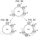
knob 30 as illustrated inFig. 5A , and then the finger U4 is away on the way as illustrated inFig. 5B , the number of sensed fingers is reduced to three, and in a case where the finger U4 is referred to, the determination of rotation of the knob cannot be made. As illustrated inFig. 5C , when the finger that is away approaches the knob, the number of sensed fingers increases to five. When the distance between the finger U4 and the finger U5 is too short, the finger U4 and the finger U5 are recognized as one finger, and when the finger U4 is referred to, the error of the sensed rotation amount increases, and the accuracy of the determination of rotation of the knob decreases. For this reason, in order to stably determine the rotation operation, a sensing algorithm considering movements of a plurality of fingers and an increase or decrease in the number of fingers to be sensed is required. - An object of the present invention is to provide an input display device capable of improving determination accuracy of a rotation operation on a three-dimensional operation unit.
- The invention relates to an input display device according to the appended claims. Embodiments are disclosed in the dependent claims.
- An input display device according to an aspect of the present invention includes a display configured to display an image, and a capacitive touch panel attached to the display and including at least one three-dimensional operation unit on a front face of the touch panel, and a sensing unit configured to measure an electrostatic capacitance of the touch panel and senses an operation on the touch panel based on the measured electrostatic capacitance, wherein the sensing unit senses rotation amounts of all fingers touching the operation unit, and determines that a rotation operation on the operation unit is performed when a sensed rotation amount of any of the fingers reaches a threshold value.
- In an embodiment, in a case where sensing of a finger disappears before a rotation amount of the finger having a largest rotation amount reaches the threshold value, the sensing unit updates rotation amounts of remaining fingers to a rotation amount of the finger having the largest rotation amount. In an embodiment, in a case where sensing of a finger touching the operation unit is added in a middle, the sensing unit allocates a rotation amount of a finger having a largest rotation amount to a rotation amount of an added finger. In an embodiment, the sensing unit resets a sensed rotation amount of a finger when determining that a rotation operation on the operation unit is performed. In an embodiment, the input display device in further includes a display unit configured to display a gauge, corresponding to a rotation operation, around the operation unit of the display. In an embodiment, the display unit displays an icon representing an input operation at a corresponding position of the operation unit of the display. In an embodiment, the operation unit has a cylindrical knob shape, a cylindrical button shape, or a cylindrical finger grip shape.
- According to aspects of the present invention, the rotation operation on the operation unit is determined based on the sensing result of the rotation amounts of all the fingers touching the operation unit, so that the rotation operation of the operation unit can be stably determined even if the number of sensed fingers increases or decreases.
-
Fig. 1A illustrates an operation example of a flat touch panel,Fig. 1B illustrates an operation example of a touch panel of a three-dimensional UI, andFig. 1C is a schematic cross-sectional view of the three-dimensional UI. -
Fig. 2 is a diagram for describing an example of a rotation operation of a knob as a three-dimensional UI. -
Fig. 3A is a diagram illustrating circumferential movement of a finger touching a knob, andFig. 3B is a diagram illustrating a sensing example of a rotation amount of the fingers touching the knob. -
Fig. 4 is a diagram for describing variations in distance between fingers touching a knob from a sensor. -
Fig. 5 is a diagram illustrating an example in which the number of sensed fingers touching a knob increases or decreases. -
Fig. 6 is a block diagram illustrating a configuration of an input display device according to an embodiment of the present invention. -
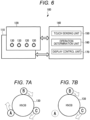
Fig. 7 is a diagram for describing an overview of aspects of the invention of the input display device according to an embodiment of the present invention. -
Fig. 8 is a diagram for describing a method of sensing a rotation amount of a finger touching a knob in an embodiment of the present invention. -
Fig. 9 is a diagram for describing a method of determining a rotation operation on a knob when the number of sensed fingers increases or decreases according to an embodiment of the present invention. -
Fig. 10A is an example of an operation flow of a sensing algorithm of a rotation operation of a knob of the input display device according to an embodiment of the present invention. -
Fig. 10B is an example of an operation flow of the sensing algorithm of the rotation operation on the knob of the input display device according to an embodiment of the present invention. - Embodiments of the present invention will be described. An input display device of the present invention provides an interface between a person and a machine. The input display device of the present invention is not particularly limited, but is applied to, for example, an electronic device equipped with a display with a touch panel on which a three-dimensional UI unit is formed. The electronic device equipped with the display with a touch panel is, for example, an in-vehicle device having a navigation function, an audio visual function, a television function, and the like.
- Next, embodiments of the present invention will be described in detail with reference to the drawings.
Fig. 6 is a block diagram illustrating a configuration of an input display device according to an embodiment of the present invention. Aninput display device 100 of the present embodiment includes adisplay 110 configured to display an image and a video, acapacitive touch panel 120 mounted on thedisplay 110, a three-dimensional UI unit (or an operation unit) 130 having one or a plurality of three-dimensional shapes attached to the front face of thetouch panel 120, and acontroller 140 that controls image display of thedisplay 110, touch sensing of atouch panel 120, and the like. - The
display 110 is not particularly limited, but includes, for example, a liquid crystal panel or an organic EL panel, and displays image data provided from thecontroller 140. For example, an icon representing an input operation of the three-dimensional UI unit 130 is displayed at the lower part of the three-dimensional UI unit 130. - The
touch panel 120 includes, for example, a plurality of sensors (sensing units) formed at positions where a plurality of X-side and Y-side electrode lines intersect, and the sensors sense a change in electrostatic capacitance when a user's finger, hand, or the like approaches or comes into contact with thetouch panel 120. Thetouch panel 120 is mounted on thedisplay 110 and provides an input interface for the user to make an input to an icon or the like displayed on thedisplay 110. - The
touch panel 120 further includes one or more three-dimensional UI units (operation units) 130 on the front face of the transparent panel.Fig. 6 illustrates an example in which four three-dimensional UI units 130 are attached at the lower part of thetouch panel 120, but the number and size of the three-dimensional UI units 130 are not particularly limited. The three-dimensional UI unit 130 may be made of a transparent material (for example, acrylic, polycarbonate, glass, and the like) so that an icon displayed on thedisplay 110 can be visually recognized. The bottom face of the three-dimensional UI unit 130 may be attached to thetouch panel 120 using, for example, a double-sided adhesive or may be integrally molded with a cover glass attached to the front face of thetouch panel 120. - Information regarding the position and shape of the three-dimensional UI unit 130 (for example, coordinates on the touch panel, shapes, sizes, and heights of the bottom face and the front face, and the like) is registered in a memory or the like in the
controller 140. For example, when the three-dimensional UI unit 130 is a cylindrical knob, the coordinates of the center of the bottom face of the knob, the radius or diameter of the bottom face/front face of the knob, the height of the side face, and the like are registered. When a finger approaching thetouch panel 120 is sensed, thecontroller 140 refers to the information about the registered position and shape of the three-dimensional UI unit 130 and determines whether the finger is a touch operation on the three-dimensional UI unit 130. - In the present embodiment, the three-
dimensional UI unit 130 includes at least a cylindrical knob or button (seeFig. 2 and the like) on which the user can perform a rotation operation (hereinafter, the three-dimensional UI unit 130 may be referred to as a knob 130). When performing a rotation operation on theknob 130, the user performs an operation of holding theknob 130 with one or a plurality of fingers and sliding a side face of theknob 130 with finger pads. When such a rotation operation is performed, the coordinates of the finger touching theknob 130 are sensed, the rotation amount of the finger is sensed based on the sensed coordinates of the finger, and the presence or absence of the rotation operation on the knob is determined from the sensed rotation amount. Details of the determination of the rotation operation will be described later. - The
controller 140 includes hardware and/or software resources, and performs overall processing of the input display device using, for example, an arithmetic processing unit, a microcontroller including a ROM/RAM, or the like. For example, display processing of thedisplay 110, touch sensing or touch operation determination (sense touch position and finger distance, sense rotation amount of finger touched by knob, and determine presence or absence of rotation operation) from an output value of thetouch panel 120, and processing of video display/video switching according to the touch sensing or the touch operation determination are performed. - As illustrated in
Fig. 6 , thecontroller 140 includes atouch sensing unit 150, anoperation determination unit 160, and adisplay control unit 170. Thetouch sensing unit 150 drives the plurality of electrode lines on the X side and/or the Y side of thetouch panel 120 at a constant cycle (for example, 60 fps (frames per second)), measures the electrostatic capacitance of the sensing unit of the driven electrode lines, senses the touch position of the finger or the like based on the measurement result, and provides the sensing result to theoperation determination unit 160. - The
operation determination unit 160 determines the presence or absence of a touch operation on thetouch panel 120 or a touch operation (for example, a rotation operation on the knob) on the three-dimensional UI unit 130 based on the sensing result of thetouch sensing unit 150. Here, the touch includes not only contact of the user's finger to thetouch panel 120 or the three-dimensional UI unit 130 but also approach of the finger to thetouch panel 120 or the three-dimensional UI unit 130. For example, when the user's finger touches or approaches thetouch panel 120, thetouch sensing unit 150 senses the presence or absence of a touch based on a change in electrostatic capacitance of a corresponding sensor, and similarly, when the user's finger touches or approaches the three-dimensional UI unit 130, the touch sensing unit senses the presence or absence of a touch on the three-dimensional UI unit 130 based on a change in electrostatic capacitance of a corresponding sensor. - The
display control unit 170 displays an image and a video on thedisplay 110, and displays a GUI image related to the operation of the three-dimensional UI unit 130 in an area where the three-dimensional UI unit 130 exists. In addition, thedisplay control unit 170 switches an image to be displayed on thedisplay 110 to another image in response to theoperation determination unit 160 determining that a touch operation has been performed. - Next, an outline of a sensing algorithm of the rotation operation on the knob by the
input display device 100 of the present embodiment will be described. In the present embodiment, the conventional problem is solved by an algorithm that can stably continue the rotation sensing even when the number of fingers sensed at the time of the rotation operation on the knob increases or decreases. - As illustrated in
Fig. 7A , when the fingers A, B, and C touching theknob 130 are sensed, all the coordinates of the fingers A, B, and C are observed, and rightward rotation or leftward rotation is determined from the movement direction of the coordinates. By observing all the finger, even when sensing of the finger A disappears on the way, the determination of rotation is continued by referring to the remaining sensed fingers B and C, for example, as illustrated inFig. 7B . - Since the amount of movement of the finger during the rotation operation is different for each finger, the rotation angle of the finger having the largest rotation amount is referred to. In
Fig. 7A , when the rotation amounts (amounts of movement) of the fingers are A > B > C, the finger A having the largest rotation amount is referred to, and the rotation operation on theknob 130 is determined based on the rotation amount of the finger A. However, it should be noted that the rotation amounts of the remaining fingers B and C are also continuously monitored. When sensing disappears due to, for example, the finger A being referred to being away from theknob 130, the rotation amount of the remaining finger B for which the sensing is being continued is referred to (because B > C). As described above, the knob rotation sensing is performed in consideration of the movement of the plurality of fingers and the increase or decrease in the number of sensed fingers. - Next, details of the
input display device 100 of the present embodiment will be described. First, a method of sensing the rotation amount of the finger will be described. As illustrated inFig. 8A , a 0° position serving as a reference is set with respect to the coordinates of the center point C of theknob 130, and an angle corresponding to a position when a finger touches the knob circumference can be calculated. In the example of the drawing, the right side is set to 0°, and the angle is set to increase counterclockwise. - A finger angle is sensed from coordinates on a circumference of the
knob 130 touched by a finger. For example, as illustrated inFig. 8B , when the coordinates of the finger touching theknob 130 are in the middle of the circumference between 0° and 90°, 45° is calculated as the finger angle. The relationship between the coordinates of the finger on the knob circumference and the finger angle is calculated using, for example, a trigonometric function. - Next, the rotation amount (change amount) is calculated from the amount of movement of the finger on the circumference. For example, as illustrated in
Fig. 8C , in a case where the finger moves to a point where the coordinates of the finger are 90°, that is, in a case where the finger moves from the position where the finger angle is 45° to the position where the finger angle is 90°, 45° is calculated as the rotation amount in accordance with the rotation operation on theknob 130. - Next, a method of determining the presence or absence of the rotation operation from the rotation amount will be described. In the present embodiment, in order to realize smooth rotation sensing even when the number of sensed fingers increases or decreases during the rotation operation on the knob, the presence or absence of the rotation operation is determined by looking at the magnitude of the amount of movements of all the fingers touching the knob in a composite manner.
- As described with reference to
Fig. 8B , thetouch sensing unit 150 measures the capacitance of each sensor of thetouch panel 120 at a constant measurement cycle, and senses the coordinates of the touch position of the finger from the measurement result. When the sensed coordinates of the finger correspond to the coordinate position of theknob 130 registered in advance, theoperation determination unit 160 determines that the finger touches theknob 130. When a plurality of fingers touches theknob 130, coordinates of touch positions of the plurality of fingers are sensed. When touch of a finger on theknob 130 is sensed, theoperation determination unit 160 calculates a finger angle of the touched finger. - As described with reference to
Fig. 8C , when the rotation operation is performed on theknob 130, the coordinates of the finger sensed bytouch sensing unit 150 change. Theoperation determination unit 160 calculates the finger angle from the changed coordinates of the finger, and calculates the rotation amount of the finger from the difference between the finger angles. - For example, as illustrated in
Fig. 9A , it is assumed that the touch of the fingers U1 to U4 on theknob 130 is sensed, the fingers U1, U2, and U3 rotate and move by +10°, and the finger U4 rotates and moves by + 15°. Assuming that the threshold value for determining the rotation of the knob is 15°, since the rotation amount of the finger U4 is +15°, theoperation determination unit 160 determines that theknob 130 has rotated clockwise. When it is determined that theknob 130 has rotated clockwise, the display of thegauge 50 increases by one step, as shown inFig. 2 . - On the other hand, when the rotation amount of each of the fingers U1 to U3 is +5° and the rotation amount of the finger U4 is +10° as illustrated in
Fig. 9B , and when the finger U4 having the largest rotation amount is away from theknob 130 before reaching the threshold value (when the sensing of the finger U4 disappears) as illustrated inFig. 9C , the count value of the rotation amount (+10°) of the finger U4 that is away is taken over to the remaining fingers U1, U2, and U3 during the sensing. That is, the fingers U1, U2, and U3 that are continuously sensed count the rotation amount of +5° at the time when the sensing of the finger U4 disappears, but all the rotation amounts of the fingers U1, U2, and U3 are updated to the rotation amount of +10° of the finger U4 that has disappeared. Thereafter, when the rotation amount newly counted by the fingers U1 to U3 is added to the updated rotation amount of +10° and +5° is counted as the new rotation amount of the finger U3, for example, as illustrated inFig. 9D , the total rotation amount of the finger U3 reaches +15°, and thus theoperation determination unit 160 determines that theknob 130 has been rotated. - When the sensing of the finger U4 is added as illustrated in
Fig. 9F while the rotation amounts of the fingers U1 and U2 are +5° and the rotation amount of the finger U3 is +10° as illustrated inFig. 9E , the rotation amount +10° counted by the finger U3 having the largest rotation amount is allocated to the added finger U4. At this time, the fingers U1 and U2 may maintain the counted rotation amount +5° as it is, or the rotation amounts of the fingers U1 and U2 may also be updated to the rotation amount +10° of the finger U3. - As described above, according to the present embodiment, since the presence or absence of the rotation operation on the knob is determined while monitoring the rotation amounts of all the fingers touching the
knob 130, it is possible to stably determine the rotation operation on the knob even if the number of sensed fingers changes. - Next, an example of a flow of an algorithm for determining the rotation operation on the knob in the input display device of the present embodiment is illustrated in
Figs. 10A and10B . First, the coordinates (x, y) of the touch position of the finger are sensed by thetouch sensing unit 150, and the operation determination unit stores the sensed coordinates in a variable for recording (S1). When the touch positions of a plurality of fingers are sensed, the coordinates of each finger are stored as a variable. Next, theoperation determination unit 160 calculates a finger angle (0 to 360°) on the knob circumference from the sensed coordinates of the finger, and stores the calculated finger angle in a variable for recording (S2). When the coordinates of the plurality of fingers are sensed, the respective finger angles are calculated, and the respective finger angles are stored as variables. - The
touch sensing unit 150 measures the electrostatic capacitance of the sensor of thetouch panel 120 at a constant cycle, and senses the coordinates of the touch position of the finger from the measurement result. Theoperation determination unit 160 determines whether thetouch sensing unit 150 continuously senses the coordinates of the finger in the knob sensing area (S3), and when it is determined that the coordinates of the finger are continuously sensed, the operation determination unit acquires the coordinates of the touch position of the finger from thetouch sensing unit 150 again (S4). When the coordinates are acquired, theoperation determination unit 160 determines whether the number of sensed fingers in step S4 is smaller than the number stored in the variable in step S1 (S5), and when the number of sensed fingers is not smaller than the number stored in the variable, the operation determination unit determines whether the number of sensed fingers is increased (S6). - When the number of sensed fingers has not increased in step S6, that is, when there is no change in the number of sensed fingers, the
operation determination unit 160 determines whether the sensing coordinates in step S4 and the sensing coordinates in step S1 are the same for any of the fingers (S7). In a case where the sensing coordinates of any of the fingers are the same, the finger does not move, and thus the processing returns to step S3. When the sensing coordinates are not the same, the rotation amount (amount of movement) of each finger is calculated from the difference between the finger angle on the circumference in step S2 and the finger angle calculated from step S4 for the finger whose coordinates have changed in step S7, and the rotation amount is added to a variable (S8). - Next, the
operation determination unit 160 determines whether there is a finger whose variable value of the rotation amount exceeds the threshold value (S9), and when there is a finger whose variable value exceeds the threshold value, it is determined that the rotation operation on the knob has been performed (S10). When it is determined that there is the presence of the rotation operation, theoperation determination unit 160 resets the rotation amount variable of each finger to the initial value (0) (S11). - On the other hand, in a case where the number of sensed fingers has decreased in step S5, the
operation determination unit 160 determines whether a rotation amount counted in the variable of the finger that was sensed and disappeared is the largest among the rotation amounts of all the fingers (S12). In a case where the rotation amount is the largest, the operation determination unit overwrites the rotation amount count values of all the continuously sensed fingers with the count value of the finger that was sensed and disappeared (S13), and the processing returns to step S3. - When the number of sensed fingers is increased in step S6, the
operation determination unit 160 allocates, to the added sensed finger, the largest value among the rotation amount count values of all the fingers continuously sensed and the variable values in steps S1 and S2 (S14), and the process proceeds to step S7. - The flow illustrated in
Figs. 10A and10B is an example for implementing an algorithm for determining the presence or absence of the rotation operation of the present embodiment, and the present invention is not necessarily limited to such a flow. In the above embodiment, 15° is used as the threshold value of the rotation amount for determining the presence or absence of the rotation operation on the knob. However, this is an example, and the threshold value may be another value. In the above embodiment, thecylindrical knob 130 is exemplified as the three-dimensional UI unit, but this is an example, and for example, other shapes such as a conical finger grip or a conical button may be used. - Embodiments of the present invention have been described in detail above. However, the present invention is not limited to the specific embodiments, and thus various modifications and alterations can be made in the scope of the claims.
-
- 30
- knob
- 40
- icon
- 50
- gauge
- 100
- input display device
- 110
- display
- 120
- touch panel
- 130
- three-dimensional UI unit (knob)
- 140
- controller
- U1 to U5
- finger
Claims (7)
- An input display device (100) comprising a display (110) configured to display an image, and a capacitive touch panel (120) attached to the display (110) and including at least one three-dimensional operation unit on a front face of the touch panel (120), further comprising:a sensing unit (150) configured to measure an electrostatic capacitance of the touch panel (120) and to sense an operation on the touch panel (120) based on the measured electrostatic capacitance, whereinthe sensing unit (150) is configured to sense rotation amounts of all fingers touching the operation unit, and to determine that a rotation operation on the operation unit is performed when a sensed rotation amount of any of the fingers reaches a threshold value.
- The input display device (100) according to claim 1, wherein, in a case where sensing of a finger disappears before a rotation amount of the finger having a largest rotation amount reaches the threshold value, the sensing unit (150) is configured to update rotation amounts of remaining fingers to a rotation amount of the finger having the largest rotation amount.
- The input display device (100) according to claim 1 or 2, wherein, in a case where sensing of a finger touching the operation unit is added in a middle, the sensing unit (150) is configured to allocate a rotation amount of a finger having a largest rotation amount to a rotation amount of an added finger.
- The input display device (100) according to one of claims 1-3, wherein the sensing unit (150) is configured to reset a sensed rotation amount of a finger when determining that a rotation operation on the operation unit is performed.
- The input display device (100) according to one of claims 1-4, further comprising a display unit configured to display a gauge (50), corresponding to a rotation operation, around the operation unit of the display (110).
- The input display device (100) according to claim 5, wherein the display unit is configured to display an icon (12) representing an input operation at a corresponding position of the operation unit of the display (110).
- The input display device (100) according to one of claims 1 - 6, wherein the operation unit has a cylindrical knob shape, a cylindrical button shape, or a cylindrical finger grip shape.
Applications Claiming Priority (1)
| Application Number | Priority Date | Filing Date | Title |
|---|---|---|---|
| JP2022202863A JP2024087947A (en) | 2022-12-20 | 2022-12-20 | Input display device |
Publications (2)
| Publication Number | Publication Date |
|---|---|
| EP4394564A1 true EP4394564A1 (en) | 2024-07-03 |
| EP4394564B1 EP4394564B1 (en) | 2026-04-22 |
Family
ID=89222166
Family Applications (1)
| Application Number | Title | Priority Date | Filing Date |
|---|---|---|---|
| EP23216276.8A Active EP4394564B1 (en) | 2022-12-20 | 2023-12-13 | Input display device |
Country Status (4)
| Country | Link |
|---|---|
| US (1) | US12277280B2 (en) |
| EP (1) | EP4394564B1 (en) |
| JP (1) | JP2024087947A (en) |
| CN (1) | CN118226980A (en) |
Families Citing this family (1)
| Publication number | Priority date | Publication date | Assignee | Title |
|---|---|---|---|---|
| JP2025071415A (en) * | 2023-10-23 | 2025-05-08 | アルプスアルパイン株式会社 | Input display device |
Citations (6)
| Publication number | Priority date | Publication date | Assignee | Title |
|---|---|---|---|---|
| US20140313168A1 (en) * | 2010-04-23 | 2014-10-23 | Handscape Inc. | Method for user input from alternative touchpads of a computerized system |
| US20180364853A1 (en) * | 2017-06-15 | 2018-12-20 | Microsoft Technology Licensing, Llc | Hover-based user-interactions with virtual objects within immersive environments |
| WO2020208794A1 (en) * | 2019-04-11 | 2020-10-15 | 三菱電機株式会社 | Input device, input-receiving device, and input system |
| JP2020190832A (en) | 2019-05-20 | 2020-11-26 | 株式会社デンソー | Input display device |
| FR3115618A1 (en) * | 2020-10-26 | 2022-04-29 | Hap2U | Three-dimensional touch interface with haptic feedback |
| WO2022113253A1 (en) * | 2020-11-27 | 2022-06-02 | 三菱電機株式会社 | Display system and display method |
Family Cites Families (10)
| Publication number | Priority date | Publication date | Assignee | Title |
|---|---|---|---|---|
| KR100958491B1 (en) * | 2004-07-30 | 2010-05-17 | 애플 인크. | Mode-based graphical user interface for touch-sensitive input devices |
| US8766910B2 (en) * | 2007-07-04 | 2014-07-01 | Cypress Semiconductor Corporation | Capacitive sensing control knob |
| US8810514B2 (en) * | 2010-02-12 | 2014-08-19 | Microsoft Corporation | Sensor-based pointing device for natural input and interaction |
| DE102013021093B4 (en) * | 2013-12-18 | 2023-11-30 | Diehl Ako Stiftung & Co. Kg | Operating device |
| JP6311439B2 (en) * | 2014-05-09 | 2018-04-18 | 株式会社デンソー | Operating device |
| EP3144783A4 (en) * | 2014-05-15 | 2017-08-02 | Panasonic Intellectual Property Management Co., Ltd. | Operation knob and display device in which same is used |
| WO2018225206A1 (en) * | 2017-06-08 | 2018-12-13 | 三菱電機株式会社 | Touch input determination device, touch panel input device, touch input determination method, and touch input determination program |
| US10884520B2 (en) * | 2018-09-06 | 2021-01-05 | Sharp Kabushiki Kaisha | Input detecting device |
| JP7222960B2 (en) * | 2020-10-27 | 2023-02-15 | 株式会社ホンダアクセス | touch panel device |
| JP2022161369A (en) * | 2021-04-08 | 2022-10-21 | 日本精機株式会社 | touch type operation device |
-
2022
- 2022-12-20 JP JP2022202863A patent/JP2024087947A/en active Pending
-
2023
- 2023-11-10 US US18/506,465 patent/US12277280B2/en active Active
- 2023-12-12 CN CN202311697613.0A patent/CN118226980A/en active Pending
- 2023-12-13 EP EP23216276.8A patent/EP4394564B1/en active Active
Patent Citations (7)
| Publication number | Priority date | Publication date | Assignee | Title |
|---|---|---|---|---|
| US20140313168A1 (en) * | 2010-04-23 | 2014-10-23 | Handscape Inc. | Method for user input from alternative touchpads of a computerized system |
| US20180364853A1 (en) * | 2017-06-15 | 2018-12-20 | Microsoft Technology Licensing, Llc | Hover-based user-interactions with virtual objects within immersive environments |
| WO2020208794A1 (en) * | 2019-04-11 | 2020-10-15 | 三菱電機株式会社 | Input device, input-receiving device, and input system |
| JP2020190832A (en) | 2019-05-20 | 2020-11-26 | 株式会社デンソー | Input display device |
| FR3115618A1 (en) * | 2020-10-26 | 2022-04-29 | Hap2U | Three-dimensional touch interface with haptic feedback |
| US20230400924A1 (en) * | 2020-10-26 | 2023-12-14 | Hap2U | Three-dimensional touch interface providing haptic feedback |
| WO2022113253A1 (en) * | 2020-11-27 | 2022-06-02 | 三菱電機株式会社 | Display system and display method |
Also Published As
| Publication number | Publication date |
|---|---|
| US12277280B2 (en) | 2025-04-15 |
| JP2024087947A (en) | 2024-07-02 |
| EP4394564B1 (en) | 2026-04-22 |
| US20240201800A1 (en) | 2024-06-20 |
| CN118226980A (en) | 2024-06-21 |
Similar Documents
| Publication | Publication Date | Title |
|---|---|---|
| US20110221684A1 (en) | Touch-sensitive input device, mobile device and method for operating a touch-sensitive input device | |
| CN103210361B (en) | touch sensitive input | |
| CN101699387B (en) | Non-touch interactive system and method | |
| US8674947B2 (en) | Lateral pressure sensors for touch screens | |
| US20130154933A1 (en) | Force touch mouse | |
| EP2918440A1 (en) | Vehicle operation apparatus | |
| US20120038496A1 (en) | Gesture-enabled keyboard and associated apparatus and computer-readable storage medium | |
| WO2009142880A1 (en) | Proximity sensor device and method with subregion based swipethrough data entry | |
| CN101751222A (en) | Information processing apparatus, information processing method, and program | |
| EP2474890A1 (en) | Virtual keyboard configuration putting fingers in rest positions on a multitouch screen, calibrating key positions thereof | |
| EP4394564A1 (en) | Input display device | |
| JP2012099005A (en) | Input device, input method, and input program | |
| JP7666779B2 (en) | Input Devices | |
| KR101154137B1 (en) | User interface for controlling media using one finger gesture on touch pad | |
| EP4354264A1 (en) | Input display device | |
| CN116700587A (en) | input device | |
| JP5062898B2 (en) | User interface device | |
| CN103543921B (en) | Information processing apparatus, information processing method, and computer program | |
| EP4383053A1 (en) | Input display device | |
| EP4546095A1 (en) | Input display device | |
| EP4354263B1 (en) | Input display device | |
| US11586347B2 (en) | Palm-based graphics change | |
| WO2024232150A1 (en) | Non-contact input device | |
| WO2024232147A1 (en) | Non-contact input apparatus and input assistance application | |
| JP2025068911A (en) | Input display device |
Legal Events
| Date | Code | Title | Description |
|---|---|---|---|
| PUAI | Public reference made under article 153(3) epc to a published international application that has entered the european phase |
Free format text: ORIGINAL CODE: 0009012 |
|
| STAA | Information on the status of an ep patent application or granted ep patent |
Free format text: STATUS: THE APPLICATION HAS BEEN PUBLISHED |
|
| AK | Designated contracting states |
Kind code of ref document: A1 Designated state(s): AL AT BE BG CH CY CZ DE DK EE ES FI FR GB GR HR HU IE IS IT LI LT LU LV MC ME MK MT NL NO PL PT RO RS SE SI SK SM TR |
|
| STAA | Information on the status of an ep patent application or granted ep patent |
Free format text: STATUS: REQUEST FOR EXAMINATION WAS MADE |
|
| 17P | Request for examination filed |
Effective date: 20241218 |
|
| GRAP | Despatch of communication of intention to grant a patent |
Free format text: ORIGINAL CODE: EPIDOSNIGR1 |
|
| STAA | Information on the status of an ep patent application or granted ep patent |
Free format text: STATUS: GRANT OF PATENT IS INTENDED |
|
| RIC1 | Information provided on ipc code assigned before grant |
Ipc: G06F 3/0362 20130101AFI20260128BHEP Ipc: G06F 3/044 20060101ALI20260128BHEP Ipc: G06F 3/039 20130101ALI20260128BHEP Ipc: G06F 3/04847 20220101ALI20260128BHEP Ipc: G06F 3/04883 20220101ALI20260128BHEP Ipc: G06F 3/041 20060101ALI20260128BHEP |
|
| INTG | Intention to grant announced |
Effective date: 20260204 |
|
| GRAS | Grant fee paid |
Free format text: ORIGINAL CODE: EPIDOSNIGR3 |
|
| GRAA | (expected) grant |
Free format text: ORIGINAL CODE: 0009210 |
|
| STAA | Information on the status of an ep patent application or granted ep patent |
Free format text: STATUS: THE PATENT HAS BEEN GRANTED |
|
| AK | Designated contracting states |
Kind code of ref document: B1 Designated state(s): AL AT BE BG CH CY CZ DE DK EE ES FI FR GB GR HR HU IE IS IT LI LT LU LV MC ME MK MT NL NO PL PT RO RS SE SI SK SM TR |
|
| REG | Reference to a national code |
Ref country code: CH Ref legal event code: F10 Free format text: ST27 STATUS EVENT CODE: U-0-0-F10-F00 (AS PROVIDED BY THE NATIONAL OFFICE) Effective date: 20260422 Ref country code: GB Ref legal event code: FG4D |
|
| P01 | Opt-out of the competence of the unified patent court (upc) registered |
Free format text: CASE NUMBER: UPC_APP_0010382_4394564/2026 Effective date: 20260319 |