EP4394550A1 - Foldable display device - Google Patents
Foldable display device Download PDFInfo
- Publication number
- EP4394550A1 EP4394550A1 EP23218617.1A EP23218617A EP4394550A1 EP 4394550 A1 EP4394550 A1 EP 4394550A1 EP 23218617 A EP23218617 A EP 23218617A EP 4394550 A1 EP4394550 A1 EP 4394550A1
- Authority
- EP
- European Patent Office
- Prior art keywords
- bar
- flap
- display device
- foldable display
- gear
- Prior art date
- Legal status (The legal status is an assumption and is not a legal conclusion. Google has not performed a legal analysis and makes no representation as to the accuracy of the status listed.)
- Granted
Links
Images




Classifications
-
- G—PHYSICS
- G06—COMPUTING OR CALCULATING; COUNTING
- G06F—ELECTRIC DIGITAL DATA PROCESSING
- G06F1/00—Details not covered by groups G06F3/00 - G06F13/00 and G06F21/00
- G06F1/16—Constructional details or arrangements
- G06F1/1613—Constructional details or arrangements for portable computers
- G06F1/1633—Constructional details or arrangements of portable computers not specific to the type of enclosures covered by groups G06F1/1615 - G06F1/1626
- G06F1/1637—Details related to the display arrangement, including those related to the mounting of the display in the housing
- G06F1/1652—Details related to the display arrangement, including those related to the mounting of the display in the housing the display being flexible, e.g. mimicking a sheet of paper, or rollable
-
- G—PHYSICS
- G09—EDUCATION; CRYPTOGRAPHY; DISPLAY; ADVERTISING; SEALS
- G09F—DISPLAYING; ADVERTISING; SIGNS; LABELS OR NAME-PLATES; SEALS
- G09F9/00—Indicating arrangements for variable information in which the information is built-up on a support by selection or combination of individual elements
- G09F9/30—Indicating arrangements for variable information in which the information is built-up on a support by selection or combination of individual elements in which the desired character or characters are formed by combining individual elements
- G09F9/301—Indicating arrangements for variable information in which the information is built-up on a support by selection or combination of individual elements in which the desired character or characters are formed by combining individual elements flexible foldable or roll-able electronic displays, e.g. thin LCD, OLED
-
- F—MECHANICAL ENGINEERING; LIGHTING; HEATING; WEAPONS; BLASTING
- F16—ENGINEERING ELEMENTS AND UNITS; GENERAL MEASURES FOR PRODUCING AND MAINTAINING EFFECTIVE FUNCTIONING OF MACHINES OR INSTALLATIONS; THERMAL INSULATION IN GENERAL
- F16C—SHAFTS; FLEXIBLE SHAFTS; ELEMENTS OR CRANKSHAFT MECHANISMS; ROTARY BODIES OTHER THAN GEARING ELEMENTS; BEARINGS
- F16C11/00—Pivots; Pivotal connections
- F16C11/04—Pivotal connections
-
- F—MECHANICAL ENGINEERING; LIGHTING; HEATING; WEAPONS; BLASTING
- F16—ENGINEERING ELEMENTS AND UNITS; GENERAL MEASURES FOR PRODUCING AND MAINTAINING EFFECTIVE FUNCTIONING OF MACHINES OR INSTALLATIONS; THERMAL INSULATION IN GENERAL
- F16C—SHAFTS; FLEXIBLE SHAFTS; ELEMENTS OR CRANKSHAFT MECHANISMS; ROTARY BODIES OTHER THAN GEARING ELEMENTS; BEARINGS
- F16C11/00—Pivots; Pivotal connections
- F16C11/04—Pivotal connections
- F16C11/12—Pivotal connections incorporating flexible connections, e.g. leaf springs
-
- F—MECHANICAL ENGINEERING; LIGHTING; HEATING; WEAPONS; BLASTING
- F16—ENGINEERING ELEMENTS AND UNITS; GENERAL MEASURES FOR PRODUCING AND MAINTAINING EFFECTIVE FUNCTIONING OF MACHINES OR INSTALLATIONS; THERMAL INSULATION IN GENERAL
- F16H—GEARING
- F16H57/00—General details of gearing
- F16H57/02—Gearboxes; Mounting gearing therein
-
- G—PHYSICS
- G06—COMPUTING OR CALCULATING; COUNTING
- G06F—ELECTRIC DIGITAL DATA PROCESSING
- G06F1/00—Details not covered by groups G06F3/00 - G06F13/00 and G06F21/00
- G06F1/16—Constructional details or arrangements
- G06F1/1613—Constructional details or arrangements for portable computers
- G06F1/1633—Constructional details or arrangements of portable computers not specific to the type of enclosures covered by groups G06F1/1615 - G06F1/1626
- G06F1/1637—Details related to the display arrangement, including those related to the mounting of the display in the housing
- G06F1/1641—Details related to the display arrangement, including those related to the mounting of the display in the housing the display being formed by a plurality of foldable display components
-
- G—PHYSICS
- G06—COMPUTING OR CALCULATING; COUNTING
- G06F—ELECTRIC DIGITAL DATA PROCESSING
- G06F1/00—Details not covered by groups G06F3/00 - G06F13/00 and G06F21/00
- G06F1/16—Constructional details or arrangements
- G06F1/1613—Constructional details or arrangements for portable computers
- G06F1/1633—Constructional details or arrangements of portable computers not specific to the type of enclosures covered by groups G06F1/1615 - G06F1/1626
- G06F1/1675—Miscellaneous details related to the relative movement between the different enclosures or enclosure parts
- G06F1/1681—Details related solely to hinges
-
- H—ELECTRICITY
- H04—ELECTRIC COMMUNICATION TECHNIQUE
- H04M—TELEPHONIC COMMUNICATION
- H04M1/00—Substation equipment, e.g. for use by subscribers
- H04M1/02—Constructional features of telephone sets
- H04M1/0202—Portable telephone sets, e.g. cordless phones, mobile phones or bar type handsets
- H04M1/0206—Portable telephones comprising a plurality of mechanically joined movable body parts, e.g. hinged housings
- H04M1/0208—Portable telephones comprising a plurality of mechanically joined movable body parts, e.g. hinged housings characterized by the relative motions of the body parts
- H04M1/0214—Foldable telephones, i.e. with body parts pivoting to an open position around an axis parallel to the plane they define in closed position
- H04M1/0216—Foldable in one direction, i.e. using a one degree of freedom hinge
- H04M1/022—The hinge comprising two parallel pivoting axes
-
- H—ELECTRICITY
- H04—ELECTRIC COMMUNICATION TECHNIQUE
- H04M—TELEPHONIC COMMUNICATION
- H04M1/00—Substation equipment, e.g. for use by subscribers
- H04M1/02—Constructional features of telephone sets
- H04M1/0202—Portable telephone sets, e.g. cordless phones, mobile phones or bar type handsets
- H04M1/0206—Portable telephones comprising a plurality of mechanically joined movable body parts, e.g. hinged housings
- H04M1/0208—Portable telephones comprising a plurality of mechanically joined movable body parts, e.g. hinged housings characterized by the relative motions of the body parts
- H04M1/0235—Slidable or telescopic telephones, i.e. with a relative translation movement of the body parts; Telephones using a combination of translation and other relative motions of the body parts
- H04M1/0237—Sliding mechanism with one degree of freedom
-
- H—ELECTRICITY
- H05—ELECTRIC TECHNIQUES NOT OTHERWISE PROVIDED FOR
- H05K—PRINTED CIRCUITS; CASINGS OR CONSTRUCTIONAL DETAILS OF ELECTRIC APPARATUS; MANUFACTURE OF ASSEMBLAGES OF ELECTRICAL COMPONENTS
- H05K5/00—Casings, cabinets or drawers for electric apparatus
- H05K5/02—Details
- H05K5/0217—Mechanical details of casings
- H05K5/0226—Hinges
-
- H—ELECTRICITY
- H10—SEMICONDUCTOR DEVICES; ELECTRIC SOLID-STATE DEVICES NOT OTHERWISE PROVIDED FOR
- H10K—ORGANIC ELECTRIC SOLID-STATE DEVICES
- H10K59/00—Integrated devices, or assemblies of multiple devices, comprising at least one organic light-emitting element covered by group H10K50/00
- H10K59/80—Constructional details
- H10K59/87—Passivation; Containers; Encapsulations
-
- H—ELECTRICITY
- H10—SEMICONDUCTOR DEVICES; ELECTRIC SOLID-STATE DEVICES NOT OTHERWISE PROVIDED FOR
- H10K—ORGANIC ELECTRIC SOLID-STATE DEVICES
- H10K77/00—Constructional details of devices covered by this subclass and not covered by groups H10K10/80, H10K30/80, H10K50/80 or H10K59/80
- H10K77/10—Substrates, e.g. flexible substrates
- H10K77/111—Flexible substrates
-
- H—ELECTRICITY
- H04—ELECTRIC COMMUNICATION TECHNIQUE
- H04M—TELEPHONIC COMMUNICATION
- H04M1/00—Substation equipment, e.g. for use by subscribers
- H04M1/02—Constructional features of telephone sets
- H04M1/0202—Portable telephone sets, e.g. cordless phones, mobile phones or bar type handsets
- H04M1/026—Details of the structure or mounting of specific components
- H04M1/0266—Details of the structure or mounting of specific components for a display module assembly
- H04M1/0268—Details of the structure or mounting of specific components for a display module assembly including a flexible display panel
-
- H—ELECTRICITY
- H10—SEMICONDUCTOR DEVICES; ELECTRIC SOLID-STATE DEVICES NOT OTHERWISE PROVIDED FOR
- H10K—ORGANIC ELECTRIC SOLID-STATE DEVICES
- H10K2102/00—Constructional details relating to the organic devices covered by this subclass
- H10K2102/301—Details of OLEDs
- H10K2102/311—Flexible OLED
Definitions
- the present disclosure relates to a foldable display device, and more particularly, to a foldable display device having a hinge structure capable of being bidirectionally folded.
- portable terminals such as wireless terminals, personal digital assistants (PDAs), portable multimedia players (PMPs), and electronic notebooks have been miniaturized in size for portability.
- PDAs personal digital assistants
- PMPs portable multimedia players
- electronic notebooks have been miniaturized in size for portability.
- users require large-sized and wide screens of display parts because the users want to receive various types of information, such as text information, videos, still images, MP3s, and games through the screens of the portable terminals.
- miniaturization of the portable terminal leads to a decrease in size of the screen of the display part, there is a limitation in meeting the two requirements.
- An object to be achieved by one or more embodiments of the present disclosure is to provide an improved display device, which can address the limitations associated with the related art.
- the inventors of the present disclosure have invented a structure that uses a mechanism including a hinge provided in a region in which a display panel is folded.
- a hinge structure in the related art can be folded only in one direction, and it is difficult to implement both an in-folding state in which a display panel is disposed inward and an out-folding state in which the display panel is disposed outward.
- the inventors have recognized that even though a hinge capable of implementing both the in-folding state and the out-folding state is applied, it is difficult to cope with both damage to the display panel occurring in the in-folding state and damage to the display panel occurring in the out-folding state caused by repeated folding operations.
- An object to be achieved by the present disclosure is to provide a bidirectionally foldable display device capable of implementing both an in-folding state and an out-folding state.
- Another object to be achieved by the present disclosure is to provide a foldable display device capable of suppressing damage to a display panel caused when pressure is applied to the display panel exposed during a process of implementing an out-folding state. That is, the foldable display device of the present invention can be out-folded without causing damage to the display panel, or at least causing minimal damage to the display panel.
- Still another object to be achieved by the present disclosure is to provide a foldable display device capable of minimizing the occurrence of cracks and/or creases in a display panel and inhibiting excessive stress from being applied to the display panel because of a small radius of curvature during an in-folding operation.
- Yet another object to be achieved by the present disclosure is to provide a foldable display device capable of reducing strain applied to a portion of a display panel to which highest pressure is applied during an in-folding operation and an out-folding operation.
- Still yet another object to be achieved by the present disclosure is to provide a foldable display device capable of improving durability by inhibiting a display panel and a support structure from being spaced apart from each other during an out-folding operation.
- Another further object to be achieved by the present disclosure is to provide a foldable display device having excellent durability even though a folding operation is repeated.
- a foldable display device comprises a display panel, a first set housing and a second set housing disposed to face each other in a first direction and respectively supporting two different portions of the display panel, and a hinge assembly disposed between the first set housing and the second set housings and configured to fold and unfold the first set housing and the second set housing.
- the hinge assembly comprises a mid bar disposed between the first set housing and the second set housing and having a shape extending in a second direction perpendicular to the first direction, a first flap bar disposed between the first set housing and the mid bar, a second flap bar disposed between the second set housing and the mid bar, a bending coupler having a bent rod shape and having one side connected to the second flap bar, a semicircular disc connected to the other side of the bending coupler and including a flat portion having a planar shape, and an arc portion having a curved arc surface, the semicircular disc being configured to rotate about a central axis, a gear housing configured to accommodate the semicircular disc and accommodate an end of the mid bar, a spring member disposed at the end of the mid bar and accommodated in the gear housing, a first coupler and a second coupler respectively including first connection portions protruding toward the first flap bar and a second flap bar in the second direction, and second connection portions protruding in a direction opposite to the direction of
- the present disclosure can implement the bidirectionally foldable display device capable of performing both the in-folding operation and the out-folding operation.
- the rounded quadrangular (e.g., rounded rectangle) edge can be formed in the folding area during the out-folding operation, thereby suppressing damage to the display panel caused by pressure applied to the display panel. That is, due to a shape and design of the folding area, pressure and/or force applied to the display panel during various folding operations can be completely suppressed or at least greatly reduced.
- the display panel can be disposed in an omega ( ⁇ ) shape during the in-folding operation, the radius of curvature of the display panel in the folding area can be increased, and the stress applied to the folded display panel can be reduced.
- the support body which varies in position, can be used to support the display panel in the display area in both the out-folding state and the in-folding state, thereby inhibiting the display panel from being creased and/or cracked.
- the reliability of the display device can be improved and damage to the display panel can be minimized even though the folding operation is repeated.
- first, second, and the like are used for describing various components, these components are not confined by these terms, and may not define order or sequence. These terms are merely used for distinguishing one component from the other components. Therefore, a first component to be mentioned below can be a second component in a technical concept of the present disclosure.
- FIGS. 1 and 2 are views for explaining (i.e., illustrating) a foldable display device according to an embodiment of the present disclosure.
- FIG. 1 is a perspective view of the foldable display device according to the embodiment of the present disclosure.
- FIG. 2 is a top plan view illustrating a part of a configuration of the foldable display device according to the embodiment of the present disclosure.
- a foldable display device 100 can include set housings 110 and 120, a hinge assembly 200, a display panel 130, and a bezel cover 140.
- FIGS. 1 and 2 briefly illustrate components of the foldable display device 100. However, various components for substantially operating the foldable display device 100 can be further included.
- the foldable display device 100 according to the embodiment of the present disclosure can be folded at a particular angle (e.g., any particular angle) in accordance with a user's intention.
- the foldable display device can be completely folded or unfolded in accordance with the user's intention.
- the foldable display device can be unfolded or folded in an in-folding state or an inner-folding state in which the display panel is disposed inward.
- the foldable display device can be unfolded or folded in an out-folding state in which the display panel is disposed outward.
- the foldable display device 100 according to the embodiment of the present disclosure is a bidirectionally foldable display device capable of being bidirectionally folded and freely implementing the in-folding state and the out-folding state in accordance with the user's intention.
- the first set housing 110 and the second set housing 120 can be disposed to be spaced apart from each other with the hinge assembly 200 interposed therebetween.
- the first set housing 110 and the second set housing 120 can be disposed to face each other in a width direction (an X-axis direction or a first direction) with the hinge assembly 200 interposed therebetween.
- the first set housing 110 and the second set housing 120 can be respectively disposed in one side area and the other side area in which the foldable display device 100 of according to the embodiment of the present disclosure is folded and unfolded. That is, the foldable display device 100 according to the embodiment of the present disclosure can be folded and unfolded about any area between the first set housing 110 and the second set housing 120 by an external force applied by the user.
- the set housings 110 and 120 can each include a support body, a frame, and a fastening part.
- the first set housing 110 includes a first support body 112, a first frame 114, and a first fastening part 116
- the second set housing 120 includes a second support body 122, a second frame 124, and a second fastening part 126.
- the first fastening part 116 and the second fastening part 126 can be in the form of a flange or bracket.
- the support body and the frame can have structures that are provided separately and assembled to each other. Alternatively, the support body and the frame can have a single structure connected continuously.
- FIG. 2 illustrates the structure in which the first support body 112 and the first frame 114 are configured as a single structure connected continuously, and the second support body 122 and the second frame 124 are configured as a single structure connected continuously.
- the present disclosure is not limited thereto.
- the first fastening part 116 and the second fastening part 126 are provided on the first frame 114 and the second frame 124 and are coupled to the hinge assembly 200.
- the first fastening part 116 is provided at upper and lower ends of the first frame 114 disposed adjacent to the first flap bar 220a
- the second fastening part 126 is provided at upper and lower ends of the second frame 124 disposed adjacent to the second flap bar 220b.
- the first fastening part 116 and the second fastening part 126 are respectively fastened to a first gear arm 290a and a second gear arm 290b of the hinge assembly 200 that will be described below.
- the first fastening part 116 and the second fastening part 126 can be disposed to face each other in a folded state.
- the foldable display device 100 can be folded so that a particular folding angle is defined between the first set housing 110 and the second set housing 120. That is, FIGS. 1 and 2 illustrate that the foldable display device is completely unfolded so that an angle of 180° is defined between the first set housing 110 and the second set housing 120. However, the foldable display device 100 can be folded at a particular angle. In this case, the display panel 130, on which the first set housing 110 and the second set housing 120 are disposed, can be folded at a particular angle when the first set housing 110 and the second set housing 120 are folded.
- FIG. 3 is an enlarged exploded perspective view of part A in FIG. 2 .
- FIG. 3 is an exploded perspective view of the hinge assembly 200.
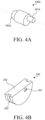
- FIG. 4A is a perspective view illustrating a structure of a first coupler of the foldable display device according to the embodiment of the present disclosure.
- FIG. 4B is a perspective view illustrating a structure of a semicircular disc of the foldable display device according to the embodiment of the present disclosure.
- FIG. 4C is a perspective view illustrating one side portion of a gear housing of the foldable display device according to the embodiment of the present disclosure.
- FIG. 4D is a perspective view illustrating the other side portion of the gear housing of the foldable display device according to the embodiment of the present disclosure.
- FIG. 4E is a perspective view illustrating a structure in which constituent elements of the foldable display device according to the embodiment of the present disclosure are coupled in the gear housing.
- the hinge assembly 200 includes the mid bar 210, the first flap bar 220a, the second flap bar 220b, bending couplers 230, first couplers 240a, second couplers 240b, semicircular discs 250, spring members 260, gear housings 270, first rotary gears 280a, second rotary gears 280b, the first gear arms 290a, and the second gear arms 290b.
- FIG. 3 illustrates only one of the two hinge assemblies of the present invention, with each hinge assembly being disposed on a respective side of the foldable display device 100.
- the mid bar 210 is disposed between the first set housing 110 and the second set housing 120.
- the mid bar 210 can have a flat shape elongated in a longitudinal direction (a Y-axis direction or a second direction).
- a top surface of the mid bar 210 has a flat shape to support the display panel 130.
- the mid bar 210 can move upward or downward in a thickness direction (the Z-axis direction or a third direction).
- the mid bar 210 can move upward or downward to fold or unfold the first set housing 110 and the second set housing 120.
- the upward or downward movement of the mid bar 210 will be described below with reference to a folding embodiment of the foldable display device according to the embodiment of the present disclosure.
- the bending coupler 230 provides a force to the right side by means of the motion of the second flap bar 220b, and the semicircular disc 250, which receives the force from the bending coupler 230, rotates counterclockwise. Therefore, the semicircular disc 250 is positioned at the upper side in the third accommodation portion of the gear housing 270. As illustrated in FIG. 5B , a part of the arc portion 253 is still positioned below the mid bar 210 even though the arc portion 253 of the semicircular disc 250 rotates. Therefore, the arc portion 253 of the semicircular disc 250 consistently supports the mid bar 210.
- the two opposite sides of each of the first and second flap bars 220a and 220b each have a rounded quadrangular (rounded rectangle) shape as the first and second flap bars 220a and 220b are folded.
- One side portion of each of the first flap bar and the second flap bar adjacent to the mid bar can be connected to the gear housing, the other side portion of the first flap bar adjacent to the first set housing can be connected to the first connection portion of the first coupler, and the other side portion of the second flap bar adjacent to the second set housing can be connected to the first connection portion of the second coupler.
- each of the first flap bar and the second flap bar can rotate about one side portion of each of the first flap bar and the second flap bar as a rotation axis.
- the semicircular disc can further comprise a third insertion groove configured to be connected to a protruding portion formed at the other side of the bending coupler.
- the arc portion can be disposed to correspond to an inner surface of the third accommodation portion.
- Various embodiments described herein may be implemented in a computer-readable medium using, for example, software, hardware, or some combination thereof.
- the embodiments described herein may be implemented within one or more of Application Specific Integrated Circuits (ASICs), Digital Signal Processors (DSPs), Digital Signal Processing Devices (DSPDs), Programmable Logic Devices (PLDs), Field Programmable Gate Arrays (FPGAs), processors, controllers, micro-controllers, microprocessors, other electronic units designed to perform the functions described herein, or a selective combination thereof. In some cases, such embodiments are implemented by the controller.
- ASICs Application Specific Integrated Circuits
- DSPs Digital Signal Processors
- DSPDs Digital Signal Processing Devices
- PLDs Programmable Logic Devices
- FPGAs Field Programmable Gate Arrays
- processors controllers, micro-controllers, microprocessors, other electronic units designed to perform the functions described herein, or a selective combination thereof.
- controllers micro-controllers, microprocess
Landscapes
- Engineering & Computer Science (AREA)
- General Engineering & Computer Science (AREA)
- Theoretical Computer Science (AREA)
- Computer Hardware Design (AREA)
- Physics & Mathematics (AREA)
- General Physics & Mathematics (AREA)
- Mechanical Engineering (AREA)
- Human Computer Interaction (AREA)
- Microelectronics & Electronic Packaging (AREA)
- Signal Processing (AREA)
- Devices For Indicating Variable Information By Combining Individual Elements (AREA)
Abstract
Description
- This application claims priority to
Korean Patent Application No. 10-2022-0190083 filed on December 30, 2022 - The present disclosure relates to a foldable display device, and more particularly, to a foldable display device having a hinge structure capable of being bidirectionally folded.
- Recently, portable terminals such as wireless terminals, personal digital assistants (PDAs), portable multimedia players (PMPs), and electronic notebooks have been miniaturized in size for portability. However, users require large-sized and wide screens of display parts because the users want to receive various types of information, such as text information, videos, still images, MP3s, and games through the screens of the portable terminals. However, because the miniaturization of the portable terminal leads to a decrease in size of the screen of the display part, there is a limitation in meeting the two requirements.
- To overcome the above-noted limitations, recently, flexible display devices, such as bendable display devices or foldable display devices, have been developed.
- The flexible display device can be implemented by configuring a substrate by using a plastic material. That is, the substrate of the flexible display device can comprise a flexible (e.g., elastic material). The flexible display device can be more conveniently carried by a user when the flexible display device is folded, and the flexible display device can implement a large screen when the flexible display device is unfolded. Therefore, the flexible display devices can be applied to various fields, such as televisions and monitors, as well as mobile devices such as mobile phones, electronic books, and electronic newspapers. Known foldable display device can only fold in a single direction, and there is need for foldable display devices that can fold in multiple directions to provide additional display configurations.
- An object to be achieved by one or more embodiments of the present disclosure is to provide an improved display device, which can address the limitations associated with the related art.
- To implement a foldable display device among flexible display devices, the inventors of the present disclosure have invented a structure that uses a mechanism including a hinge provided in a region in which a display panel is folded. However, the inventors have recognized that a hinge structure in the related art can be folded only in one direction, and it is difficult to implement both an in-folding state in which a display panel is disposed inward and an out-folding state in which the display panel is disposed outward.
- In addition, the inventors have recognized that even though a hinge capable of implementing both the in-folding state and the out-folding state is applied, it is difficult to cope with both damage to the display panel occurring in the in-folding state and damage to the display panel occurring in the out-folding state caused by repeated folding operations.
- An object to be achieved by the present disclosure is to provide a bidirectionally foldable display device capable of implementing both an in-folding state and an out-folding state.
- Another object to be achieved by the present disclosure is to provide a foldable display device capable of suppressing damage to a display panel caused when pressure is applied to the display panel exposed during a process of implementing an out-folding state. That is, the foldable display device of the present invention can be out-folded without causing damage to the display panel, or at least causing minimal damage to the display panel.
- Still another object to be achieved by the present disclosure is to provide a foldable display device capable of minimizing the occurrence of cracks and/or creases in a display panel and inhibiting excessive stress from being applied to the display panel because of a small radius of curvature during an in-folding operation.
- Yet another object to be achieved by the present disclosure is to provide a foldable display device capable of reducing strain applied to a portion of a display panel to which highest pressure is applied during an in-folding operation and an out-folding operation.
- Still yet another object to be achieved by the present disclosure is to provide a foldable display device capable of improving durability by inhibiting a display panel and a support structure from being spaced apart from each other during an out-folding operation.
- Another further object to be achieved by the present disclosure is to provide a foldable display device having excellent durability even though a folding operation is repeated.
- Objects of the present disclosure are not limited to the above-mentioned objects, and other objects, which are not mentioned above, can be clearly understood by those skilled in the art from the following descriptions.
- According to an aspect of the present disclosure, a foldable display device comprises a display panel, a first set housing and a second set housing disposed to face each other in a first direction and respectively supporting two different portions of the display panel, and a hinge assembly disposed between the first set housing and the second set housings and configured to fold and unfold the first set housing and the second set housing. The hinge assembly comprises a mid bar disposed between the first set housing and the second set housing and having a shape extending in a second direction perpendicular to the first direction, a first flap bar disposed between the first set housing and the mid bar, a second flap bar disposed between the second set housing and the mid bar, a bending coupler having a bent rod shape and having one side connected to the second flap bar, a semicircular disc connected to the other side of the bending coupler and including a flat portion having a planar shape, and an arc portion having a curved arc surface, the semicircular disc being configured to rotate about a central axis, a gear housing configured to accommodate the semicircular disc and accommodate an end of the mid bar, a spring member disposed at the end of the mid bar and accommodated in the gear housing, a first coupler and a second coupler respectively including first connection portions protruding toward the first flap bar and a second flap bar in the second direction, and second connection portions protruding in a direction opposite to the direction of the first connection portions in the second direction, and a first gear arm and a second gear arm coupled respectively with the second connection portion of the first coupler and the second connection portion of the second coupler.
- Other detailed matters of the exemplary embodiments are included in the detailed description and the drawings.
- The present disclosure can implement the bidirectionally foldable display device capable of performing both the in-folding operation and the out-folding operation.
- According to the present disclosure, the rounded quadrangular (e.g., rounded rectangle) edge can be formed in the folding area during the out-folding operation, thereby suppressing damage to the display panel caused by pressure applied to the display panel. That is, due to a shape and design of the folding area, pressure and/or force applied to the display panel during various folding operations can be completely suppressed or at least greatly reduced.
- According to the present disclosure, the display panel can be disposed in an omega (Ω) shape during the in-folding operation, the radius of curvature of the display panel in the folding area can be increased, and the stress applied to the folded display panel can be reduced.
- According to the present disclosure, the support body, which varies in position, can be used to support the display panel in the display area in both the out-folding state and the in-folding state, thereby inhibiting the display panel from being creased and/or cracked.
- According to the present disclosure, the reliability of the display device can be improved and damage to the display panel can be minimized even though the folding operation is repeated.
- According to the present disclosure, the connection structure always constantly maintains folding angles of the plurality of constituent elements, which constitute the support body, during the out-folding operation. Therefore, it is possible to improve the durability against external impact by minimizing separation or spacing between the support body and the display panel during the out-folding operation.
- The effects according to the present disclosure are not limited to the contents exemplified above, and more various effects are included in the present specification.
- The above and other aspects, features and other advantages of the present disclosure will be more clearly understood from the following detailed description taken in conjunction with the accompanying drawings, in which:
-
FIG. 1 is a perspective view of a foldable display device according to an embodiment of the present disclosure; -
FIG. 2 is a top plan view illustrating a part of a configuration of the foldable display device according to the embodiment of the present disclosure; -
FIG. 3 is an enlarged exploded perspective view of part A inFIG. 2 ; -
FIG. 4A is a perspective view illustrating a structure of a first coupler of the foldable display device according to the embodiment of the present disclosure; -
FIG. 4B is a perspective view illustrating a structure of a semicircular disc of the foldable display device according to the embodiment of the present disclosure; -
FIG. 4C is a perspective view illustrating one side portion of a gear housing of the foldable display device according to the embodiment of the present disclosure; -
FIG. 4D is a perspective view illustrating the other side portion of the gear housing of the foldable display device according to the embodiment of the present disclosure; -
FIG. 4E is a perspective view illustrating a structure in which constituent elements of the foldable display device according to the embodiment of the present disclosure are coupled in the gear housing; -
FIG. 5A is a cross-sectional view taken along line I-I' inFIG. 2 and illustrating an unfolding state of the foldable display device according to the embodiment of the present disclosure; -
FIG. 5B is a schematic cross-sectional view illustrating an out-folding state of the foldable display device according to the embodiment of the present disclosure; -
FIG. 5C is a schematic cross-sectional view illustrating an in-folding state of the foldable display device according to the embodiment of the present disclosure; and -
FIG. 5D is a schematic cross-sectional view illustrating a shape of a display panel in the in-folding state of the foldable display device according to the embodiment of the present disclosure. - Advantages and characteristics of the present disclosure and a method of achieving the advantages and characteristics will be clear by referring to exemplary embodiments described below in detail together with the accompanying drawings. However, the present disclosure is not limited to the exemplary embodiments disclosed herein but will be implemented in various forms. The exemplary embodiments are provided by way of example only so that those skilled in the art can fully understand the disclosures of the present disclosure and the scope of the present disclosure.
- The shapes, sizes, ratios, angles, numbers, and the like illustrated in the accompanying drawings for describing the exemplary embodiments of the present disclosure are merely examples, and the present disclosure is not limited thereto. Like reference numerals generally denote like elements throughout the specification. Further, in the following description of the present disclosure, a detailed explanation of known related technologies can be omitted to avoid unnecessarily obscuring the subject matter of the present disclosure. The terms such as "including," "having," "comprising" and "consist of," etc. used herein are generally intended to allow other components to be added unless the terms are used with the term "only". Any references to singular can include plural unless expressly stated otherwise.
- Components are interpreted to include an ordinary error range even if not expressly stated.
- When the position relation between two parts is described using the terms such as "on", "over," "above", "below", "under" and "next", one or more parts can be positioned between the two parts unless the terms are used with the term "immediately" or "directly".
- When an element or layer is disposed "on" or "over" another element or layer, one or more additional layers or elements can be interposed directly on the other element or therebetween.
- Although the terms "first", "second", and the like are used for describing various components, these components are not confined by these terms, and may not define order or sequence. These terms are merely used for distinguishing one component from the other components. Therefore, a first component to be mentioned below can be a second component in a technical concept of the present disclosure.
- Like reference numerals generally denote like elements throughout the specification.
- A size and a thickness of each component illustrated in the drawing are illustrated for convenience of description, and the present disclosure is not limited to the size and the thickness of the component illustrated. Further, the term "exemplary" has the same or similar meaning as and is interchangeably used with the term "example."
- The features of various embodiments of the present disclosure can be partially or entirely adhered to or combined with each other and can be interlocked and operated in technically various ways, and the embodiments can be carried out independently of or in association with each other.
- Hereinafter, a foldable display device according to exemplary embodiments of the present disclosure will be described in detail with reference to accompanying drawings. All the components of each display device according to all embodiments of the present disclosure are operatively coupled and configured.
-
FIGS. 1 and2 are views for explaining (i.e., illustrating) a foldable display device according to an embodiment of the present disclosure.FIG. 1 is a perspective view of the foldable display device according to the embodiment of the present disclosure.FIG. 2 is a top plan view illustrating a part of a configuration of the foldable display device according to the embodiment of the present disclosure. - With reference to
FIGS. 1 and2 , afoldable display device 100 according to an embodiment of the present disclosure can include sethousings hinge assembly 200, adisplay panel 130, and abezel cover 140. - For convenience of description,
FIGS. 1 and2 briefly illustrate components of thefoldable display device 100. However, various components for substantially operating thefoldable display device 100 can be further included. - The
foldable display device 100 according to the embodiment of the present disclosure can be folded at a particular angle (e.g., any particular angle) in accordance with a user's intention. In addition, the foldable display device can be completely folded or unfolded in accordance with the user's intention. The foldable display device can be unfolded or folded in an in-folding state or an inner-folding state in which the display panel is disposed inward. Alternatively, the foldable display device can be unfolded or folded in an out-folding state in which the display panel is disposed outward. Thefoldable display device 100 according to the embodiment of the present disclosure is a bidirectionally foldable display device capable of being bidirectionally folded and freely implementing the in-folding state and the out-folding state in accordance with the user's intention. - The
set housings set housings foldable display device 100, including thedisplay panel 130. Theset housings first set housing 110 at the left side (e.g., a first lateral side), and asecond set housing 120 at the right side (e.g., a second lateral side opposite to the first lateral side). However, the present disclosure is not limited thereto. - The
first set housing 110 and thesecond set housing 120 can be disposed to be spaced apart from each other with thehinge assembly 200 interposed therebetween. Thefirst set housing 110 and thesecond set housing 120 can be disposed to face each other in a width direction (an X-axis direction or a first direction) with thehinge assembly 200 interposed therebetween. In addition, thefirst set housing 110 and thesecond set housing 120 can be respectively disposed in one side area and the other side area in which thefoldable display device 100 of according to the embodiment of the present disclosure is folded and unfolded. That is, thefoldable display device 100 according to the embodiment of the present disclosure can be folded and unfolded about any area between thefirst set housing 110 and thesecond set housing 120 by an external force applied by the user. - With reference to
FIG. 2 , theset housings first set housing 110 includes afirst support body 112, afirst frame 114, and afirst fastening part 116, and thesecond set housing 120 includes asecond support body 122, asecond frame 124, and asecond fastening part 126. Thefirst fastening part 116 and thesecond fastening part 126 can be in the form of a flange or bracket. - The
first support body 112 and thesecond support body 122 can each be a base member for supporting various constituent elements of thefoldable display device 100 including thedisplay panel 130. Thefirst support body 112 and thesecond support body 122 can be disposed to be spaced apart from each other with amid bar 210, afirst flap bar 220a, and asecond flap bar 220b interposed therebetween. Themid bar 210,first flap bar 220a, andsecond flap bar 220b can each extend an entire width (e.g., or less than an entire width) in a Y-direction of the sethousings - The
first frame 114 and thesecond frame 124 are a set of internal frames that surround and accommodate various types of constituent elements of thefoldable display device 100. Thefirst frame 114 and thesecond frame 124 can respectively surround edges of the first andsecond support bodies first frame 114 surrounds three edge sides of thefirst support body 112 except for the edge facing thehinge assembly 200. In addition, thesecond frame 124 surrounds three edge sides of thesecond support body 122 except for the edge facing thehinge assembly 200. - The support body and the frame can have structures that are provided separately and assembled to each other. Alternatively, the support body and the frame can have a single structure connected continuously.
FIG. 2 illustrates the structure in which thefirst support body 112 and thefirst frame 114 are configured as a single structure connected continuously, and thesecond support body 122 and thesecond frame 124 are configured as a single structure connected continuously. However, the present disclosure is not limited thereto. - The
first fastening part 116 and thesecond fastening part 126 are provided on thefirst frame 114 and thesecond frame 124 and are coupled to thehinge assembly 200. Thefirst fastening part 116 is provided at upper and lower ends of thefirst frame 114 disposed adjacent to thefirst flap bar 220a, and thesecond fastening part 126 is provided at upper and lower ends of thesecond frame 124 disposed adjacent to thesecond flap bar 220b. Thefirst fastening part 116 and thesecond fastening part 126 are respectively fastened to afirst gear arm 290a and asecond gear arm 290b of thehinge assembly 200 that will be described below. Thefirst fastening part 116 and thesecond fastening part 126 can be disposed to face each other in a folded state. - The
hinge assembly 200 is connected to thefirst set housing 110 and thesecond set housing 120 and thehinge assembly 200 implements folding and unfolding operations of thefoldable display device 100. Thehinge assembly 200 can include themid bar 210 and the first andsecond flap bars hinge assembly 200 will be described below with reference toFIGS. 3 to 4E . - The
display panel 130 is disposed on thefirst set housing 110 and thesecond set housing 120. Specifically, thedisplay panel 130 can be disposed on one surface (e.g., a first surface, such as a first top surface) of thefirst support body 112 and one surface (e.g., a first surface, such as a first top surface) of thesecond support body 122. One ofvarious display panels 130, such as organic light-emitting display panels and liquid crystal display panels can be used as thedisplay panel 130, and the present disclosure is not limited thereto, and any known type of display panel can be used. - The
display panel 130 can include a plurality of subpixels that serves to display images to the user, as known in the art. In the display panel, a plurality of scan lines and a plurality of data lines can intersect one another, and each of the plurality of subpixels can be connected to the scan line and the data line. In addition, each of the plurality of subpixels can be connected to a high-potential power line, a low-potential power line, an initialization signal line, a light emission control signal line, and the like. - The subpixel is a minimum unit that constitutes a screen. Each of the plurality of subpixels can include a light emitting element and a pixel circuit for driving the light emitting element. Different light-emitting elements can be defined depending on the types of
display panels 130. For example, in a case in which thedisplay panel 130 is an organic light-emitting display panel, the light-emitting element can be an organic light-emitting element including an anode, a light-emitting part, and a cathode. Hereinafter, the description is made on the assumption that the light emitting element is the organic light emitting element. However, the disclosure is not limited by the type of light emitting element. - The pixel circuit refers to a circuit for controlling an operation of the light emitting element. For example, the pixel circuit can include a plurality of transistors and a capacitor. However, the present disclosure is not limited thereto.
- In addition, the
display panel 130 can have flexibility so that thedisplay panel 130 can be folded or unfolded when thefoldable display device 100 is folded or unfolded. - The
foldable display device 100 can be folded so that a particular folding angle is defined between thefirst set housing 110 and thesecond set housing 120. That is,FIGS. 1 and2 illustrate that the foldable display device is completely unfolded so that an angle of 180° is defined between thefirst set housing 110 and thesecond set housing 120. However, thefoldable display device 100 can be folded at a particular angle. In this case, thedisplay panel 130, on which thefirst set housing 110 and thesecond set housing 120 are disposed, can be folded at a particular angle when thefirst set housing 110 and thesecond set housing 120 are folded. - In addition, a particular folding angle of the
foldable display device 100 can be maintained by a holding force provided from thehinge assembly 200. That is, thefirst set housing 110 and thesecond set housing 120 can be fixed in a state in which a particular folding angle is maintained by thehinge assembly 200. Therefore, thefoldable display device 100 can be folded at a particular angle in accordance with the user's intention and kept folded at the particular angle by the holding force of thehinge assembly 200. - The
bezel cover 140 can be disposed on a top surface of thedisplay panel 130 and cover a top surface bezel of thedisplay panel 130. Thebezel cover 140 can be integrated to cover the entire bezel of thedisplay panel 130. However, the present disclosure is not limited thereto. That is, thebezel cover 140 can be divided into a first bezel cover at the left side and a second bezel cover at the right side. - Hereinafter, the specific structures and functions of the
hinge assembly 200 will be described in detail with reference toFIGS. 3 to 4E . -
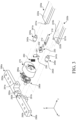
FIG. 3 is an enlarged exploded perspective view of part A inFIG. 2 .FIG. 3 is an exploded perspective view of thehinge assembly 200.FIG. 4A is a perspective view illustrating a structure of a first coupler of the foldable display device according to the embodiment of the present disclosure.FIG. 4B is a perspective view illustrating a structure of a semicircular disc of the foldable display device according to the embodiment of the present disclosure.FIG. 4C is a perspective view illustrating one side portion of a gear housing of the foldable display device according to the embodiment of the present disclosure.FIG. 4D is a perspective view illustrating the other side portion of the gear housing of the foldable display device according to the embodiment of the present disclosure.FIG. 4E is a perspective view illustrating a structure in which constituent elements of the foldable display device according to the embodiment of the present disclosure are coupled in the gear housing. - With reference to
FIGS. 3 to 4E , thehinge assembly 200 according to the embodiment of the present disclosure includes themid bar 210, thefirst flap bar 220a, thesecond flap bar 220b, bendingcouplers 230,first couplers 240a,second couplers 240b,semicircular discs 250,spring members 260,gear housings 270, first rotary gears 280a, second rotary gears 280b, thefirst gear arms 290a, and thesecond gear arms 290b.FIG. 3 illustrates only one of the two hinge assemblies of the present invention, with each hinge assembly being disposed on a respective side of thefoldable display device 100. - With reference to
FIG. 2 , themid bar 210 is disposed between thefirst set housing 110 and thesecond set housing 120. Themid bar 210 can have a flat shape elongated in a longitudinal direction (a Y-axis direction or a second direction). A top surface of themid bar 210 has a flat shape to support thedisplay panel 130. - With reference to
FIGS. 3 , themid bar 210 can be elongated in the Y-axis direction to thegear housing 270 and further protrude than thefirst flap bar 220a and thesecond flap bar 220b. Two opposite side portions of themid bar 210 based on the Y-axis direction can be inserted intosecond accommodation portions 272 formed in thegear housings 270. In this case, a fixinggroove 212 can be formed in a top surface of themid bar 210 inserted into thesecond accommodation portion 272 of thegear housing 270. When themid bar 210 moves upward or downward, thespring member 260 can apply pressure in a Z-axis direction while the fixinggroove 212 suppresses the separation of thespring member 260. - The
mid bar 210 can move upward or downward in a thickness direction (the Z-axis direction or a third direction). Themid bar 210 can move upward or downward to fold or unfold thefirst set housing 110 and thesecond set housing 120. The upward or downward movement of themid bar 210 will be described below with reference to a folding embodiment of the foldable display device according to the embodiment of the present disclosure. - The
first flap bar 220a and thesecond flap bar 220b are disposed at two opposite sides of themid bar 210 based on the width direction (X-axis direction). With reference toFIG. 2 , thefirst flap bar 220a is disposed between themid bar 210 and thefirst set housing 110, and thesecond flap bar 220b is disposed between themid bar 210 and thesecond set housing 120. Thefirst flap bar 220a and thesecond flap bar 220b can each support a part of thedisplay panel 130 and thefirst flap bar 220a and thesecond flap bar 220b can serve as a hinge. Thefirst flap bar 220a and thesecond flap bar 220b can each rotate about a rotation axis defined in the longitudinal direction (Y-axis direction) and each of thefirst flap bar 220a and thesecond flap bar 220b can be positioned at one side adjacent to themid bar 210. - The
first flap bar 220a and thesecond flap bar 220b can each have a blade shape (e.g., a flat bar, a flat or planar rectangular or square shaped bar, etc.). With reference toFIG. 3 , thefirst flap bar 220a and thesecond flap bar 220b can each have a constant thickness and can have an arc shape in which the thickness is reduced at one side portion adjacent to themid bar 210, as shown inFIGs. 5A and 5B , for example. That is, one side portion of thefirst flap bar 220a and one side portion of thesecond flap bar 220b can each have a convexly curved surface. The convexly curved surfaces of thefirst flap bar 220a and thesecond flap bar 220b can face one another when the foldable display device is in an unfolded state, as shown inFIG. 5A . Because one side portion of thefirst flap bar 220a and one side portion of thesecond flap bar 220b each have a curved surface, thefirst flap bar 220a and thesecond flap bar 220b are not affected by themid bar 210 during a process in which the in-folding operation is performed on thefirst flap bar 220a and thesecond flap bar 220b. Further, thefirst flap bar 220a and thesecond flap bar 220b can support thedisplay panel 130 when the out-folding operation is performed. - The other side portion of the
first flap bar 220a and the other side portion of thesecond flap bar 220b can each have various shapes.FIGs. 3 ,5A and 5B illustrate a quadrangular structure in which the other side portion of thefirst flap bar 220a and the other side portion of thesecond flap bar 220b, which are respectively adjacent to thefirst set housing 110 and thesecond set housing 120, each have a rounded edge. However, the present disclosure is not limited thereto. The other side portion of thefirst flap bar 220a and the other side portion of thesecond flap bar 220b can each have an arc shape and have a smaller radius of curvature than each of one side portion of thefirst flap bar 220a and one side portion of thesecond flap bar 220b. Alternatively, the other side portion of thefirst flap bar 220a and the other side portion of thesecond flap bar 220b can each have an edge having a quadrangular or polygonal angled shape or a splined shape. - First protruding
portions first flap bar 220a and one side portion (e.g., a first side portion) of thesecond flap bar 220b adjacent to themid bar 210 in the width direction (X-axis direction). The first protrudingportions gear housing 270 adjacent to the first protrudingportions portions fifth insertion grooves gear housing 270. The first protrudingportions first flap bar 220a and thesecond flap bar 220b. The in-folding state can be made as the other side portion of thefirst flap bar 220a and the other side portion of thesecond flap bar 220b rotate upward about the first protrudingportions first flap bar 220a and the other side portion of thesecond flap bar 220b rotate downward about the first protrudingportions -
First insertion grooves first flap bar 220a and the other side portion (e.g., a second side portion) of thesecond flap bar 220b respectively adjacent to thefirst set housing 110 and thesecond set housing 120. Thefirst insertion grooves first coupler 240a and thesecond coupler 240b adjacent to thefirst insertion grooves first insertion grooves first coupler 240a and thesecond coupler 240b, and are respectively connected to thefirst gear arm 290a and thesecond gear arm 290b, such that thefirst flap bar 220a and thesecond flap bar 220b operates in conjunction with the motions of the first andsecond gear arms first set housing 110 and thesecond set housing 120, the other side portion of thefirst flap bar 220a and the other side portion of thesecond flap bar 220b, which respectively have thefirst insertion grooves first set housing 110 and thesecond set housing 120, the other side portion of thefirst flap bar 220a and the other side portion of thesecond flap bar 220b can rotate downward. - Meanwhile, a
second insertion groove 223b is formed in one side portion of thesecond flap bar 220b adjacent to themid bar 210. Thesecond insertion groove 223b can be connected to the bendingcoupler 230. With reference toFIG. 3 , thesecond insertion groove 223b is formed in an area adjacent to the first protrudingportion 221b of thesecond flap bar 220b. Unlike thefirst insertion grooves gear housing 270, thesecond insertion groove 223b is formed to be concave (e.g., has a concave shape) in the X-axis direction from one side portion of thesecond flap bar 220b adjacent to themid bar 210. In addition, thesecond insertion groove 223b can have an accommodation space formed in thesecond flap bar 220b so that the bendingcoupler 230 is not withdrawn after the bendingcoupler 230 is inserted into thesecond insertion groove 223b. Thesecond insertion groove 223b can have a shape that matches a shape of the bendingcoupler 230, such that when the bendingcoupler 230 is inserted into thesecond insertion groove 223b, it remains fixed (e.g., by a press-fit connection) during a folding and unfolding operation of thefoldable display device 100. That is, thesecond insertion groove 223b has a structure having a narrow inlet and the accommodation space so that the bendingcoupler 230 is not withdrawn when thesecond flap bar 220b rotates. Meanwhile, thesecond insertion groove 223b can have a guide groove so that the bendingcoupler 230 does not restrict the motion of thesecond flap bar 220b when thesecond flap bar 220b rotates. For example, as illustrated inFIG. 3 , thesecond insertion groove 223b has a shape formed by opening a bottom surface of thesecond flap bar 220b, such that the bendingcoupler 230 can move during the folding operation. In addition, a top surface of thesecond insertion groove 223b can have an arc shape so that the bendingcoupler 230 can rotate in thesecond insertion groove 223b. - The
second insertion groove 223b can be formed only in thesecond flap bar 220b without being formed in thefirst flap bar 220a. In the foldable display device according to the embodiment of the present disclosure, only thesecond flap bar 220b of the pair offlap bars coupler 230, such that the bendingcoupler 230 is used to control the rotation of thesemicircular disc 250 and the upward or downward movement of themid bar 210 in accordance with the folding operation of thesecond flap bar 220b. In this case, as described below with reference toFIG. 5B , based on the unfolding state, a central axis of thesecond insertion groove 223b can be formed to be closer to a rotation axis of thesemicircular disc 250 than a central axis of thefirst insertion groove 222a to the rotation axis of thesemicircular disc 250. The motion of thesemicircular disc 250 and the motion of themid bar 210 will be described below with reference to the folding embodiment of the foldable display device according to the embodiment of the present disclosure. - The first and
second couplers second flap bars second gear arms first coupler 240a can connect thefirst flap bar 220a and thesecond gear arm 290b, and thesecond coupler 240b can connect thesecond flap bar 220b and thesecond gear arm 290b. - With reference to
FIGS. 3 and4A together, the first andsecond couplers first connection portions second flap bars first insertion grooves second flap bars second couplers second connection portions second gear arms first fastening grooves second gear arms first connection portions second connection portions first connection portions second connection portions first insertion grooves second flap bars first connection portions first fastening grooves second gear arms second connection portions second gear arms second flap bars second flap bars portions FIG. 5B , during the out-folding operation, thesecond flap bar 220b can be fixed without moving, and a spacing or empty space may not be formed between thedisplay panel 130 and a top surface of thesecond flap bar 220b. That is, in a un-folded state, thesecond flap bar 220b, including its curved surface (e.g., convexly curved surface as described above), directly engages thedisplay panel 130, such that no gap is formed by between thesecond flap bar 220b and thedisplay panel 130. - The bending
coupler 230 is disposed outside themid bar 210 based on the longitudinal direction (Y-axis direction). The bendingcoupler 230 is connected to thesecond flap bar 220b and thesemicircular disc 250. - With reference to
FIG. 3 , the bendingcoupler 230 has a rod shape having a bent middle portion. A bending angle can be about 90°. Therefore, the bendingcoupler 230 can have an "L" shape based on the unfolding state. The bendingcoupler 230 includes a second protrudingportion 231 provided at one side (e.g., a first side) thereof (e.g., facing thefirst flap bar 220a) and connected to thefirst flap bar 220a, and a third protrudingportion 232 provided at the other side (e.g., a second side) thereof (e.g., facing thesecond gear arm 290b) and connected to thesemicircular disc 250. Specifically, the second protrudingportion 231 protrudes in the Y-axis direction and is connected to thesecond insertion groove 223b of thesecond flap bar 220b. The second protrudingportion 231 can have a shape protruding toward two opposite sides in the Y-axis direction so that the second protrudingportion 231 can be seated in the accommodation space formed in thesecond insertion groove 223b. The thirdprotruding portion 232 protrudes in the Y-axis direction in which thegear housing 270 is positioned (e.g., towards thegear housing 270 to which it is connected to). The thirdprotruding portion 232 is inserted into athird insertion groove 251 of thesemicircular disc 250 and cab rotate in thethird insertion groove 251. Thesemicircular disc 250 can include a semicircular portion and a flat portion, and can resemble a disc that is cut in-half. - The bending
coupler 230 controls the rotation of thesemicircular disc 250 in accordance with the rotation of thesecond flap bar 220b. In case that thesecond flap bar 220b is folded about the first protrudingportion 221b that is the rotation axis, the second protrudingportion 231 of the bendingcoupler 230, which is inserted into thesecond insertion groove 223b of thesecond flap bar 220b adjacent to the first protrudingportion 221b, rotates. Therefore, thesemicircular disc 250, which is connected to the third protrudingportion 232 of the bendingcoupler 230, also rotates in accordance with the motion of the bendingcoupler 230. - The
semicircular disc 250 is disposed outside the bendingcoupler 230 based on the longitudinal direction (Y-axis direction). One surface of thesemicircular disc 250 is connected to the bendingcoupler 230, and thesemicircular disc 250 is seated in thegear housing 270 to be described below. - With reference to
FIG. 4B , thesemicircular disc 250 is provided in the form of a plate having a semicircular (e.g., half circle) shape having a predetermined thickness. Thesemicircular disc 250 can be a perfect semicircle made by cutting a circle along any diameter. However, the present disclosure is not limited thereto. Thesemicircular disc 250 can have a shape having a predetermined arc with an obtuse angle. Thesemicircular disc 250 is seated in a third accommodation portion formed in thegear housing 270. - Specifically, the
semicircular disc 250 has thethird insertion groove 251, aflat portion 252, and anarc portion 253. - The
third insertion groove 251 of thesemicircular disc 250 is connected to the third protrudingportion 232 formed at the other side of the bendingcoupler 230. Thethird insertion groove 251 can be formed at a position spaced apart from the rotation axis of thesemicircular disc 250 at a predetermined distance. Thethird insertion groove 251 is connected to the third protrudingportion 232 of the bendingcoupler 230, such that thesemicircular disc 250 can rotate about the rotation axis by a force applied to thethird insertion groove 251 by the movement of the bendingcoupler 230. - The
flat portion 252 is one edge (e.g., one surface) of thesemicircular disc 250 and can have a planar surface. Themid bar 210 can be disposed on theflat portion 252 of thesemicircular disc 250. Specifically, theflat portion 252 supports themid bar 210 and maintains a parallel state of themid bar 210 during the in-folding operation of the foldable display device. - The
arc portion 253 is the remaining edge of thesemicircular disc 250 having a curved arc shape and can have a predetermined radius of curvature. When thesemicircular disc 250 is seated in athird accommodation portion 273 of thegear housing 270, thearc portion 253 of thesemicircular disc 250 corresponds to a side surface of thethird accommodation portion 273. Thethird accommodation portion 273 of thegear housing 270 can have a circular shape having a diameter substantially equal to a diameter of thesemicircular disc 250. In this case, a guide groove, which has a shape recessed inward along the curved surface, can be formed in thearc portion 253. The guide groove formed in thearc portion 253 can be connected to aguide portion 273a having a protruding shape and formed in an inner surface of thethird accommodation portion 273 of thegear housing 270. The guide groove formed in thearc portion 253 and theguide portion 273a of thethird accommodation portion 273 can have concave-convex structures and engage with each other. Therefore, thesemicircular disc 250 can be seated in the third accommodation portion and rotate along theguide portion 273a of thethird accommodation portion 273 by means of the guide groove formed in thearc portion 253. - The
semicircular disc 250 is rotated by the folding operation of thesecond flap bar 220b. In case that thesecond flap bar 220b rotates about the rotation axis of the first protrudingportion 221b, thesemicircular disc 250 is rotated in thethird accommodation portion 273 of thegear housing 270 by the bendingcoupler 230 connected to thesecond flap bar 220b. As thesemicircular disc 250 rotates, themid bar 210 configured to support thesemicircular disc 250 can move upward or downward. In case that themid bar 210 is positioned on thearc portion 253 of thesemicircular disc 250 during the process in which thesemicircular disc 250 rotates, themid bar 210 can be kept raised in the Z-axis direction. In case that themid bar 210 is positioned on theflat portion 252 during the process in which thesemicircular disc 250 rotates, themid bar 210 can move downward (e.g., in the Z-direction). That is, the upward and downward movements of themid bar 210 are implemented by the rotation of thesemicircular disc 250. Specific descriptions related to the motion of thesemicircular disc 250 and the motion of themid bar 210 in the in-folding state, the out-folding state, and the unfolding state will be described below with reference toFIGS. 5A to 5D . - The
gear housing 270 is disposed outside themid bar 210, thefirst flap bar 220a, and thesecond flap bar 220b based on the longitudinal direction (e.g., Y-axis direction). Thegear housing 270 accommodates and protects thefirst rotary gear 280a, thesecond rotary gear 280b, thesemicircular disc 250, and thespring member 260 and accommodates the end of themid bar 210. Thegear housing 270 provides a space in which the respective components can be protected and operated. - With reference to
FIGS. 4C to 4E , thegear housing 270 includes afirst accommodation portion 271, thesecond accommodation portion 272, thethird accommodation portion 273,fourth insertion grooves fifth insertion grooves - The
first accommodation portion 271 is formed at one side of thegear housing 270 adjacent to the first andsecond gear arms fourth insertion grooves first accommodation portion 271 and recieve the first andsecond rotary gear - The
second accommodation portion 272 is formed at one side of thegear housing 270 adjacent to themid bar 210, thefirst flap bar 220a, and thesecond flap bar 220b in the longitudinal direction (e.g., Y-axis direction) to completely accommodate thespring member 260 and accommodate a part of themid bar 210. Thesecond accommodation portion 272 has a shape extending in the thickness direction (e.g., Z-axis direction) so that themid bar 210 inserted into thesecond accommodation portion 272 can move upward or downward. Thesecond accommodation portion 272 has a bottom surface on which themid bar 210 can be supported in the in-folding state. Themid bar 210 and thespring member 260 are sequentially stacked on the bottom surface of thesecond accommodation portion 272. - The
third accommodation portion 273 is formed in thegear housing 270 and disposed at one side of thegear housing 270 at which thesecond accommodation portion 272 is formed. Thethird accommodation portion 273 accommodates thesemicircular disc 250. Thethird accommodation portion 273 has a cylindrical shape corresponding to a diameter and a thickness of thesemicircular disc 250 so that thesemicircular disc 250 can circularly rotate while being accommodated in thethird accommodation portion 273. In particular, thethird accommodation portion 273 can have theguide portion 273a on which thesemicircular disc 250 is seated, and thesemicircular disc 250 is easily rotated circularly. That is, an outer diameter of the third accommodation portion 273 (e.g., theguide portion 273a can be larger than a diameter of the guide portion of thethird accommodation portion 273. As described above, theguide portion 273a of thethird accommodation portion 273 and the guide groove of thearc portion 253 of thesemicircular disc 250 are connected to each other, and thesemicircular disc 250 is seated in the third accommodation portion, such that thesemicircular disc 250 can rotate along theguide portion 273a of thethird accommodation portion 273 by means of the guide groove. That is, theguide portion 273a of thethird accommodation portion 273 can have a smaller diameter than other portions of thethird accommodation portion 273, and further, theguide portion 273a can engage the groove of the arc portion 253a of thesemicircular disc 250. - Meanwhile, the
third accommodation portion 273 is formed to connected to thesecond accommodation portion 272. With respect toFIG. 4D , an upper portion of thethird accommodation portion 273 having a cylindrical shape is connected to and overlaps thesecond accommodation portion 272. Therefore, a stepped portion is formed between thethird accommodation portion 273 and thesecond accommodation portion 272. That is, thethird accommodation portion 273 having a cylindrical shape is formed first in the Y-axis direction from one side of thegear housing 270, and then thesecond accommodation portion 272 having a rectangular parallelepiped shape is connected to thethird accommodation portion 273. The stepped portion between thethird accommodation portion 273 and thesecond accommodation portion 272 can be formed to correspond to theflat portion 252 of thesemicircular disc 250 when thesemicircular disc 250 is seated in thethird accommodation portion 273 and theflat portion 252 is positioned upward. - The
spring member 260 is disposed in thesecond accommodation portion 272 of thegear housing 270 and disposed in the fixinggroove 212 formed in the top surface of themid bar 210. Thespring member 260 transmits downward pressure to themid bar 210. In case that themid bar 210 is moved upward by the rotation of thesemicircular disc 250, thespring member 260 transmits pressure so that themid bar 210 can be restored to an original position. - With reference to
FIG. 3 , thefirst rotary gear 280a and thesecond rotary gear 280b are disposed in thefirst accommodation portion 271 of thegear housing 270. Thefirst rotary gear 280a and thesecond rotary gear 280b can be completely accommodated in thegear housing 270. Thefirst rotary gear 280a and thesecond rotary gear 280b serve as rotary shafts that rotate the first andsecond gear arms second set housings FIG. 3 , an edge portion (e.g., edge portion in the lateral direction) of each of the first and second rotary gears 280a and 280b can have a circular cross-section, and a central portion (e.g., central lateral portion in the Y-direction) of each of the first and second rotary gears 280a and 280b can have teeth. Thefirst rotary gear 280a and thesecond rotary gear 280b can be disposed to engage (e.g., mesh) with each other. One side of thefirst rotary gear 280a and one side of thesecond rotary gear 280b are respectively connected to thefourth insertion grooves first accommodation portion 271. The other side of thefirst rotary gear 280a and the other side of thesecond rotary gear 280b are respectively connected tosecond fastening grooves second gear arms FIG. 3 illustrates that the two rotary gears are configured as two-axis gears. However, the present disclosure is not limited thereto. For example, four rotary gears can be provided as four-axis gears. - The
first gear arm 290a and thesecond gear arm 290b are disposed outside thefirst rotary gear 280a and thesecond rotary gear 280b based on the longitudinal direction (e.g., Y-axis direction). The first andsecond gear arms hinge assembly 200 and the first andsecond set housings second set housings hinge assembly 200. - With reference to
FIG. 3 , the first andsecond gear arms first fastening grooves second couplers second fastening grooves third fastening grooves second set housings - The
first fastening grooves second gear arms second flap bars second couplers first flap bar 220a and the other side portion of thesecond flap bar 220b can be rotated by the motions of the first andsecond gear arms - When the
first rotary gear 280a and thesecond rotary gear 280b rotate about the pair of rotation axes, thefirst gear arm 290a and thesecond gear arm 290b can rotate together with thefirst rotary gear 280a and thesecond rotary gear 280b. In this case, the centers of thesecond fastening grooves second gear arms - In addition, the
third fastening grooves second gear arms first fastening part 116 of thefirst set housing 110 and thesecond fastening part 126 of thesecond set housing 120, such that the set housings and the other constituent elements accommodated in the set housings can be folded or unfolded on the basis of whether thehinge assembly 200 operates. - Hereinafter, the structures and operations of the main constituent elements of the hinge assembly at the time of folding or unfolding the
foldable display device 100 will be described in detail with reference toFIGS. 5A to 5C . -
FIG. 5A is a cross-sectional view taken along line I-I' inFIG. 2 and illustrating the unfolding state of the foldable display device according to the embodiment of the present disclosure.FIG. 5B is a schematic cross-sectional view illustrating the out-folding state of the foldable display device according to the embodiment of the present disclosure.FIG. 5C is a schematic cross-sectional view illustrating the in-folding state of the foldable display device according to the embodiment of the present disclosure.FIG. 5D is a schematic cross-sectional view illustrating a shape of the display panel in the in-folding state of the foldable display device according to the embodiment of the present disclosure. -
FIG. 5A illustrates that the foldable display device is in the unfolding state, i.e., the first and second set housings are completely unfolded at an angle of 180°. - With reference to
FIG. 5A , the first and second set housings are completely unfolded at an angle of 180°. Therefore, the first andsecond gear arms second flap bars second couplers second gear arms coupler 230 connected to one side portion of thesecond flap bar 220b allows thesemicircular disc 250 to be positioned at the right side in the third accommodation portion of thegear housing 270. As illustrated inFIG. 5A , as thearc portion 253 of thesemicircular disc 250 is positioned at the right side, one end of thearc portion 253 is positioned at the upper side based on the Z-axis direction, and thearc portion 253 of thesemicircular disc 250 is positioned at the lower side of themid bar 210 and supports themid bar 210. That is, themid bar 210 is supported upward by thearc portion 253 of thesemicircular disc 250 positioned at the lower side, such that themid bar 210 is disposed on the same plane as the first andsecond flap bars mid bar 210. Therefore, themid bar 210 and the first andsecond flap bars display panel 130 positioned on the first andsecond support bodies mid bar 210, and the first andsecond flap bars -
FIG. 5B illustrates that the foldable display device is in the out-folding state, e.g., the first and second set housings are completely folded rearward so that the display panel is disposed outward. - With reference to
FIG. 5B , the first and second set housings are each folded downward at about 90° based on the unfolding state illustrated inFIG. 5A so that thedisplay panel 130 is disposed outward. As illustrated inFIG. 5B , the first andsecond gear arms second flap bars second couplers second gear arms second flap bar 220b is folded downward about the first protrudingportion 221b as the rotation axis, the bendingcoupler 230 connected to one side portion of thesecond flap bar 220b moves to the right side. The second protrudingportion 231 of the bendingcoupler 230 connected to one side portion of thesecond flap bar 220b is positioned to be closer to the rotation axis of thesemicircular disc 250 than the first protrudingportion 221b to the rotation axis of thesemicircular disc 250. Therefore, in case that thesecond flap bar 220b is folded downward about the first protrudingportion 221b as the rotation axis, the bendingcoupler 230 provides a force to the right side by means of the motion of thesecond flap bar 220b, and thesemicircular disc 250, which receives the force from the bendingcoupler 230, rotates counterclockwise. Therefore, thesemicircular disc 250 is positioned at the upper side in the third accommodation portion of thegear housing 270. As illustrated inFIG. 5B , a part of thearc portion 253 is still positioned below themid bar 210 even though thearc portion 253 of thesemicircular disc 250 rotates. Therefore, thearc portion 253 of thesemicircular disc 250 consistently supports themid bar 210. Therefore, even though thesemicircular disc 250 rotates, themid bar 210 is continuously supported upward by thearc portion 253 of thesemicircular disc 250 positioned below themid bar 210, such that themid bar 210 is kept in place without being moved upward or downward by elasticity of thespring member 260. In this case, the first andsecond flap bars display panel 130 performs the out-folding operation in the downward direction at about 90° along the curved surface of one side portion of thefirst flap bar 220a and the curved surface of one side portion of thesecond flap bar 220b from the top surface of themid bar 210. - In this case, the
display panel 130 in the folding area is still supported in the central portion of the folding area by themid bar 210, thedisplay panel 130 can be inhibited from being pushed by external impact and pressure during the out-folding operation. In addition, with reference toFIG. 5B , one side portion of thefirst flap bar 220a and one side portion of thesecond flap bar 220b, which are adjacent to themid bar 210, each have a curved shape C. The two opposite sides of each of the first andsecond flap bars second flap bars display panel 130, which is disposed along the top surfaces of themid bar 210 and the first andsecond flap bars display panel 130 is in contact with the first andsecond flap bars display panel 130 to reduce the occurrence of cracks and/or creases during the out-folding operation. - Meanwhile, as described above, during the out-folding operation, one side portion of each of the
flap bars flap bars Expression 1 below. In addition, in case that one side portion of each of theflap bars Expression 1 below. During the out-folding operation, the stress concentrated on the display panel can vary depending on a size of the edge being in direct contact with thedisplay panel 130.
- In case that the length H in the lateral direction of the length V in the upward direction of the
flap bar Expression 1 based on the shape during the out-folding operation, the stress applied to the display panel during the out-folding operation can generally decrease. As a result, the performance of the display panel maintained for a long period of time. - Meanwhile, in the foldable display device according to the embodiment of the present disclosure, a parallelogrammatic shape is defined by a first center point of one side portion of the second flap bar at which the second flap bar and the gear housing are connected, a second center point of the second insertion groove at which the second flap bar and the bending coupler are connected, a third center point of the second connection portion at which the second flap bar and the first connection portion of the second coupler are connected, and a fourth center point of the second connection portion at which the second gear arm and the second connection portion of the second coupler are connected.
- In other words, based on the
second flap bar 220b connected to the bendingcoupler 230 during the out-folding operation, the foldable display device according to the embodiment of the present disclosure, has the parallelogrammatic shape in which a first point, at which the first protrudingportion 221b of thesecond flap bar 220b and thefifth insertion groove 275b of thegear housing 270 are connected, a second point, at which thesecond insertion groove 223b of thesecond flap bar 220b and the second protrudingportion 231 of the bendingcoupler 230 are connected, a third point, at which thefirst insertion groove 222b of thesecond flap bar 220b and thefirst connection portion 241b of thesecond coupler 240b are connected, and a fourth point, at which thesecond connection portion 242b of thesecond coupler 240b and thefirst fastening groove 291b of thesecond gear arm 290b are connected, are always constant. Therefore, the folding angle of thesecond gear arm 290b and the folding angle of thesecond flap bar 220b can be always equally maintained. Therefore, during the out-folding operation, thesecond flap bar 220b is fixed without moving, and a spacing or empty space is not formed between thedisplay panel 130 and the top surface of thesecond flap bar 220b. Therefore, the durability against external impact and pressure during the out-folding operation can be significantly improved. -
FIG. 5C illustrates that the foldable display device is in the in-folding state, i.e., the first and second set housings are completely folded so that the display panel is disposed inward. - With reference to
FIG. 5C , the first and second set housings are each folded upward at about 90° based on the unfolding state illustrated inFIG. 5A so that thedisplay panel 130 is disposed inward. As illustrated inFIG. 5C , the first andsecond gear arms second flap bars second couplers second gear arms second flap bar 220b is folded upward about the first protrudingportion 221b as the rotation axis, the bendingcoupler 230 connected to one side portion of thesecond flap bar 220b moves to the left side. Specifically, the second protrudingportion 231 of the bendingcoupler 230 connected to one side portion of thesecond flap bar 220b is positioned to be closer to the rotation axis of thesemicircular disc 250 than the first protrudingportion 221b to the rotation axis of thesemicircular disc 250. Therefore, in case that thesecond flap bar 220b is folded upward about the first protrudingportion 221b as the rotation axis, the bendingcoupler 230 provides a force to the left side by means of the motion of thesecond flap bar 220b, and thesemicircular disc 250, which receives the force from the bendingcoupler 230, rotates clockwise. Therefore, thesemicircular disc 250 is positioned at the lower side in the third accommodation portion of thegear housing 270. As illustrated inFIG. 5C , as thesemicircular disc 250 rotates clockwise, thearc portion 253 of thesemicircular disc 250, which supports themid bar 210, is positioned to be directed downward, and theflat portion 252 of thesemicircular disc 250 is positioned to be directed upward. As thearc portion 253 of thesemicircular disc 250, which supports themid bar 210, is directed downward, themid bar 210 is moved downward by elasticity (e.g., elastic force) of thespring member 260. Therefore, themid bar 210 is supported by the bottom surface of the second accommodation portion of thegear housing 270 or theflat portion 252 of thesemicircular disc 250 and positioned at the lower side in comparison withFIGS. 5A and 5B . In this case, the first andsecond flap bars - With reference to
FIG. 5D , themid bar 210 is positioned at the lower side in the state in which the foldable display device is in the in-folding state. Therefore, thefirst support body 112, thesecond support body 122, themid bar 210, and the first andsecond flap bars display panel 130 can be disposed in an omega (Ω) shape. In case that thedisplay panel 130 is folded in an omega (Ω) shape, a radius of curvature can increase, such that the stress applied to the foldeddisplay panel 130 can be reduced. - Meanwhile, with reference to
FIG. 5D , in the in-folding state, an interval d1 between a first contact point P1, at which thefirst flap bar 220a and thedisplay panel 130 are in contact with each other, a second contact point P2, at which thesecond flap bar 220b and thedisplay panel 130 are in contact with each other, i.e., an interval d1 between the top surface of thefirst flap bar 220a and the top surface of thesecond flap bar 220b can be 3.5 mm to 4.5 mm or 3.8 mm to 4.2 mm. In this case, to fold thedisplay panel 130 in an omega (Ω) shape, a distance between the top surface of thefirst support body 112 and the top surface of thesecond support body 122 can be 1.8 mm to 2.2 mm. Meanwhile, with reference toFIG. 5B , in the out-folding state, a distance d2 between the top surface of thefirst flap bar 220a and the top surface of thesecond flap bar 220b can be 11 mm to 13 mm or 11.5 mm to 12.5 mm. In this case, the stress applied to thedisplay panel 130 having the omega (Ω) shape can be reduced. - In case that a size of the omega (Ω) shape of the
display panel 130 in the in-folding state is reduced by adjusting the interval between the first andsecond flap bars display panel 130 in the in-folding state can be reduced at the point at which thedisplay panel 130 comes into contact with the first andsecond flap bars FIG. 5B , during the out-folding operation in which the first andsecond flap bars display panel 130 is disposed outward, the first andsecond flap bars first flap bar 220a and one side portion of thesecond flap bar 220b are each maintained to have the curved shape C instead of an angled shape. In this case, thedisplay panel 130 performs the out-folding operation downward along the curved shape C defined by the first andsecond flap bars display panel 130 is in direct contact with the curved shape C formed by one side portion of thefirst flap bar 220a and one side portion of thesecond flap bar 220b and folded at a great angle on this point, such that a large amount of stress is concentrated on the portions where thedisplay panel 130 and the first andsecond flap bars display panel 130 and the first andsecond flap bars display panel 130. - Therefore, it can be ascertained that in a foldable display device according to another embodiment of the present disclosure, in case that the interval d1 between the top surface of the
first flap bar 220a and the top surface of thesecond flap bar 220b in the in-folding state and the distance d2 between the top surface of thefirst flap bar 220a and the top surface of thesecond flap bar 220b in the out-folding state satisfy the above-mentioned numerical value range, the compressive strain applied, during the in-folding operation, to the portions where thedisplay panel 130 and the first andsecond flap bars - The exemplary embodiments of the present disclosure can also be described as follows:
According to an aspect of the present disclosure, there is provided a foldable display device. The foldable display device comprises a display panel, a first set housing and a second set housing disposed to face each other in a first direction and respectively supporting two different portions of the display panel, and a hinge assembly disposed between the first set housing and the second set housings and configured to fold and unfold the first set housing and the second set housing. The hinge assembly comprises a mid bar disposed between the first set housing and the second set housing and having a shape extending in a second direction perpendicular to the first direction, a first flap bar disposed between the first set housing and the mid bar, a second flap bar disposed between the second set housing and the mid bar, a bending coupler having a bent rod shape and having one side connected to the second flap bar, a semicircular disc connected to the other side of the bending coupler and including a flat portion having a planar surface, and an arc portion having a curved arc surface, the semicircular disc being configured to rotate about a central axis, a gear housing configured to accommodate the semicircular disc and accommodate an end of the mid bar, a spring member disposed at the end of the mid bar and accommodated in the gear housing, a first coupler and a second coupler respectively including first connection portions protruding toward the first flap bar and a second flap bar in the second direction, and second connection portions protruding in a direction opposite to the direction of the first connection portions in the second direction, and a first gear arm and a second gear arm coupled respectively with the second connection portion of the first coupler and the second connection portion of the second coupler. - Each of the first set housing and the second set housing can comprise a support body disposed below the display panel, a frame disposed at an edge of the support body, and a fastening part provided on the frame. The fastening part of the first set housing can be fastened to the first gear arm, and the fastening part of the second set housing can be fastened to the second gear arm.
- One side portion of each of the first flap bar and the second flap bar adjacent to the mid bar can be connected to the gear housing, the other side portion of the first flap bar adjacent to the first set housing can be connected to the first connection portion of the first coupler, and the other side portion of the second flap bar adjacent to the second set housing can be connected to the first connection portion of the second coupler.
- The other side portion of each of the first flap bar and the second flap bar can rotate about one side portion of each of the first flap bar and the second flap bar as a rotation axis.
- The second flap bar can have a second insertion groove formed to be concave in the first direction in one side portion of the second flap bar adjacent to the mid bar so that the second insertion groove is connected to a protruding portion formed at one side of the bending coupler, and one side of the bending coupler can rotate about the second insertion groove as a central axis.
- A central axis of the first connection portion and a central axis of the second connection portion can be different from each other, and a rotation axis of one side portion of the second flap bar can be different from a central axis of the second insertion groove.
- The foldable display device can further comprise a first rotary gear and a second rotary gear respectively coupled to the first gear arm and the second gear arm. The gear housing can comprise a first accommodation portion formed to be directed toward the first gear arm and the second gear arm and configured to accommodate the first rotary gear and the second rotary gear, a second accommodation portion formed to be directed toward the first flap bar and the second flap bar and configured to accommodate the spring member and the end of the mid bar, and a third accommodation portion formed to be directed toward the first flap bar and the second flap bar and configured to accommodate the semicircular disc. The second accommodation portion and the third accommodation portion can be connected to each other.
- The second accommodation portion can have a shape extending in a thickness direction so that the mid bar moves upward or downward. The third accommodation portion can have a cylindrical shape having a predetermined diameter so that the semicircular disc circularly rotates. A stepped portion can be formed between the second accommodation portion and the third accommodation portion so that the mid bar is supported on a bottom surface of the second accommodation portion.
- The semicircular disc can further comprise a third insertion groove configured to be connected to a protruding portion formed at the other side of the bending coupler. The arc portion can be disposed to correspond to an inner surface of the third accommodation portion.
- The arc portion of the semicircular disc can have a guide groove having a shape recessed inward along a curved surface. A guide portion can be formed on the inner surface of the third accommodation portion and have a shape protruding along the inner surface of the third accommodation portion so that the guide connected is connected to the guide groove.
- In an unfolding state in which the display panel is disposed flat, the semicircular disc can be positioned such that the arc portion is adjacent to the first flap bar, and the mid bar can be disposed to be in contact with a part of the arc portion of the semicircular disc.
- During an out-folding operation in which the display panel is disposed outward, the semicircular disc can be positioned such that the arc portion is adjacent to the mid bar and the flat portion is directed in an out-folding direction. The mid bar can be disposed to be in contact with a part of the arc portion of the semicircular disc.
- During an in-folding operation in which the display panel is disposed inward, the semicircular disc can be positioned such that the flat portion is directed in an in-folding direction. The mid bar can be disposed to be in contact with a part of the flat portion of the semicircular disc by the spring member.
- In an in-folding state in which the display panel is disposed inward, the display panel can have an omega (Ω) shape.
- A parallelogrammatic shape can be defined in which a first center point of one side portion of the second flap bar, at which the second flap bar and the gear housing are connected, a second center point of the second insertion groove, at which the second flap bar and the bending coupler are connected, a third center point of the first connection portion, at which the second flap bar and the first connection portion of the second coupler are connected, and a fourth center point of the second connection portion, at which the second gear arm and the second connection portion of the second coupler are connected, are always constant.
- During an out-folding operation in which the display panel is disposed outward, the parallelogrammatic shape defined by the first center point, the second center point, the third center point, and the fourth center point can be constantly maintained.
- Various embodiments described herein may be implemented in a computer-readable medium using, for example, software, hardware, or some combination thereof. For example, the embodiments described herein may be implemented within one or more of Application Specific Integrated Circuits (ASICs), Digital Signal Processors (DSPs), Digital Signal Processing Devices (DSPDs), Programmable Logic Devices (PLDs), Field Programmable Gate Arrays (FPGAs), processors, controllers, micro-controllers, microprocessors, other electronic units designed to perform the functions described herein, or a selective combination thereof. In some cases, such embodiments are implemented by the controller. That is, the controller is a hardware-embedded processor executing the appropriate algorithms (e.g., flowcharts) for performing the described functions and thus has sufficient structure. Also, the embodiments such as procedures and functions may be implemented together with separate software modules each of which performs at least one of functions and operations. The software codes can be implemented with a software application written in any suitable programming language. Also, the software codes can be stored in the memory and executed by the controller, thus making the controller a type of special purpose controller specifically configured to carry out the described functions and algorithms. Thus, the components shown in the drawings have sufficient structure to implement the appropriate algorithms for performing the described functions.
- Although the exemplary embodiments of the present disclosure have been described in detail with reference to the accompanying drawings, the present disclosure is not limited thereto and can be embodied in many different forms without departing from the technical concept of the present disclosure. Therefore, the exemplary embodiments of the present disclosure are provided for illustrative purposes only but not intended to limit the technical concept of the present disclosure. The scope of the technical concept of the present disclosure is not limited thereto. Therefore, it should be understood that the above-described exemplary embodiments are illustrative in all aspects and do not limit the present disclosure. The protective scope of the present disclosure should be construed based on the following claims, and all the technical concepts in the equivalent scope thereof should be construed as falling within the scope of the present disclosure.
- The disclosure comprises the following items:
- 1. A foldable display device comprising:
- a display panel;
- a first set housing and a second set housing facing each other in a first direction and respectively supporting two different portions of the display panel; and
- a hinge assembly connected between the first set housing and the second set housing, the hinge assembly being configured to fold and unfold the first set housing and the second set housing,
- wherein the hinge assembly comprises:
- a mid bar disposed between the first set housing and the second set housing and having a shape extending in a second direction perpendicular to the first direction;
- a first flap bar disposed between the first set housing and the mid bar;
- a second flap bar disposed between the second set housing and the mid bar;
- a bending coupler having a bent rod shape and having a first side connected to the second flap bar;
- a semicircular disc connected to a second side of the bending coupler, the semicircular disc including:
- a flat portion having a planar surface; and
- an arc portion having a curved arc surface, the semicircular disc being configured to rotate about a central axis;
- a gear housing configured to accommodate the semicircular disc and accommodate an end of the mid bar;
- a spring member disposed at the end of the mid bar and accommodated in the gear housing;
- a first coupler including a first connection portion protruding toward the first flap bar and a second connection portion opposite to the first connection portion;
- a second coupler including a first connection portion protruding toward the second flap bar and a second connection portion opposite to the first connection portion;
- a first gear arm coupled with the second connection portion of the first coupler; and
- a second gear arm coupled with the second connection portion of the second coupler.
- 2. The foldable display device of
item 1, wherein each of the first set housing and the second set housing comprises:- a support body disposed below the display panel;
- a frame disposed at an edge of the support body; and
- a fastening part provided on the frame, and
- wherein the fastening part of the first set housing is fastened to the first gear arm, and the fastening part of the second set housing is fastened to the second gear arm.
- 3. The foldable display device of
item 1 or item 2, wherein a first side portion of each of the first flap bar and the second flap bar adjacent to the mid bar is connected to the gear housing,- wherein a second side portion of the first flap bar adjacent to the first set housing is connected to the first connection portion of the first coupler, and
- wherein a second side portion of the second flap bar adjacent to the second set housing is connected to the first connection portion of the second coupler.
- 4. The foldable display device of any preceding item, wherein the second side portion of the first flap bar and the second flap bar rotate about the first side portion of the first flap bar and the second flap bar as a rotation axis, respectively.
- 5. The foldable display device of any preceding item, wherein the second flap bar includes a second insertion groove having a concave shape in the first direction in the first side portion of the second flap bar adjacent to the mid bar so that the second insertion groove is connected to a protruding portion formed at a first side of the bending coupler, and
wherein the first side of the bending coupler rotates about the second insertion groove as a central axis. - 6. The foldable display device of any preceding item, wherein a central axis of the first connection portion and a central axis of the second connection portion are different from each other, and
wherein a rotation axis of the first side portion of the second flap bar is different from a central axis of the second insertion groove. - 7. The foldable display device of any preceding item, further comprising:
- a first rotary gear and a second rotary gear respectively coupled to the first gear arm and the second gear arm,
- wherein the gear housing comprises:
- a first accommodation portion accommodating the first rotary gear and the second rotary gear;
- a second accommodation portion accommodating the spring member and the end of the mid bar; and
- a third accommodation portion formed accommodating the semicircular disc, and
- wherein the second accommodation portion and the third accommodation portion are connected to each other.
- 8. The foldable display device of any preceding item, wherein the second accommodation portion has a shape extending in a thickness direction to allow the mid bar to move upwards and downwards,
- wherein the third accommodation portion has a cylindrical shape having a predetermined diameter so that the semicircular disc circularly rotates, and
- wherein a stepped portion is formed between the second accommodation portion and the third accommodation portion so that the mid bar is supported on a bottom surface of the second accommodation portion.
- 9. The foldable display device of any preceding item, wherein the semicircular disc further comprises a third insertion groove configured to be connected to a protruding portion formed at a second side of the bending coupler.
- 10. The foldable display device of any preceding item, wherein the arc portion of the semicircular disc has a guide groove recessed inward along a curved surface, and
wherein a guide portion is formed on the inner surface of the third accommodation portion, the guide portion protruding along the inner surface of the third accommodation portion so that the guide portion is connected to the guide groove. - 11. The foldable display device of any preceding item, wherein in an unfolding state in which the display panel is flat, the semicircular disc is positioned such that the arc portion is adjacent to the first flap bar, and the mid bar is in contact with a part of the arc portion.
- 12. The foldable display device of any preceding item, wherein during an out-folding operation in which the display panel faces outward, the semicircular disc is positioned such that the arc portion is adjacent to the mid bar, the flat portion is directed in an out-folding direction, and the mid bar is in contact with a part of the arc portion.
- 13. The foldable display device of any preceding item, wherein during an in-folding operation in which the display panel faces inward, the semicircular disc is positioned such that the flat portion is directed in an in-folding direction, and the mid bar is in contact with a part of the flat portion of the semicircular disc by the spring member.
- 14. The foldable display device of any preceding item, wherein in an in-folding state in which the display panel faces inward, the display panel has an omega (Ω) shape.
- 15. The foldable display device of any preceding item, wherein a first center point of one side portion of the second flap bar, at which the second flap bar and the gear housing are connected, a second center point of the second insertion groove, at which the second flap bar and the bending coupler are connected, a third center point of the first connection portion, at which the second flap bar and the first connection portion of the second coupler are connected, and a fourth center point of the second connection portion, at which the second gear arm and the second connection portion of the second coupler are connected, are always constant.
- 16. The foldable display device of any preceding item, wherein during an out-folding operation in which the display panel faces outward, a parallelogrammatic shape defined by the first center point, the second center point, the third center point, and the fourth center point is constantly maintained.
- 17. A foldable display device comprising:
- a display panel;
- a first set housing supporting a first portion of the display panel;
- a second set housing supporting a second portion of the display panel; and
- a hinge assembly connected between the first set housing and the second set housing, the hinge assembly being configured to fold and unfold the first set housing and the second set housing,
- wherein the hinge assembly comprises:
- a first gear arm including:
- a first fastening groove;
- a second fastening groove; and
- third fastening grooves connected to the first set housing;
- a second gear arm including:
- a first fastening groove;
- a second fastening groove; and
- third fastening grooves connected to the second set housing;
- a first rotary gear connected to the second fastening groove of the first gear arm;
- a second rotary gear connected to the second fastening groove of the second gear arm, the second rotary gear meshing with the first rotary gear;
- a first flap bar connected to the first fastening groove of the first gear arm; and
- a second flap bar connected to the first fastening groove of the second gear arm.
- a first gear arm including:
- 18. The foldable display device of item 17, further comprising:
- a first coupler including:
- a first connection portion coupled to a first coupling groove of the first flap bar; and
- a second connection portion coupled to the first fastening groove of the first gear arm; and
- a second coupler including:
- a first connection portion coupled to a first coupling groove of the second flap bar; and
- a second connection portion coupled to the first fastening groove of the second gear arm.
- a first coupler including:
- 19. The foldable display device of item 17 or item 18, further comprising:
- a gear housing including:
fourth insertion grooves respectively fixed to the first and second rotary gears; and - fifth insertion grooves respectively fixed to protruding portions of the first and second flap bars.
- a gear housing including:
- 20. The foldable display device of any of items 17-19, further comprising:
- a semicircular disc accommodated in the gear housing and configured to rotate inside of the gear housing; and
- a mid bar disposed between the first flap bar and the second flap bar and accommodated in the gear housing, the mid bar being configured to move in response to a folding and an unfolding operation of the foldable display device.
Claims (15)
- A foldable display device comprising:a display panel;a first set housing and a second set housing adjacent to each other in a first direction and respectively supporting two different portions of the display panel; anda hinge assembly connected between the first set housing and the second set housing, the hinge assembly being configured to fold and unfold the foldable display device,wherein the hinge assembly comprises:a mid bar disposed between the first set housing and the second set housing and having a shape extending in a second direction perpendicular to the first direction;a first flap bar disposed between the first set housing and the mid bar;a second flap bar disposed between the second set housing and the mid bar;a bending coupler having a bent rod shape and having a first side connected to the second flap bar;a semicircular disc connected to a second side of the bending coupler, the semicircular disc including:a flat portion having a planar surface; andan arc portion having a curved arc surface, the semicircular disc being configured to rotate about a rotation axis;a gear housing configured to accommodate the semicircular disc and accommodate an end of the mid bar;a spring member disposed at the end of the mid bar and accommodated in the gear housing;a first coupler including a first connection portion protruding toward the first flap bar and a second connection portion opposite to the first connection portion;a second coupler including a first connection portion protruding toward the second flap bar and a second connection portion opposite to the first connection portion;a first gear arm coupled with the second connection portion of the first coupler; anda second gear arm coupled with the second connection portion of the second coupler.
- The foldable display device of claim 1, wherein each of the first set housing and the second set housing comprises a respective instance of:a support body disposed below the display panel;a frame disposed at an edge of the support body; anda fastening part provided on the frame, andwherein the fastening part of the first set housing is fastened to the first gear arm, and the fastening part of the second set housing is fastened to the second gear arm.
- The foldable display device of claim 1 or claim 2, wherein a respective first side portion of each of the first flap bar and the second flap bar adjacent to the mid bar is connected to the gear housing,wherein a second side portion of the first flap bar adjacent to the first set housing is connected to the first connection portion of the first coupler, andwherein a second side portion of the second flap bar adjacent to the second set housing is connected to the first connection portion of the second coupler.
- The foldable display device of claim 3, wherein the second side portion of the first flap bar is configured to rotate about a rotation axis coinciding with the first side portion of the first flap bar, and the second side portion of the second flap bar is configured to rotate around a rotation axis coinciding with the first side portion of the second flap bar.
- The foldable display device of claim 4, wherein the second flap bar includes a second insertion groove having a concave shape in the first direction in the first side portion of the second flap bar adjacent to the mid bar so that the second insertion groove is connected to a protruding portion formed at a first side of the bending coupler, and
wherein the first side of the bending coupler is configured to rotate about an axis defined within the second insertion groove. - The foldable display device of claim 5, wherein a central axis of the first connection portion and a central axis of the second connection portion are different from each other, and
wherein the rotation axis coinciding with the first side portion of the second flap bar is different from the axis defined within the second insertion groove. - The foldable display device of any preceding claim, further comprising:a first rotary gear and a second rotary gear respectively coupled to the first gear arm and the second gear arm,wherein the gear housing comprises:a first accommodation portion accommodating the first rotary gear and the second rotary gear;a second accommodation portion accommodating the spring member and the end of the mid bar; anda third accommodation portion formed accommodating the semicircular disc, andwherein the second accommodation portion and the third accommodation portion are connected to each other.
- The foldable display device of claim 7, wherein the second accommodation portion has a shape extending in a thickness direction to allow the mid bar to move upwards and downwards,wherein the third accommodation portion has a cylindrical shape having a predetermined diameter so that the semicircular disc is enabled to circularly rotate, andwherein a stepped portion is formed between the second accommodation portion and the third accommodation portion so that the mid bar is supported on a bottom surface of the second accommodation portion.
- The foldable display device of claim 8, wherein the semicircular disc further comprises a third insertion groove configured to be connected to a protruding portion formed at a second side of the bending coupler.
- The foldable display device of claim 9, wherein the arc portion of the semicircular disc has a guide groove recessed inward along the curved arc surface, and
wherein a guide portion is formed on the inner surface of the third accommodation portion, the guide portion protruding along the inner surface of the third accommodation portion so that the guide portion is connected to the guide groove. - The foldable display device of any preceding claim, wherein in an unfolding state in which the display panel is flat, the semicircular disc is positioned such that the arc portion is adjacent to the first flap bar, and the mid bar is in contact with a part of the arc portion.
- The foldable display device of any preceding claim, wherein during an out-folding operation in which the display panel faces outward, the semicircular disc is positioned such that the arc portion is adjacent to the mid bar, the flat portion is directed in an out-folding direction, and the mid bar is in contact with a part of the arc portion.
- The foldable display device of any preceding claim, wherein during an in-folding operation in which the display panel faces inward, the semicircular disc is positioned such that the flat portion is directed in an in-folding direction, and the mid bar is in contact with a part of the flat portion of the semicircular disc by the spring member.
- The foldable display device of any preceding claim, wherein in an in-folding state in which the display panel faces inward, the display panel has an omega (Ω) shape.
- The foldable display device of claim 6, wherein a first center point of one side portion of the second flap bar, at which the second flap bar and the gear housing are connected, a second center point of the second insertion groove, at which the second flap bar and the bending coupler are connected, a third center point of the first connection portion, at which the second flap bar and the first connection portion of the second coupler are connected, and a fourth center point of the second connection portion, at which the second gear arm and the second connection portion of the second coupler are connected, are always constant, and optionally wherein during an out-folding operation in which the display panel faces outward, a parallelogrammatic shape defined by the first center point, the second center point, the third center point, and the fourth center point is constantly maintained.
Applications Claiming Priority (1)
| Application Number | Priority Date | Filing Date | Title |
|---|---|---|---|
| KR1020220190083A KR20240107440A (en) | 2022-12-30 | 2022-12-30 | Foldable display apparatus |
Publications (2)
| Publication Number | Publication Date |
|---|---|
| EP4394550A1 true EP4394550A1 (en) | 2024-07-03 |
| EP4394550B1 EP4394550B1 (en) | 2025-10-29 |
Family
ID=89224360
Family Applications (1)
| Application Number | Title | Priority Date | Filing Date |
|---|---|---|---|
| EP23218617.1A Active EP4394550B1 (en) | 2022-12-30 | 2023-12-20 | Foldable display device |
Country Status (4)
| Country | Link |
|---|---|
| US (1) | US12490395B2 (en) |
| EP (1) | EP4394550B1 (en) |
| KR (1) | KR20240107440A (en) |
| CN (1) | CN118274022A (en) |
Citations (1)
| Publication number | Priority date | Publication date | Assignee | Title |
|---|---|---|---|---|
| US20210096596A1 (en) * | 2018-07-13 | 2021-04-01 | Guangdong Oppo Mobile Telecommunications Corp., Ltd. | Foldable Electronic Device |
Family Cites Families (6)
| Publication number | Priority date | Publication date | Assignee | Title |
|---|---|---|---|---|
| US8804349B2 (en) * | 2012-10-19 | 2014-08-12 | Samsung Display Co., Ltd. | Foldable display device |
| TWM601952U (en) * | 2019-09-10 | 2020-09-21 | 信錦企業股份有限公司 | Quick release structure |
| KR102668216B1 (en) * | 2019-12-02 | 2024-05-23 | 삼성전자주식회사 | Foldable electronic device including hinge assembly |
| CN214413192U (en) * | 2020-02-20 | 2021-10-15 | 信锦企业股份有限公司 | foldable electronic device |
| TWI747708B (en) * | 2021-01-12 | 2021-11-21 | 富世達股份有限公司 | Two-axis synchronous hinge |
| US12396112B2 (en) * | 2021-12-31 | 2025-08-19 | Lg Display Co., Ltd. | Foldable display apparatus |
-
2022
- 2022-12-30 KR KR1020220190083A patent/KR20240107440A/en active Pending
-
2023
- 2023-12-20 EP EP23218617.1A patent/EP4394550B1/en active Active
- 2023-12-22 CN CN202311791310.5A patent/CN118274022A/en active Pending
- 2023-12-26 US US18/396,274 patent/US12490395B2/en active Active
Patent Citations (1)
| Publication number | Priority date | Publication date | Assignee | Title |
|---|---|---|---|---|
| US20210096596A1 (en) * | 2018-07-13 | 2021-04-01 | Guangdong Oppo Mobile Telecommunications Corp., Ltd. | Foldable Electronic Device |
Also Published As
| Publication number | Publication date |
|---|---|
| EP4394550B1 (en) | 2025-10-29 |
| KR20240107440A (en) | 2024-07-09 |
| CN118274022A (en) | 2024-07-02 |
| US12490395B2 (en) | 2025-12-02 |
| US20240224450A1 (en) | 2024-07-04 |
Similar Documents
| Publication | Publication Date | Title |
|---|---|---|
| US10503210B2 (en) | Folding device of foldable display and display device having the same | |
| CN116464707B (en) | Hinge structure and foldable display device including the hinge structure | |
| CN109669513B (en) | Electronic device | |
| US6970210B2 (en) | Folder type multi display device | |
| US9801290B2 (en) | Foldable display | |
| US10694623B2 (en) | Foldable display apparatus | |
| US11134579B2 (en) | Hinge module and electronic device | |
| US20220171440A1 (en) | Foldable display device | |
| KR102178724B1 (en) | Hinge unit and Foldable display apparatus having the same | |
| CN116389623B (en) | Foldable display device | |
| EP4503582A2 (en) | Foldable device | |
| JP4505721B2 (en) | ELECTRO-OPTICAL DEVICE AND ELECTRONIC DEVICE HAVING THE SAME | |
| US20140118899A1 (en) | Electronic device and linkage mechanism thereof | |
| KR20230103985A (en) | Foldable display apparatus | |
| US20240023261A1 (en) | Foldable display apparatus | |
| CN113870711B (en) | Bending limiting device and flexible display | |
| EP4394550B1 (en) | Foldable display device | |
| EP4206859A1 (en) | Display device | |
| US20250243899A1 (en) | Rotary shaft assembly, foldable shell and electronic device | |
| US12242306B2 (en) | Display module including cover member | |
| KR20210016138A (en) | Panel folding apparatus and foldable display device having the same | |
| US20260019481A1 (en) | Foldable electronic device | |
| KR102432703B1 (en) | Flexible display apparatus | |
| JP2026050488A (en) | Support and display device | |
| TWI585637B (en) | Terminal device |
Legal Events
| Date | Code | Title | Description |
|---|---|---|---|
| PUAI | Public reference made under article 153(3) epc to a published international application that has entered the european phase |
Free format text: ORIGINAL CODE: 0009012 |
|
| STAA | Information on the status of an ep patent application or granted ep patent |
Free format text: STATUS: REQUEST FOR EXAMINATION WAS MADE |
|
| 17P | Request for examination filed |
Effective date: 20231220 |
|
| AK | Designated contracting states |
Kind code of ref document: A1 Designated state(s): AL AT BE BG CH CY CZ DE DK EE ES FI FR GB GR HR HU IE IS IT LI LT LU LV MC ME MK MT NL NO PL PT RO RS SE SI SK SM TR |
|
| GRAP | Despatch of communication of intention to grant a patent |
Free format text: ORIGINAL CODE: EPIDOSNIGR1 |
|
| STAA | Information on the status of an ep patent application or granted ep patent |
Free format text: STATUS: GRANT OF PATENT IS INTENDED |
|
| RIC1 | Information provided on ipc code assigned before grant |
Ipc: G06F 1/16 20060101AFI20250523BHEP |
|
| INTG | Intention to grant announced |
Effective date: 20250606 |
|
| GRAS | Grant fee paid |
Free format text: ORIGINAL CODE: EPIDOSNIGR3 |
|
| GRAA | (expected) grant |
Free format text: ORIGINAL CODE: 0009210 |
|
| STAA | Information on the status of an ep patent application or granted ep patent |
Free format text: STATUS: THE PATENT HAS BEEN GRANTED |
|
| AK | Designated contracting states |
Kind code of ref document: B1 Designated state(s): AL AT BE BG CH CY CZ DE DK EE ES FI FR GB GR HR HU IE IS IT LI LT LU LV MC ME MK MT NL NO PL PT RO RS SE SI SK SM TR |
|
| REG | Reference to a national code |
Ref country code: CH Ref legal event code: F10 Free format text: ST27 STATUS EVENT CODE: U-0-0-F10-F00 (AS PROVIDED BY THE NATIONAL OFFICE) Effective date: 20251029 Ref country code: GB Ref legal event code: FG4D |
|
| REG | Reference to a national code |
Ref country code: DE Ref legal event code: R096 Ref document number: 602023008026 Country of ref document: DE |
|
| REG | Reference to a national code |
Ref country code: IE Ref legal event code: FG4D |
|
| PGFP | Annual fee paid to national office [announced via postgrant information from national office to epo] |
Ref country code: AT Payment date: 20260113 Year of fee payment: 3 |
|
| PGFP | Annual fee paid to national office [announced via postgrant information from national office to epo] |
Ref country code: FR Payment date: 20251230 Year of fee payment: 3 |
|
| REG | Reference to a national code |
Ref country code: NL Ref legal event code: MP Effective date: 20251029 |
|
| PG25 | Lapsed in a contracting state [announced via postgrant information from national office to epo] |
Ref country code: ES Free format text: LAPSE BECAUSE OF FAILURE TO SUBMIT A TRANSLATION OF THE DESCRIPTION OR TO PAY THE FEE WITHIN THE PRESCRIBED TIME-LIMIT Effective date: 20251029 |
|
| REG | Reference to a national code |
Ref country code: LT Ref legal event code: MG9D |
|
| PG25 | Lapsed in a contracting state [announced via postgrant information from national office to epo] |
Ref country code: NO Free format text: LAPSE BECAUSE OF FAILURE TO SUBMIT A TRANSLATION OF THE DESCRIPTION OR TO PAY THE FEE WITHIN THE PRESCRIBED TIME-LIMIT Effective date: 20260129 |
|
| PGFP | Annual fee paid to national office [announced via postgrant information from national office to epo] |
Ref country code: DE Payment date: 20260105 Year of fee payment: 3 |
|
| PG25 | Lapsed in a contracting state [announced via postgrant information from national office to epo] |
Ref country code: FI Free format text: LAPSE BECAUSE OF FAILURE TO SUBMIT A TRANSLATION OF THE DESCRIPTION OR TO PAY THE FEE WITHIN THE PRESCRIBED TIME-LIMIT Effective date: 20251029 Ref country code: AT Free format text: LAPSE BECAUSE OF FAILURE TO SUBMIT A TRANSLATION OF THE DESCRIPTION OR TO PAY THE FEE WITHIN THE PRESCRIBED TIME-LIMIT Effective date: 20251029 Ref country code: HR Free format text: LAPSE BECAUSE OF FAILURE TO SUBMIT A TRANSLATION OF THE DESCRIPTION OR TO PAY THE FEE WITHIN THE PRESCRIBED TIME-LIMIT Effective date: 20251029 |
|
| REG | Reference to a national code |
Ref country code: AT Ref legal event code: MK05 Ref document number: 1852299 Country of ref document: AT Kind code of ref document: T Effective date: 20251029 |
|
| PG25 | Lapsed in a contracting state [announced via postgrant information from national office to epo] |
Ref country code: NL Free format text: LAPSE BECAUSE OF FAILURE TO SUBMIT A TRANSLATION OF THE DESCRIPTION OR TO PAY THE FEE WITHIN THE PRESCRIBED TIME-LIMIT Effective date: 20251029 |
|
| PG25 | Lapsed in a contracting state [announced via postgrant information from national office to epo] |
Ref country code: RS Free format text: LAPSE BECAUSE OF FAILURE TO SUBMIT A TRANSLATION OF THE DESCRIPTION OR TO PAY THE FEE WITHIN THE PRESCRIBED TIME-LIMIT Effective date: 20260129 |
|
| PG25 | Lapsed in a contracting state [announced via postgrant information from national office to epo] |
Ref country code: IS Free format text: LAPSE BECAUSE OF FAILURE TO SUBMIT A TRANSLATION OF THE DESCRIPTION OR TO PAY THE FEE WITHIN THE PRESCRIBED TIME-LIMIT Effective date: 20260228 |
|
| PG25 | Lapsed in a contracting state [announced via postgrant information from national office to epo] |
Ref country code: PT Free format text: LAPSE BECAUSE OF FAILURE TO SUBMIT A TRANSLATION OF THE DESCRIPTION OR TO PAY THE FEE WITHIN THE PRESCRIBED TIME-LIMIT Effective date: 20260302 |
|
| PG25 | Lapsed in a contracting state [announced via postgrant information from national office to epo] |
Ref country code: PL Free format text: LAPSE BECAUSE OF FAILURE TO SUBMIT A TRANSLATION OF THE DESCRIPTION OR TO PAY THE FEE WITHIN THE PRESCRIBED TIME-LIMIT Effective date: 20251029 |
|
| PG25 | Lapsed in a contracting state [announced via postgrant information from national office to epo] |
Ref country code: LV Free format text: LAPSE BECAUSE OF FAILURE TO SUBMIT A TRANSLATION OF THE DESCRIPTION OR TO PAY THE FEE WITHIN THE PRESCRIBED TIME-LIMIT Effective date: 20251029 |
|
| PG25 | Lapsed in a contracting state [announced via postgrant information from national office to epo] |
Ref country code: BG Free format text: LAPSE BECAUSE OF FAILURE TO SUBMIT A TRANSLATION OF THE DESCRIPTION OR TO PAY THE FEE WITHIN THE PRESCRIBED TIME-LIMIT Effective date: 20251029 |