EP4394538A1 - Trajectory correction system and method therefor - Google Patents
Trajectory correction system and method therefor Download PDFInfo
- Publication number
- EP4394538A1 EP4394538A1 EP23164341.2A EP23164341A EP4394538A1 EP 4394538 A1 EP4394538 A1 EP 4394538A1 EP 23164341 A EP23164341 A EP 23164341A EP 4394538 A1 EP4394538 A1 EP 4394538A1
- Authority
- EP
- European Patent Office
- Prior art keywords
- repulsive
- path
- coordinate
- collision zone
- time point
- Prior art date
- Legal status (The legal status is an assumption and is not a legal conclusion. Google has not performed a legal analysis and makes no representation as to the accuracy of the status listed.)
- Pending
Links
Images



Classifications
-
- B—PERFORMING OPERATIONS; TRANSPORTING
- B60—VEHICLES IN GENERAL
- B60W—CONJOINT CONTROL OF VEHICLE SUB-UNITS OF DIFFERENT TYPE OR DIFFERENT FUNCTION; CONTROL SYSTEMS SPECIALLY ADAPTED FOR HYBRID VEHICLES; ROAD VEHICLE DRIVE CONTROL SYSTEMS FOR PURPOSES NOT RELATED TO THE CONTROL OF A PARTICULAR SUB-UNIT
- B60W30/00—Purposes of road vehicle drive control systems not related to the control of a particular sub-unit, e.g. of systems using conjoint control of vehicle sub-units
- B60W30/08—Active safety systems predicting or avoiding probable or impending collision or attempting to minimise its consequences
- B60W30/095—Predicting travel path or likelihood of collision
- B60W30/0956—Predicting travel path or likelihood of collision the prediction being responsive to traffic or environmental parameters
-
- G—PHYSICS
- G05—CONTROLLING; REGULATING
- G05D—SYSTEMS FOR CONTROLLING OR REGULATING NON-ELECTRIC VARIABLES
- G05D1/00—Control of position, course, altitude or attitude of land, water, air or space vehicles, e.g. using automatic pilots
- G05D1/20—Control system inputs
- G05D1/24—Arrangements for determining position or orientation
- G05D1/246—Arrangements for determining position or orientation using environment maps, e.g. simultaneous localisation and mapping [SLAM]
-
- G—PHYSICS
- G05—CONTROLLING; REGULATING
- G05D—SYSTEMS FOR CONTROLLING OR REGULATING NON-ELECTRIC VARIABLES
- G05D1/00—Control of position, course, altitude or attitude of land, water, air or space vehicles, e.g. using automatic pilots
- G05D1/40—Control within particular dimensions
- G05D1/43—Control of position or course in two dimensions [2D]
-
- G—PHYSICS
- G05—CONTROLLING; REGULATING
- G05D—SYSTEMS FOR CONTROLLING OR REGULATING NON-ELECTRIC VARIABLES
- G05D1/00—Control of position, course, altitude or attitude of land, water, air or space vehicles, e.g. using automatic pilots
- G05D1/60—Intended control result
- G05D1/617—Safety or protection, e.g. defining protection zones around obstacles or avoiding hazards
- G05D1/622—Obstacle avoidance
- G05D1/633—Dynamic obstacles
-
- G—PHYSICS
- G06—COMPUTING OR CALCULATING; COUNTING
- G06N—COMPUTING ARRANGEMENTS BASED ON SPECIFIC COMPUTATIONAL MODELS
- G06N3/00—Computing arrangements based on biological models
- G06N3/02—Neural networks
- G06N3/04—Architecture, e.g. interconnection topology
- G06N3/0464—Convolutional networks [CNN, ConvNet]
-
- B—PERFORMING OPERATIONS; TRANSPORTING
- B60—VEHICLES IN GENERAL
- B60W—CONJOINT CONTROL OF VEHICLE SUB-UNITS OF DIFFERENT TYPE OR DIFFERENT FUNCTION; CONTROL SYSTEMS SPECIALLY ADAPTED FOR HYBRID VEHICLES; ROAD VEHICLE DRIVE CONTROL SYSTEMS FOR PURPOSES NOT RELATED TO THE CONTROL OF A PARTICULAR SUB-UNIT
- B60W2554/00—Input parameters relating to objects
- B60W2554/40—Dynamic objects, e.g. animals, windblown objects
-
- B—PERFORMING OPERATIONS; TRANSPORTING
- B60—VEHICLES IN GENERAL
- B60W—CONJOINT CONTROL OF VEHICLE SUB-UNITS OF DIFFERENT TYPE OR DIFFERENT FUNCTION; CONTROL SYSTEMS SPECIALLY ADAPTED FOR HYBRID VEHICLES; ROAD VEHICLE DRIVE CONTROL SYSTEMS FOR PURPOSES NOT RELATED TO THE CONTROL OF A PARTICULAR SUB-UNIT
- B60W2554/00—Input parameters relating to objects
- B60W2554/80—Spatial relation or speed relative to objects
- B60W2554/802—Longitudinal distance
Definitions
- Trajectory planning is one of the common steps in the field of automation. According to the integrity of environmental information, a trajectory planning method may be divided into two planning methods, such as global planning and local planning.
- the global planning requires obtaining in advance all environmental information of a field domain where a mobile device (such as a walking robot) is located, so as to plan a trajectory path along which the mobile device can avoid an obstacle to reach a destination in the field domain.
- the local planning is obtaining environmental information within a certain range of a current location of the mobile device in advance (referred to as local environmental information later), so as to gradually plan a trajectory path along which the mobile device can avoid an obstacle to reach a destination in the field domain.
- local environmental information a certain range of a current location of the mobile device in advance
- there is a dynamic obstacle in the field domain which makes it impossible to plan the trajectory path that can avoid the obstacle, and the mobile device cannot smoothly reach the destination.
- the present invention provides a trajectory correction system and a trajectory correction method.
- the trajectory correction system includes a memory and a processor.
- the processor is coupled to the memory.
- the memory is for storing a program code.
- the processor is for accessing and executing the program code to determine whether there is a collision zone according to an initial path and a predicted moving path of a dynamic object; form a first repulsive object at the corresponding collision zone of an original potential field map in response to determining that there is the collision zone, to obtain a modified potential field map; and generate an obstacle avoidance path according to the modified potential field map.
- the trajectory correction method includes: determining whether there is a collision zone according to an initial path and a predicted moving path of a dynamic object; forming a first repulsive object at the corresponding collision zone of an original potential field map in response to determining that there is the collision zone, to obtain a modified potential field map; and generating an obstacle avoidance path according to the modified potential field map.
- the obstacle avoidance path that can really avoid the obstacle is obtained through the initial path of the mobile device, the predicted moving path of the dynamic object (that is, a dynamic obstacle), and a repulsive field of the first repulsive object in the collision zone between the initial path and the predicted moving path, so that the mobile device can smoothly reach the destination.
- the obstacle avoidance path may be further obtained through the repulsive object formed by the dynamic object (referred to as a second repulsive object later) in addition to the first repulsive object.
- a distance between two coordinates may mean a Euclidean distance herein.
- FIG. 1 is a schematic block diagram of a trajectory correction system 100 according to some embodiments of the present invention.
- the trajectory correction system 100 includes a memory 10 and a processor 20.
- the processor 20 is coupled to the memory 10.
- the memory 10 stores a program code for the processor 20 to access and perform a trajectory correction method of the present invention.
- the memory 10 and the processor 20 may be arranged inside or outside a mobile device (not shown).
- the mobile device is, for example, a walking robot.
- transfer of data used by the processor 20 when performing the trajectory correction method of the present invention may be realized by using a robot operating system (ROS).
- ROS robot operating system
- the memory 10 is, for example, but not limited to, a hard disk drive, a solid-state drive, a flash memory, an optical disk, and the like.
- the processor 20 is, for example but not limited to an operational circuit such as a central processing unit, a microprocessor, an application-specific integrated circuit (ASIC), a system on a chip (SOC), or the like.
- the processor 20 may be coupled to an input/output interface (not shown).
- the input/output interface may be connected to a control device (such as a keyboard, a mouse, and so on). The control device is operated by a designer to generate an operation instruction.
- the operation instruction is transmitted to the processor 20 through the input/output interface, so that the processor 20 executes a corresponding operation in response to the operation instruction.
- the processor 20 and the mobile device may also transmit messages with each other through the input/output interface or a communication device (not shown).
- the processor 20 receives image or sensing information (such as an image capture device and a depth camera) from the mobile device through the input/output interface or the communication device, and correspondingly processes the image or the sensing information (for example, performs image processing or data processing).
- the processor 20 may also transmit a driving instruction to the mobile device through the input/output interface or the communication device, so as to control the mobile device to move.
- FIG. 2 is a flowchart of a trajectory correction method according to some embodiments of the present invention.
- the processor 20 obtains a field domain map from the memory 10 (step S201).
- the field domain map may be a top view of the field domain to which the mobile device is to move.
- the processor 20 obtains start coordinates of the mobile device at an origin of the field domain (the field domain map) and target coordinates at a destination from the memory 10, and plans an initial path L1 according to the start coordinates and the target coordinates, so as to obtain the initial path L1 of the mobile device from the origin to the destination (step S203).
- the processor 20 may obtain, from the memory 10, the image captured by the mobile device through the image capture device (such as, a camera) thereof during moving of the mobile device.
- the processor 20 identifies a location and a type of an object (for example, a static object and a dynamic object, where the static object may be, for example, a wall, a table, a chair, or a vase with the position not easily changed, and the dynamic object may be, for example, a pedestrian, a baby carriage, an animal, a child, the elderly, and a vehicle with the position easily changed) in the image through an object detection algorithm (for example, feature matching or neural network inference), and transforms an angle of view of the image to project the object from the top to the field domain map and form a cost map (step S205).
- the processor 20 tracks the trajectory generated by the object or obtains a historical moving trajectory of the dynamic object from the memory 10.
- the processor 20 performs a trajectory prediction method according to the tracking trajectory and/or the historical moving trajectory to obtain a predicted moving path L2 of the dynamic object (step S207).
- the trajectory prediction method may be, for example, an algorithm implemented by a long short-term memory (LSTM) model, a social LSTM model, a social generative adversarial network (social GAN), or a SoPhie.
- the processor 20 may combine the initial path L1 and the predicted moving path L2 into the cost map for performing the subsequent steps.
- the processor 20 determines whether there is a collision zone BP according to the initial path L1 of the mobile device and the predicted moving path L2 of the dynamic object (step S209). For example, the processor 20 determines whether the initial path L1 and the predicted moving path L2 may intersect at a certain time point. In response to the processor 20 determining that the initial path L1 and the predicted moving path L2 possibly intersect at a certain time point, the processor 20 sets an intersecting area as the collision zone BP and performs step S211.
- step S205 In response to the processor 20 determining that the initial path L1 and the predicted moving path L2 impossibly intersect at a certain time point, the processor 20 performs step S205 and subsequent steps thereof, so as to successively predict the moving path of the dynamic object (that is, obtain the predicted moving path L2 of the dynamic object again) or wait until a new dynamic object is detected and predict the moving path thereof (that is, obtain the predicted moving path L2 of the new dynamic object).
- the processor 20 further forms a second repulsive object RPX moving along the predicted moving path L2 in the original potential field map, and obtains the modified potential field map according to the first repulsive object RP and the second repulsive object RPX.
- the modified potential field map further has the second repulsive object RPX.
- the first repulsive object RP and the second repulsive object RPX are associated with the same dynamic object.
- the obstacle avoidance path LA can bypass an upper portion of the repulsive field of the first repulsive object RP and the second repulsive object RPX without passing through the repulsive fields of the first repulsive object RP and the second repulsive object RPX and without passing through between a lower portion of the repulsive field of the first repulsive object RP and an upper portion of the repulsive field of the second repulsive object RPX.
- the processor 20 generates a driving instruction according to the obstacle avoidance path LA, so that a driving device of the mobile device responds to the driving instruction and moves to the destination along the obstacle avoidance path LA. That is to say, the processor 20 controls the mobile device to move along the obstacle avoidance path LA.
- the driving device may be implemented by a drivetrain and a driving wheel.
- the drivetrain may include a motor and a drive shaft connected to the driving wheel.
- FIG. 3 is a schematic diagram of an initial path L1 and a predicted moving path L2 in a three-dimensional space-time according to some embodiments of the present invention.
- a first dimension X and a second dimension Y of the three-dimensional space-time represent a two-dimensional space of the cost map, and a third dimension T of the three-dimensional space-time represents time.
- the initial path L1 includes a plurality of first coordinate parameters ( x 01 , y 01 , t 01 )-( x 010 , y 010 , t 010 ).
- the processor 20 may calculate the parameters according to the initial path L1 and a moving speed of the mobile device.
- the predicted moving path L2 includes a plurality of second coordinate parameters ( x 11 , y 11 , t 11 )-( x 110 , y 110 , t 110 ).
- Ten first coordinate parameters and ten second coordinate parameters are drawn herein, but the present invention is not limited thereto.
- a quantity of the first coordinate parameters and a quantity of the second coordinate parameters may be respectively greater than ten or less than ten.
- the processor 20 determines whether there is a collision zone BP according to the first coordinate parameters ( x 01 , y 01 , t 01 )-( x 010 , y 010 , t 010 ), the second coordinate parameters ( x 11 , y 11 , t 11 )-( x 110 , y 110 , t 110 ), and a distance threshold.
- the distance threshold may be stored in a memory 10.
- each of the first coordinate parameters ( x 01 , y 01 , t 01 )-( x 010 , y 010 , t 010 ) includes a first coordinate ( x 01 , y 01 )-( x 010 , y 010 ) and a first time interval formed by a first time point t 01 - t 010 .
- the first coordinate parameter ( x 01 , y 01 , t 01 ) includes the first coordinate ( x 01 , y 01 ) and the first time point t 01 .
- the first coordinate parameter ( x 02 , y 02 , t 02 ) includes the first coordinate ( x 02 , y 02 ) and the first time point t 02 , and so on.
- the first coordinates ( x 01 , y 01 )-( x 010 , y 010 ) are respectively used for indicating a position of the initial path L1 in the cost map in the first time interval of the corresponding first time point t 01 - t 010 .
- Each of the second coordinate parameters ( x 11 , y 11 , t 11 )-( x 110 , y 110 , t 110 ) includes a second coordinate ( x 11 , y 11 )-( x 110 , y 110 ) and a second time interval formed by a second time points t 11 - t 110 .
- the second coordinate parameter ( x 11 , y 11 , t 11 ) includes the second coordinates ( x 11 , y 11 ) and the second time point t 11
- the second coordinate parameter ( x 12 , y 12 , t 12 ) includes the second coordinates ( x 12 , y 12 ) and the second time point t 12 , and so on.
- the second coordinates ( x 11 , y 11 )-( x 110 , y 110 ) are respectively used for indicating a position of the predicted moving path L2 in the cost map in the second time interval of the corresponding second time points t 11 - t 110 .
- the first time points t 01 - t 010 of the first coordinate parameters ( x 01 , y 01 , t 01 )-( x 010 , y 010 , t 010 ) are different.
- the second time points t 11 - t 110 of the second coordinate parameters ( x 11 , y 11 , t 11 )-( x 110 , y 110 , t 110 ) are different.
- first time points t 01 - t 010 are spaced apart from each other at equal intervals (for example, the interval between the first time points is 1 second), and the second time points t 11 - t 110 are spaced apart from each other at equal intervals (for example, the interval between the second time points is 1 second).
- step S209 the processor 20 obtains a distance value according to the first coordinate ( x 01 , y 01 )-( x 010 , y 010 ) and the second coordinate ( x 11 , y 11 )-( x 110 , y 110 ) corresponding to the substantially identical first time point t 01 - t 010 and second time point t 11 - t 110 .
- the processor 20 compares the first coordinate ( x 01 , y 01 )-( x 010 , y 010 ) and the second coordinate ( x 11 , y 11 )-( x 110 , y 110 ) corresponding to the substantially identical first time point t 01 - t 010 and second time point t 11 - t 110 to obtain a distance value.
- the processor 20 determines that there is a collision zone BP.
- Step S209 is illustrated below by assuming that the first time point t 01 and the second time point t 11 are both 0 seconds, the first time point t 02 and the second time point t 12 are both 1 second, and so on.
- the processor 20 calculates Euclidean distances of the first coordinate ( x 01 , y 01 )-( x 010 , y 010 ) and the second coordinate ( x 11 , y 11 )-( x 110 , y 110 ) corresponding to the substantially identical first time point t 01 - t 010 and second time point t 11 - t 110 as distance values.
- the processor 20 calculates the Euclidean distance between the first coordinates ( x 01 , y 01 ) and the second coordinates ( x 11 , y 11 ) as the distance value based on Equation 1, calculates the Euclidean distance between the first coordinates ( x 02 , y 02 ) and the second coordinates ( x 12 , y 12 ) as the distance value, and so on.
- D is a distance value
- x 0n is a first dimension of the first coordinates
- x 1n is a first dimension of the second coordinates
- y 0n is a second dimension of the first coordinates
- y 1n is a second dimension of the second coordinates
- n is a constant.
- the processor 20 may obtain the collision zone BP according to the first coordinate ( x 010 , y 010 ) and the second coordinate ( x 110 , y 110 ) corresponding to the first time point t 010 and the second time point t 110 .
- the coordinate of a central point between the first coordinates ( x 010 , y 010 ) and the second coordinates ( x 110 , y 110 ) are determined as the collision zone BP, or the distance value between the first coordinate ( x 010 , y 010 ) and the second coordinate ( x 110 , y 110 ) is used as a radius or a diameter to calculate a circular area as the collision zone BP, but the present invention is not limited thereto.
- the distance value may be used as a side length of a polygon to calculate a polygonal area as the collision zone BP.
- the collision zone BP may be a point or an area.
- D x 1 n ⁇ x 0 n 2 + y 1 n ⁇ y 0 n 2 2
- the distance threshold corresponds to a size of the dynamic object. Specifically, the distance threshold is less than the size of the dynamic object. In some embodiments, the distance threshold may be a sum of half a size of the mobile device (referred to as a half size below) (for example, a radius) and half the size of the dynamic object (for example, the radius). In this way, it is ensured that it may be determined whether there is the collision zone BP between the initial path L1 and the predicted moving path L2.
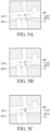
- FIG. 4A to FIG. 4E show modified potential field sub-maps of modified potential field maps at different time points according to some embodiments of the present invention.
- the processor 20 may select a plurality of time points of previous sequences (referred to as previous timing points later) of the collision time point corresponding to the collision zone BP (for example, the first time point t 010 and the second time point t 110 shown in FIG. 3 ) in equal proportion. For example, the processor 20 selects four previous timing points of the collision time point at an interval of 1 second.
- the first previous timing point is a time point before 4 seconds of the collision time point
- the second previous timing point is a point before 3 seconds of the collision time point
- the collision time point correspond to the first time point t 010 and the second time point t 110
- the first previous timing point may correspond to the first time point t 06 and the second time point t 16
- the second first previous timing point may correspond to the first time point t 07 and the second time point t 17 , and so on.
- the processor 20 may calculate the repulsive field of the dynamic object at different previous timing points and the collision time point according to Equation 2, and form the first repulsive object RP having the repulsive field at the corresponding collision zone BP of the original potential field map, so as to generate a modified potential field sub-map at a plurality of different time points.
- U rep ( q ) is a repulsive field value (that is, a strength of a repulsive field), ⁇ is a repulsive gain coefficient, D ( q ) is a distance between the corresponding coordinates of the initial path L1 of the mobile device and the corresponding coordinates of the predicted moving path L2 of the dynamic object at the different previous timing points and the collision time point, and Q* is an obstacle action range threshold of the dynamic object.
- the processor 20 connects the modified potential field sub-maps in series to form the modified potential field map.
- U rep q ⁇ 1 2 ⁇ 1 D q ⁇ 1 Q ⁇ 2 , D q ⁇ Q ⁇ 0 , D q > Q ⁇
- a first displacement point MV1 on the obstacle avoidance path LA is a position of the mobile device in the cost map at a current time point.
- the first displacement point MV1 on the obstacle avoidance path LA in FIG. 4A is the position of the mobile device in the cost map at the first previous timing point
- the first displacement point MV1 on the obstacle avoidance path LA in FIG. 4B is the position of the mobile device in the cost map at the second previous timing point
- the first displacement point MV1 on the obstacle avoidance path LA in FIG. 4E is the position of the mobile device in the cost map at the collision time point.
- a second displacement point MV2 on the predicted moving path L2 is a position of the dynamic object in the cost map at the current time point.
- the second displacement point MV1 on the predicted moving path L2 in FIG. 4A is the position of the dynamic object in the cost map at the first previous timing point
- the second displacement point MV2 on the predicted moving path L2 in FIG. 4B is the position of the dynamic object in the cost map at the second previous timing point
- the second displacement point MV2 on the predicted moving path L2 in FIG. 4E is the position of the dynamic object in the cost map at the collision time point. It can be seen from FIG. 4A to FIG.
- the dynamic object moves along the predicted moving path L2 to move increasingly closer to the collision zone BP where the predicted moving path L2 intersects the initial path L1, and the dynamic object collides with the mobile device moving on the initial path L1 in the collision zone BP at the collision time point.
- the initial path L1 may be modified to the obstacle avoidance path LA by forming the first repulsive object RP in the collision zone BP before the collision time point, so that the mobile device moves along the obstacle avoidance path LA, thereby avoiding the collision between the mobile device and the dynamic object in advance.
- the strength of the repulsive field of the first repulsive object RP is a tangent plane formed by the RPP in the first dimension X and the second dimension Y at the first time point t 07 and the second time point t 17 (as shown by a boundary size of the first repulsive object RP in FIG. 4B ), and so on.
- the strength of the repulsive field of the first repulsive object RP is a tangent plane formed by the RPP in the first dimension X and the second dimension Y at the first time point t 010 and the second time point t 110 (as shown by a boundary size of the first repulsive object RP in FIG. 4E ).
- the strength of the repulsive field of the first repulsive object RP changes with time. For example, prior to the collision time point, the strength of the repulsive field of the first repulsive object RP gradually increases with the increase of time (as shown in FIG. 4A to FIG. 4E , the boundary size of the first repulsive object RP gradually increases). In some embodiments, the strength of the repulsive field of the first repulsive object RP is at a maximum value at the collision time point corresponding to the collision zone BP.
- the strength of the repulsive field of the first repulsive object RP gradually increases with the increase of time, and the strength of the repulsive field of the first repulsive object RP gradually decreases with the increase of time after the collision time point.
- the strength of the repulsive field of the second repulsive object RPX is fixed compared with the first repulsive object RP.
- the strength of the repulsive field of the second repulsive object RPX is the same as the strength of the repulsive field of the first repulsive object RP at the collision time point corresponding to the collision zone BP.
- the strength of the repulsive field of the first repulsive object RP and the second repulsive object RPX correspond to a type of the dynamic object.
- some types of dynamic objects may cause bigger obstacles during moving of the mobile device, and some other types of dynamic objects may cause smaller obstacles during moving of the mobile device.
- a baby carriage causes a bigger obstacle than a pedestrian.
- ⁇ in Equation 2 may be 0.5
- Q* may be 0.5 m (meter).
- ⁇ in Equation 2 may be 1, and Q* may be 1 m (meter).
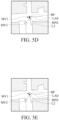
- FIG. 5A to FIG. 5E show modified potential field submaps of modified potential field maps at different time points according to a comparative example the present invention.
- a first displacement point MV1 on an obstacle avoidance path LAO is a position of the mobile device in the cost map at a current time point.
- the first displacement point MV1 on the obstacle avoidance path LAO in FIG. 5A is the position of the mobile device in the cost map at the first previous timing point
- the first displacement point MV1 on the obstacle avoidance path LAO in FIG. 5B is the position of the mobile device in the cost map at the second previous timing point, and so on.
- the first displacement point MV1 on the obstacle avoidance path LAO in FIG. 5E is the position of the mobile device in the cost map at the collision time point.
- a second displacement point MV2 on the predicted moving path L2 is a position of the dynamic object in the cost map at the current time point.
- the second displacement point MV2 on the predicted moving path L2 in FIG. 5A is the position of the dynamic object in the cost map at the first previous timing point
- the second displacement point MV2 on the predicted moving path L2 in FIG. 5B is the position of the dynamic object in the cost map at the second previous timing point
- the second displacement point MV2 on the predicted moving path L2 in FIG. 5E is the position of the dynamic object in the cost map at the collision time point.
- the processor 20 does not form the first repulsive object RP having the repulsive field at the corresponding collision zone BP of the original potential field map at the plurality of time points prior to the collision time point.
- the processor 20 modifies the initial path L1 to the obstacle avoidance path LAO only by forming, in the original potential field map, the second repulsive object RPX of the dynamic object that moves along the predicted moving path L2 over time.
- the processor 20 modifies the initial path L1 to the obstacle avoidance path LA through both the second repulsive object RPX and the first repulsive object RP.
- the processor 20 forms the first repulsive object RP having the repulsive field at the corresponding collision zone BP of the original potential field map at the collision time point and the different previous timing points prior to the collision time point.
- the strengths of the repulsive fields gradually increase with the increase of time prior to the collision time point. Therefore, compared with the comparison example, according to the embodiment of the present invention, the processor may be aware of the presence of the obstacle in advance, and update the obstacle avoidance path LA in real time, so that the mobile device can indeed avoid the obstacle when moving along the obstacle avoidance path LA. For example, in the comparison example, the processor 20 is not aware of the presence of the obstacle until the fourth previous timing point.
- the processor 20 is aware of the presence of the obstacle at the first previous timing point, and the mobile device moves along the obstacle avoidance path LA in which the first repulsive object RP is considered.
- the present invention further reduces a risk of turnover caused by quick turning of the mobile device during the moving in order to avoid the obstacle. For example, since the processor 20 is aware of the presence of the obstacle at the first previous timing point, the processor 20 may slow down the mobile device in advance and move along the obstacle avoidance path LA in which the first repulsive object RP is considered, so as to avoid the risk of turnover of the mobile device during the control of the movement of the mobile device along the obstacle avoidance path LA at the fourth previous timing point.
- the processor 20 inputs the modified potential field map into a neural network, and obtains the obstacle avoidance path LA through the operation of the neural network.
- the neural network may be implemented by the processor 20 or an additional calculating device through operation by using some algorithms. For example, the designer may input a plurality of modified potential field sample graphs having an obstacle avoidance sample path LS to the processor 20 (or a calculating device, and only the processor 20 is used as an example for ease of description) through an input/output interface.
- the neural network of the processor 20 performs continuous time recursive training according to the modified potential field sample graph, to determine a determination logic.
- the performs continuous time recursive training may be a known or self-developed model.
- the neural network may generate the obstacle avoidance path LA of the mobile device in the field domain according to the modified potential field map and the determination logic.
- the neural network includes a convolutional neural network and a liquid time-constant network (LTC) coupled to the convolutional neural network.
- the processor 20 generates the obstacle avoidance path LA through the modified potential field map and an artificial potential field method, or generates the obstacle avoidance path LA through the modified potential field map and the neural network (for example, the continuous time recursive neural network).
- a difference between the artificial potential field method and the neural network is that the operation may be performed through the artificial potential field method without prior training.
- a sequence feature may be learned through the neural network (for example, the liquid time-constant network), so that the obstacle avoidance path LA has better performance, and the obstacle avoidance path LA can have higher planning stability and is not easy to produce an endless loop.
- the neural network for example, the liquid time-constant network
- the processor 20 may calculate the obstacle avoidance path LA when determining that there is the collision zone BP, and therefore the processor 20 has a small operation burden.
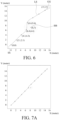
- FIG. 6 is a schematic diagram of an obstacle avoidance sample path LS according to some embodiments of the present invention.
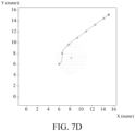
- FIG. 7A to FIG. 7D show modified potential field sample sub-maps of modified potential field sample maps at different time points according to some embodiments of the present invention. How to generate the modified potential field sample map and the obstacle avoidance sample path LS thereof is described below. It is assumed that preset start sample coordinates of an origin SS in a cost sample map in a cost sample map are (0, 0), target sample coordinates of a destination GG in the cost sample map are (15, 15), and sample coordinates of the collision zone BB are (8, 7).
- the processor 20 may calculate coordinates of each path point according to Equation 3, Equation 4, the start sample coordinates, the coordinates of the assumed current position of the mobile device (that is, a current path point), coordinates of the assumed current position of the dynamic object, the target sample coordinates, and a length of a step length of the mobile device per unit time, so as obtain the obstacle avoidance sample path LS.
- U att ( q ) is a gravitational field value (that is, the strength of a gravitational field)
- k is a gravitational gain coefficient
- G( q ) is a distance between the coordinates of the assumed current position (that is, a current path point) of the mobile device at a different time point and the target sample coordinates
- U reps ( q ) is a repulsive field value (that is, a strength of a repulsive field)
- ⁇ is a repulsive gain coefficient
- DD(q) is a distance between the coordinates of the assumed current position (that is, the current path point) of the mobile device and the coordinates of the assumed current position of the dynamic object at the different time point
- QQ ⁇ is an obstacle action rang threshold of the dynamic object.
- the processor 20 uses the start sample coordinates as coordinates of a first path point of the obstacle avoidance sample path LS. Next, the processor 20 calculates the strength of the gravitational field applied to the start sample coordinates according to Equation 3. For example, the strength of the gravitational field is (15, 15). The processor 20 calculates coordinates of a second path point by gradient descent in a direction of the start sample coordinates pointing to the target sample coordinates (that is, a direction of gravity).
- the gravitational field direction is, for example, (0.707, 0.707)
- the coordinates of the second path point is, for example, calculated by multiplying the gravitational field direction by the step length, that is to say, the coordinates of the second path point are, for example, (0.707,0.707) ⁇ 3 ⁇ (2.1,2.1).
- the second path point does not fall within the obstacle action range of the dynamic object (for example, a range of a circle formed by a radius of 3 m of the sample coordinates that does not fall within the collision zone)
- coordinates of a third path point and a fourth path point may be calculated in the manner in which the second path point is calculated.
- the coordinates of the third path point are (0.707,0.707) ⁇ 6 ⁇ (4.3,4.3)
- the coordinates of the fourth path point are (0.707,0.707) ⁇ 9 ⁇ (6.4,6.4).
- the processor 20 calculates the strength of the gravitational field applied to the fourth path point according to Equation 3.
- the strength of the gravitational field is (8.64, 8.64).
- the direction of the gravitational field applied to the fourth path point is still (0.707, 0.707).
- the processor 20 calculates the strength of the repulsive field applied to the fourth path point according to Equation 4.
- the strength of the repulsive field is (-8.19, -3.58).
- a direction of the repulsive field applied to the fourth path point is the direction in which the coordinates of the current position of the dynamic object point to the coordinates of the fourth path point.
- the repulsive field direction is (-0.925, -0.381).
- a direction of a resultant force applied to the fourth path point (referred to as a resultant direction below) is (0.088, 0.966).
- the processor 20 calculates coordinates of a fifth path point by gradient descent according to the coordinates of the fourth path point and the resultant direction.
- the coordinates of the fifth path point are, for example, a value calculated by multiplying the resultant direction by the step length plus the coordinates of the fourth path point. That is, the coordinates of the fifth path point are, for example, (6.4,6.4) + (0.088,0.996) ⁇ 3 ⁇ (6.6,9.4).
- the processor 20 performs the path point algorithm again until the finally calculated distance between the coordinates of the path point and the target sample coordinates is less than the step length. In this way, a plurality of path points forming the obstacle avoidance sample path LS can be obtained.
- the processor 20 combines the strengths of the repulsive fields of the dynamic object at different time points with the obstacle avoidance sample path LS and the cost sample map to form a plurality of modified potential field sample sub-maps at different time points. Then, the processor 20 connects the modified potential field sample sub-maps in series to form the modified potential field sample map for training of the neural network.
- the obstacle avoidance path that can really avoid the obstacle is obtained through the initial path of the mobile device, the predicted moving path of the dynamic object (that is, a dynamic obstacle), and a repulsive field of the first repulsive object in the collision zone between the initial path and the predicted moving path, so that the mobile device can smoothly reach the destination.
- the obstacle avoidance path may be further obtained through the second repulsive object formed by the dynamic object in addition to the first repulsive object.
Landscapes
- Engineering & Computer Science (AREA)
- Physics & Mathematics (AREA)
- General Physics & Mathematics (AREA)
- Automation & Control Theory (AREA)
- Aviation & Aerospace Engineering (AREA)
- Radar, Positioning & Navigation (AREA)
- Remote Sensing (AREA)
- Theoretical Computer Science (AREA)
- Computational Linguistics (AREA)
- Computing Systems (AREA)
- Biomedical Technology (AREA)
- Biophysics (AREA)
- Life Sciences & Earth Sciences (AREA)
- Data Mining & Analysis (AREA)
- Evolutionary Computation (AREA)
- General Health & Medical Sciences (AREA)
- Molecular Biology (AREA)
- Artificial Intelligence (AREA)
- General Engineering & Computer Science (AREA)
- Mathematical Physics (AREA)
- Software Systems (AREA)
- Health & Medical Sciences (AREA)
- Transportation (AREA)
- Mechanical Engineering (AREA)
- Control Of Position, Course, Altitude, Or Attitude Of Moving Bodies (AREA)
- Traffic Control Systems (AREA)
- Radar Systems Or Details Thereof (AREA)
Abstract
A trajectory correction method includes: determining whether there is a collision zone (BP) according to an initial path (L1) and a predicted moving path (L2) of a dynamic object; forming a first repulsive object (RP) at the corresponding collision zone (BP) of an original potential field map in response to determining that there is the collision zone (BP), to obtain a modified potential field map; and obtaining an obstacle avoidance path (LA) according to the modified potential field map.
Description
- The present invention relates to trajectory processing technologies, and in particular, to a trajectory correction system and a method therefor.
- Trajectory planning is one of the common steps in the field of automation. According to the integrity of environmental information, a trajectory planning method may be divided into two planning methods, such as global planning and local planning. The global planning requires obtaining in advance all environmental information of a field domain where a mobile device (such as a walking robot) is located, so as to plan a trajectory path along which the mobile device can avoid an obstacle to reach a destination in the field domain. The local planning is obtaining environmental information within a certain range of a current location of the mobile device in advance (referred to as local environmental information later), so as to gradually plan a trajectory path along which the mobile device can avoid an obstacle to reach a destination in the field domain. However, in addition to a static obstacle, there is a dynamic obstacle in the field domain, which makes it impossible to plan the trajectory path that can avoid the obstacle, and the mobile device cannot smoothly reach the destination.
- In view of the above, the present invention provides a trajectory correction system and a trajectory correction method. The trajectory correction system includes a memory and a processor. The processor is coupled to the memory. The memory is for storing a program code. The processor is for accessing and executing the program code to determine whether there is a collision zone according to an initial path and a predicted moving path of a dynamic object; form a first repulsive object at the corresponding collision zone of an original potential field map in response to determining that there is the collision zone, to obtain a modified potential field map; and generate an obstacle avoidance path according to the modified potential field map.
- The trajectory correction method includes: determining whether there is a collision zone according to an initial path and a predicted moving path of a dynamic object; forming a first repulsive object at the corresponding collision zone of an original potential field map in response to determining that there is the collision zone, to obtain a modified potential field map; and generating an obstacle avoidance path according to the modified potential field map.
- Based on the above, according to embodiments of the present invention, the obstacle avoidance path that can really avoid the obstacle is obtained through the initial path of the mobile device, the predicted moving path of the dynamic object (that is, a dynamic obstacle), and a repulsive field of the first repulsive object in the collision zone between the initial path and the predicted moving path, so that the mobile device can smoothly reach the destination. In some embodiments, the obstacle avoidance path may be further obtained through the repulsive object formed by the dynamic object (referred to as a second repulsive object later) in addition to the first repulsive object.
-
-
FIG. 1 is a schematic block diagram of a trajectory correction system according to some embodiments of the present invention. -
FIG. 2 is a flowchart of a trajectory correction method according to some embodiments of the present invention. -
FIG. 3 is a schematic diagram of an initial path and a predicted moving path in a three-dimensional space-time according to some embodiments of the present invention. -
FIG. 4A to FIG. 4E show modified potential field sub-maps of modified potential field maps at different time points according to some embodiments of the present invention. -
FIG. 5A to FIG. 5E show modified potential field sub-maps of modified potential field maps at different time points according to a comparative example the present invention. -
FIG. 6 is a schematic diagram of an obstacle avoidance sample path according to some embodiments of the present invention. -
FIG. 7A to FIG. 7D show modified potential field sample sub-maps of modified potential field sample maps at different time points according to some embodiments of the present invention. - A distance between two coordinates may mean a Euclidean distance herein.
-
FIG. 1 is a schematic block diagram of atrajectory correction system 100 according to some embodiments of the present invention. Thetrajectory correction system 100 includes amemory 10 and aprocessor 20. Theprocessor 20 is coupled to thememory 10. Thememory 10 stores a program code for theprocessor 20 to access and perform a trajectory correction method of the present invention. In some embodiments, thememory 10 and theprocessor 20 may be arranged inside or outside a mobile device (not shown). The mobile device is, for example, a walking robot. In some embodiments, transfer of data used by theprocessor 20 when performing the trajectory correction method of the present invention may be realized by using a robot operating system (ROS). - In some embodiments, the
memory 10 is, for example, but not limited to, a hard disk drive, a solid-state drive, a flash memory, an optical disk, and the like. In some embodiments, theprocessor 20 is, for example but not limited to an operational circuit such as a central processing unit, a microprocessor, an application-specific integrated circuit (ASIC), a system on a chip (SOC), or the like. In some embodiments, theprocessor 20 may be coupled to an input/output interface (not shown). The input/output interface may be connected to a control device (such as a keyboard, a mouse, and so on). The control device is operated by a designer to generate an operation instruction. The operation instruction is transmitted to theprocessor 20 through the input/output interface, so that theprocessor 20 executes a corresponding operation in response to the operation instruction. In another embodiment, theprocessor 20 and the mobile device may also transmit messages with each other through the input/output interface or a communication device (not shown). Theprocessor 20 receives image or sensing information (such as an image capture device and a depth camera) from the mobile device through the input/output interface or the communication device, and correspondingly processes the image or the sensing information (for example, performs image processing or data processing). Theprocessor 20 may also transmit a driving instruction to the mobile device through the input/output interface or the communication device, so as to control the mobile device to move. -
FIG. 2 is a flowchart of a trajectory correction method according to some embodiments of the present invention. First, theprocessor 20 obtains a field domain map from the memory 10 (step S201). The field domain map may be a top view of the field domain to which the mobile device is to move. Next, theprocessor 20 obtains start coordinates of the mobile device at an origin of the field domain (the field domain map) and target coordinates at a destination from thememory 10, and plans an initial path L1 according to the start coordinates and the target coordinates, so as to obtain the initial path L1 of the mobile device from the origin to the destination (step S203). Next, theprocessor 20 may obtain, from thememory 10, the image captured by the mobile device through the image capture device (such as, a camera) thereof during moving of the mobile device. Theprocessor 20 identifies a location and a type of an object (for example, a static object and a dynamic object, where the static object may be, for example, a wall, a table, a chair, or a vase with the position not easily changed, and the dynamic object may be, for example, a pedestrian, a baby carriage, an animal, a child, the elderly, and a vehicle with the position easily changed) in the image through an object detection algorithm (for example, feature matching or neural network inference), and transforms an angle of view of the image to project the object from the top to the field domain map and form a cost map (step S205). Next, theprocessor 20 tracks the trajectory generated by the object or obtains a historical moving trajectory of the dynamic object from thememory 10. Theprocessor 20 performs a trajectory prediction method according to the tracking trajectory and/or the historical moving trajectory to obtain a predicted moving path L2 of the dynamic object (step S207). The trajectory prediction method may be, for example, an algorithm implemented by a long short-term memory (LSTM) model, a social LSTM model, a social generative adversarial network (social GAN), or a SoPhie. In some embodiments, theprocessor 20 may combine the initial path L1 and the predicted moving path L2 into the cost map for performing the subsequent steps. - After obtaining the initial path L1 of the mobile device and the predicted moving path L2 of the dynamic object, the
processor 20 determines whether there is a collision zone BP according to the initial path L1 of the mobile device and the predicted moving path L2 of the dynamic object (step S209). For example, theprocessor 20 determines whether the initial path L1 and the predicted moving path L2 may intersect at a certain time point. In response to theprocessor 20 determining that the initial path L1 and the predicted moving path L2 possibly intersect at a certain time point, theprocessor 20 sets an intersecting area as the collision zone BP and performs step S211. In response to theprocessor 20 determining that the initial path L1 and the predicted moving path L2 impossibly intersect at a certain time point, theprocessor 20 performs step S205 and subsequent steps thereof, so as to successively predict the moving path of the dynamic object (that is, obtain the predicted moving path L2 of the dynamic object again) or wait until a new dynamic object is detected and predict the moving path thereof (that is, obtain the predicted moving path L2 of the new dynamic object). - After the collision zone BP is determined, the
processor 20 forms a first repulsive object RP at the corresponding collision zone BP of the original potential field map, to obtain the modified potential field map (step S211). For example, theprocessor 20 calculates a repulsive field of the static object and a gravitational field of the destination in the cost map according to an artificial potential field method, and combines the repulsive field of the static object and the gravitational field of the destination into the cost map to form the original potential field map. Since the initial path L1 and the predicted moving path L2 may be first combined into the cost map first, theprocessor 20 may learn a position of the collision zone BP corresponding to the original potential field map after determining the collision zone BP. Theprocessor 20 forms the first repulsive object RP of the repulsive field related to the dynamic object at the corresponding collision zone BP of the original potential field map, so as to generate the modified potential field map. - In some embodiments, the
processor 20 further forms a second repulsive object RPX moving along the predicted moving path L2 in the original potential field map, and obtains the modified potential field map according to the first repulsive object RP and the second repulsive object RPX. In other words, in addition to the first repulsive object RP, the modified potential field map further has the second repulsive object RPX. The first repulsive object RP and the second repulsive object RPX are associated with the same dynamic object. - After the modified potential field map is obtained, the
processor 20 obtains an obstacle avoidance path LA according to the modified potential field map (step S213). For example, since the mobile device is attracted by the gravitational field and repelled by the repulsive field, theprocessor 20 may calculate, through the resultant action of the gravitational force and the repulsive force in an artificial potential field, the obstacle avoidance path LA that can really avoid all obstacles (for example, the static object and the dynamic object). As shown inFIG. 4A to FIG. 4E , through the first repulsive object RP and the second repulsive object RPX, the obstacle avoidance path LA can bypass an upper portion of the repulsive field of the first repulsive object RP and the second repulsive object RPX without passing through the repulsive fields of the first repulsive object RP and the second repulsive object RPX and without passing through between a lower portion of the repulsive field of the first repulsive object RP and an upper portion of the repulsive field of the second repulsive object RPX. In some embodiments, theprocessor 20 generates a driving instruction according to the obstacle avoidance path LA, so that a driving device of the mobile device responds to the driving instruction and moves to the destination along the obstacle avoidance path LA. That is to say, theprocessor 20 controls the mobile device to move along the obstacle avoidance path LA. In some embodiments, the driving device may be implemented by a drivetrain and a driving wheel. The drivetrain may include a motor and a drive shaft connected to the driving wheel. - Referring to
FIG. 3, FIG. 3 is a schematic diagram of an initial path L1 and a predicted moving path L2 in a three-dimensional space-time according to some embodiments of the present invention. A first dimension X and a second dimension Y of the three-dimensional space-time represent a two-dimensional space of the cost map, and a third dimension T of the three-dimensional space-time represents time. In some embodiments, the initial path L1 includes a plurality of first coordinate parameters (x 01, y 01, t 01)-(x 010, y 010, t 010). In an embodiment, theprocessor 20 may calculate the parameters according to the initial path L1 and a moving speed of the mobile device. The predicted moving path L2 includes a plurality of second coordinate parameters (x 11, y 11, t 11)-(x 110, y 110, t 110). Ten first coordinate parameters and ten second coordinate parameters are drawn herein, but the present invention is not limited thereto. A quantity of the first coordinate parameters and a quantity of the second coordinate parameters may be respectively greater than ten or less than ten. In some embodiments of step S209, theprocessor 20 determines whether there is a collision zone BP according to the first coordinate parameters (x 01, y 01, t 01)-(x 010, y 010, t 010), the second coordinate parameters (x 11, y 11, t 11)-(x 110, y 110, t 110), and a distance threshold. In some embodiments, the distance threshold may be stored in amemory 10. - In some embodiments, since the initial path L1 and the predicted moving path L2 extend according to a time sequence, each of the first coordinate parameters (x 01, y 01, t 01)-(x 010, y 010, t 010) includes a first coordinate (x 01, y 01)-(x 010, y 010) and a first time interval formed by a first time point t 01-t 010. Specifically, the first coordinate parameter (x 01, y 01, t 01) includes the first coordinate (x 01, y 01) and the first time point t 01. The first coordinate parameter (x 02, y 02, t 02) includes the first coordinate (x 02, y 02) and the first time point t 02, and so on. The first coordinates (x 01, y 01)-(x 010, y 010) are respectively used for indicating a position of the initial path L1 in the cost map in the first time interval of the corresponding first time point t 01-t 010. Each of the second coordinate parameters (x 11, y 11, t 11)-(x 110, y 110, t 110) includes a second coordinate (x 11, y 11)-(x 110, y 110) and a second time interval formed by a second time points t 11-t 110. Specifically, the second coordinate parameter (x 11, y 11, t 11) includes the second coordinates (x 11, y 11) and the second time point t 11, the second coordinate parameter (x 12, y 12, t 12) includes the second coordinates (x 12, y 12) and the second time point t 12, and so on. The second coordinates (x 11, y 11)-(x 110, y 110) are respectively used for indicating a position of the predicted moving path L2 in the cost map in the second time interval of the corresponding second time points t 11-t 110. The first time points t 01-t 010 of the first coordinate parameters (x 01, y 01, t 01)-(x 010, y 010, t 010) are different. The second time points t 11-t 110 of the second coordinate parameters (x 11, y 11, t 11)-(x 110, y 110, t 110) are different. For example, the first time points t 01-t 010 are spaced apart from each other at equal intervals (for example, the interval between the first time points is 1 second), and the second time points t 11-t 110 are spaced apart from each other at equal intervals (for example, the interval between the second time points is 1 second).
- In some embodiments of step S209, the
processor 20 obtains a distance value according to the first coordinate (x 01, y 01)-(x 010, y 010) and the second coordinate (x 11, y 11)-(x 110, y 110) corresponding to the substantially identical first time point t 01-t 010 and second time point t 11-t 110. That is to say, theprocessor 20 compares the first coordinate (x 01, y 01)-(x 010, y 010) and the second coordinate (x 11, y 11)-(x 110, y 110) corresponding to the substantially identical first time point t 01-t 010 and second time point t 11-t 110 to obtain a distance value. In response to the distance value is not greater than the distance threshold, theprocessor 20 determines that there is a collision zone BP. The first coordinate (x 01, y 01)-(x 010, y 010) and the second coordinate (x 11, y 11)-(x 110, y 110) corresponding to the distance value not greater than the distance threshold are determined as the collision zone BP. Herein, the substantially identical time points may mean that a time difference between the time points is less than 1 millisecond. - Step S209 is illustrated below by assuming that the first time point t 01 and the second time point t 11 are both 0 seconds, the first time point t 02 and the second time point t 12 are both 1 second, and so on. The
processor 20 calculates Euclidean distances of the first coordinate (x 01, y 01)-(x 010, y 010) and the second coordinate (x 11, y 11)-(x 110, y 110) corresponding to the substantially identical first time point t 01-t 010 and second time point t 11-t 110 as distance values. Specifically, theprocessor 20 calculates the Euclidean distance between the first coordinates (x 01, y 01) and the second coordinates (x 11, y 11) as the distance value based on Equation 1, calculates the Euclidean distance between the first coordinates (x 02, y 02) and the second coordinates (x 12, y 12) as the distance value, and so on. D is a distance value, x 0n is a first dimension of the first coordinates, x 1n is a first dimension of the second coordinates, y 0n is a second dimension of the first coordinates, y 1n is a second dimension of the second coordinates, and n is a constant. When the distance value is not greater than the distance threshold, it means that the initial path L1 and the predicted moving path L2 intersect at the corresponding first time point t 01-t 010 and second time point t 11-t 110 (that is, a collision time point) during calculation of the distance value. For example, as shown inFIG. 3 , the initial path L1 and the predicted moving path L2 intersect at the first time point t 010 and the second time point t 110. Therefore, theprocessor 20 may obtain the collision zone BP according to the first coordinate (x 010, y 010) and the second coordinate (x 110, y 110) corresponding to the first time point t 010 and the second time point t 110. For example, the coordinate of a central point between the first coordinates (x 010, y 010) and the second coordinates (x 110, y 110) are determined as the collision zone BP, or the distance value between the first coordinate (x 010, y 010) and the second coordinate (x 110, y 110) is used as a radius or a diameter to calculate a circular area as the collision zone BP, but the present invention is not limited thereto. The distance value may be used as a side length of a polygon to calculate a polygonal area as the collision zone BP. In other words, the collision zone BP may be a point or an area.

- In some embodiments, the distance threshold corresponds to a size of the dynamic object. Specifically, the distance threshold is less than the size of the dynamic object. In some embodiments, the distance threshold may be a sum of half a size of the mobile device (referred to as a half size below) (for example, a radius) and half the size of the dynamic object (for example, the radius). In this way, it is ensured that it may be determined whether there is the collision zone BP between the initial path L1 and the predicted moving path L2.
- Refer to
FIG. 3 andFIG. 4A toFIG. 4E .FIG. 4A to FIG. 4E show modified potential field sub-maps of modified potential field maps at different time points according to some embodiments of the present invention. In some embodiments, theprocessor 20 may select a plurality of time points of previous sequences (referred to as previous timing points later) of the collision time point corresponding to the collision zone BP (for example, the first time point t 010 and the second time point t 110 shown inFIG. 3 ) in equal proportion. For example, theprocessor 20 selects four previous timing points of the collision time point at an interval of 1 second. Specifically, the first previous timing point is a time point before 4 seconds of the collision time point, the second previous timing point is a point before 3 seconds of the collision time point, and so on. As shown inFIG. 3 , the collision time point correspond to the first time point t 010 and the second time point t 110. The first previous timing point may correspond to the first time point t 06 and the second time point t 16, the second first previous timing point may correspond to the first time point t 07 and the second time point t 17, and so on. Theprocessor 20 may calculate the repulsive field of the dynamic object at different previous timing points and the collision time point according toEquation 2, and form the first repulsive object RP having the repulsive field at the corresponding collision zone BP of the original potential field map, so as to generate a modified potential field sub-map at a plurality of different time points. Urep (q) is a repulsive field value (that is, a strength of a repulsive field), η is a repulsive gain coefficient, D(q) is a distance between the corresponding coordinates of the initial path L1 of the mobile device and the corresponding coordinates of the predicted moving path L2 of the dynamic object at the different previous timing points and the collision time point, and Q* is an obstacle action range threshold of the dynamic object. Then theprocessor 20 connects the modified potential field sub-maps in series to form the modified potential field map.

- In
FIG. 4A to FIG. 4E , a first displacement point MV1 on the obstacle avoidance path LA is a position of the mobile device in the cost map at a current time point. For example, the first displacement point MV1 on the obstacle avoidance path LA inFIG. 4A is the position of the mobile device in the cost map at the first previous timing point, the first displacement point MV1 on the obstacle avoidance path LA inFIG. 4B is the position of the mobile device in the cost map at the second previous timing point, and so on. Moreover, the first displacement point MV1 on the obstacle avoidance path LA inFIG. 4E is the position of the mobile device in the cost map at the collision time point. InFIG. 4A to FIG. 4E , a second displacement point MV2 on the predicted moving path L2 is a position of the dynamic object in the cost map at the current time point. For example, the second displacement point MV1 on the predicted moving path L2 inFIG. 4A is the position of the dynamic object in the cost map at the first previous timing point, the second displacement point MV2 on the predicted moving path L2 inFIG. 4B is the position of the dynamic object in the cost map at the second previous timing point, and so on. Moreover, the second displacement point MV2 on the predicted moving path L2 inFIG. 4E is the position of the dynamic object in the cost map at the collision time point. It can be seen fromFIG. 4A to FIG. 4E that with the increase of time, the dynamic object moves along the predicted moving path L2 to move increasingly closer to the collision zone BP where the predicted moving path L2 intersects the initial path L1, and the dynamic object collides with the mobile device moving on the initial path L1 in the collision zone BP at the collision time point. Therefore, the initial path L1 may be modified to the obstacle avoidance path LA by forming the first repulsive object RP in the collision zone BP before the collision time point, so that the mobile device moves along the obstacle avoidance path LA, thereby avoiding the collision between the mobile device and the dynamic object in advance. - As shown in
FIG. 3 , a repulsive force pattern (RPP) composed of repulsive fields at different previous timing points and the collision time points calculated byEquation 2 is shown. In some embodiments, at the first previous timing point, the strength of the repulsive field of the first repulsive object RP is a tangent plane formed by the RPP in the first dimension X and the second dimension Y at the first time point t 06 and the second time point t 16 (as shown by a boundary size of the first repulsive object RP inFIG. 4A ). At the second previous timing point, the strength of the repulsive field of the first repulsive object RP is a tangent plane formed by the RPP in the first dimension X and the second dimension Y at the first time point t 07 and the second time point t 17 (as shown by a boundary size of the first repulsive object RP inFIG. 4B ), and so on. At the collision time point, the strength of the repulsive field of the first repulsive object RP is a tangent plane formed by the RPP in the first dimension X and the second dimension Y at the first time point t 010 and the second time point t 110 (as shown by a boundary size of the first repulsive object RP inFIG. 4E ). - In some embodiments, as shown in
FIG. 3 andFIG. 4A toFIG. 4E , it can be seen that the strength of the repulsive field of the first repulsive object RP changes with time. For example, prior to the collision time point, the strength of the repulsive field of the first repulsive object RP gradually increases with the increase of time (as shown inFIG. 4A to FIG. 4E , the boundary size of the first repulsive object RP gradually increases). In some embodiments, the strength of the repulsive field of the first repulsive object RP is at a maximum value at the collision time point corresponding to the collision zone BP. That is to say, before the collision time point, the strength of the repulsive field of the first repulsive object RP gradually increases with the increase of time, and the strength of the repulsive field of the first repulsive object RP gradually decreases with the increase of time after the collision time point. In some embodiments, the strength of the repulsive field of the second repulsive object RPX is fixed compared with the first repulsive object RP. In some embodiments, the strength of the repulsive field of the second repulsive object RPX is the same as the strength of the repulsive field of the first repulsive object RP at the collision time point corresponding to the collision zone BP. - In some embodiments, the strength of the repulsive field of the first repulsive object RP and the second repulsive object RPX correspond to a type of the dynamic object. Specifically, some types of dynamic objects may cause bigger obstacles during moving of the mobile device, and some other types of dynamic objects may cause smaller obstacles during moving of the mobile device. For example, a baby carriage causes a bigger obstacle than a pedestrian. Specifically, in a case that the type of the dynamic object is the pedestrian, η in
Equation 2 may be 0.5, and Q* may be 0.5 m (meter). In a case that the type of the dynamic object is the baby carriage, η inEquation 2 may be 1, and Q* may be 1 m (meter). In this case, when D(q) is 0.5 m (meter), Urep (q) is 0.25 in the case that the type of the dynamic object is the pedestrian, and Urep (q) is 0.5 in the case that the dynamic object is the baby carriage. That is to say, the baby carriage has a larger strength of the repulsive field than the pedestrian. - Refer to
FIG. 4A to FIG. 4E andFIG. 5Ato FIG. 5E. FIG. 5A to FIG. 5E show modified potential field submaps of modified potential field maps at different time points according to a comparative example the present invention. InFIG. 5A to FIG. 5E , a first displacement point MV1 on an obstacle avoidance path LAO is a position of the mobile device in the cost map at a current time point. For example, the first displacement point MV1 on the obstacle avoidance path LAO inFIG. 5A is the position of the mobile device in the cost map at the first previous timing point, the first displacement point MV1 on the obstacle avoidance path LAO inFIG. 5B is the position of the mobile device in the cost map at the second previous timing point, and so on. Moreover, the first displacement point MV1 on the obstacle avoidance path LAO inFIG. 5E is the position of the mobile device in the cost map at the collision time point. InFIG. 5A to FIG. 5E , a second displacement point MV2 on the predicted moving path L2 is a position of the dynamic object in the cost map at the current time point. For example, the second displacement point MV2 on the predicted moving path L2 inFIG. 5A is the position of the dynamic object in the cost map at the first previous timing point, the second displacement point MV2 on the predicted moving path L2 inFIG. 5B is the position of the dynamic object in the cost map at the second previous timing point, and so on. Moreover, the second displacement point MV2 on the predicted moving path L2 inFIG. 5E is the position of the dynamic object in the cost map at the collision time point. - In the comparison example, the
processor 20 does not form the first repulsive object RP having the repulsive field at the corresponding collision zone BP of the original potential field map at the plurality of time points prior to the collision time point. Theprocessor 20 modifies the initial path L1 to the obstacle avoidance path LAO only by forming, in the original potential field map, the second repulsive object RPX of the dynamic object that moves along the predicted moving path L2 over time. Compared with the comparison example, in the embodiment of the present invention, theprocessor 20 modifies the initial path L1 to the obstacle avoidance path LA through both the second repulsive object RPX and the first repulsive object RP. Specifically, theprocessor 20 forms the first repulsive object RP having the repulsive field at the corresponding collision zone BP of the original potential field map at the collision time point and the different previous timing points prior to the collision time point. The strengths of the repulsive fields gradually increase with the increase of time prior to the collision time point. Therefore, compared with the comparison example, according to the embodiment of the present invention, the processor may be aware of the presence of the obstacle in advance, and update the obstacle avoidance path LA in real time, so that the mobile device can indeed avoid the obstacle when moving along the obstacle avoidance path LA. For example, in the comparison example, theprocessor 20 is not aware of the presence of the obstacle until the fourth previous timing point. In the embodiment of the present invention, theprocessor 20 is aware of the presence of the obstacle at the first previous timing point, and the mobile device moves along the obstacle avoidance path LA in which the first repulsive object RP is considered. In addition, the present invention further reduces a risk of turnover caused by quick turning of the mobile device during the moving in order to avoid the obstacle. For example, since theprocessor 20 is aware of the presence of the obstacle at the first previous timing point, theprocessor 20 may slow down the mobile device in advance and move along the obstacle avoidance path LA in which the first repulsive object RP is considered, so as to avoid the risk of turnover of the mobile device during the control of the movement of the mobile device along the obstacle avoidance path LA at the fourth previous timing point. - In some embodiments of step S213, the
processor 20 inputs the modified potential field map into a neural network, and obtains the obstacle avoidance path LA through the operation of the neural network. The neural network may be implemented by theprocessor 20 or an additional calculating device through operation by using some algorithms. For example, the designer may input a plurality of modified potential field sample graphs having an obstacle avoidance sample path LS to the processor 20 (or a calculating device, and only theprocessor 20 is used as an example for ease of description) through an input/output interface. The neural network of theprocessor 20 performs continuous time recursive training according to the modified potential field sample graph, to determine a determination logic. The performs continuous time recursive training may be a known or self-developed model. The neural network may generate the obstacle avoidance path LA of the mobile device in the field domain according to the modified potential field map and the determination logic. In some embodiments, the neural network includes a convolutional neural network and a liquid time-constant network (LTC) coupled to the convolutional neural network. In some embodiments, theprocessor 20 generates the obstacle avoidance path LA through the modified potential field map and an artificial potential field method, or generates the obstacle avoidance path LA through the modified potential field map and the neural network (for example, the continuous time recursive neural network). A difference between the artificial potential field method and the neural network is that the operation may be performed through the artificial potential field method without prior training. Compared with the artificial potential field method, a sequence feature may be learned through the neural network (for example, the liquid time-constant network), so that the obstacle avoidance path LA has better performance, and the obstacle avoidance path LA can have higher planning stability and is not easy to produce an endless loop. In addition, since a quantity of parameters in the neural network architecture is fixed, the execution speed is stable, a calculation speed is fast, and a response time is short in the case of a plurality of dynamic objects. In addition, through the neural network (for example, the liquid time-constant network), theprocessor 20 may calculate the obstacle avoidance path LA when determining that there is the collision zone BP, and therefore theprocessor 20 has a small operation burden. - Refer to
FIG. 6 and FIG. 7A toFIG. 7D .FIG 6 is a schematic diagram of an obstacle avoidance sample path LS according to some embodiments of the present invention.FIG. 7A to FIG. 7D show modified potential field sample sub-maps of modified potential field sample maps at different time points according to some embodiments of the present invention. How to generate the modified potential field sample map and the obstacle avoidance sample path LS thereof is described below. It is assumed that preset start sample coordinates of an origin SS in a cost sample map in a cost sample map are (0, 0), target sample coordinates of a destination GG in the cost sample map are (15, 15), and sample coordinates of the collision zone BB are (8, 7). Theprocessor 20 may calculate coordinates of each path point according to Equation 3,Equation 4, the start sample coordinates, the coordinates of the assumed current position of the mobile device (that is, a current path point), coordinates of the assumed current position of the dynamic object, the target sample coordinates, and a length of a step length of the mobile device per unit time, so as obtain the obstacle avoidance sample path LS.Uatt (q) is a gravitational field value (that is, the strength of a gravitational field), k is a gravitational gain coefficient, G(q) is a distance between the coordinates of the assumed current position (that is, a current path point) of the mobile device at a different time point and the target sample coordinates, Ureps (q) is a repulsive field value (that is, a strength of a repulsive field), η is a repulsive gain coefficient, DD(q) is a distance between the coordinates of the assumed current position (that is, the current path point) of the mobile device and the coordinates of the assumed current position of the dynamic object at the different time point, and QQ ∗ is an obstacle action rang threshold of the dynamic object.


- In the following, specifically, it is assumed that a step length of the mobile device per second is 3 m, QQ ∗ is 3 m, k is 1, and η is 1.5. The
processor 20 uses the start sample coordinates as coordinates of a first path point of the obstacle avoidance sample path LS. Next, theprocessor 20 calculates the strength of the gravitational field applied to the start sample coordinates according to Equation 3. For example, the strength of the gravitational field is (15, 15). Theprocessor 20 calculates coordinates of a second path point by gradient descent in a direction of the start sample coordinates pointing to the target sample coordinates (that is, a direction of gravity). The gravitational field direction is, for example, (0.707, 0.707), and the coordinates of the second path point is, for example, calculated by multiplying the gravitational field direction by the step length, that is to say, the coordinates of the second path point are, for example, (0.707,0.707) × 3 ≈ (2.1,2.1). Then, since the second path point does not fall within the obstacle action range of the dynamic object (for example, a range of a circle formed by a radius of 3 m of the sample coordinates that does not fall within the collision zone), coordinates of a third path point and a fourth path point may be calculated in the manner in which the second path point is calculated. For example, the coordinates of the third path point are (0.707,0.707) × 6 ≈ (4.3,4.3), and the coordinates of the fourth path point are (0.707,0.707) × 9 ≈ (6.4,6.4). - In the following, since the fourth path point falls within the obstacle action range of the dynamic object, the
processor 20 calculates the strength of the gravitational field applied to the fourth path point according to Equation 3. For example, the strength of the gravitational field is (8.64, 8.64). In this case, the direction of the gravitational field applied to the fourth path point is still (0.707, 0.707). Theprocessor 20 calculates the strength of the repulsive field applied to the fourth path point according toEquation 4. For example, the strength of the repulsive field is (-8.19, -3.58). In this case, a direction of the repulsive field applied to the fourth path point is the direction in which the coordinates of the current position of the dynamic object point to the coordinates of the fourth path point. For example, the repulsive field direction is (-0.925, -0.381). In this way, a direction of a resultant force applied to the fourth path point (referred to as a resultant direction below) is (0.088, 0.966). Next, theprocessor 20 calculates coordinates of a fifth path point by gradient descent according to the coordinates of the fourth path point and the resultant direction. The coordinates of the fifth path point are, for example, a value calculated by multiplying the resultant direction by the step length plus the coordinates of the fourth path point. That is, the coordinates of the fifth path point are, for example, (6.4,6.4) + (0.088,0.996) × 3 ≈ (6.6,9.4). Theprocessor 20 performs the path point algorithm again until the finally calculated distance between the coordinates of the path point and the target sample coordinates is less than the step length. In this way, a plurality of path points forming the obstacle avoidance sample path LS can be obtained. Theprocessor 20 combines the strengths of the repulsive fields of the dynamic object at different time points with the obstacle avoidance sample path LS and the cost sample map to form a plurality of modified potential field sample sub-maps at different time points. Then, theprocessor 20 connects the modified potential field sample sub-maps in series to form the modified potential field sample map for training of the neural network. - Based on the above, according to embodiments of the present invention, the obstacle avoidance path that can really avoid the obstacle is obtained through the initial path of the mobile device, the predicted moving path of the dynamic object (that is, a dynamic obstacle), and a repulsive field of the first repulsive object in the collision zone between the initial path and the predicted moving path, so that the mobile device can smoothly reach the destination. In some embodiments, the obstacle avoidance path may be further obtained through the second repulsive object formed by the dynamic object in addition to the first repulsive object.
Claims (15)
- A trajectory correction system (100), comprising:a memory (10), for storing a program code; anda processor (20), coupled to the memory (10), for accessing and executing the program code to:determine whether there is a collision zone (BP) according to an initial path (L1) and a predicted moving path (L2) of a dynamic object;form a first repulsive object (RP) at the corresponding collision zone (BP) of an original potential field map in response to determining that there is the collision zone (BP), to obtain a modified potential field map; andgenerate an obstacle avoidance path (LA) according to the modified potential field map.
- The trajectory correction system (100) according to claim 1, characterized in that the processor (20) forms a second repulsive object (RPX) moving along the predicted moving path (L2) in the original potential field map, and obtains the modified potential field map according to the first repulsive object (RP) and the second repulsive object (RPX).
- The trajectory correction system (100) according to claim 2, characterized in that a strength of a repulsive field of the first repulsive object (RP) or the second repulsive object (RPX) corresponds to a type of the dynamic object.
- The trajectory correction system (100) according to claim 1, characterized in that the processor (20) inputs the modified potential field map into a neural network to obtain the obstacle avoidance path (LA), wherein the neural network comprises a convolutional neural network and a liquid time-constant network (LTC).
- The trajectory correction system (100) according to claim 1, characterized in that the initial path (L1) comprises a plurality of first coordinate parameters ( (x 01,y 01,t 01) ~ (x 010,y 010,t 010) ), the predicted moving path (L2) comprises a plurality of second coordinate parameters ( (x 11,y 11,t 11) ~ (x 110,y 110,t 110) ), and the processor (20) determines whether there is the collision zone (BP) according to the first coordinate parameters ( (x 01, y 01,t 01) ~ (x 010,y 010,t 010) ), the second coordinate parameters ( (x 11,y 11,t 11) ~ (x 110,y 110,t 110) ), and a distance threshold.
- The trajectory correction system (100) according to claim 5, characterized in that each of the first coordinate parameters ( ( x 01,y 01,t 01 ) ~ (x 010,y 010,t 010) ) comprises a first coordinate ( (x 01,y 01) ~ (x 010,y 010) ) and a first time point (t 01∼t 010), each of the second coordinate parameters ( ( x 11,y 11,t 11) ~ (x 110,y 110,t 110) ) comprises a second coordinate ( (x 11,y 11) ~ (x 110,y 110) ) and a second time point (t 11∼t 110), and the processor (20) obtains a distance value according to the first coordinate ( (x 01,y 01) ~ (x 010,y 010) ) corresponding to the first time point (t 01∼t 010) and the second coordinate ( (x 11,y 11) ~ (x 110,y 110) ) corresponding to the second time point (t 11∼t 110) , determines that there is the collision zone (BP) in response to the distance value is not greater than the distance threshold, and determines the first coordinates ( (x 01,y 01) ~ (x 010,y 010) ) and the second coordinates ( (x 11,y 11) ~ (x 110,y 110) ) corresponding to the distance value as the collision zone (BP), wherein the distance threshold is a size corresponding to the dynamic object.
- The trajectory correction system (100) according to claim 1, characterized in that a strength of a repulsive field of the first repulsive object (RP) corresponding to the collision zone (BP) changes with time, and the strength of the repulsive field of the first repulsive object (RP) is at a maximum value at a collision time point corresponding to the collision zone (BP).
- The trajectory correction system (100) according to claim 1, characterized in that the processor (20) controls a driving device of a mobile device to move along the obstacle avoidance path (LA).
- A trajectory correction method, comprising:determining whether there is a collision zone (BP) according to an initial path (L1) and a predicted moving path (L2) of a dynamic object;forming a first repulsive object (RP) at the corresponding collision zone (BP) of an original potential field map in response to determining that there is the collision zone (BP), to obtain a modified potential field map; andgenerating an obstacle avoidance path (LA) according to the modified potential field map.
- The trajectory correction method according to claim 9, characterized in that a second repulsive object (RPX) moving along the predicted moving path (L2) is formed in the original potential field map, and the modified potential field map is obtained according to the first repulsive object (RP) and the second repulsive object (RPX), wherein a strength of a repulsive field of the first repulsive object (RP) or the second repulsive object (RPX) corresponds to a type of the dynamic obj ect.
- The trajectory correction method according to claim 9, characterized in that the modified potential field map is inputted into a neural network to obtain the obstacle avoidance path (LA), wherein the neural network comprises a convolutional neural network and a liquid time-constant network (LTC).
- The trajectory correction method according to claim 9, characterized in that the initial path (L1) comprises a plurality of first coordinate parameters ( (x 01,y 01,t 01 ) ~ (x 010,y 010,t 010) ), the predicted moving path (L2) comprises a plurality of second coordinate parameters ((x 11,y 11,t 11)~(x 110,y 110,t 110)), and the collision zone (BP) is determined according to the first coordinate parameters ( (x 01,y 01,t 01) ~ (x 010,y 010,t 010) ), the second coordinate parameters ( (x 11,y 11,t 11) ~ (x 110,y 110,t 110) ), and a distance threshold.
- The trajectory correction method according to claim 12, characterized in that each of the first coordinate parameters ( (x 01,y 01,t 01) ~ (x 010,y 010,t 010) ) comprises a first coordinate ( (x 01,y 01 ) ~ (x 010,y 010) ) and a first time point (t 01∼t 010), each of the second coordinate parameters ( (x 11,y 11,t 11) ~ (x 110,y 110,t 110) ) comprises a second coordinate ( (x 11,y 11) ~ (x 110,y 110) ) and a second time point (t 11∼t 110), obtaining a distance value according to the first coordinate ( (x 01,y 01) ~ (x 010,y 010) ) corresponding to the first time point (t 01∼t 010) and the second coordinate corresponding ( (x 11,y 11) ~ (x 110,y 110) ) to the second time point (t 11∼t 110), the collision zone (BP) is determined in response to the distance value is not greater than the distance threshold, and the first coordinates ( (x 01,y 01) ~ (x 010,y 010) ) and the second coordinates ( (x 11,y 11) ~ (x 110,y 110) ) corresponding to the distance value are determined as the collision zone (BP), wherein the distance threshold is a size corresponding to the dynamic object.
- The trajectory correction method according to claim 9, characterized in that a strength of a repulsive field of the first repulsive object (RP) corresponding to the collision zone (BP) changes with time, and the strength of the repulsive field of the first repulsive object (RP) is at a maximum value at a collision time point corresponding to the collision zone (BP).
- The trajectory correction method according to claim 9, characterized in that comprising controlling a driving device of a mobile device to move along the obstacle avoidance path (LA).
Applications Claiming Priority (1)
| Application Number | Priority Date | Filing Date | Title |
|---|---|---|---|
| TW111150229A TWI846244B (en) | 2022-12-27 | 2022-12-27 | Trajectory correction system and method thereof |
Publications (1)
| Publication Number | Publication Date |
|---|---|
| EP4394538A1 true EP4394538A1 (en) | 2024-07-03 |
Family
ID=85776106
Family Applications (1)
| Application Number | Title | Priority Date | Filing Date |
|---|---|---|---|
| EP23164341.2A Pending EP4394538A1 (en) | 2022-12-27 | 2023-03-27 | Trajectory correction system and method therefor |
Country Status (5)
| Country | Link |
|---|---|
| US (1) | US12539849B2 (en) |
| EP (1) | EP4394538A1 (en) |
| JP (1) | JP7499898B1 (en) |
| CN (1) | CN118276565A (en) |
| TW (1) | TWI846244B (en) |
Families Citing this family (2)
| Publication number | Priority date | Publication date | Assignee | Title |
|---|---|---|---|---|
| US20250033661A1 (en) * | 2023-07-26 | 2025-01-30 | Aptiv Technologies Limited | Trajectory Planning in a Three-Dimensional Search Space with a Space-Time Artificial Potential Field |
| CN119197548B (en) * | 2024-11-29 | 2025-03-04 | 南京邮电大学 | A static path planning method for warehouse AGV based on improved artificial potential field method |
Citations (2)
| Publication number | Priority date | Publication date | Assignee | Title |
|---|---|---|---|---|
| US11016491B1 (en) * | 2018-01-26 | 2021-05-25 | X Development Llc | Trajectory planning for mobile robots |
| EP3995396A1 (en) * | 2019-07-05 | 2022-05-11 | Sony Group Corporation | Information processing device, information processing method, program, and information processing system |
Family Cites Families (24)
| Publication number | Priority date | Publication date | Assignee | Title |
|---|---|---|---|---|
| KR100670565B1 (en) * | 2004-04-01 | 2007-01-18 | 재단법인서울대학교산학협력재단 | Collision avoidance method of multi-object robot using extended collision map and computer readable recording medium recording the method |
| EP2829939B1 (en) * | 2005-12-02 | 2019-11-13 | iRobot Corporation | Autonomous coverage robot navigation system |
| JP5112666B2 (en) * | 2006-09-11 | 2013-01-09 | 株式会社日立製作所 | Mobile device |
| JP2008242859A (en) * | 2007-03-27 | 2008-10-09 | Sony Corp | Object motion control apparatus, motion control method, and computer program |
| CN100570523C (en) | 2008-08-18 | 2009-12-16 | 浙江大学 | An Obstacle Avoidance Method for Mobile Robots Based on Obstacle Motion Prediction |
| CN102591332B (en) | 2011-01-13 | 2014-08-13 | 同济大学 | Device and method for local path planning of pilotless automobile |
| US8466807B2 (en) * | 2011-06-01 | 2013-06-18 | GM Global Technology Operations LLC | Fast collision detection technique for connected autonomous and manual vehicles |
| CN102999050B (en) | 2012-12-13 | 2015-04-08 | 哈尔滨工程大学 | Automatic obstacle avoidance method for intelligent underwater robots |
| US9216745B2 (en) * | 2013-09-16 | 2015-12-22 | Disney Enterprises, Inc. | Shared control of semi-autonomous vehicles including collision avoidance in multi-agent scenarios |
| DE102014201382A1 (en) | 2014-01-27 | 2015-07-30 | Robert Bosch Gmbh | Method for operating a driver assistance system and driver assistance system |
| CN105223956B (en) | 2015-11-09 | 2018-02-27 | 中山大学 | A kind of dynamic obstacle avoidance method of omni-directional mobile robots |
| US10788836B2 (en) * | 2016-02-29 | 2020-09-29 | AI Incorporated | Obstacle recognition method for autonomous robots |
| US11927965B2 (en) * | 2016-02-29 | 2024-03-12 | AI Incorporated | Obstacle recognition method for autonomous robots |
| KR102100476B1 (en) * | 2018-05-04 | 2020-05-26 | 엘지전자 주식회사 | A plurality of robot cleaner and a controlling method for the same |
| JP2020030601A (en) * | 2018-08-22 | 2020-02-27 | アイシン・エィ・ダブリュ株式会社 | Vehicle driving assistance system, vehicle driving assistance method, and vehicle driving assistance program |
| JP2020095635A (en) * | 2018-12-14 | 2020-06-18 | パナソニックIpマネジメント株式会社 | Vehicle control device, vehicle control method, vehicle control program, non-transitory recording medium, and vehicle |
| WO2020136769A1 (en) * | 2018-12-26 | 2020-07-02 | 三菱電機株式会社 | Robot control device, robot control learning device, and robot control method |
| TWI756647B (en) * | 2020-03-18 | 2022-03-01 | 財團法人船舶暨海洋產業研發中心 | A vessel collision avoiding method and system based on artificial potential field |
| US12077190B2 (en) * | 2020-05-18 | 2024-09-03 | Nvidia Corporation | Efficient safety aware path selection and planning for autonomous machine applications |
| CN113960996B (en) * | 2020-07-20 | 2025-05-23 | 华为技术有限公司 | Obstacle avoidance path planning method and device of driving device |
| TWI780468B (en) * | 2020-08-13 | 2022-10-11 | 國立陽明交通大學 | Method and system of robot for human following |
| KR20220055167A (en) * | 2020-10-26 | 2022-05-03 | 주식회사 케이티 | Autonomous robot, world map management server of autonomous robot and collision avoidance method using the same |
| CN114620058B (en) * | 2020-12-10 | 2024-11-29 | 深圳引望智能技术有限公司 | Track planning method, apparatus, computing device, moving object, and storage medium |
| US20220315047A1 (en) * | 2021-03-30 | 2022-10-06 | Honda Research Institute Europe Gmbh | Method, system and vehicle with an uncertainty-based lane positioning control |
-
2022
- 2022-12-27 TW TW111150229A patent/TWI846244B/en active
-
2023
- 2023-02-03 CN CN202310081021.XA patent/CN118276565A/en active Pending
- 2023-02-09 JP JP2023018232A patent/JP7499898B1/en active Active
- 2023-03-17 US US18/185,508 patent/US12539849B2/en active Active
- 2023-03-27 EP EP23164341.2A patent/EP4394538A1/en active Pending
Patent Citations (2)
| Publication number | Priority date | Publication date | Assignee | Title |
|---|---|---|---|---|
| US11016491B1 (en) * | 2018-01-26 | 2021-05-25 | X Development Llc | Trajectory planning for mobile robots |
| EP3995396A1 (en) * | 2019-07-05 | 2022-05-11 | Sony Group Corporation | Information processing device, information processing method, program, and information processing system |
Also Published As
| Publication number | Publication date |
|---|---|
| TW202427084A (en) | 2024-07-01 |
| US20240208493A1 (en) | 2024-06-27 |
| TWI846244B (en) | 2024-06-21 |
| CN118276565A (en) | 2024-07-02 |
| US12539849B2 (en) | 2026-02-03 |
| JP2024094195A (en) | 2024-07-09 |
| JP7499898B1 (en) | 2024-06-14 |
Similar Documents
| Publication | Publication Date | Title |
|---|---|---|
| US12046131B2 (en) | Autonomous vehicle planning and prediction | |
| US10748061B2 (en) | Simultaneous localization and mapping with reinforcement learning | |
| JP6917878B2 (en) | Mobile behavior prediction device | |
| EP1733287B1 (en) | System and method for adaptive path planning | |
| WO2020243162A1 (en) | Methods and systems for trajectory forecasting with recurrent neural networks using inertial behavioral rollout | |
| US11934176B2 (en) | Device and method for controlling a robot | |
| CN113311862B (en) | Movement planning method for robot to avoid obstacles | |
| US12539849B2 (en) | Trajectory correction system and method therefor | |
| KR20160048530A (en) | Method and apparatus for generating pathe of autonomous vehicle | |
| CN117055601B (en) | A method, device, equipment and storage medium for planning a meal delivery route by drone | |
| Quinones-Ramirez et al. | Robot path planning using deep reinforcement learning | |
| EP4564120A1 (en) | Motion planning system incorporating constraint functions for a mobile robot and associated computer-implemented methods | |
| JP2025513644A (en) | SYSTEM AND METHOD FOR CONTROLLING AN AUTONOMOUS VEHICLE IN AN UNCERTAIN ENVIRONMENT - Patent application | |
| Raj et al. | Dynamic obstacle avoidance technique for mobile robot navigation using deep reinforcement learning | |
| Miura et al. | Adaptive robot speed control by considering map and motion uncertainty | |
| CN115903774B (en) | Mobile body, its control device and control method, storage medium and learning device | |
| US12292740B2 (en) | Mobile object control device, mobile object, learning device, learning method, and storage medium | |
| CN119620744A (en) | Robot local planner selection | |
| JP7830045B2 (en) | Information processing device, mobile device, control method and program for information processing device | |
| JP7459238B2 (en) | Autonomous driving optimization method and system based on reinforcement learning based on user preferences | |
| CN115857323A (en) | Apparatus and method for controlling agent | |
| CN116048091B (en) | A robot trajectory planning method and device considering uncertainty in pose estimation | |
| KR102817100B1 (en) | Method and system for controlling robot based on trajectory optimization in accordance with optimizing cost or reward | |
| CN120353232B (en) | Mobile robot path planning method and device | |
| Bis et al. | Velocity occupancy space for differential drive vehicles |
Legal Events
| Date | Code | Title | Description |
|---|---|---|---|
| PUAI | Public reference made under article 153(3) epc to a published international application that has entered the european phase |
Free format text: ORIGINAL CODE: 0009012 |
|
| STAA | Information on the status of an ep patent application or granted ep patent |
Free format text: STATUS: REQUEST FOR EXAMINATION WAS MADE |
|
| 17P | Request for examination filed |
Effective date: 20240123 |
|
| AK | Designated contracting states |
Kind code of ref document: A1 Designated state(s): AL AT BE BG CH CY CZ DE DK EE ES FI FR GB GR HR HU IE IS IT LI LT LU LV MC ME MK MT NL NO PL PT RO RS SE SI SK SM TR |
|
| STAA | Information on the status of an ep patent application or granted ep patent |
Free format text: STATUS: EXAMINATION IS IN PROGRESS |
|
| 17Q | First examination report despatched |
Effective date: 20250508 |