EP4394537A1 - Static output feedback control method for forklift stability control, and storage medium - Google Patents
Static output feedback control method for forklift stability control, and storage medium Download PDFInfo
- Publication number
- EP4394537A1 EP4394537A1 EP23818951.8A EP23818951A EP4394537A1 EP 4394537 A1 EP4394537 A1 EP 4394537A1 EP 23818951 A EP23818951 A EP 23818951A EP 4394537 A1 EP4394537 A1 EP 4394537A1
- Authority
- EP
- European Patent Office
- Prior art keywords
- forklift
- observer
- output feedback
- fault
- formula
- Prior art date
- Legal status (The legal status is an assumption and is not a legal conclusion. Google has not performed a legal analysis and makes no representation as to the accuracy of the status listed.)
- Granted
Links
Images


Classifications
-
- G—PHYSICS
- G05—CONTROLLING; REGULATING
- G05B—CONTROL OR REGULATING SYSTEMS IN GENERAL; FUNCTIONAL ELEMENTS OF SUCH SYSTEMS; MONITORING OR TESTING ARRANGEMENTS FOR SUCH SYSTEMS OR ELEMENTS
- G05B23/00—Testing or monitoring of control systems or parts thereof
- G05B23/02—Electric testing or monitoring
- G05B23/0205—Electric testing or monitoring by means of a monitoring system capable of detecting and responding to faults
- G05B23/0218—Electric testing or monitoring by means of a monitoring system capable of detecting and responding to faults characterised by the fault detection method dealing with either existing or incipient faults
- G05B23/0243—Electric testing or monitoring by means of a monitoring system capable of detecting and responding to faults characterised by the fault detection method dealing with either existing or incipient faults model based detection method, e.g. first-principles knowledge model
-
- G—PHYSICS
- G05—CONTROLLING; REGULATING
- G05B—CONTROL OR REGULATING SYSTEMS IN GENERAL; FUNCTIONAL ELEMENTS OF SUCH SYSTEMS; MONITORING OR TESTING ARRANGEMENTS FOR SUCH SYSTEMS OR ELEMENTS
- G05B23/00—Testing or monitoring of control systems or parts thereof
- G05B23/02—Electric testing or monitoring
- G05B23/0205—Electric testing or monitoring by means of a monitoring system capable of detecting and responding to faults
- G05B23/0218—Electric testing or monitoring by means of a monitoring system capable of detecting and responding to faults characterised by the fault detection method dealing with either existing or incipient faults
- G05B23/0224—Process history based detection method, e.g. whereby history implies the availability of large amounts of data
- G05B23/024—Quantitative history assessment, e.g. mathematical relationships between available data; Functions therefor; Principal component analysis [PCA]; Partial least square [PLS]; Statistical classifiers, e.g. Bayesian networks, linear regression or correlation analysis; Neural networks
-
- G—PHYSICS
- G05—CONTROLLING; REGULATING
- G05B—CONTROL OR REGULATING SYSTEMS IN GENERAL; FUNCTIONAL ELEMENTS OF SUCH SYSTEMS; MONITORING OR TESTING ARRANGEMENTS FOR SUCH SYSTEMS OR ELEMENTS
- G05B13/00—Adaptive control systems, i.e. systems automatically adjusting themselves to have a performance which is optimum according to some preassigned criterion
- G05B13/02—Adaptive control systems, i.e. systems automatically adjusting themselves to have a performance which is optimum according to some preassigned criterion electric
- G05B13/0265—Adaptive control systems, i.e. systems automatically adjusting themselves to have a performance which is optimum according to some preassigned criterion electric the criterion being a learning criterion
- G05B13/0275—Adaptive control systems, i.e. systems automatically adjusting themselves to have a performance which is optimum according to some preassigned criterion electric the criterion being a learning criterion using fuzzy logic only
-
- B—PERFORMING OPERATIONS; TRANSPORTING
- B66—HOISTING; LIFTING; HAULING
- B66F—HOISTING, LIFTING, HAULING OR PUSHING, NOT OTHERWISE PROVIDED FOR, e.g. DEVICES WHICH APPLY A LIFTING OR PUSHING FORCE DIRECTLY TO THE SURFACE OF A LOAD
- B66F17/00—Safety devices, e.g. for limiting or indicating lifting force
- B66F17/003—Safety devices, e.g. for limiting or indicating lifting force for fork-lift trucks
-
- G—PHYSICS
- G05—CONTROLLING; REGULATING
- G05B—CONTROL OR REGULATING SYSTEMS IN GENERAL; FUNCTIONAL ELEMENTS OF SUCH SYSTEMS; MONITORING OR TESTING ARRANGEMENTS FOR SUCH SYSTEMS OR ELEMENTS
- G05B13/00—Adaptive control systems, i.e. systems automatically adjusting themselves to have a performance which is optimum according to some preassigned criterion
- G05B13/02—Adaptive control systems, i.e. systems automatically adjusting themselves to have a performance which is optimum according to some preassigned criterion electric
- G05B13/04—Adaptive control systems, i.e. systems automatically adjusting themselves to have a performance which is optimum according to some preassigned criterion electric involving the use of models or simulators
-
- G—PHYSICS
- G05—CONTROLLING; REGULATING
- G05B—CONTROL OR REGULATING SYSTEMS IN GENERAL; FUNCTIONAL ELEMENTS OF SUCH SYSTEMS; MONITORING OR TESTING ARRANGEMENTS FOR SUCH SYSTEMS OR ELEMENTS
- G05B19/00—Program-control systems
- G05B19/02—Program-control systems electric
- G05B19/04—Program control other than numerical control, i.e. in sequence controllers or logic controllers
- G05B19/042—Program control other than numerical control, i.e. in sequence controllers or logic controllers using digital processors
- G05B19/0428—Safety, monitoring
-
- G—PHYSICS
- G06—COMPUTING OR CALCULATING; COUNTING
- G06N—COMPUTING ARRANGEMENTS BASED ON SPECIFIC COMPUTATIONAL MODELS
- G06N7/00—Computing arrangements based on specific mathematical models
- G06N7/02—Computing arrangements based on specific mathematical models using fuzzy logic
-
- G—PHYSICS
- G05—CONTROLLING; REGULATING
- G05B—CONTROL OR REGULATING SYSTEMS IN GENERAL; FUNCTIONAL ELEMENTS OF SUCH SYSTEMS; MONITORING OR TESTING ARRANGEMENTS FOR SUCH SYSTEMS OR ELEMENTS
- G05B2219/00—Program-control systems
- G05B2219/20—Pc systems
- G05B2219/24—Pc safety
- G05B2219/24065—Real time diagnostics
Definitions
- the present invention also discloses a computer readable storage medium storing a computer program, when the computer program is executed by a processor, the processor performs the steps of the method.
- F yf D f ( ⁇ ) sin [L f ( ⁇ ) tan -1 ⁇ G f ( ⁇ ) ⁇ (1 - V f ( ⁇ )) ⁇ f + V f ( ⁇ ) tan -1 (G f ( ⁇ ) ⁇ f ) ⁇ ]
- F yf D r ( ⁇ ) sin [L r ( ⁇ ) tan -1 ⁇ G r ( ⁇ ) ⁇ (1 - V r ( ⁇ )) ⁇ r + V r ( ⁇ ) tan -1 (G r ( ⁇ ) ⁇ r ) ⁇ ]
- Step 12 based on TS fuzzy model, for an estimation of the nonlinear characteristics of the front lateral force, using sliding region M 1 ; for an estimation of nonlinear characteristics of rear lateral force, using sliding region M 2 ; if
- the normal operation of the controller is crucial. Sensor failure will cause the sensor input signal of the controller to deviate, and in severe cases, there may even be no signal input. Therefore, if the sensor fails and its fault signal can be accurately received and an output compensation is performed in time to the output signal according to the controller, the controller will not be affected by the sensor failure and the normal operation of the controller is ensured.
- the design task of the generalized observer is to generate a residual signal that is as sensitive to faults as possible and insensitive to disturbances, thereby making fault diagnosis robust.
- the problem caused by residuals can be studied by L 2 control (extending the control problem H ⁇ to nonlinear situations.)
- a static output feedback controller is designed for sensor faults and external interference.
- the observer provides fault and state estimation. Therefore, the corresponding control laws must be reallocated. Linear matrix inequalities will give sufficient conditions to ensure a stability of the closed system they produce.
- the present invention also discloses a computer readable storage medium storing a computer program, when the computer program is executed by a processor, the processor performs the steps of any of the above methods.
- the present invention also discloses a computer device, comprising a memory and a processor, wherein the memory stores a computer program, and when the computer program is executed by the processor, the processor performs the steps of any of the above methods.
- a computer program product containing instructions is also provided, when it runs on a computer, the computer performs the steps of any of the methods in the above embodiments.
Landscapes
- Engineering & Computer Science (AREA)
- Physics & Mathematics (AREA)
- General Physics & Mathematics (AREA)
- Artificial Intelligence (AREA)
- Automation & Control Theory (AREA)
- Software Systems (AREA)
- Evolutionary Computation (AREA)
- Mathematical Physics (AREA)
- Health & Medical Sciences (AREA)
- Life Sciences & Earth Sciences (AREA)
- Fuzzy Systems (AREA)
- Theoretical Computer Science (AREA)
- Medical Informatics (AREA)
- Computer Vision & Pattern Recognition (AREA)
- Structural Engineering (AREA)
- Mechanical Engineering (AREA)
- Geology (AREA)
- Data Mining & Analysis (AREA)
- Pure & Applied Mathematics (AREA)
- Computing Systems (AREA)
- General Engineering & Computer Science (AREA)
- Mathematical Optimization (AREA)
- Mathematical Analysis (AREA)
- Biomedical Technology (AREA)
- Molecular Biology (AREA)
- Computational Mathematics (AREA)
- Algebra (AREA)
- General Health & Medical Sciences (AREA)
- Forklifts And Lifting Vehicles (AREA)
Abstract
Description
- The invention relates to the field of vehicle safety control, and in particular to a static output feedback control method for forklift stability control and a storage medium.
- In the field of active safety technology for forklifts, although the anti-rollover system is becoming increasingly perfect, fault-tolerant control technology for sensor failures in the anti-rollover system of counterbalanced forklifts has not yet been applied. If a sensor failure occurs in the forklift anti-rollover system, the system cannot normally receive the required forklift operating information, and the system will lose its operating state during operation. At the same time, the safety and stability of the forklift during driving cannot be guaranteed. Therefore, fault-tolerant control of the forklift anti-rollover system is essential.
- The present invention proposes a static output feedback control method for forklift stability control and a storage medium, which can solve the above technical disadvantages.
- In order to achieve the above objects, the present invention provides the following technical solutions:
A static output feedback control method for forklift stability control, comprising the following steps: - constructing a continuous-time forklift anti-rollover fuzzy system model with formula (1);

- wherein in formula (1-1) x(t) represents a state vector at time t; f(t)∈Rs is a sensor fault vector; d(t)∈Rnd is an unknown bounded disturbance vector; matrix Bd and Df have appropriate dimensions, and at the same time Df is assumed to be a full column rank;
- using an excitation function ui (ξ(t)) as an input of the system by setting the continuous-time fuzzy system model, and sensor failures and unknown bounded disturbances existing simultaneously;
- setting a singular observer for estimating a state


- setting a generalized observer for measuring a state of the counterbalanced forklift anti-rollover system in continuous time and performing fault estimation, generating a residual signal L 2 that is as sensitive to faults f(t) as possible and insensitive to disturbances d(t);
- extending H ∞ control problem to nonlinear situations by setting a residual generator and using the residual signal L 2 for control, observing an minimized interference signal rd (t) to obtain a gain of the residual signal L 2, finding a corresponding positive definite matrix and a positive scalar, and then progressively estimating system state and sensor failures;
- reconfiguring control laws through the fault and state estimation provided by the above observer, and giving sufficient conditions in form of LMIs to ensure a stability of a resulting closed-loop system.
- Further, the singular observer is used to simultaneously estimate the system state


x (t); ξ̂(t) is an unmeasured premise variable; Si , E , L are observer gains. - Further, formula (1-3) is used to construct the generalized observer H(t) ∈ L 2, and a norm of L 2 is defined as:

- Further, formula (1-4) is used to construct a residual generator rd (t).

- Further, formula (1-5) is used to design a control law of the reconfigured static output feedback controller:

- In formula (1-5),Ki is an output feedback gain to be determined; yc (t) is a compensation output; ĥ(t) is an estimated system output; ℓ = [0 Ip ].
- In another aspect, the present invention also discloses a computer readable storage medium storing a computer program, when the computer program is executed by a processor, the processor performs the steps of the method.
- It can be seen from the above technical solutions that the static output feedback control method for forklift stability control and the storage medium of the present invention are expected to improve the fault tolerance of the counterbalanced forklift anti-rollover system, thereby ensuring the stability of the forklift anti-rollover system and improving the active safety of forklifts. Specifically, when a sensor fails, the proposed state observer can estimate the sensor output signal and fault state, and the fault signal can be accurately received, and the output signal can be compensated and output in time according to the static output feedback control method. Then the system is minimally affected by sensor failure, ensuring the effectiveness of most functions of the controller.
- Compared with the prior art, the beneficial effects of the present invention are:
- 1. It can ensure that when the system premise variables are unmeasured, the corresponding state and fault vectors can still be obtained.
- 2. After a system failure occurs, it can ensure the reconfiguration of the control law based on the estimated state and fault vectors, and restore the performance of the system as much as possible before the failure.
- 3. The fault tolerance of the forklift anti-rollover system is improved, whereby greatly improving the lateral stability and active safety of the forklift.
-
-
Fig. 1 is a system diagram of fault-tolerant control of sensor failure of the forklift anti-rollover system; -
Fig. 2 is the signal diagram of the signal of fault fa and its estimated value; -
Fig. 3 is the signal diagram of the signal of fault fb and its estimated value; -
Fig. 4 is the input state diagram of fault-tolerant control of the static output feedback; -
Fig. 5 shows the side slip angle of the forklift body and its estimated value when there is no fault tolerance; -
Fig. 6 shows the yaw angular velocity of the forklift body and its estimated value when there is no fault tolerance; -
Fig. 7 shows the side slip angle of the forklift body and its estimated value under fault-tolerant control; -
Fig. 8 shows the yaw angular velocity of the forklift body and its estimated value under fault-tolerant control. - To make the purpose, technical solutions and advantages of the embodiments of the present invention clearer, the technical solutions in the embodiments of the present invention will be clearly and completely described below in conjunction with the drawings in the embodiments of the present invention. Obviously, the described embodiments are only some of the embodiments of the present invention, rather than all the embodiments.
- The static output feedback control method for forklift stability control described in this embodiment is shown in
Fig. 1 , comprising setting a continuous-time fuzzy system model, a singular observer, a generalized observer, a residual generator, and a static output feedback controller. Specifically, it comprises the following steps: constructing a continuous-time forklift anti-rollover fuzzy system model with formula (1);
- wherein in formula (1-1), x(t) represents a state vector at time t; f(t)∈Rs is a sensor fault vector; d(t)∈Rnd is an unknown bounded disturbance vector; matrix Bd and Df have appropriate dimensions, and at the same time Df is assumed to be a full column rank;
- using an excitation function ui (ξ(t)) as an input of the system by setting the continuous-time fuzzy system model, and sensor failures and unknown bounded disturbances existing simultaneously;
- setting the singular observer for estimating a state


- setting a generalized observer for measuring a state of the counterbalanced forklift anti-rollover system in continuous time and performing fault estimation, generating a residual signal L 2 that is as sensitive to faults f(t) as possible and insensitive to disturbances d(t);
- extending H ∞ control problem to nonlinear situations by setting a residual generator and using the residual signal L 2 for control, observing an minimized interference signal rd (t) to obtain a gain of the residual signal L 2, finding a corresponding positive definite matrix and a positive scalar, and then progressively estimating system state and sensor failures;
- reconfiguring control laws through the fault and state estimation provided by the above observer, and giving sufficient conditions in form of LMIs to ensure a stability of a resulting closed-loop system.
- The following are detailed descriptions respectively, and the continuous-time fuzzy system model is designed according to the following steps:
Step 11. When the forklift body tilts, the forklift tires themselves also deform. Similarly, when the forklift turns at high speed, the deformation of the forklift tires will also become larger, which will lead to a larger side slip angle of the tires, because the force characteristic curves of the forklift tires are not always approximately linear. Therefore, the present invention adopts a typical nonlinear tire model in vehicle research, which is more common in vehicle stability research, that is, the magic formula model. Therefore, the lateral force of the front and rear tires is Fyf, and Fyr can be expressed as:Fyf = Df(σ)sin[Lf(σ)tan -1{Gf(σ) × (1 - Vf(σ))αf + Vf(σ)tan -1(Gf(σ)αf)}] Fyf = Dr(σ)sin[Lr(σ)tan -1{Gr(σ) × (1 - Vr(σ))αr + Vr(σ)tan -1(Gr(σ)αr)}] - In the formula, αf and αr are the side slip angles of the front and rear tires of the forklift, respectively. In addition, for the parameters Di , Li, Gi and Vi (i = f,r) in the above formula, their values are influenced by many factors, the key ones include traveling speed, wheel adhesion, and wheel force characteristics.
-
Step 12. based on TS fuzzy model, for an estimation of the nonlinear characteristics of the front lateral force, using sliding region M 1 ; for an estimation of nonlinear characteristics of rear lateral force, using sliding region M 2; if |αf | belong to M 1, then:
- If |αf | belong to M 2, then:

- In formulas (2-3) and (2-4), Cfi (i=1,2) and Cri (i =1,2) are the cornering stiffness of the front and rear tires, respectively, and their values are affected by many factors, including tire width, load mass, wheel adhesion and vehicle speed.
- Step 13. the lateral force of the front and rear tires of the forklift is expressed as follows:

- In formula (2-5), λi (|αf |)(i = 1,2) is a weighting function about variables |αf |, this weighting function satisfies the following properties: 0≤λi (|αf |)≤1 and

- Step 14. Assuming that the side slip angles of the front and rear tires of the forklift are very small, αf = β-(aω/vx ) and αr = δ-β-(bω/vx ) can be obtained. Considering the forklift dynamics model, the overall forklift anti-rollover TS fuzzy model is as follows:

- In formula (2-6)x c(t)=[β β̇ ω ϕ] T , u(t)=F(t), w(t)=[δr ϕb ] T and z(t) =[LTR] are the state, control input, interference input and control output of the above system model, respectively. The correlation matrix is as follows:


-
Step 15. An extended description system can be constructed for the counterbalanced forklift anti-rollover sensor failure system:


- In the counterbalanced forklift anti-rollover fault system, the normal operation of the controller is crucial. Sensor failure will cause the sensor input signal of the controller to deviate, and in severe cases, there may even be no signal input. Therefore, if the sensor fails and its fault signal can be accurately received and an output compensation is performed in time to the output signal according to the controller, the controller will not be affected by the sensor failure and the normal operation of the controller is ensured.
- In a specific embodiment, in order to estimate the state and fault of the system at the same time, a singular observer structure is designed as follows:

- In formula (1-2), v(t)∈R n+p is an auxiliary state vector of the singular observer of the system,

x (t). ξ̂(t) is an unmeasured premise variable that partially or completely depends on the estimated statex (t). The observer is now simplified in design to find gain Si, E and L , so that the state and fault error estimation conform to a stable generating system. In the above singular observer, the differential term of y(t) does not exist, so this kind of observer is easier to implement in practical engineering. - Sensor failure and unknown interference are assumed in the system model. In order to study the fault estimation and state estimation of the forklift anti-rollover sensor failure system model under continuous time, various general situations will be analyzed.
- In a specific embodiment, there is a generalized observer H(t)∈L2, a norm of L2 is defined as:

- In the above situation, the design task of the generalized observer is to generate a residual signal that is as sensitive to faults as possible and insensitive to disturbances, thereby making fault diagnosis robust. In fact, the problem caused by residuals can be studied by L2 control (extending the control problem H ∞ to nonlinear situations.)
- In a specific embodiment, the residual signal generator is designed as follows:
Step 41. by minimizing interfering signals rd (t) to the residual signal L2 gain to design:
- To this end, the following theorem is proposed:
Theorem 1: If there exist positive definite symmetric matrices P 11, P 12,


- Step 42. obtaining the observer gain through the following method:

- In formula (2-9), two free matrices Ω ∈ Rn.p and ℘∈Rp.p can be used to obtain a non-singular matrix E :


- Step 43. giving an attenuation level of external interference signal residual:

- Assuming Df has a complete column rank, a sensor estimated value can be obtained through the above method, while ensuring the integrity of the fault estimated value.
- In order to achieve fault-tolerant control for the forklift anti-rollover sensor fault-tolerant system, a static output feedback controller is designed for sensor faults and external interference. As shown in
Fig. 1 , the observer provides fault and state estimation. Therefore, the corresponding control laws must be reallocated. Linear matrix inequalities will give sufficient conditions to ensure a stability of the closed system they produce. - In a specific embodiment, the static output feedback controller is designed as following steps:
Step 51. designing the control law of static output feedback as follows based on parallel distributed compensation: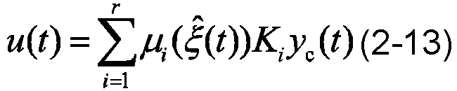
- In formula (2-13) Ki is an output feedback gain to be determined in the i-th local model, and yc (t) represents a compensation output, which is defined as:


- The goal of static output feedback is to control dynamic systems using only knowledge of measurable signals. Therefore, the decision variables are required to depend only on the control input signal u(t), actual output signal y(t), and ultimately rely on measurable state variables. In the case of unmeasurable premise variables, it is still possible to design a stable static output feedback controller. In the structural calculation of the fault-tolerant control law below, both the state derived in the observer and the sensor fault signal estimation are considered.
- Step 52. analyzing the stability of the closed-loop system, wherein the system state estimation error


- By substituting the static output feedback control law (2-13) into the above formula, a conclusion can be drawn as follows:

- Adding and subtracting (
B i -B j )Kjℓx (t), formula (2-17) can be rewritten as:
- In formula (2-18) Fij = Sj +(
B i -B j )Kj ℓ; Aij =(A i -A j )+(B i-B j )Kj (C -ℓ) Therefore, the above LMI constraint formula is equivalent to:
- The entire model is rewritten in a state space representation using the following formula:


- An augmented state vector is defined:

- The following closed loop system is obtained:

- Step 53. The corresponding observer and controller are found to minimize the impact of external disturbance d(t) on the closed-loop system. The emergence of this problem leads to the necessity to solve the standard L2 control under the constraints of linear matrix inequalities provided by the following theorem.
- Lemma 1: Considering two real matrices of appropriate dimensions X, Y as well as F(t), for any scalar δ , the following inequality is proved:

- Lemma 2: If there is a symmetric positive definite matrixP 11, P 12, P 2i, matrixQ 1, Q 2 and positive scalar ψ, and δi , i = 1,... , 7 satisfy the following conditions for i, j = 1, 2,... , r and i ≠ j, the fault-tolerant control system of the forklift anti-rollover sensor based on the singular observer is asymptotically stable.


- Then through the above formula (2-9) Ω and the following formula℘ , the observer gain is obtained.


- Step 54: performing stability verification.
- To obtain non-conservative conditions, the following non-quadratic Lyapunov function is used:

- In the above formula Λ i =diag[P 1 P 2i ], whereinP 1,P 2i are symmetric positive definite matrices. A closed-loop system with fault-tolerant control is stable, and if V̇(xa (t))+eT (t)e(t)-η 2 dT (t)d(t)<0, η can limit the gain L2 from d(t) to e(t). The derivative of Lyapunov function V(xa (t)) is expressed as:

- This condition is negative definite, if


- In formula (2-36);

- Using the
lemma 1 proposed above, there is a positive scalar δi , i = 1,... , 7 let:
- In formula (2-38);

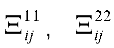
- Applying Schur's complement on BMI items

- For the forklift anti-rollover sensor fault-tolerant system, the above-mentioned effective control strategy is designed so that the forklift anti-rollover system can still ensure a stability of the entire system in case of sensor failure. In this section, numerical simulations are performed to demonstrate the effectiveness and applicability of the proposed method to a forklift anti-rollover sensor fault-tolerant system. The T-S model constructed in the previous article is used to construct an observer, which represents a forklift anti-rollover sensor fault-tolerant system with premise variables that depend on unmeasurable state variables. In the design, the complete vehicle parameters of the forklift considered are shown in the table 1.
Table 1 Parameter Value Vehicle quality (M) 3139 kg Full load quality (m 1) 4639 kg Frame quality (ms ) 2356 kg Distance between front axle and mass center (a) 1 m Distance between rear axle and mass center (b) 0.7 m Distance between front and 1.7 m rear axles (L) Front track (B 1) 1 m Rear track (B 2) 0.97 m Distance between limit block and roll center (l) 0.3 m Height of mass center (h 1) B 2 1 m Height of mass center and roll center (hx ) 0.75 m Front/rear wheel radius (Rf /Rr ) 355 mm/265 mm Moment of inertia of wheels (J) 2 kg·m2 Moment of inertia of vehicle around Z-axis (Iz ) 6129 kg·m2 Moment of inertia of frame around X-axis (Ix ) 3100 kg·m2 Vertical stiffness of front wheel (T 1) 8000 kg·m2 Equivalent contact stiffness (Ks ) 7630 N·M Equivalent contact damping (Cs ) 300 N·m/s Longitudinal speed (vx ) 6m/s Cornering stiffness of front wheel (Cfi ) 145500N/rad Cornering stiffness of rear wheel (Cri ) 145500N/rad - The output behavior of the system affected by fault signals f(t)=(fa (t),fb (t)) T is considered and described as follows:


- For the forklift anti-rollover system, a gyro sensor is used. The gyro sensor can only measure the yaw angular velocity of the forklift. The proposed observer is used to estimate the lateral speed to solve the optimization problem under the linear matrix inequality constraints in the above theorem (2), resulting in the observer and controller gain matrices for the following nominal attenuation levels ψ = 0.843.


- As an embodiment of the present invention,
Fig. 2, Fig. 3 andFig. 4 respectively illustrate the fault fa signals and their estimated value signals, fault fb signals and their estimated value signals, fault-tolerant control input state of the static output feedback.Figs. 5 and 6 respectively show the side slip angle of the forklift body and its estimated value as well as the yaw angular velocity and its estimated value without fault tolerance.Figs. 7 and 8 respectively show the side slip angle of the forklift body and its estimated value as well as yaw angular velocity and its estimated value under fault-tolerant control. - For the case of using the static output feedback fault-tolerant control strategy, it can be noted that when the system sensor fails, despite the system failure and external interference, the forklift anti-rollover system still remains stable. When a fault occurs, the maximum fluctuation of the side slip angle and the yaw angular velocity remains no more than 3% of the maximum angle value without using the static output feedback fault-tolerant control strategy. Therefore, it is shown that the static output feedback fault-tolerant control strategy proposed in this application is effective.
- In another aspect, the present invention also discloses a computer readable storage medium storing a computer program, when the computer program is executed by a processor, the processor performs the steps of any of the above methods.
- In another aspect, the present invention also discloses a computer device, comprising a memory and a processor, wherein the memory stores a computer program, and when the computer program is executed by the processor, the processor performs the steps of any of the above methods.
- In yet another embodiment of this application, a computer program product containing instructions is also provided, when it runs on a computer, the computer performs the steps of any of the methods in the above embodiments.
- It can be understood that the system provided by the embodiments of the present invention corresponds to the method provided by the embodiments of the present invention. For explanations, examples and beneficial effects of relevant content, reference can be made to the corresponding parts of the above method.
- Those of ordinary skill in the art can understand that all or part of the processes in the methods of the above embodiments can be implemented by instructing relevant hardware through computer programs. The programs can be stored in a non-volatile computer-readable storage medium, when the program is executed, it may include the processes of the embodiments of the above-mentioned method. Any reference to memory, storage, database or other media used in the embodiments of this application may include non-volatile and/or volatile memory. Non-volatile memory may include read-only memory (ROM), programmable ROM (PROM), electrically programmable ROM (EPROM), electrically erasable programmable ROM (EEPROM), or flash memory. Volatile memory may include random access memory (RAM) or external cache memory. By way of illustration and not limitation, RAM is available in many forms, such as static RAM (SRAM), dynamic RAM (DRAM), synchronous DRAM (SDRAM), double data rate SDRAM (DDRSDRAM), enhanced SDRAM (ESDRAM), synchronous chain (Synchlink), DRAM (SLDRAM), memory bus (Rambus), direct RAM (RDRAM), direct memory bus dynamic RAM (DRDRAM), and memory bus dynamic RAM (RDRAM), etc.
- The above embodiments are only used to illustrate the technical solutions of the present invention, but not to limit them. Although the present invention has been described in detail with reference to the foregoing embodiments, those of ordinary skill in the art should understand that they can still modify the technical solutions described in the foregoing embodiments, or make equivalent substitutions for some of the technical features. However, these modifications or substitutions do not cause the essence of the corresponding technical solutions to deviate from the spirit and scope of the technical solutions of the respective embodiments of the present invention.
Claims (6)
- A static output feedback control method for forklift stability control, characterized by comprising the following steps:constructing a continuous-time forklift anti-rollover fuzzy system model with formula (1-1):
 using an excitation function ui (ξ(t)) as an input of the system by setting the continuous-time fuzzy system model, and sensor failures and unknown bounded disturbances existing simultaneously;setting a singular observer for estimating a state
 setting a generalized observer for measuring a state of the counterbalanced forklift anti-rollover system in continuous time and performing fault estimation, generating a residual signal L 2 that is as sensitive to faults f(t) as possible and insensitive to disturbances d(t);extending H ∞ control problem to nonlinear situations by setting a residual generator and using the residual signal L 2 for control, observing an minimized interference signal rd (t) to obtain a gain of the residual signal L 2, finding a corresponding positive definite matrix and a positive scalar, and then progressively estimating system state and sensor failures;reconfiguring control laws through the fault and state estimation provided by the above observer, and giving sufficient conditions in form of LMIs to ensure a stability of a resulting closed-loop system.
 - The static output feedback control method for forklift stability control according to claim 1, characterized in that the singular observer is used to simultaneously estimate the state


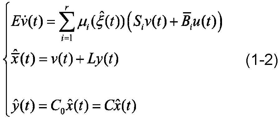

x (t ); ξ̂(t) is an unmeasured premise variable; Si , E , L are observer gains. - The static output feedback control method for forklift stability control according to claim 1, characterized by constructing the generalized observer H(t) ∈ L 2 with formula (1-3), a norm of L 2 is defined as:

- The static output feedback control method for forklift stability control according to claim 1, characterized by constructing a residual generator rd (t) with formula (1-4),

- The static output feedback control method for forklift stability control according to claim 1, characterized by designing the control law of the reconfigured static output feedback controller with formula (1-5):

- A computer readable storage medium storing a computer program, when the computer program is executed by a processor, the processor performs the steps of the method according to any one of claims 1 to 5.
Applications Claiming Priority (2)
| Application Number | Priority Date | Filing Date | Title |
|---|---|---|---|
| CN202210652559.7A CN114967656B (en) | 2022-06-09 | 2022-06-09 | Static output feedback control method for forklift stability control and storage medium |
| PCT/CN2023/096459 WO2023236786A1 (en) | 2022-06-09 | 2023-05-26 | Static output feedback control method for forklift stability control, and storage medium |
Publications (3)
| Publication Number | Publication Date |
|---|---|
| EP4394537A1 true EP4394537A1 (en) | 2024-07-03 |
| EP4394537A4 EP4394537A4 (en) | 2025-03-19 |
| EP4394537B1 EP4394537B1 (en) | 2026-02-25 |
Family
ID=82960863
Family Applications (1)
| Application Number | Title | Priority Date | Filing Date |
|---|---|---|---|
| EP23818951.8A Active EP4394537B1 (en) | 2022-06-09 | 2023-05-26 | Static output feedback control method for forklift stability control, and storage medium |
Country Status (4)
| Country | Link |
|---|---|
| US (1) | US20250004431A1 (en) |
| EP (1) | EP4394537B1 (en) |
| CN (1) | CN114967656B (en) |
| WO (1) | WO2023236786A1 (en) |
Families Citing this family (2)
| Publication number | Priority date | Publication date | Assignee | Title |
|---|---|---|---|---|
| CN114967656B (en) * | 2022-06-09 | 2025-07-25 | 安徽合力股份有限公司 | Static output feedback control method for forklift stability control and storage medium |
| CN118655761B (en) * | 2024-08-16 | 2024-10-25 | 北京科技大学 | Limited slip form fault-tolerant safety control method and device for information physical system |
Family Cites Families (17)
| Publication number | Priority date | Publication date | Assignee | Title |
|---|---|---|---|---|
| TW482129U (en) * | 1997-04-23 | 2002-04-01 | Toyoda Automatic Loom Works | A rock controller for industrial vehicle body |
| JP2000319000A (en) * | 1999-05-12 | 2000-11-21 | Komatsu Ltd | Battery forklift control device |
| US9084076B2 (en) * | 2001-02-16 | 2015-07-14 | Intelligent Technologies International, Inc. | Techniques for obtaining information about objects |
| CN102436179A (en) * | 2011-11-25 | 2012-05-02 | 中国电力科学研究院 | A Robust Fault Detection Filter Design Method for Linear Uncertain Systems |
| CN110161847B (en) * | 2018-09-18 | 2020-12-08 | 南京航空航天大学 | A sensor fault estimation method for UAV formation system based on distributed singular observers |
| US11767008B2 (en) * | 2019-04-29 | 2023-09-26 | Nanjing University Of Aeronautics And Astronautics | Anti-rollover apparatus and control method for heavy-duty vehicles with pneumatic brake system |
| KR102294575B1 (en) * | 2019-12-13 | 2021-08-27 | 한밭대학교 산학협력단 | Sensor fault diagnosis system for converter |
| CN111158343B (en) * | 2020-01-10 | 2023-03-21 | 淮阴工学院 | Asynchronous fault-tolerant control method for switching system with actuator and sensor faults |
| CN111645697B (en) * | 2020-05-23 | 2022-04-15 | 东南大学 | Tank car rollover multistage early warning strategy based on fuzzy logic |
| CN112373461B (en) * | 2020-11-24 | 2022-04-01 | 合肥工业大学 | A kind of anti-rollover control method and control system of a balanced heavy-duty forklift |
| CN113003493B (en) * | 2021-04-25 | 2022-05-06 | 合肥工业大学 | Control system for improving rollover-prevention robustness of counterweight forklift |
| CN113459757B (en) * | 2021-08-20 | 2023-06-30 | 合肥工业大学 | Active fault-tolerant control method of whole vehicle electric control suspension system |
| CN113721468B (en) * | 2021-09-03 | 2023-06-27 | 华东理工大学 | Self-healing control method and system for additive faults of sewage treatment system actuator |
| JP7756532B2 (en) * | 2021-10-01 | 2025-10-20 | 三菱重工業株式会社 | Driving control device, vehicle, driving control method and program |
| CN113885335B (en) * | 2021-11-08 | 2023-04-28 | 江南大学 | Fault-tolerant control method for networked system with partial decoupling disturbance |
| CN114578793B (en) * | 2022-03-21 | 2024-09-13 | 杭州电力设备制造有限公司 | A nonlinear robust fault detection method for generator cars based on observers |
| CN114967656B (en) * | 2022-06-09 | 2025-07-25 | 安徽合力股份有限公司 | Static output feedback control method for forklift stability control and storage medium |
-
2022
- 2022-06-09 CN CN202210652559.7A patent/CN114967656B/en active Active
-
2023
- 2023-05-26 WO PCT/CN2023/096459 patent/WO2023236786A1/en not_active Ceased
- 2023-05-26 US US18/708,212 patent/US20250004431A1/en active Pending
- 2023-05-26 EP EP23818951.8A patent/EP4394537B1/en active Active
Also Published As
| Publication number | Publication date |
|---|---|
| EP4394537B1 (en) | 2026-02-25 |
| EP4394537A4 (en) | 2025-03-19 |
| CN114967656A (en) | 2022-08-30 |
| CN114967656B (en) | 2025-07-25 |
| WO2023236786A1 (en) | 2023-12-14 |
| US20250004431A1 (en) | 2025-01-02 |
Similar Documents
| Publication | Publication Date | Title |
|---|---|---|
| EP4394537B1 (en) | Static output feedback control method for forklift stability control, and storage medium | |
| Yang et al. | A dynamic rollover prediction index of heavy-duty vehicles with a real-time parameter estimation algorithm using NLMS method | |
| US12128893B2 (en) | Intervention-based shared control method and apparatus in forward collision avoidance scenario of autonomous vehicle | |
| Gáspár et al. | The design of an integrated control system in heavy vehicles based on an LPV method | |
| Wang et al. | A robust adaptive fault-tolerant estimator for sideslip angle and tire cornering stiffness with multiple missing data | |
| Yang et al. | A fault estimation and fault-tolerant operation scheme design under simultaneous actuator and sensor faults for steer-by-wire system | |
| Ghani et al. | Continuous–discrete time neural network observer for nonlinear dynamic systems application to vehicle systems | |
| Koysuren et al. | A fault-tolerant model predictive controller with reconfiguration for optimal lateral stability in over-actuated electric vehicles | |
| CN116279508B (en) | Road surface adhesion coefficient estimation method and medium based on rapid convergence SCKF and self-adaptive tire rigidity | |
| Liu et al. | Rollover control of AGV combined with differential drive, active steering, and centroid adjustment under slope driving condition | |
| Zhao et al. | Path tracking fault-tolerant control of intelligent distributed drive electric vehicle based on sliding mode observer | |
| El Messoussi et al. | Four-wheel steering vehicle control using takagi-sugeno fuzzy models | |
| Nair et al. | Prevention of vehicle rollover after wheel lift-off using energy-based controller with proportional gain augmentation | |
| Boukhari et al. | Sensor fault tolerant control strategy for autonomous vehicle driving | |
| Wasim et al. | H-infinity control via scenario optimization for handling and stabilizing vehicle using AFS control | |
| CN117022248A (en) | Heavy truck anti-rollover control methods, devices, equipment and media | |
| Li et al. | Linear time-varying model predictive control for automated vehicles: Feasibility and stability under emergency lane change | |
| Makni et al. | Direct yaw moment Fault Tolerant Tracking Control for lateral vehicle dynamics | |
| Li et al. | Data-enabled predictive control for stability improvement of articulated vehicles | |
| CN114995143B (en) | Adaptive fault-tolerant control method and storage medium for forklift actuator failure | |
| Zhang et al. | Research on active steering control strategy based on sideslip angle estimation for a steering‐by‐wire forklift | |
| Liu et al. | Safe learning reference governor for constrained systems with application to fuel truck rollover avoidance | |
| Boudaoud et al. | Robust Fault Tolerant Control for Highly Automated Vehicle Equipped With Steer-By-Wire System With Multiple Actuator Faults | |
| Suminaka et al. | Adaptable High-Speed Model Predictive Control for Autonomous Drifting: Koopman-Based Dynamics | |
| Guo et al. | A Novel Approach for Integrated Vehicle Dynamics Management Using Improved Adaptive Neural Network |
Legal Events
| Date | Code | Title | Description |
|---|---|---|---|
| STAA | Information on the status of an ep patent application or granted ep patent |
Free format text: STATUS: THE INTERNATIONAL PUBLICATION HAS BEEN MADE |
|
| PUAI | Public reference made under article 153(3) epc to a published international application that has entered the european phase |
Free format text: ORIGINAL CODE: 0009012 |
|
| STAA | Information on the status of an ep patent application or granted ep patent |
Free format text: STATUS: REQUEST FOR EXAMINATION WAS MADE |
|
| 17P | Request for examination filed |
Effective date: 20240328 |
|
| AK | Designated contracting states |
Kind code of ref document: A1 Designated state(s): AL AT BE BG CH CY CZ DE DK EE ES FI FR GB GR HR HU IE IS IT LI LT LU LV MC ME MK MT NL NO PL PT RO RS SE SI SK SM TR |
|
| A4 | Supplementary search report drawn up and despatched |
Effective date: 20250219 |
|
| RIC1 | Information provided on ipc code assigned before grant |
Ipc: G05B 19/042 20060101ALI20250213BHEP Ipc: G05B 13/04 20060101ALI20250213BHEP Ipc: B66F 17/00 20060101ALI20250213BHEP Ipc: G05B 23/02 20060101AFI20250213BHEP |
|
| DAV | Request for validation of the european patent (deleted) | ||
| DAX | Request for extension of the european patent (deleted) | ||
| GRAP | Despatch of communication of intention to grant a patent |
Free format text: ORIGINAL CODE: EPIDOSNIGR1 |
|
| STAA | Information on the status of an ep patent application or granted ep patent |
Free format text: STATUS: GRANT OF PATENT IS INTENDED |
|
| INTG | Intention to grant announced |
Effective date: 20250930 |
|
| GRAS | Grant fee paid |
Free format text: ORIGINAL CODE: EPIDOSNIGR3 |
|
| GRAA | (expected) grant |
Free format text: ORIGINAL CODE: 0009210 |
|
| STAA | Information on the status of an ep patent application or granted ep patent |
Free format text: STATUS: THE PATENT HAS BEEN GRANTED |
|
| AK | Designated contracting states |
Kind code of ref document: B1 Designated state(s): AL AT BE BG CH CY CZ DE DK EE ES FI FR GB GR HR HU IE IS IT LI LT LU LV MC ME MK MT NL NO PL PT RO RS SE SI SK SM TR |
|
| REG | Reference to a national code |
Ref country code: CH Ref legal event code: F10 Free format text: ST27 STATUS EVENT CODE: U-0-0-F10-F00 (AS PROVIDED BY THE NATIONAL OFFICE) Effective date: 20260225 Ref country code: GB Ref legal event code: FG4D |
|
| REG | Reference to a national code |
Ref country code: DE Ref legal event code: R096 Ref document number: 602023012749 Country of ref document: DE |
|
| REG | Reference to a national code |
Ref country code: IE Ref legal event code: FG4D |