EP4394513A1 - Light responsive photoresists and methods - Google Patents
Light responsive photoresists and methods Download PDFInfo
- Publication number
- EP4394513A1 EP4394513A1 EP23196634.2A EP23196634A EP4394513A1 EP 4394513 A1 EP4394513 A1 EP 4394513A1 EP 23196634 A EP23196634 A EP 23196634A EP 4394513 A1 EP4394513 A1 EP 4394513A1
- Authority
- EP
- European Patent Office
- Prior art keywords
- photoresist
- light responsive
- light
- polymer
- wavelengths
- Prior art date
- Legal status (The legal status is an assumption and is not a legal conclusion. Google has not performed a legal analysis and makes no representation as to the accuracy of the status listed.)
- Pending
Links
- 229920002120 photoresistant polymer Polymers 0.000 title claims abstract description 151
- 238000000034 method Methods 0.000 title claims abstract description 75
- 229920000642 polymer Polymers 0.000 claims abstract description 40
- -1 poly(olefin sulfone Chemical class 0.000 claims description 46
- 239000000758 substrate Substances 0.000 claims description 23
- 230000001678 irradiating effect Effects 0.000 claims description 9
- JRZJOMJEPLMPRA-UHFFFAOYSA-N olefin Natural products CCCCCCCC=C JRZJOMJEPLMPRA-UHFFFAOYSA-N 0.000 claims description 8
- 238000010438 heat treatment Methods 0.000 claims description 7
- 125000006657 (C1-C10) hydrocarbyl group Chemical group 0.000 claims description 6
- 238000007747 plating Methods 0.000 claims description 6
- 239000000463 material Substances 0.000 claims description 5
- 230000008569 process Effects 0.000 abstract description 24
- 238000001459 lithography Methods 0.000 abstract description 14
- 238000010586 diagram Methods 0.000 description 13
- 239000012071 phase Substances 0.000 description 12
- 239000000178 monomer Substances 0.000 description 9
- 230000009471 action Effects 0.000 description 8
- 238000007704 wet chemistry method Methods 0.000 description 8
- 125000000217 alkyl group Chemical group 0.000 description 6
- 239000000126 substance Substances 0.000 description 6
- 125000004432 carbon atom Chemical group C* 0.000 description 4
- 230000008859 change Effects 0.000 description 4
- 230000006870 function Effects 0.000 description 4
- 239000007789 gas Substances 0.000 description 4
- 238000012986 modification Methods 0.000 description 4
- 230000004048 modification Effects 0.000 description 4
- RTZKZFJDLAIYFH-UHFFFAOYSA-N Diethyl ether Chemical group CCOCC RTZKZFJDLAIYFH-UHFFFAOYSA-N 0.000 description 3
- 125000003342 alkenyl group Chemical group 0.000 description 3
- 125000000304 alkynyl group Chemical group 0.000 description 3
- 125000003118 aryl group Chemical group 0.000 description 3
- 230000008901 benefit Effects 0.000 description 3
- 125000003917 carbamoyl group Chemical group [H]N([H])C(*)=O 0.000 description 3
- 238000000576 coating method Methods 0.000 description 3
- 230000007812 deficiency Effects 0.000 description 3
- IJGRMHOSHXDMSA-UHFFFAOYSA-N Atomic nitrogen Chemical compound N#N IJGRMHOSHXDMSA-UHFFFAOYSA-N 0.000 description 2
- 239000012988 Dithioester Substances 0.000 description 2
- 125000001931 aliphatic group Chemical group 0.000 description 2
- 125000003710 aryl alkyl group Chemical group 0.000 description 2
- MVPPADPHJFYWMZ-UHFFFAOYSA-N chlorobenzene Chemical compound ClC1=CC=CC=C1 MVPPADPHJFYWMZ-UHFFFAOYSA-N 0.000 description 2
- 150000001875 compounds Chemical class 0.000 description 2
- 125000004122 cyclic group Chemical group 0.000 description 2
- 125000000753 cycloalkyl group Chemical group 0.000 description 2
- ZUOUZKKEUPVFJK-UHFFFAOYSA-N diphenyl Chemical group C1=CC=CC=C1C1=CC=CC=C1 ZUOUZKKEUPVFJK-UHFFFAOYSA-N 0.000 description 2
- 230000005670 electromagnetic radiation Effects 0.000 description 2
- 125000001495 ethyl group Chemical group [H]C([H])([H])C([H])([H])* 0.000 description 2
- 125000001183 hydrocarbyl group Chemical group 0.000 description 2
- PQNFLJBBNBOBRQ-UHFFFAOYSA-N indane Chemical group C1=CC=C2CCCC2=C1 PQNFLJBBNBOBRQ-UHFFFAOYSA-N 0.000 description 2
- 230000007246 mechanism Effects 0.000 description 2
- 125000002496 methyl group Chemical group [H]C([H])([H])* 0.000 description 2
- 239000000203 mixture Substances 0.000 description 2
- 125000001436 propyl group Chemical group [H]C([*])([H])C([H])([H])C([H])([H])[H] 0.000 description 2
- 239000007790 solid phase Substances 0.000 description 2
- 125000000472 sulfonyl group Chemical group *S(*)(=O)=O 0.000 description 2
- 125000000999 tert-butyl group Chemical group [H]C([H])([H])C(*)(C([H])([H])[H])C([H])([H])[H] 0.000 description 2
- CXWXQJXEFPUFDZ-UHFFFAOYSA-N tetralin Chemical group C1=CC=C2CCCCC2=C1 CXWXQJXEFPUFDZ-UHFFFAOYSA-N 0.000 description 2
- 125000003396 thiol group Chemical class [H]S* 0.000 description 2
- 239000012989 trithiocarbonate Substances 0.000 description 2
- 239000012991 xanthate Substances 0.000 description 2
- 125000004973 1-butenyl group Chemical group C(=CCC)* 0.000 description 1
- 125000004972 1-butynyl group Chemical group [H]C([H])([H])C([H])([H])C#C* 0.000 description 1
- 125000006039 1-hexenyl group Chemical group 0.000 description 1
- 125000006023 1-pentenyl group Chemical group 0.000 description 1
- YBYIRNPNPLQARY-UHFFFAOYSA-N 1H-indene Chemical group C1=CC=C2CC=CC2=C1 YBYIRNPNPLQARY-UHFFFAOYSA-N 0.000 description 1
- 125000006069 2,3-dimethyl-2-butenyl group Chemical group 0.000 description 1
- 125000004974 2-butenyl group Chemical group C(C=CC)* 0.000 description 1
- 125000000069 2-butynyl group Chemical group [H]C([H])([H])C#CC([H])([H])* 0.000 description 1
- 125000006040 2-hexenyl group Chemical group 0.000 description 1
- 125000006029 2-methyl-2-butenyl group Chemical group 0.000 description 1
- 125000006024 2-pentenyl group Chemical group 0.000 description 1
- 125000003903 2-propenyl group Chemical group [H]C([*])([H])C([H])=C([H])[H] 0.000 description 1
- 125000006041 3-hexenyl group Chemical group 0.000 description 1
- 125000006027 3-methyl-1-butenyl group Chemical group 0.000 description 1
- UQRONKZLYKUEMO-UHFFFAOYSA-N 4-methyl-1-(2,4,6-trimethylphenyl)pent-4-en-2-one Chemical group CC(=C)CC(=O)Cc1c(C)cc(C)cc1C UQRONKZLYKUEMO-UHFFFAOYSA-N 0.000 description 1
- LFQSCWFLJHTTHZ-UHFFFAOYSA-N Ethanol Chemical compound CCO LFQSCWFLJHTTHZ-UHFFFAOYSA-N 0.000 description 1
- RJUFJBKOKNCXHH-UHFFFAOYSA-N Methyl propionate Chemical group CCC(=O)OC RJUFJBKOKNCXHH-UHFFFAOYSA-N 0.000 description 1
- FXHOOIRPVKKKFG-UHFFFAOYSA-N N,N-Dimethylacetamide Chemical group CN(C)C(C)=O FXHOOIRPVKKKFG-UHFFFAOYSA-N 0.000 description 1
- OAICVXFJPJFONN-UHFFFAOYSA-N Phosphorus Chemical compound [P] OAICVXFJPJFONN-UHFFFAOYSA-N 0.000 description 1
- 229910006074 SO2NH2 Inorganic materials 0.000 description 1
- NINIDFKCEFEMDL-UHFFFAOYSA-N Sulfur Chemical compound [S] NINIDFKCEFEMDL-UHFFFAOYSA-N 0.000 description 1
- UCKMPCXJQFINFW-UHFFFAOYSA-N Sulphide Chemical compound [S-2] UCKMPCXJQFINFW-UHFFFAOYSA-N 0.000 description 1
- XSQUKJJJFZCRTK-UHFFFAOYSA-N Urea Chemical compound NC(N)=O XSQUKJJJFZCRTK-UHFFFAOYSA-N 0.000 description 1
- 125000004423 acyloxy group Chemical group 0.000 description 1
- 125000005073 adamantyl group Chemical group C12(CC3CC(CC(C1)C3)C2)* 0.000 description 1
- 150000001336 alkenes Chemical class 0.000 description 1
- 125000003545 alkoxy group Chemical group 0.000 description 1
- 125000004453 alkoxycarbonyl group Chemical group 0.000 description 1
- 125000003282 alkyl amino group Chemical group 0.000 description 1
- 125000005196 alkyl carbonyloxy group Chemical group 0.000 description 1
- 125000004390 alkyl sulfonyl group Chemical group 0.000 description 1
- 150000001408 amides Chemical class 0.000 description 1
- 125000004397 aminosulfonyl group Chemical group NS(=O)(=O)* 0.000 description 1
- 125000002178 anthracenyl group Chemical group C1(=CC=CC2=CC3=CC=CC=C3C=C12)* 0.000 description 1
- 125000005140 aralkylsulfonyl group Chemical group 0.000 description 1
- 125000001691 aryl alkyl amino group Chemical group 0.000 description 1
- 125000001769 aryl amino group Chemical group 0.000 description 1
- 125000004391 aryl sulfonyl group Chemical group 0.000 description 1
- 125000004104 aryloxy group Chemical group 0.000 description 1
- QVGXLLKOCUKJST-UHFFFAOYSA-N atomic oxygen Chemical compound [O] QVGXLLKOCUKJST-UHFFFAOYSA-N 0.000 description 1
- 125000000751 azo group Chemical group [*]N=N[*] 0.000 description 1
- 125000003828 azulenyl group Chemical group 0.000 description 1
- RWCCWEUUXYIKHB-UHFFFAOYSA-N benzophenone Chemical group C=1C=CC=CC=1C(=O)C1=CC=CC=C1 RWCCWEUUXYIKHB-UHFFFAOYSA-N 0.000 description 1
- 125000001797 benzyl group Chemical group [H]C1=C([H])C([H])=C(C([H])=C1[H])C([H])([H])* 0.000 description 1
- 239000004305 biphenyl Chemical group 0.000 description 1
- 235000010290 biphenyl Nutrition 0.000 description 1
- 125000004106 butoxy group Chemical group [*]OC([H])([H])C([H])([H])C(C([H])([H])[H])([H])[H] 0.000 description 1
- 239000004202 carbamide Substances 0.000 description 1
- 229910052799 carbon Inorganic materials 0.000 description 1
- 125000003178 carboxy group Chemical group [H]OC(*)=O 0.000 description 1
- 150000001732 carboxylic acid derivatives Chemical class 0.000 description 1
- 230000015556 catabolic process Effects 0.000 description 1
- 238000006243 chemical reaction Methods 0.000 description 1
- 229910052801 chlorine Inorganic materials 0.000 description 1
- 125000001309 chloro group Chemical group Cl* 0.000 description 1
- 238000003776 cleavage reaction Methods 0.000 description 1
- 239000011248 coating agent Substances 0.000 description 1
- 238000004590 computer program Methods 0.000 description 1
- 229920001577 copolymer Polymers 0.000 description 1
- 125000004093 cyano group Chemical group *C#N 0.000 description 1
- 125000000392 cycloalkenyl group Chemical group 0.000 description 1
- 125000001995 cyclobutyl group Chemical group [H]C1([H])C([H])([H])C([H])(*)C1([H])[H] 0.000 description 1
- 125000000113 cyclohexyl group Chemical group [H]C1([H])C([H])([H])C([H])([H])C([H])(*)C([H])([H])C1([H])[H] 0.000 description 1
- 125000001511 cyclopentyl group Chemical group [H]C1([H])C([H])([H])C([H])([H])C([H])(*)C1([H])[H] 0.000 description 1
- 125000001559 cyclopropyl group Chemical group [H]C1([H])C([H])([H])C1([H])* 0.000 description 1
- 125000002704 decyl group Chemical group [H]C([H])([H])C([H])([H])C([H])([H])C([H])([H])C([H])([H])C([H])([H])C([H])([H])C([H])([H])C([H])([H])C([H])([H])* 0.000 description 1
- 238000006731 degradation reaction Methods 0.000 description 1
- 238000009792 diffusion process Methods 0.000 description 1
- USIUVYZYUHIAEV-UHFFFAOYSA-N diphenyl ether Chemical group C=1C=CC=CC=1OC1=CC=CC=C1 USIUVYZYUHIAEV-UHFFFAOYSA-N 0.000 description 1
- 125000006575 electron-withdrawing group Chemical group 0.000 description 1
- 238000005516 engineering process Methods 0.000 description 1
- 150000002148 esters Chemical class 0.000 description 1
- 125000003983 fluorenyl group Chemical group C1(=CC=CC=2C3=CC=CC=C3CC12)* 0.000 description 1
- 125000000524 functional group Chemical group 0.000 description 1
- 125000001188 haloalkyl group Chemical group 0.000 description 1
- 125000005843 halogen group Chemical group 0.000 description 1
- 125000003187 heptyl group Chemical group [H]C([*])([H])C([H])([H])C([H])([H])C([H])([H])C([H])([H])C([H])([H])C([H])([H])[H] 0.000 description 1
- 125000004404 heteroalkyl group Chemical group 0.000 description 1
- 125000005842 heteroatom Chemical group 0.000 description 1
- 125000004051 hexyl group Chemical group [H]C([H])([H])C([H])([H])C([H])([H])C([H])([H])C([H])([H])C([H])([H])* 0.000 description 1
- 229920001519 homopolymer Polymers 0.000 description 1
- 125000004435 hydrogen atom Chemical group [H]* 0.000 description 1
- 230000003116 impacting effect Effects 0.000 description 1
- 125000003454 indenyl group Chemical group C1(C=CC2=CC=CC=C12)* 0.000 description 1
- 125000000959 isobutyl group Chemical group [H]C([H])([H])C([H])(C([H])([H])[H])C([H])([H])* 0.000 description 1
- 125000005468 isobutylenyl group Chemical group 0.000 description 1
- 239000012948 isocyanate Substances 0.000 description 1
- 150000002513 isocyanates Chemical class 0.000 description 1
- 125000004491 isohexyl group Chemical group C(CCC(C)C)* 0.000 description 1
- 125000001449 isopropyl group Chemical group [H]C([H])([H])C([H])(*)C([H])([H])[H] 0.000 description 1
- 150000002540 isothiocyanates Chemical class 0.000 description 1
- 230000002045 lasting effect Effects 0.000 description 1
- 229920002521 macromolecule Polymers 0.000 description 1
- 125000002950 monocyclic group Chemical group 0.000 description 1
- 125000004108 n-butyl group Chemical group [H]C([H])([H])C([H])([H])C([H])([H])C([H])([H])* 0.000 description 1
- 125000001624 naphthyl group Chemical group 0.000 description 1
- 150000002825 nitriles Chemical class 0.000 description 1
- 125000000449 nitro group Chemical group [O-][N+](*)=O 0.000 description 1
- 229910052757 nitrogen Inorganic materials 0.000 description 1
- 125000001400 nonyl group Chemical group [H]C([*])([H])C([H])([H])C([H])([H])C([H])([H])C([H])([H])C([H])([H])C([H])([H])C([H])([H])C([H])([H])[H] 0.000 description 1
- 125000002347 octyl group Chemical group [H]C([*])([H])C([H])([H])C([H])([H])C([H])([H])C([H])([H])C([H])([H])C([H])([H])C([H])([H])[H] 0.000 description 1
- 125000004043 oxo group Chemical group O=* 0.000 description 1
- 239000001301 oxygen Substances 0.000 description 1
- 229910052760 oxygen Inorganic materials 0.000 description 1
- 238000000059 patterning Methods 0.000 description 1
- 125000001147 pentyl group Chemical group C(CCCC)* 0.000 description 1
- 125000001792 phenanthrenyl group Chemical group C1(=CC=CC=2C3=CC=CC=C3C=CC12)* 0.000 description 1
- 125000001997 phenyl group Chemical group [H]C1=C([H])C([H])=C(*)C([H])=C1[H] 0.000 description 1
- 150000004713 phosphodiesters Chemical class 0.000 description 1
- 229910052698 phosphorus Inorganic materials 0.000 description 1
- 239000011574 phosphorus Substances 0.000 description 1
- 238000006116 polymerization reaction Methods 0.000 description 1
- 125000002568 propynyl group Chemical group [*]C#CC([H])([H])[H] 0.000 description 1
- 238000010526 radical polymerization reaction Methods 0.000 description 1
- 150000003254 radicals Chemical class 0.000 description 1
- 230000007017 scission Effects 0.000 description 1
- 230000035945 sensitivity Effects 0.000 description 1
- 125000001424 substituent group Chemical group 0.000 description 1
- 125000003107 substituted aryl group Chemical group 0.000 description 1
- 125000005420 sulfonamido group Chemical group S(=O)(=O)(N*)* 0.000 description 1
- 150000003457 sulfones Chemical class 0.000 description 1
- 150000003462 sulfoxides Chemical class 0.000 description 1
- 239000011593 sulfur Substances 0.000 description 1
- 229910052717 sulfur Inorganic materials 0.000 description 1
- 239000013077 target material Substances 0.000 description 1
- 150000003512 tertiary amines Chemical class 0.000 description 1
- 150000003568 thioethers Chemical class 0.000 description 1
- 125000003944 tolyl group Chemical group 0.000 description 1
- 230000001960 triggered effect Effects 0.000 description 1
- 125000000391 vinyl group Chemical group [H]C([*])=C([H])[H] 0.000 description 1
- 229920002554 vinyl polymer Polymers 0.000 description 1
- 125000005023 xylyl group Chemical group 0.000 description 1
Images

Classifications
-
- G—PHYSICS
- G03—PHOTOGRAPHY; CINEMATOGRAPHY; ANALOGOUS TECHNIQUES USING WAVES OTHER THAN OPTICAL WAVES; ELECTROGRAPHY; HOLOGRAPHY
- G03F—PHOTOMECHANICAL PRODUCTION OF TEXTURED OR PATTERNED SURFACES, e.g. FOR PRINTING, FOR PROCESSING OF SEMICONDUCTOR DEVICES; MATERIALS THEREFOR; ORIGINALS THEREFOR; APPARATUS SPECIALLY ADAPTED THEREFOR
- G03F7/00—Photomechanical, e.g. photolithographic, production of textured or patterned surfaces, e.g. printing surfaces; Materials therefor, e.g. comprising photoresists; Apparatus specially adapted therefor
- G03F7/16—Coating processes; Apparatus therefor
- G03F7/168—Finishing the coated layer, e.g. drying, baking, soaking
-
- C—CHEMISTRY; METALLURGY
- C08—ORGANIC MACROMOLECULAR COMPOUNDS; THEIR PREPARATION OR CHEMICAL WORKING-UP; COMPOSITIONS BASED THEREON
- C08G—MACROMOLECULAR COMPOUNDS OBTAINED OTHERWISE THAN BY REACTIONS ONLY INVOLVING UNSATURATED CARBON-TO-CARBON BONDS
- C08G75/00—Macromolecular compounds obtained by reactions forming a linkage containing sulfur with or without nitrogen, oxygen, or carbon in the main chain of the macromolecule
- C08G75/20—Polysulfones
-
- G—PHYSICS
- G03—PHOTOGRAPHY; CINEMATOGRAPHY; ANALOGOUS TECHNIQUES USING WAVES OTHER THAN OPTICAL WAVES; ELECTROGRAPHY; HOLOGRAPHY
- G03F—PHOTOMECHANICAL PRODUCTION OF TEXTURED OR PATTERNED SURFACES, e.g. FOR PRINTING, FOR PROCESSING OF SEMICONDUCTOR DEVICES; MATERIALS THEREFOR; ORIGINALS THEREFOR; APPARATUS SPECIALLY ADAPTED THEREFOR
- G03F7/00—Photomechanical, e.g. photolithographic, production of textured or patterned surfaces, e.g. printing surfaces; Materials therefor, e.g. comprising photoresists; Apparatus specially adapted therefor
- G03F7/004—Photosensitive materials
- G03F7/038—Macromolecular compounds which are rendered insoluble or differentially wettable
-
- G—PHYSICS
- G03—PHOTOGRAPHY; CINEMATOGRAPHY; ANALOGOUS TECHNIQUES USING WAVES OTHER THAN OPTICAL WAVES; ELECTROGRAPHY; HOLOGRAPHY
- G03F—PHOTOMECHANICAL PRODUCTION OF TEXTURED OR PATTERNED SURFACES, e.g. FOR PRINTING, FOR PROCESSING OF SEMICONDUCTOR DEVICES; MATERIALS THEREFOR; ORIGINALS THEREFOR; APPARATUS SPECIALLY ADAPTED THEREFOR
- G03F7/00—Photomechanical, e.g. photolithographic, production of textured or patterned surfaces, e.g. printing surfaces; Materials therefor, e.g. comprising photoresists; Apparatus specially adapted therefor
- G03F7/004—Photosensitive materials
- G03F7/039—Macromolecular compounds which are photodegradable, e.g. positive electron resists
-
- G—PHYSICS
- G03—PHOTOGRAPHY; CINEMATOGRAPHY; ANALOGOUS TECHNIQUES USING WAVES OTHER THAN OPTICAL WAVES; ELECTROGRAPHY; HOLOGRAPHY
- G03F—PHOTOMECHANICAL PRODUCTION OF TEXTURED OR PATTERNED SURFACES, e.g. FOR PRINTING, FOR PROCESSING OF SEMICONDUCTOR DEVICES; MATERIALS THEREFOR; ORIGINALS THEREFOR; APPARATUS SPECIALLY ADAPTED THEREFOR
- G03F7/00—Photomechanical, e.g. photolithographic, production of textured or patterned surfaces, e.g. printing surfaces; Materials therefor, e.g. comprising photoresists; Apparatus specially adapted therefor
- G03F7/26—Processing photosensitive materials; Apparatus therefor
- G03F7/38—Treatment before imagewise removal, e.g. prebaking
-
- G—PHYSICS
- G03—PHOTOGRAPHY; CINEMATOGRAPHY; ANALOGOUS TECHNIQUES USING WAVES OTHER THAN OPTICAL WAVES; ELECTROGRAPHY; HOLOGRAPHY
- G03F—PHOTOMECHANICAL PRODUCTION OF TEXTURED OR PATTERNED SURFACES, e.g. FOR PRINTING, FOR PROCESSING OF SEMICONDUCTOR DEVICES; MATERIALS THEREFOR; ORIGINALS THEREFOR; APPARATUS SPECIALLY ADAPTED THEREFOR
- G03F7/00—Photomechanical, e.g. photolithographic, production of textured or patterned surfaces, e.g. printing surfaces; Materials therefor, e.g. comprising photoresists; Apparatus specially adapted therefor
- G03F7/26—Processing photosensitive materials; Apparatus therefor
- G03F7/40—Treatment after imagewise removal, e.g. baking
-
- G—PHYSICS
- G03—PHOTOGRAPHY; CINEMATOGRAPHY; ANALOGOUS TECHNIQUES USING WAVES OTHER THAN OPTICAL WAVES; ELECTROGRAPHY; HOLOGRAPHY
- G03F—PHOTOMECHANICAL PRODUCTION OF TEXTURED OR PATTERNED SURFACES, e.g. FOR PRINTING, FOR PROCESSING OF SEMICONDUCTOR DEVICES; MATERIALS THEREFOR; ORIGINALS THEREFOR; APPARATUS SPECIALLY ADAPTED THEREFOR
- G03F7/00—Photomechanical, e.g. photolithographic, production of textured or patterned surfaces, e.g. printing surfaces; Materials therefor, e.g. comprising photoresists; Apparatus specially adapted therefor
- G03F7/004—Photosensitive materials
- G03F7/09—Photosensitive materials characterised by structural details, e.g. supports, auxiliary layers
- G03F7/095—Photosensitive materials characterised by structural details, e.g. supports, auxiliary layers having more than one photosensitive layer
Definitions
- This disclosure generally relates to light responsive photoresists, more particularly, to light responsive poly(olefin sulfone) photoresists for dry development and dry stripping.
- Photoresists are used in a number of applications, and include polymer coatings, which undergo a change in solubility when exposed to one or more wavelengths of light. Due to this change in solubility, photoresists are capable of transferring a pattern to a substrate material using a light mask. Due to this feature, photoresists play an important role in lithography.
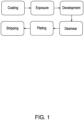
- FIG. 1 A flow chart of a typical lithography process is depicted at FIG. 1 .
- the development and stripping phases of FIG. 1 typically require wet chemistries, which can make these phases difficult, time-consuming, harmful to the environment, or a combination thereof.
- photoresists usually are developed after exposure using a wet chemistry process, in which a developer solution is placed on the photoresist to dissolve the areas of increased solubility.
- This development process also usually involves transfer of the sample from an exposure tool to a developer tool.
- samples typically must be transferred to a tool equipped with stripping solutions to remove the remaining photoresist.
- the methods include providing a substrate having a surface at least partially coated with a light responsive photoresist; cleaving a first portion of the light responsive photoresist by irradiating the first portion of the light responsive photoresist with light of one or more wavelengths effective to cleave the first portion light responsive photoresist; removing the first portion of the light responsive photoresist by vacuum; optionally subjecting the substrate to desmearing; plating the substrate with one or more materials; cleaving the second portion of the light responsive photoresist by (i) heating the second portion of the light responsive photoresist at a temperature and for a time effective to cleave the second portion of the light responsive photoresist, (ii) irradiating the second portion of the light responsive photoresist with light of one or more wavelengths effective to cleave the second portion light responsive photoresist, or (iii) a combination thereof; and removing the second portion of the light responsive photoresist.
- a photoresist may be coated directly on and in contact with a surface of a substrate, on a layer pre-disposed on the substrate, or a combination thereof.
- a light responsive photoresist, prior to cleaving may be in a solid phase at room temperature and atmospheric pressure, or the conditions under which a lithography process is performed.
- a light responsive photoresist, after cleaving is in a gas phase at room temperature and atmospheric pressure, or the conditions under which a lithography process is performed.
- two actions occur “simultaneously” when the two actions are concurrent at any point. For example, two actions, each lasting 10 seconds, occur “simultaneously” when the two actions begin at 0 seconds and end at 10 seconds; or when the first of the two actions begins at 0 seconds, and the second of the two actions begins less than 10 seconds later.
- the removing of a light responsive photoresist after cleaving may be achieved by any known technique.
- the removing of a light responsive photoresist includes applying vacuum, heat, or a combination thereof.
- the removing of a cleaved photoresist may include an active action (e.g., applying vacuum and/or heat), a passive action (e.g., removing a substrate from an enclosure, such as a vacuum oven, and permitting a cleaved photoresist in the gas phase to diffuse), or a combination thereof.
- a light responsive photoresist includes a polymer.
- the polymer may include a plurality of side chains that include a photocleavable group.
- the light responsive photoresist includes a poly(olefin sulfone) that includes a side chain featuring a photocleavable group.
- the photocleavable groups may be dispersed throughout a polymer, e.g., at random intervals along the backbone of a polymer, thereby facilitating cleavage of the polymer at or near each location of an irradiated photocleavable group. Therefore, in some embodiments, the cleaving may "depolymerize" the polymer, as depicted, for example, at FIG. 2 .
- the depolymerization may result in depolymerization products having a volatility that facilitates their removal by vacuum and/or passive diffusion, thereby eliminating the need for wet chemistries during the development or stripping phases.
- polymer refers to a compound formed by two or more monomers of the same or different type that are covalently bonded to each other; therefore, the term “polymer” refers to and includes homopolymers, copolymers, oligomers, etc. having any arrangement, e.g., straight, branched, crosslinked, star, comb, etc.
- the polymer may have any molecular weight that does not undesirably impact the process in which the light responsive photoresist is used.
- the polymer has a weight average molecular weight (Mw) of about 50,000 g/mol to about 1,000,000 g/mol, about 100,000 g/mol to about 1,000,000 g/mol, about 100,000 g/mol to about 750,000 g/mol, or about 100,000 g/mol to about 500,000 g/mol.
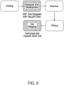
- some embodiments of the photoresists herein fundamentally differ from conventional photoresists, because those herein can undergo a change in state (e.g., from a solid phase to a gas phase), instead of a change in solubility upon exposure to light or elevated temperatures. Due at least to this difference the process flow of lithography processes that use embodiments of the light responsive photoresists provided herein are not required to include wet chemistry steps during development and/or stripping, as depicted at FIG. 3 .
- the "Exposure and Development" process of FIG. 3 may be performed, at least in part, with an exposure tool equipped with a vacuum oven.
- the vacuum oven may facilitate, or assist, the removal of the cleaved photoresist.
- the "Dry Stripping" process of FIG. 3 may be performed with a vacuum oven tool, which, again, may facilitate, or assist, the removal of the cleaved photoresist.
- the poly(olefin sulfone) may be produced from the alternating radical polymerization of SO 2 units, an alkene, and a third comonomer that includes a photocleavable group.
- the third comonomer is an olefin-functionalized photo-radical generator, as depicted in the following scheme.
- the photo-labile groups (R 2 ) may be randomly distributed throughout the polymer backbone. Subsequent irradiation with one or more wavelengths of light specific to the photo-radical generator (R 2 ) may trigger depolymerization of the polymer, which may occur according the mechanism depicted at the following scheme.
- the following scheme depicts a polymer of formula (Ia) (see below), but other polymers of formula (I) may proceed according to the depicted mechanism:
- the light responsive photoresist includes a polymer of formula (I): wherein n is 1 to 10,000; wherein m is 1 to 10,000; wherein R 1 is a C 1 -C 10 hydrocarbyl; and wherein R 2 is a photocleavable group. R 1 may not include an electron withdrawing group.
- R 2 is a photocleavable group of formula (II) - wherein R 3 is selected from the group consisting of - and wherein z is 1 to 11.
- the photocleavable group, R 2 is selected from the group consisting of -
- the comonomers that include the photocleavable group, R 2 may be formed by any known technique.
- the comonomers are produced according to the reactions depicted in the following scheme, which can be modified to produce each of the embodiments described herein:
- the light responsive photoresist includes a polymer of formula (Ib): wherein x is 1 to 4. wherein n is 1 to 10,000; wherein m is 1 to 10,000; and wherein R 2 is a photocleavable group.
- R 2 of formula (lb) is a photocleavable group of formula (II) - wherein R 3 is selected from the group consisting of - and , wherein z is 1 to 11.
- the photocleavable group of formula (Ib) is selected from the group consisting of -
- aliphatic groups include, but are not limited to, an alkyl group, a cycloalkyl group, an alkenyl group, a cycloalkenyl group, an alkynyl group, an alkadienyl group, a cyclic group, and the like, and includes all substituted, unsubstituted, branched, and linear analogs or derivatives thereof, in each instance having 1 to about 10 carbon atoms.
- alkyl groups include, but are not limited to, methyl, ethyl, propyl, isopropyl, n-butyl, t-butyl, isobutyl, pentyl, hexyl, isohexyl, heptyl, 4,4-dimethylpentyl, octyl, 2,2,4-trimethylpentyl, nonyl, and decyl.
- Cycloalkyl moieties may be monocyclic or multicyclic, and examples include cyclopropyl, cyclobutyl, cyclopentyl, cyclohexyl, and adamantyl.
- aryl or arylalkyl moieties include, but are not limited to, anthracenyl, azulenyl, biphenyl, fluorenyl, indan, indenyl, naphthyl, phenanthrenyl, phenyl, 1,2,3,4-tetrahydro-naphthalene, tolyl, xylyl, mesityl, benzyl, and the like, including any heteroatom substituted derivative thereof.
- the term "about” means plus or minus 10 % of the numerical value of the number with which it is being used.
- Example 2 may include the method of example 1 and/or any other example herein, wherein the cleaving of the at least a portion of the light responsive photoresist and the removing of the cleaved photoresist occur simultaneously.
- Example 6 may include the method of example 5 and/or any other example herein, wherein the cleaving of the at least a portion of the light responsive photoresist depolymerizes the polymer.
- Example 7 may include the method of example 5 and/or any other example herein, wherein the light responsive photoresist comprises a poly(olefin sulfone) comprising one or more photocleavable groups.
- Example 8 may include the method of example 7 and/or any other example herein, wherein the photoresist comprises a polymer of the following formula:
- Example 12 may include the method of example 1 and/or any other example herein, wherein the light of one or more wavelengths consists of light of two or more wavelengths within a range of about 10 nm.
- Example 14 may include the method of example 13 and/or any other example herein, wherein the cleaving and the removing of the second portion of the light responsive photoresist occur simultaneously.
- Example 17 may include the method of example 16 and/or any other example herein, wherein the photoresist comprises a polymer of the following formula:
- Example 19 may include the method of example 17 and/or any other example herein, wherein the photoresist comprises a polymer of the following formula: wherein x is 1 to 4.
- blocks of the block diagrams and flow diagrams support combinations of means for performing the specified functions, combinations of elements or steps for performing the specified functions and program instruction means for performing the specified functions. It will also be understood that each block of the block diagrams and flow diagrams, and combinations of blocks in the block diagrams and flow diagrams, may be implemented by special-purpose, hardware-based computer systems that perform the specified functions, elements or steps, or combinations of special-purpose hardware and computer instructions.
- conditional language such as, among others, “can,” “could,” “might,” or “may,” unless specifically stated otherwise, or otherwise understood within the context as used, is generally intended to convey that certain implementations could include, while other implementations do not include, certain features, elements, and/or operations. Thus, such conditional language is not generally intended to imply that features, elements, and/or operations are in any way required for one or more implementations or that one or more implementations necessarily include logic for deciding, with or without user input or prompting, whether these features, elements, and/or operations are included or are to be performed in any particular implementation.
Landscapes
- Physics & Mathematics (AREA)
- General Physics & Mathematics (AREA)
- Spectroscopy & Molecular Physics (AREA)
- Chemical & Material Sciences (AREA)
- Health & Medical Sciences (AREA)
- Chemical Kinetics & Catalysis (AREA)
- Medicinal Chemistry (AREA)
- Polymers & Plastics (AREA)
- Organic Chemistry (AREA)
- Exposure And Positioning Against Photoresist Photosensitive Materials (AREA)
- Addition Polymer Or Copolymer, Post-Treatments, Or Chemical Modifications (AREA)
Abstract
Light responsive photoresists, and methods of using light responsive photoresists in processes, such as lithography processes. The light responsive photoresists may include a polymer featuring a photocleavable group. Due to the photocleavable group, the polymer may depolymerize when irradiated with one or more wavelengths of light. The depolymerized products may be in the gas phase.
Description
- This disclosure generally relates to light responsive photoresists, more particularly, to light responsive poly(olefin sulfone) photoresists for dry development and dry stripping.
- Photoresists are used in a number of applications, and include polymer coatings, which undergo a change in solubility when exposed to one or more wavelengths of light. Due to this change in solubility, photoresists are capable of transferring a pattern to a substrate material using a light mask. Due to this feature, photoresists play an important role in lithography.
- Typically, photoresists are used in processes that may include applying a photoresist to a surface during a coating process, exposing the photoresist to one or more wavelengths of light to imprint a pattern, development to remove soluble areas, plating to buildup target material in the revealed pattern, and stripping to remove the remaining photoresist.
- A flow chart of a typical lithography process is depicted at
FIG. 1 . The development and stripping phases ofFIG. 1 typically require wet chemistries, which can make these phases difficult, time-consuming, harmful to the environment, or a combination thereof. For example, photoresists usually are developed after exposure using a wet chemistry process, in which a developer solution is placed on the photoresist to dissolve the areas of increased solubility. This development process also usually involves transfer of the sample from an exposure tool to a developer tool. Similarly, after plating, samples typically must be transferred to a tool equipped with stripping solutions to remove the remaining photoresist. - As the industries that use lithography seek out more "green chemistry" processes, there is an increasing need to develop solvent-less processes.
- There remains a need for improved photoresists and lithography methods, which reduce or eliminate a reliance on wet chemistries, including during the development and/or stripping phases.
-
-
FIG. 1 depicts a flow chart of a typical lithography process. -
FIG. 2 depicts a schematic of an embodiment of a light responsive photoresist, and an embodiment of a photo-triggered depolymerization sequence. -
FIG. 3 depicts a flow chart of an embodiment of a lithography process that includes the use of an embodiment of a depolymerizable photoresist. - Certain implementations will now be described more fully below with reference to the accompanying drawings, in which various implementations and/or aspects are shown. However, various aspects may be implemented in many different forms and should not be construed as limited to the implementations set forth herein; rather, these implementations are provided so that this disclosure will be thorough and complete, and will fully convey the scope of the disclosure to those skilled in the art. Like numbers in the figures refer to like elements throughout. Hence, if a feature is used across several drawings, the number used to identify the feature in the drawing where the feature first appeared will be used in later drawings.
- The following description and the drawings sufficiently illustrate specific embodiments to enable those skilled in the art to practice them. Other embodiments may incorporate structural, logical, process, algorithm, and other changes. Portions and features of some embodiments may be included in, or substituted for, those of other embodiments. Embodiments set forth in the claims encompass all available equivalents of those claims.
- Provided herein are photoresists and methods of removing photoresists, including lithography processes, which may eliminate the need for wet chemistries in the development phase, the stripping phase, or both the development phase and the stripping phase. By eliminating the use of wet chemistry in one or more phases of a lithography process, the photoresists and methods herein may establish or contribute to a green chemistry process flow. Additionally or alternatively, the photoresists and methods herein may reduce the cost of lithography processes by eliminating the need for wet chemistry enabled tools dedicated to developing and/or stripping photoresists.
- In some embodiments, the methods include providing a substrate having a surface at least partially coated with a light responsive photoresist; cleaving at least a portion of the light responsive photoresist to form a cleaved photoresist; and removing the cleaved photoresist from the substrate. The cleaving and the removing of the cleaved photoresist may occur simultaneously. The substrate that is at least partially coated with a light responsive photoresist may be provided after any step of a lithography process, such as after a coating step, or after a plating step. Therefore, the cleaving of at least a portion of the light responsive photoresist may be performed as (or as part of) a development step and/or a stripping step. The cleaving may be achieved by (i) irradiating the at least a portion of the light responsive photoresist with light of one or more wavelengths effective to cleave the light responsive photoresist, (ii) heating the at least a portion of the light responsive photoresist at a temperature and for a time effective to cleave the light responsive photoresist, or (iii) a combination thereof. Due to the ability to remove the light responsive photoresist through non-specific thermal degradation with simple heating under vacuum, embodiments of the methods herein may be used to rework samples. For example, if metrology shows a poor patterning result after exposure, the sample can be heated or irradiated under vacuum to remove the light responsive photoresist gently, without undesirably impacting the sample underneath, thereby allowing a substrate, such as a panel or wafer, to be reused instead of scrapped. This possibility represents a distinct advantage over conventional photoresist materials, which require a wet chemical stripping process to clean a sample effectively.
- In some embodiments, the methods include providing a substrate having a surface at least partially coated with a light responsive photoresist; cleaving a first portion of the light responsive photoresist by irradiating the first portion of the light responsive photoresist with light of one or more wavelengths effective to cleave the first portion light responsive photoresist; removing the first portion of the light responsive photoresist by vacuum; optionally subjecting the substrate to desmearing; plating the substrate with one or more materials; cleaving the second portion of the light responsive photoresist by (i) heating the second portion of the light responsive photoresist at a temperature and for a time effective to cleave the second portion of the light responsive photoresist, (ii) irradiating the second portion of the light responsive photoresist with light of one or more wavelengths effective to cleave the second portion light responsive photoresist, or (iii) a combination thereof; and removing the second portion of the light responsive photoresist.
- A photoresist may be coated directly on and in contact with a surface of a substrate, on a layer pre-disposed on the substrate, or a combination thereof.
- As used herein, the phrase "light responsive photoresist" refers to a photoresist having a chemical structure that can be cleaved (e.g., by breaking of a covalent bond) at one or more locations of the chemical structure upon and/or after irradiation with one or more wavelengths of electromagnetic radiation (e.g., light) and/or exposure to an increased temperature.
- A light responsive photoresist, prior to cleaving, may be in a solid phase at room temperature and atmospheric pressure, or the conditions under which a lithography process is performed. In some embodiments, a light responsive photoresist, after cleaving, is in a gas phase at room temperature and atmospheric pressure, or the conditions under which a lithography process is performed.
- One or more specific wavelengths of light may cleave a light responsive photoresist, due to the presence of the photocleavable groups. The photocleavable groups may be selected based on the one or more wavelengths of light a user wishes to employ during any of the methods herein. The light of one or more wavelengths may consist of light of one wavelength, such as 365 nm, or 450 nm. The light of one or more wavelengths may consist of light of two or more wavelengths within a range of about 10 nm. For example, the light of one or more wavelengths may consist of light having two or more wavelengths of from about 360 nm to about 370 nm, or from about 445 nm to about 455 nm. Additionally or alternatively, elevated temperatures may cleave a light responsive photoresist. The use of elevated temperatures, therefore, may be used to remove any residual light responsive photoresist during stripping.
- As used herein, the phrase "photocleavable group" refers to a photo-labile substituent that can be removed from a compound or macromolecule, e.g., a polymer, upon irradiation with one or more wavelengths of electromagnetic radiation (e.g., light) and/or exposure to an increased temperature, wherein the removal of the photocleavable group may generate a radical (see, e.g., Scheme 2). Therefore, a monomer that includes a photocleavable group may be a photo-radical generator co-monomer.
- A photo-radical generator co-monomer may be tuned to control or modify the wavelength sensitivity of a light responsive photoresist. For example, a photo-radical generator co-monomer may include moieties, such as trithiocarbonates, xanthates, or aryl dithioesters. These examples of photo-radical generator co-monomers can respond to different wavelengths, with aryl dithioesters being most active at about 365 nm, xanthates at about 385 nm, and trithiocarbonates at about 450 nm. Within each of these three photo-sensitive co-monomer classes, structural changes can be utilized to further tune the target wavelength or polymer properties.
- The cleaving of the first portion of the light responsive photoresist and the removing of the first portion of the light responsive photoresist may occur simultaneously. The cleaving of the second portion of the light responsive photoresist and the removing of the second portion of the light responsive photoresist may occur simultaneously.
- As used herein, two actions occur "simultaneously" when the two actions are concurrent at any point. For example, two actions, each lasting 10 seconds, occur "simultaneously" when the two actions begin at 0 seconds and end at 10 seconds; or when the first of the two actions begins at 0 seconds, and the second of the two actions begins less than 10 seconds later.
- The removing of a light responsive photoresist after cleaving may be achieved by any known technique. In some embodiments, the removing of a light responsive photoresist includes applying vacuum, heat, or a combination thereof. The removing of a cleaved photoresist may include an active action (e.g., applying vacuum and/or heat), a passive action (e.g., removing a substrate from an enclosure, such as a vacuum oven, and permitting a cleaved photoresist in the gas phase to diffuse), or a combination thereof.
- In some embodiments, a light responsive photoresist includes a polymer. The polymer may include a plurality of side chains that include a photocleavable group. In some embodiments, the light responsive photoresist includes a poly(olefin sulfone) that includes a side chain featuring a photocleavable group. The photocleavable groups may be dispersed throughout a polymer, e.g., at random intervals along the backbone of a polymer, thereby facilitating cleavage of the polymer at or near each location of an irradiated photocleavable group. Therefore, in some embodiments, the cleaving may "depolymerize" the polymer, as depicted, for example, at
FIG. 2 . The depolymerization may result in depolymerization products having a volatility that facilitates their removal by vacuum and/or passive diffusion, thereby eliminating the need for wet chemistries during the development or stripping phases. - As used herein, the term "polymer" refers to a compound formed by two or more monomers of the same or different type that are covalently bonded to each other; therefore, the term "polymer" refers to and includes homopolymers, copolymers, oligomers, etc. having any arrangement, e.g., straight, branched, crosslinked, star, comb, etc.
- When a light responsive photoresist includes a polymer, the polymer may have any molecular weight that does not undesirably impact the process in which the light responsive photoresist is used. In some embodiments, the polymer has a weight average molecular weight (Mw) of about 50,000 g/mol to about 1,000,000 g/mol, about 100,000 g/mol to about 1,000,000 g/mol, about 100,000 g/mol to about 750,000 g/mol, or about 100,000 g/mol to about 500,000 g/mol.
- Due to the depolymerization of some embodiments of the photoresists into volatile depolymerization products, some embodiments of the photoresists herein fundamentally differ from conventional photoresists, because those herein can undergo a change in state (e.g., from a solid phase to a gas phase), instead of a change in solubility upon exposure to light or elevated temperatures. Due at least to this difference the process flow of lithography processes that use embodiments of the light responsive photoresists provided herein are not required to include wet chemistry steps during development and/or stripping, as depicted at
FIG. 3 . The "Exposure and Development" process ofFIG. 3 may be performed, at least in part, with an exposure tool equipped with a vacuum oven. The vacuum oven may facilitate, or assist, the removal of the cleaved photoresist. Similarly, the "Dry Stripping" process ofFIG. 3 may be performed with a vacuum oven tool, which, again, may facilitate, or assist, the removal of the cleaved photoresist. - When the light responsive photoresist includes a poly(olefin sulfones), the poly(olefin sulfone) may be produced from the alternating radical polymerization of SO2 units, an alkene, and a third comonomer that includes a photocleavable group. In some embodiments, the third comonomer is an olefin-functionalized photo-radical generator, as depicted in the following scheme.

- During the polymerization depicted at Scheme 1, the photo-labile groups (R2) may be randomly distributed throughout the polymer backbone. Subsequent irradiation with one or more wavelengths of light specific to the photo-radical generator (R2) may trigger depolymerization of the polymer, which may occur according the mechanism depicted at the following scheme. The following scheme depicts a polymer of formula (Ia) (see below), but other polymers of formula (I) may proceed according to the depicted mechanism:

- In some embodiments, the light responsive photoresist includes a polymer of formula (I):

R2 is a photocleavable group. R1 may not include an electron withdrawing group.
In some embodiments, R2 is a photocleavable group of formula (II) -


R2, is selected from the group consisting of -
- The comonomers that include the photocleavable group, R2, may be formed by any known technique. In some embodiments, the comonomers are produced according to the reactions depicted in the following scheme, which can be modified to produce each of the embodiments described herein:

- In some embodiments, the light responsive photoresist includes a polymer of formula (Ia):


- In some embodiments, the light responsive photoresist includes a polymer of formula (Ib):


- The light responsive photoresists having structures according to formula (I), formula (Ia), or formula (Ib) may include any ratio of "n" to "m". In some embodiments, the ratio of "n" to "m" is about 99:1 to about 50:50, about 99:1 to about 60:40, about 99:1 to about 70:30, about 99:1 to about 80:20, about 99:1 to about 90:10, about 90:10 to about 50:50, about 80:20 to about 50:50, about 70:30 to about 50:50, or about 60:40 to about 50:50.
- The phrases "C1-C10 hydrocarbyl", and the like, as used herein, generally refer to unsubstituted or substituted aliphatic, unsubstituted or substituted aryl, or unsubstituted or substituted arylalkyl groups containing 1 to 10 carbon atoms. Examples of aliphatic groups, in each instance, include, but are not limited to, an alkyl group, a cycloalkyl group, an alkenyl group, a cycloalkenyl group, an alkynyl group, an alkadienyl group, a cyclic group, and the like, and includes all substituted, unsubstituted, branched, and linear analogs or derivatives thereof, in each instance having 1 to about 10 carbon atoms. Examples of alkyl groups include, but are not limited to, methyl, ethyl, propyl, isopropyl, n-butyl, t-butyl, isobutyl, pentyl, hexyl, isohexyl, heptyl, 4,4-dimethylpentyl, octyl, 2,2,4-trimethylpentyl, nonyl, and decyl. Cycloalkyl moieties may be monocyclic or multicyclic, and examples include cyclopropyl, cyclobutyl, cyclopentyl, cyclohexyl, and adamantyl. Additional examples of alkyl moieties have linear, branched and/or cyclic portions (e.g., 1-ethyl-4-methyl-cyclohexyl). Representative alkenyl moieties include vinyl, allyl, 1-butenyl, 2-butenyl, isobutylenyl, 1-pentenyl, 2-pentenyl, 3-methyl-1-butenyl, 2-methyl-2-butenyl, 2,3-dimethyl-2-butenyl, 1-hexenyl, 2-hexenyl, 3-hexenyl, 1-heptenyl, 2-heptenyl, 3-heptenyl, 1-octenyl, 2-octenyl, 3-octenyl, 1-nonenyl, 2-nonenyl, 3-nonenyl, 1-decenyl, 2-decenyl and 3-decenyl. Representative alkynyl moieties include acetylenyl, propynyl, 1-butynyl, 2-butynyl, 1-pentynyl, 2-pentynyl, 3-methyl-1-butynyl, 4-pentynyl, 1-hexynyl, 2-hexynyl, 5-hexynyl, 1-heptynyl, 2-heptynyl, 6-heptynyl, 1-octynyl, 2-octynyl, 7-octynyl, 1-nonynyl, 2-nonynyl, 8-nonynyl, 1-decynyl, 2-decynyl, and 9-decynyl. Examples of aryl or arylalkyl moieties include, but are not limited to, anthracenyl, azulenyl, biphenyl, fluorenyl, indan, indenyl, naphthyl, phenanthrenyl, phenyl, 1,2,3,4-tetrahydro-naphthalene, tolyl, xylyl, mesityl, benzyl, and the like, including any heteroatom substituted derivative thereof.
- Unless otherwise indicated, the term "substituted", when used to describe a chemical structure or moiety, refers to a derivative of that structure or moiety wherein (i) a multi-valent non-carbon atom (e.g., oxygen, nitrogen, sulfur, phosphorus, etc.) is bonded to one or more carbon atoms of the chemical structure or moiety (e.g., a "substituted" C4 hydrocarbyl may include, but is not limited to, diethyl ether moiety, a methyl propionate moiety, an N,N-dimethylacetamide moiety, a butoxy moiety, etc., and a "substituted" aryl C12 hydrocarbyl may include, but is not limited to, an oxydibenzene moiety, a benzophenone moiety, etc.) or (ii) one or more of its hydrogen atoms (e.g., chlorobenzene may be characterized generally as an aryl C6 hydrocarbyl "substituted" with a chlorine atom) is substituted with a chemical moiety or functional group such as alcohol, alkoxy, alkanoyloxy, alkoxycarbonyl, alkenyl, alkyl (e.g., methyl, ethyl, propyl, t-butyl), alkynyl, alkylcarbonyloxy (-OC(O)alkyl), amide (-C(O)NH-alkyl- or -alkylNHC(O)alkyl), tertiary amine (such as alkylamino, arylamino, arylalkylamino), aryl, aryloxy, azo, carbamoyl (-NHC(O)O-alkyl- or -OC(O)NH-alkyl), carbamyl (e.g., CONH2, as well as CONH-alkyl, CONH-aryl, and CONH-arylalkyl), carboxyl, carboxylic acid, cyano, ester, ether (e.g., methoxy, ethoxy), halo, haloalkyl (e.g., -CCl3, -CF3, -C(CF3)3), heteroalkyl, isocyanate, isothiocyanate, nitrile, nitro, oxo, phosphodiester, sulfide, sulfonamido (e.g., SO2NH2), sulfone, sulfonyl (including alkylsulfonyl, arylsulfonyl and arylalkylsulfonyl), sulfoxide, thiol (e.g., sulfhydryl, thioether) or urea (-NHCONH-alkyl-).
- All referenced publications are incorporated herein by reference in their entirety. Furthermore, where a definition or use of a term in a reference, which is incorporated by reference herein, is inconsistent or contrary to the definition of that term provided herein, the definition of that term provided herein applies and the definition of that term in the reference does not apply.
- While certain aspects of conventional technologies have been discussed to facilitate disclosure of various embodiments, applicants in no way disclaim these technical aspects, and it is contemplated that the present disclosure may encompass one or more of the conventional technical aspects discussed herein.
- The present disclosure may address one or more of the problems and deficiencies of known methods and processes. However, it is contemplated that various embodiments may prove useful in addressing other problems and deficiencies in a number of technical areas. Therefore, the present disclosure should not necessarily be construed as limited to addressing any of the particular problems or deficiencies discussed herein.
- In this specification, where a document, act or item of knowledge is referred to or discussed, this reference or discussion is not an admission that the document, act or item of knowledge or any combination thereof was at the priority date, publicly available, known to the public, part of common general knowledge, or otherwise constitutes prior art under the applicable statutory provisions; or is known to be relevant to an attempt to solve any problem with which this specification is concerned.
- In the descriptions provided herein, the terms "includes," "is," "containing," "having," and "comprises" are used in an open-ended fashion, and thus should be interpreted to mean "including, but not limited to." When devices, compositions, or methods are claimed or described in terms of "comprising" various steps or components, the devices, systems, or methods can also "consist essentially of" or "consist of" the various steps or components, unless stated otherwise.
- The terms "a," "an," and "the" are intended to include plural alternatives, e.g., at least one. For instance, the disclosure of "a monomer", "a substrate", and the like, is meant to encompass one, or mixtures or combinations of more than one monomer, substrate, and the like, unless otherwise specified.
- Various numerical ranges may be disclosed herein. When Applicant discloses or claims a range of any type, Applicant's intent is to disclose or claim individually each possible number that such a range could reasonably encompass, including end points of the range as well as any sub-ranges and combinations of sub-ranges encompassed therein, unless otherwise specified. Moreover, all numerical end points of ranges disclosed herein are approximate. As a representative example, Applicant discloses, in some embodiments, that the ratio of "n" to "m" is about 60:40 to about 50:50. This range should be interpreted as encompassing about 60:40 and about 50:50, and about 59:41, about 58:42, about 57:43, about 56:44, about 55:45, about 54:46, about 53:47, about 52:48, and about 51:49, including any ranges and sub-ranges between any of these values.
- As used herein, the term "about" means plus or minus 10 % of the numerical value of the number with which it is being used.
- Many modifications and other implementations of the disclosure set forth herein will be apparent having the benefit of the teachings presented in the foregoing descriptions and the associated drawings. Therefore, it is to be understood that the disclosure is not to be limited to the specific implementations disclosed and that modifications and other implementations are intended to be included within the scope of the appended claims. Although specific terms are employed herein, they are used in a generic and descriptive sense only and not for purposes of limitation.
- The following examples pertain to further embodiments.
- Example 1 may include a method, comprising: providing a substrate having a surface at least partially coated with a light responsive photoresist; cleaving at least a portion of the light responsive photoresist to form a cleaved photoresist by (i) irradiating the at least a portion of the light responsive photoresist with light of one or more wavelengths effective to cleave the light responsive photoresist, (ii) heating the at least a portion of the light responsive photoresist at a temperature and for a time effective to cleave the light responsive photoresist, or (iii) a combination thereof; and removing the cleaved photoresist from the substrate.
- Example 2 may include the method of example 1 and/or any other example herein, wherein the cleaving of the at least a portion of the light responsive photoresist and the removing of the cleaved photoresist occur simultaneously.
- Example 3 may include the method of example 1 and/or any other example herein, wherein the removing of the cleaved photoresist comprises applying vacuum, heat, or a combination thereof.
- Example 4 may include the method of example 1 and/or any other example herein, wherein the cleaved photoresist is a gas.
- Example 5 may include the method of example 1 and/or any other example herein, wherein the light responsive photoresist comprises a polymer, the polymer comprising a plurality of side chains, wherein one or more of the sidechains comprises a photocleavable group.
- Example 6 may include the method of example 5 and/or any other example herein, wherein the cleaving of the at least a portion of the light responsive photoresist depolymerizes the polymer.
- Example 7 may include the method of example 5 and/or any other example herein, wherein the light responsive photoresist comprises a poly(olefin sulfone) comprising one or more photocleavable groups.
- Example 8 may include the method of example 7 and/or any other example herein, wherein the photoresist comprises a polymer of the following formula:

- wherein n is 1 to 10,000;
- wherein m is 1 to 10,000;
- wherein R1 is a C1-C10 hydrocarbyl;
- wherein R2 is a photocleavable group of formula (II) -
- Example 9 may include the method of example 8 and/or any other example herein, wherein the photoresist comprises a polymer of the following formula:

- Example 10 may include the method of example 8 and/or any other example herein, wherein the photoresist comprises a polymer of the following formula:

- Example 11 may include the method of example 1 and/or any other example herein, wherein the light of one or more wavelengths consists of light of one wavelength.
- Example 12 may include the method of example 1 and/or any other example herein, wherein the light of one or more wavelengths consists of light of two or more wavelengths within a range of about 10 nm.
- Example 13 may include a method, comprising: providing a substrate having a surface at least partially coated with a light responsive photoresist; cleaving a first portion of the light responsive photoresist by irradiating the first portion of the light responsive photoresist with light of one or more wavelengths effective to cleave the first portion of the light responsive photoresist; removing the first portion of the light responsive photoresist by vacuum, wherein the cleaving of the first portion of the light responsive photoresist and the removing of the first portion of the light responsive photoresist occur simultaneously; optionally subjecting the substrate to desmearing; plating the substrate with one or more materials; cleaving the second portion of the light responsive photoresist by (i) heating the second portion of the light responsive photoresist at a temperature and for a time effective to cleave the second portion of the light responsive photoresist, (ii) irradiating the second portion of the light responsive photoresist with light of one or more wavelengths effective to cleave the second portion light responsive photoresist, or (iii) a combination thereof; and removing the second portion of the light responsive photoresist.
- Example 14 may include the method of example 13 and/or any other example herein, wherein the cleaving and the removing of the second portion of the light responsive photoresist occur simultaneously.
- Example 15 may include the method of example 13 and/or any other example herein, wherein the light responsive photoresist comprises a polymer, the polymer comprising a plurality of side chains, wherein one or more of the side chains comprises a photocleavable group.
- Example 16 may include the method of example 13 and/or any other example herein, wherein the light responsive photoresist comprises a poly(olefin sulfone) comprises one or more photocleavable groups.
- Example 17 may include the method of example 16 and/or any other example herein, wherein the photoresist comprises a polymer of the following formula:

- wherein n is 1 to 10,000;
- wherein m is 1 to 10,000;
- wherein R1 is a C1-C10 hydrocarbyl;
- wherein R2 is a photocleavable group of formula (II) -
- Example 18 may include the method of example 17 and/or any other example herein, wherein the photoresist comprises a polymer of the following formula:

- Example 19 may include the method of example 17 and/or any other example herein, wherein the photoresist comprises a polymer of the following formula:

- Example 20 may include the method of example 13 and/or any other example herein, wherein the light of one or more wavelengths (i) consists of light of one wavelength, or (ii) consists of light of one or more wavelengths within a range of about 10 nm.
- Certain aspects of the disclosure are described above with reference to block and flow diagrams of systems, methods, apparatuses, and/or computer program products according to various implementations. It will be understood that one or more blocks of the block diagrams and flow diagrams, and combinations of blocks in the block diagrams and the flow diagrams, respectively, may be implemented by computer-executable program instructions. Likewise, some blocks of the block diagrams and flow diagrams may not necessarily need to be performed in the order presented, or may not necessarily need to be performed at all, according to some implementations.
- Accordingly, blocks of the block diagrams and flow diagrams support combinations of means for performing the specified functions, combinations of elements or steps for performing the specified functions and program instruction means for performing the specified functions. It will also be understood that each block of the block diagrams and flow diagrams, and combinations of blocks in the block diagrams and flow diagrams, may be implemented by special-purpose, hardware-based computer systems that perform the specified functions, elements or steps, or combinations of special-purpose hardware and computer instructions.
- Conditional language, such as, among others, "can," "could," "might," or "may," unless specifically stated otherwise, or otherwise understood within the context as used, is generally intended to convey that certain implementations could include, while other implementations do not include, certain features, elements, and/or operations. Thus, such conditional language is not generally intended to imply that features, elements, and/or operations are in any way required for one or more implementations or that one or more implementations necessarily include logic for deciding, with or without user input or prompting, whether these features, elements, and/or operations are included or are to be performed in any particular implementation.
- Many modifications and other implementations of the disclosure set forth herein will be apparent having the benefit of the teachings presented in the foregoing descriptions and the associated drawings. Therefore, it is to be understood that the disclosure is not to be limited to the specific implementations disclosed and that modifications and other implementations are intended to be included within the scope of the appended claims. Although specific terms are employed herein, they are used in a generic and descriptive sense only and not for purposes of limitation.


wherein z is 1 to 11.


wherein z is 1 to 11.
Claims (15)
- A method, comprising:providing a substrate having a surface at least partially coated with a light responsive photoresist;cleaving at least a portion of the light responsive photoresist to form a cleaved photoresist by (i) irradiating the at least a portion of the light responsive photoresist with light of one or more wavelengths effective to cleave the light responsive photoresist, (ii) heating the at least a portion of the light responsive photoresist at a temperature and for a time effective to cleave the light responsive photoresist, or (iii) a combination thereof; andremoving the cleaved photoresist from the substrate.
- The method of claim 1, wherein the cleaving of the at least a portion of the light responsive photoresist and the removing of the cleaved photoresist occur simultaneously.
- The method of claim 1, wherein the removing of the cleaved photoresist comprises applying vacuum, heat, or a combination thereof.
- The method of claim 1, wherein the cleaved photoresist is a gas.
- The method of claim 1, wherein the light responsive photoresist comprises a poly(olefin sulfone) comprising one or more photocleavable groups.
- The method of claim 5, wherein the photoresist comprises a polymer of the following formula:
 wherein n is 1 to 10,000;wherein m is 1 to 10,000;wherein R1 is a C1-C10 hydrocarbyl;wherein R2 is a photocleavable group of formula (II) -


wherein z is 1 to 11. - The method of claim 6, wherein the photoresist comprises a polymer of the following formula:

- The method of claim 6, wherein the photoresist comprises a polymer of the following formula:

- The method of claim 1, wherein the light of one or more wavelengths consists of light of one wavelength.
- The method of any one of claims 1-9, wherein the light of one or more wavelengths consists of light of two or more wavelengths within a range of about 10 nm.
- A method, comprising:providing a substrate having a surface at least partially coated with a light responsive photoresist;cleaving a first portion of the light responsive photoresist by irradiating the first portion of the light responsive photoresist with light of one or more wavelengths effective to cleave the first portion of the light responsive photoresist;removing the first portion of the light responsive photoresist by vacuum, wherein the cleaving of the first portion of the light responsive photoresist and the removing of the first portion of the light responsive photoresist occur simultaneously;optionally subjecting the substrate to desmearing;plating the substrate with one or more materials;cleaving the second portion of the light responsive photoresist by (i) heating the second portion of the light responsive photoresist at a temperature and for a time effective to cleave the second portion of the light responsive photoresist, (ii) irradiating the second portion of the light responsive photoresist with light of one or more wavelengths effective to cleave the second portion light responsive photoresist, or (iii) a combination thereof; andremoving the second portion of the light responsive photoresist.
- The method of claim 11, wherein the light responsive photoresist comprises a poly(olefin sulfone) comprises one or more photocleavable groups.
- The method of claim 12, wherein the photoresist comprises a polymer of the following formula:
 wherein n is 1 to 10,000;wherein m is 1 to 10,000;wherein R1 is a C1-C10 hydrocarbyl;wherein R2 is a photocleavable group of formula (II) -


wherein z is 1 to 11. - The method of claim 13, wherein the photoresist comprises a polymer of the following formula:

- The method of any one of claims 13-14, wherein the photoresist comprises a polymer of the following formula:

Applications Claiming Priority (1)
| Application Number | Priority Date | Filing Date | Title |
|---|---|---|---|
| US18/147,472 US20240264530A1 (en) | 2022-12-28 | 2022-12-28 | Light responsive photoresists and methods |
Publications (1)
| Publication Number | Publication Date |
|---|---|
| EP4394513A1 true EP4394513A1 (en) | 2024-07-03 |
Family
ID=88018218
Family Applications (1)
| Application Number | Title | Priority Date | Filing Date |
|---|---|---|---|
| EP23196634.2A Pending EP4394513A1 (en) | 2022-12-28 | 2023-09-11 | Light responsive photoresists and methods |
Country Status (2)
| Country | Link |
|---|---|
| US (1) | US20240264530A1 (en) |
| EP (1) | EP4394513A1 (en) |
Citations (3)
| Publication number | Priority date | Publication date | Assignee | Title |
|---|---|---|---|---|
| EP0395992A2 (en) * | 1989-04-29 | 1990-11-07 | BASF Aktiengesellschaft | Radiosensitive polymer and positive working recording material |
| US20070281247A1 (en) * | 2006-05-30 | 2007-12-06 | Phillips Scott E | Laser ablation resist |
| US20170042038A1 (en) * | 2014-03-14 | 2017-02-09 | Jsr Corporation | Process for producing substrate having wiring, radiation-sensitive composition, electronic circuit and electronic device |
Family Cites Families (8)
| Publication number | Priority date | Publication date | Assignee | Title |
|---|---|---|---|---|
| US4397938A (en) * | 1981-12-14 | 1983-08-09 | Rca Corporation | Method of forming resist patterns using X-rays or electron beam |
| US4397939A (en) * | 1981-12-14 | 1983-08-09 | Rca Corporation | Method of using a positive electron beam resist medium |
| DE69418826T2 (en) * | 1993-11-22 | 1999-10-21 | Ciba Specialty Chemicals Holding Inc., Basel | Compositions for the production of structured color images and their use |
| US5763016A (en) * | 1996-12-19 | 1998-06-09 | Anon, Incorporated | Method of forming patterns in organic coatings films and layers |
| US6271957B1 (en) * | 1998-05-29 | 2001-08-07 | Affymetrix, Inc. | Methods involving direct write optical lithography |
| JP2010234554A (en) * | 2009-03-30 | 2010-10-21 | Fujifilm Corp | Preparation method of printing plate |
| IT201900006736A1 (en) * | 2019-05-10 | 2020-11-10 | Applied Materials Inc | PACKAGE MANUFACTURING PROCEDURES |
| KR20220115399A (en) * | 2021-02-10 | 2022-08-17 | 삼성전자주식회사 | Photoresist composition and method of manufacturing integrated circuit device using the same |
-
2022
- 2022-12-28 US US18/147,472 patent/US20240264530A1/en active Pending
-
2023
- 2023-09-11 EP EP23196634.2A patent/EP4394513A1/en active Pending
Patent Citations (3)
| Publication number | Priority date | Publication date | Assignee | Title |
|---|---|---|---|---|
| EP0395992A2 (en) * | 1989-04-29 | 1990-11-07 | BASF Aktiengesellschaft | Radiosensitive polymer and positive working recording material |
| US20070281247A1 (en) * | 2006-05-30 | 2007-12-06 | Phillips Scott E | Laser ablation resist |
| US20170042038A1 (en) * | 2014-03-14 | 2017-02-09 | Jsr Corporation | Process for producing substrate having wiring, radiation-sensitive composition, electronic circuit and electronic device |
Also Published As
| Publication number | Publication date |
|---|---|
| US20240264530A1 (en) | 2024-08-08 |
Similar Documents
| Publication | Publication Date | Title |
|---|---|---|
| Yamaguchi et al. | Nanometer-scale linewidth fluctuations caused by polymer aggregates in resist films | |
| US5037506A (en) | Method of stripping layers of organic materials | |
| US6524936B2 (en) | Process for removal of photoresist after post ion implantation | |
| TWI448517B (en) | A composition for coating over a photoresist pattern comprising a lactam | |
| US5759973A (en) | Photoresist stripping and cleaning compositions | |
| US20030125225A1 (en) | Supercritical fluid cleaning of semiconductor substrates | |
| DK162729B (en) | REMOVAL OF LIGHT-SENSITIVE MATERIALS | |
| JP2013540171A (en) | Methods and compositions for removing materials from substrates | |
| EP2412004B1 (en) | Methods of forming patterns on substrates | |
| WO2001051990A1 (en) | Solventless, resistless direct dielectric patterning | |
| EP4394513A1 (en) | Light responsive photoresists and methods | |
| TWI763788B (en) | Cleaning method, cleaning device, memory medium and cleaning composition | |
| WO2003082486A1 (en) | Removal of contaminants using supercritical processing | |
| ES8103476A1 (en) | Method of producing a solid state device by differential plasma etching of resists. | |
| TW201900726A (en) | High and low difference substrate coating composition comprising polyether resin with photocrosslinking group | |
| EP3268810B1 (en) | Compositions and methods that promote charge complexing copper protection during low pka driven polymer stripping | |
| KR20040036588A (en) | Method for forming fine patterns | |
| US8926758B2 (en) | Composition and method for removing photoresist and bottom anti-reflective coating for a semiconductor substrate | |
| TWI838599B (en) | Method for nanostructuring a substrate | |
| US20060228653A1 (en) | DEVELOPMENT OR REMOVAL OF BLOCK COPOLYMER OR PMMA-b-S-BASED RESIST USING POLAR SUPERCRITICAL SOLVENT | |
| KR19990036643A (en) | A composition comprising a layer of electrically conductive polymer having a controlled pH, a resist structure, a method of making the same | |
| US7049053B2 (en) | Supercritical carbon dioxide to reduce line edge roughness | |
| CN121175625A (en) | Underlying film material for self-assembled materials | |
| JPH0330315A (en) | Device for treating substance to be treated | |
| Becker et al. | Comparative study of resist stabilization techniques for metal etch processing |
Legal Events
| Date | Code | Title | Description |
|---|---|---|---|
| PUAI | Public reference made under article 153(3) epc to a published international application that has entered the european phase |
Free format text: ORIGINAL CODE: 0009012 |
|
| STAA | Information on the status of an ep patent application or granted ep patent |
Free format text: STATUS: THE APPLICATION HAS BEEN PUBLISHED |
|
| AK | Designated contracting states |
Kind code of ref document: A1 Designated state(s): AL AT BE BG CH CY CZ DE DK EE ES FI FR GB GR HR HU IE IS IT LI LT LU LV MC ME MK MT NL NO PL PT RO RS SE SI SK SM TR |
|
| STAA | Information on the status of an ep patent application or granted ep patent |
Free format text: STATUS: REQUEST FOR EXAMINATION WAS MADE |
|
| 17P | Request for examination filed |
Effective date: 20241211 |