EP4394477A1 - Sample observation device and sample observation method - Google Patents
Sample observation device and sample observation method Download PDFInfo
- Publication number
- EP4394477A1 EP4394477A1 EP23208497.0A EP23208497A EP4394477A1 EP 4394477 A1 EP4394477 A1 EP 4394477A1 EP 23208497 A EP23208497 A EP 23208497A EP 4394477 A1 EP4394477 A1 EP 4394477A1
- Authority
- EP
- European Patent Office
- Prior art keywords
- sample
- period
- scanning
- exposure
- image capturing
- Prior art date
- Legal status (The legal status is an assumption and is not a legal conclusion. Google has not performed a legal analysis and makes no representation as to the accuracy of the status listed.)
- Granted
Links
Images









Classifications
-
- G—PHYSICS
- G02—OPTICS
- G02B—OPTICAL ELEMENTS, SYSTEMS OR APPARATUS
- G02B21/00—Microscopes
- G02B21/0004—Microscopes specially adapted for specific applications
- G02B21/002—Scanning microscopes
- G02B21/0024—Confocal scanning microscopes (CSOMs) or confocal "macroscopes"; Accessories which are not restricted to use with CSOMs, e.g. sample holders
- G02B21/0032—Optical details of illumination, e.g. light-sources, pinholes, beam splitters, slits, fibers
-
- G—PHYSICS
- G01—MEASURING; TESTING
- G01N—INVESTIGATING OR ANALYSING MATERIALS BY DETERMINING THEIR CHEMICAL OR PHYSICAL PROPERTIES
- G01N21/00—Investigating or analysing materials by the use of optical means, i.e. using sub-millimetre waves, infrared, visible or ultraviolet light
- G01N21/62—Systems in which the material investigated is excited whereby it emits light or causes a change in wavelength of the incident light
- G01N21/63—Systems in which the material investigated is excited whereby it emits light or causes a change in wavelength of the incident light optically excited
- G01N21/64—Fluorescence; Phosphorescence
- G01N21/645—Specially adapted constructive features of fluorimeters
- G01N21/6456—Spatial resolved fluorescence measurements; Imaging
-
- G—PHYSICS
- G02—OPTICS
- G02B—OPTICAL ELEMENTS, SYSTEMS OR APPARATUS
- G02B21/00—Microscopes
- G02B21/0004—Microscopes specially adapted for specific applications
- G02B21/002—Scanning microscopes
- G02B21/0024—Confocal scanning microscopes (CSOMs) or confocal "macroscopes"; Accessories which are not restricted to use with CSOMs, e.g. sample holders
- G02B21/0052—Optical details of the image generation
- G02B21/0076—Optical details of the image generation arrangements using fluorescence or luminescence
-
- G—PHYSICS
- G02—OPTICS
- G02B—OPTICAL ELEMENTS, SYSTEMS OR APPARATUS
- G02B21/00—Microscopes
- G02B21/36—Microscopes arranged for photographic purposes or projection purposes or digital imaging or video purposes including associated control and data processing arrangements
- G02B21/365—Control or image processing arrangements for digital or video microscopes
- G02B21/367—Control or image processing arrangements for digital or video microscopes providing an output produced by processing a plurality of individual source images, e.g. image tiling, montage, composite images, depth sectioning, image comparison
-
- H—ELECTRICITY
- H04—ELECTRIC COMMUNICATION TECHNIQUE
- H04N—PICTORIAL COMMUNICATION, e.g. TELEVISION
- H04N23/00—Cameras or camera modules comprising electronic image sensors; Control thereof
- H04N23/56—Cameras or camera modules comprising electronic image sensors; Control thereof provided with illuminating means
-
- H—ELECTRICITY
- H04—ELECTRIC COMMUNICATION TECHNIQUE
- H04N—PICTORIAL COMMUNICATION, e.g. TELEVISION
- H04N23/00—Cameras or camera modules comprising electronic image sensors; Control thereof
- H04N23/70—Circuitry for compensating brightness variation in the scene
- H04N23/74—Circuitry for compensating brightness variation in the scene by influencing the scene brightness using illuminating means
-
- H—ELECTRICITY
- H04—ELECTRIC COMMUNICATION TECHNIQUE
- H04N—PICTORIAL COMMUNICATION, e.g. TELEVISION
- H04N25/00—Circuitry of solid-state image sensors [SSIS]; Control thereof
- H04N25/50—Control of the SSIS exposure
- H04N25/53—Control of the integration time
- H04N25/531—Control of the integration time by controlling rolling shutters in CMOS SSIS
-
- G—PHYSICS
- G01—MEASURING; TESTING
- G01N—INVESTIGATING OR ANALYSING MATERIALS BY DETERMINING THEIR CHEMICAL OR PHYSICAL PROPERTIES
- G01N2201/00—Features of devices classified in G01N21/00
- G01N2201/10—Scanning
- G01N2201/11—Monitoring and controlling the scan
-
- G—PHYSICS
- G01—MEASURING; TESTING
- G01N—INVESTIGATING OR ANALYSING MATERIALS BY DETERMINING THEIR CHEMICAL OR PHYSICAL PROPERTIES
- G01N2201/00—Features of devices classified in G01N21/00
- G01N2201/12—Circuits of general importance; Signal processing
- G01N2201/127—Calibration; base line adjustment; drift compensation
Definitions
- the sample observation device includes an irradiation optical system that irradiates a sample with a planar light, a scanning unit that scans the sample with respect to an irradiation surface of the planar light, and an imaging optical system that has an observation axis inclined with respect to the irradiation surface and images observation light generated in the sample by irradiation with planar light, an image acquiring unit that acquires a plurality of pieces of partial image data corresponding to a part of a light image of the observation light imaged by the imaging optical system, and an image generating unit that generates observation image data of the sample on the basis of the plurality of pieces of partial image data generated by the image generation unit.
- the above-described image acquiring unit of the sample observation device uses area image sensors such as a CMOS image sensor and a CCD image sensor. These area image sensors are arranged on an image-forming surface of the observation light formed by the imaging optical system, and capture an optical image of the observation light to generate two-dimensional image data. Examples of an image capturing method of the area image sensor include a global shutter method and a rolling shutter method.
- the present disclosure has been made to solve the above problems, and an object of the present disclosure is to provide a sample observation device and a sample observation method capable of reducing a difference in distortion of an imaged figure of a sample between image data even in a case where capturing image by a rolling shutter method is adopted.
- a control unit may control the irradiation optical system so that the sample is irradiated with the planar light having different wavelengths between the period in which the scanning unit scans the sample in the first direction and the period in which the scanning unit scans the sample in the second direction.
- multi-wavelength measurement with planar light of a plurality of wavelengths becomes possible.
- the control unit may control the image capturing unit so that roll times represented by the time differences of the exposure periods in the pixel columns are different from each other between the period in which the scanning unit scans the sample in the first direction and the period in which the scanning unit scans the sample in the second direction. In this case, measurement with different exposure conditions is possible.
- By changing the inclination amount of distortion of the imaged figure of the sample by the above-described method it is possible to adjust the difference in distortion of the imaged figure of the sample between the image data even when the sample is scanned using a plurality of exposure conditions.
- the control unit may control at least one of the scanning unit and the image capturing unit such that an absolute value of the shift amount of the exposure position in each pixel column is 20% or less of the resolution between the period in which the scanning unit scans the sample in the first direction and the period in which the scanning unit scans the sample in the second direction.
- the control unit may set a reference pixel column so that the exposure positions of the intermediate pixel columns in the pixel columns coincide with each other when the exposure positions in the pixel columns are overlapped on the scanning axis between the period in which the scanning unit scans the sample in the first direction and the period in which the scanning unit scans the sample in the second direction.
- a sample observation method includes the steps of irradiating a sample with planar light, scanning the sample in a direction including a first direction and a second direction opposite to the first direction with respect to an irradiation surface of the planar light, and image capturing by using a pixel region for image capturing observation light generated in the sample by irradiation of the planar light to output image data based on a capturing result of the observation light in the pixel region, in which the image capturing step uses an area image sensor that performs image capturing by a rolling shutter method in which a start of an exposure period of each of pixel columns in the pixel region is shifted by predetermined time, and the scanning step reverses an exposure order in each of the pixel columns between a period in which the sample is scanned in the first direction and a period in which the sample is scanned in the second direction.
- the exposure order in each pixel column is reversed between a period for scanning the sample in the first direction and a period for scanning the sample in the second direction.
- the direction of distortion of the imaged figure of the sample can be aligned between the image data acquired in the period for scanning in the first direction and the image data acquired in the period for scanning in the second direction.
- the capturing image by the rolling shutter method it is possible to reduce the difference in distortion of the imaged figure of the sample between the image data.
- Examples of the light shaping element 12 include a cylindrical lens, an axicon lens, a spatial light modulator, and the like.
- the light shaping element 12 may include an objective lens.
- the light shaping element 12 may include an objective scanner. In this case, the light shaping element 12 may optically scan the linear light L0 output from the light source 11 to form the planar light L1.
- observation light L2 is generated on an irradiation surface R of the planar light L1.
- the observation light L2 is, for example, fluorescence excited by the planar light L1, scattered light of the planar light L1, or diffusely reflected light of the planar light L1.
- the observation axis P2 is not necessarily inclined with respect to the irradiation surface R of the planar light L1. That is, the observation axis P2 may be orthogonal to the irradiation surface R of the planar light L1 (the optical axis P1 of the planar light L1).
- the observation light L2 having different wavelengths is imaged between the period of scanning in the first direction and the period of scanning in the second direction. For this reason, as illustrated in FIG. 5 , when the image of the sample S is distorted in the opposite direction in the image data G, a color shift may occur in the imaged figure of the sample S among a portion where the images overlap, a portion where the images do not overlap and are shifted in one direction, and a portion where the images do not overlap and are shifted in the opposite direction.
- the exposure order of the pixel columns 25 in each frame is reversed and arranged from the larger column number to the smaller column number. That is, the start of the exposure period T of the pixel column 25 in the (m + 1)th column is temporally earlier than the start of the exposure period T of the pixel column 25 in the mth column by the roll time Tr.
Landscapes
- Physics & Mathematics (AREA)
- Multimedia (AREA)
- Engineering & Computer Science (AREA)
- Chemical & Material Sciences (AREA)
- Analytical Chemistry (AREA)
- General Physics & Mathematics (AREA)
- Signal Processing (AREA)
- Optics & Photonics (AREA)
- Health & Medical Sciences (AREA)
- Biochemistry (AREA)
- Nuclear Medicine, Radiotherapy & Molecular Imaging (AREA)
- Life Sciences & Earth Sciences (AREA)
- General Health & Medical Sciences (AREA)
- Immunology (AREA)
- Pathology (AREA)
- Computer Vision & Pattern Recognition (AREA)
- Microscoopes, Condenser (AREA)
- Investigating Or Analysing Materials By Optical Means (AREA)
- Transforming Light Signals Into Electric Signals (AREA)
Abstract
Description
- The present disclosure relates to a sample observation device and a sample observation method.
- As a sample observation device, for example, a device described in
Japanese Unexamined Patent Publication No. 2018-063292 - The above-described image acquiring unit of the sample observation device uses area image sensors such as a CMOS image sensor and a CCD image sensor. These area image sensors are arranged on an image-forming surface of the observation light formed by the imaging optical system, and capture an optical image of the observation light to generate two-dimensional image data. Examples of an image capturing method of the area image sensor include a global shutter method and a rolling shutter method.
- The global shutter method is an image capturing method in which a start of an exposure period of each of pixel columns coincides with each other, and the rolling shutter method is an image capturing method in which a start of an exposure period of each of pixel columns is shifted by a predetermined time. In general, the rolling shutter method tends to have a higher frame rate than the global shutter method. Therefore, for the sample observation device whose the resolution of image data is affected by the number of frames during sample scanning, the rolling shutter method has been studied to be adopted.
- On the other hand, for the sample observation device, from the viewpoint of shortening the scanning time, so-called bidirectional scanning in which planar light is scanned in a first direction of the sample and then scanned in a second direction opposite to the first direction is studied to be adopted. However, in a case where the rolling shutter method is adopted as the image capturing method, since the exposure position when scanning is performed in the first direction and the exposure position when scanning is performed in the second direction are shifted from each other, it is conceivable that distortion in the opposite direction occurs in the imaged figure of the sample in the image data acquired in each scanning. Such distortion of the imaged figure of the sample causes a difference in distortion of the imaged figure of the sample between the image data, and causes a decrease in analysis accuracy of the shape and the existing position of the sample. In addition, in a case where multi-wavelength measurement using a plurality of excitation wavelengths and fluorescence wavelengths is performed at the time of bidirectional scanning, it is conceivable that color shift may occur in the image of the sample depending on the degree of distortion of the imaged figure of the sample.
- The present disclosure has been made to solve the above problems, and an object of the present disclosure is to provide a sample observation device and a sample observation method capable of reducing a difference in distortion of an imaged figure of a sample between image data even in a case where capturing image by a rolling shutter method is adopted.
- A sample observation device according to an aspect of the present disclosure includes an irradiation optical system configured to irradiate a sample with planar light, a scanning unit configured to scan the sample in a direction including a first direction and a second direction opposite to the first direction with respect to an irradiation surface of the planar light, an image capturing unit configured to include a pixel region for image capturing observation light generated in the sample by irradiation of the planar light to output image data based on a capturing result of the observation light in the pixel region, and a control unit configured to control respective operations of the irradiation optical system, the scanning unit, and the image capturing unit, in which the image capturing unit includes an area image sensor that performs image capturing by a rolling shutter method in which a start of an exposure period of each of pixel columns in the pixel region is shifted by predetermined time, and the control unit controls the image capturing unit so that an exposure order in each of the pixel columns is reversed between a period in which the scanning unit scans the sample in the first direction and a period in which the scanning unit scans the sample in the second direction.
- In this sample observation device, the exposure order in each of the pixel columns is reversed between a period in which the scanning unit scans the sample in the first direction and a period in which the scanning unit scans the sample in the second direction. As a result, the direction of distortion of the imaged figure of the sample can be aligned between the image data acquired in the period for scanning in the first direction and the image data acquired in the period for scanning in the second direction. As a result, even when the capturing image by the rolling shutter method is adopted, it is possible to reduce the difference in distortion of the imaged figure of the sample between the image data.
- A control unit may control the irradiation optical system so that the sample is irradiated with the planar light having different wavelengths between the period in which the scanning unit scans the sample in the first direction and the period in which the scanning unit scans the sample in the second direction. In this case, multi-wavelength measurement with planar light of a plurality of wavelengths becomes possible. By aligning the direction of distortion of the imaged figure of the sample by the above-described method, the occurrence of color shift of the image of the sample can be reduced even when the sample is bidirectionally scanned using planar light of a plurality of wavelengths.
- The control unit may control the scanning unit so that the sample is scanned with respect to the irradiation surface of the planar light at different scanning speed between the period in which the scanning unit scans the sample in the first direction and the period in which the scanning unit scans the sample in the second direction. In this case, measurement with different scanning conditions is possible. By aligning the direction of distortion of the imaged figure of the sample by the above-described method, it is possible to reduce the difference in distortion of the imaged figure of the sample between the image data even when the sample is scanned using a plurality of scanning conditions.
- The control unit may control the image capturing unit so that roll times represented by the time differences of the exposure periods in the pixel columns are different from each other between the period in which the scanning unit scans the sample in the first direction and the period in which the scanning unit scans the sample in the second direction. In this case, measurement with different exposure conditions is possible. By changing the inclination amount of distortion of the imaged figure of the sample by the above-described method, it is possible to adjust the difference in distortion of the imaged figure of the sample between the image data even when the sample is scanned using a plurality of exposure conditions.
- The control unit may control at least one of the scanning unit and the image capturing unit such that an absolute value of shift amount of the exposure position in each pixel column is 50% or less of the resolution between the period in which the scanning unit scans the sample in the first direction and the period in which the scanning unit scans the sample in the second direction. By suppressing the absolute value of the shift amount of the exposure position to 50% or less of the resolution, it is possible to avoid the deviation of the analysis position in the sample.
- The control unit may control at least one of the scanning unit and the image capturing unit such that an absolute value of the shift amount of the exposure position in each pixel column is 20% or less of the resolution between the period in which the scanning unit scans the sample in the first direction and the period in which the scanning unit scans the sample in the second direction. By suppressing the absolute value of the shift amount of the exposure position to 20% or less of the resolution, it is possible to further reliably avoid the deviation of the analysis position in the sample. In addition, even in the case of performing multi-wavelength measurement, it is possible to reduce the occurrence of color shift of the image of the sample.
- The control unit may set a reference pixel column so that the exposure positions of the intermediate pixel columns in the pixel columns coincide with each other when the exposure positions in the pixel columns are overlapped on the scanning axis between the period in which the scanning unit scans the sample in the first direction and the period in which the scanning unit scans the sample in the second direction. By setting the reference pixel column, it is easy to overlap images of the same region of the sample. In addition, even when the scanning speed is different between the period for scanning in the first direction and the period for scanning in the second direction, it is possible to effectively reduce the difference in distortion of the imaged figure of the sample between the image data.
- A sample observation method according to an aspect of the present disclosure includes the steps of irradiating a sample with planar light, scanning the sample in a direction including a first direction and a second direction opposite to the first direction with respect to an irradiation surface of the planar light, and image capturing by using a pixel region for image capturing observation light generated in the sample by irradiation of the planar light to output image data based on a capturing result of the observation light in the pixel region, in which the image capturing step uses an area image sensor that performs image capturing by a rolling shutter method in which a start of an exposure period of each of pixel columns in the pixel region is shifted by predetermined time, and the scanning step reverses an exposure order in each of the pixel columns between a period in which the sample is scanned in the first direction and a period in which the sample is scanned in the second direction.
- In this sample observation method, the exposure order in each pixel column is reversed between a period for scanning the sample in the first direction and a period for scanning the sample in the second direction. As a result, the direction of distortion of the imaged figure of the sample can be aligned between the image data acquired in the period for scanning in the first direction and the image data acquired in the period for scanning in the second direction. As a result, even when the capturing image by the rolling shutter method is adopted, it is possible to reduce the difference in distortion of the imaged figure of the sample between the image data.
-
-
FIG. 1 is a schematic configuration diagram illustrating a sample observation device according to an embodiment of the present disclosure; -
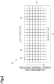
FIG. 2 is a schematic diagram illustrating a capturing region of an image capturing unit; -
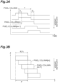
FIG. 3A is a schematic diagram illustrating exposure periods of pixels according to a general rolling shutter method; -
FIG. 3B is a schematic diagram illustrating exposure positions of pixels in a scanning direction according to a general rolling shutter method; -
FIG. 4A is a schematic diagram (comparative example) illustrating a state of acquisition of an image of a sample in a period for scanning in a first direction; -
FIG. 4B is a schematic diagram (comparative example) illustrating a state of acquisition of an image of a sample in a period for scanning in a second direction; -
FIG. 5 is a schematic diagram illustrating a state of overlapping of image data acquired in the comparative example illustrated inFIGS. 4A and 4B ; -
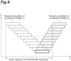
FIG. 6 is a schematic diagram illustrating a positional relationship between an exposure position in a scanning direction in the period for scanning in the first direction and an exposure position in a scanning direction in the period for scanning in the second direction in the comparative example illustrated inFIGS. 4A and 4B ; -
FIG. 7 is a diagram illustrating a relationship between scanning speed and shift amount of the imaged figure between image data in the comparative example; -
FIG. 8A is a schematic diagram (Examples) illustrating exposure periods of pixels according to the rolling shutter method in the period for scanning in the first direction; -
FIG. 8B is a schematic diagram (Examples) illustrating exposure periods of pixels according to the rolling shutter method in the period for scanning in the second direction; -
FIG. 9A is a schematic diagram (Example) illustrating a state of acquisition of an image of a sample in the period for scanning in the first direction; -
FIG. 9B is a schematic diagram (Examples) illustrating a state of acquisition of an image of a sample in the period for scanning in the second direction; -
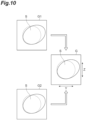
FIG. 10 is a schematic diagram illustrating a state of overlapping of image data acquired in Examples illustrated inFIGS. 9A and 9B ; -
FIG. 11 is a schematic diagram illustrating a positional relationship between an exposure position in a scanning direction in the period for scanning in the first direction and an exposure position in a scanning direction in the period for scanning in the second direction in Examples illustrated inFIGS. 9A and 9B ; -
FIG. 12 is a diagram illustrating a relationship between scanning speed and shift amount of the imaged figure between image data in Examples; -
FIG. 13 is a schematic diagram illustrating a setting example of a reference pixel column; -
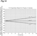
FIG. 14 is a diagram illustrating a relationship between scanning speed and shift amount of the imaged figure between image data in a case of setting the reference pixel column; -
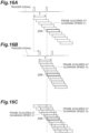
FIG. 15A is a schematic diagram illustrating an example of a method of setting the reference pixel column; -
FIG. 15B is a schematic diagram illustrating an example of a method of setting the reference pixel column; -
FIG. 15C is a schematic diagram illustrating an example of a method of setting the reference pixel column; -
FIG. 16A is a schematic diagram illustrating another example of a method of setting the reference pixel column; -
FIG. 16B is a schematic diagram illustrating another example of a method of setting the reference pixel column; -
FIG. 16C is a schematic diagram illustrating another example of a method of setting the reference pixel column; and -
FIG. 17 is a flowchart illustrating a sample observation method according to an embodiment of the present disclosure. - Hereinafter, preferred embodiments of a sample observation device and a sample observation method according to one aspect of the present disclosure will be described in detail with reference to the drawings.
-
FIG. 1 is a schematic configuration diagram illustrating a sample observation device according to an embodiment of the present disclosure. Asample observation device 1 illustrated inFIG. 1 is configured as a device that irradiates a sample S with planar light L1 and captures fluorescence or scattered light generated inside the sample S to acquire observation image data inside the sample S. - Examples of the
sample observation device 1 of this type include a slide scanner that acquires and displays an image of the sample S held on a slide glass, a plate reader that acquires image data of the sample S held on a microplate and analyzes the image data, and the like. Examples of the sample S to be observed include human or animal cells, tissues, organs, animals or plants themselves, and plant cells and tissues. In addition, the sample S may be contained in a solution, a gel, or a substance having a refractive index different from that of the sample S. - As illustrated in
FIG. 1 , thesample observation device 1 includes an irradiationoptical system 2, ascanning unit 3, an imagingoptical system 4, animage capturing unit 5, and acontrol unit 6. The irradiationoptical system 2 is an optical system that irradiates the sample S with the planar light L1. The irradiationoptical system 2 includes alight source 11 that outputs light L0 that is a generation source of the planar light L1, and alight shaping element 12 that shapes the light L0 into the planar light L1 and irradiates the sample S with the shaped planar light L1 along theoptical axis P 1. - Examples of the
light source 11 include laser light sources such as laser diodes and solid-state laser light sources. Thelight source 11 may be a light emitting diode, a superluminescent diode, or a lamp-based light source. The light L0 output from thelight source 11 is guided to thelight shaping element 12. - Examples of the
light shaping element 12 include a cylindrical lens, an axicon lens, a spatial light modulator, and the like. Thelight shaping element 12 may include an objective lens. Thelight shaping element 12 may include an objective scanner. In this case, thelight shaping element 12 may optically scan the linear light L0 output from thelight source 11 to form the planar light L1. In the sample S irradiated with the planar light L1 generated by thelight shaping element 12, observation light L2 is generated on an irradiation surface R of the planar light L1. The observation light L2 is, for example, fluorescence excited by the planar light L1, scattered light of the planar light L1, or diffusely reflected light of the planar light L1. - A
scanning unit 3 is a mechanism that scans the sample S with respect to the irradiation surface R of the planar light L1. Thescanning unit 3 includes acontainer 13 that holds the sample S and astage 14 that moves thecontainer 13. Thecontainer 13 is, for example, a microplate, a slide glass, a petri dish, or the like. Abottom surface 13a of thecontainer 13 is an input surface of the planar light L1. It is made of a transparent member having transparency to the planar light L1. Examples of the constituent material of thebottom surface 13a include glass, quartz, a rigid resin, and the like. - The
stage 14 holds thecontainer 13 and scans thecontainer 13 in a preset direction. Thestage 14 scans thecontainer 13 in one direction in a plane orthogonal to the optical axis P1 of the planar light L1. In the present embodiment, thestage 14 is capable of bidirectional scanning, and scans thecontainer 13 in a direction including a first direction and a second direction opposite to the first direction with respect to the irradiation surface R of the planar light L1. - In the following description, an orthogonal coordinate system including X, Y, and Z axes orthogonal to each other is used for convenience (see
FIG. 1 ). In the present embodiment, a direction along the optical axis P1 of the planar light L1 is defined as a Z axis, a scanning direction of the sample S (container 13) by thestage 14 is defined as a Y axis, and a direction orthogonal to the Y axis in a plane orthogonal to the optical axis P1 of the planar light L1 is defined as an X axis. - In a case where the
light shaping element 12 includes an optical scanner, the linear light L0 output from thelight source 11 in the Z direction is optically scanned in the X direction to form the planar light L1. According to the above definition, the irradiation surface R of the planar light L1 with respect to the sample S is a surface in the XZ plane. The depth direction of the sample S corresponds to the Z direction. Of the scanning direction of thecontainer 13 by thestage 14, the first direction is the +Y direction, and the second direction is the -Y direction. An operation of moving thecontainer 13 in the X direction may be performed between scanning in the first direction and scanning in the second direction. - The imaging
optical system 4 is an optical system that images the observation light L2 generated in the sample S by irradiation with the planar light L1. The imagingoptical system 4 includes, for example, anobjective lens 15, afilter switching unit 16, and animaging lens 17. Thefilter switching unit 16 is a filter wheel used for multi-wavelength measurement of the sample S, and holds afirst filter 18A and asecond filter 18B. Thefilter switching unit 16 is disposed on an imaging optical path between theobjective lens 15 and theimaging lens 17, and causes any one of thefirst filter 18A and thesecond filter 18B to be disposed on the imaging optical path. Thefirst filter 18A and thesecond filter 18B transmit a part of the observation light L2 (for example, fluorescence of a specific wavelength) according to optical characteristics thereof. - The optical axis of the imaging
optical system 4 is an observation axis P2 of the observation light L2. In the present embodiment, the observation axis P2 is inclined at a predetermined angle θ with respect to the irradiation surface R of the planar light L1. The angle θ also coincides with an angle formed by the optical axis P1 and the observation axis P2 of the planar light L1. The angle θ is, for example, 10° to 80°. From the viewpoint of improving the resolution of the observation image, the angle θ may be 20° to 70°. The angle θ may be 30° to 65° from the viewpoint of improving the resolution of the observation image and the stability of the visual field. - The observation axis P2 is not necessarily inclined with respect to the irradiation surface R of the planar light L1. That is, the observation axis P2 may be orthogonal to the irradiation surface R of the planar light L1 (the optical axis P1 of the planar light L1).
- The
image capturing unit 5 is a part that captures the observation light L2 generated in the sample S by irradiation with the planar light L1. Theimage capturing unit 5 include anarea image sensor 21 such as a CMOS image sensor and a CCD image sensor, for example. Thearea image sensor 21 is disposed on the imaging plane of the imagingoptical system 4. For example, as illustrated inFIG. 2 , thearea image sensor 21 includes apixel region 22 including a plurality ofpixels 23, and areadout unit 24 that externally reads out charge accumulated in eachpixel 23 out. Thearea image sensor 21 captures an optical image of the observation light L2 by a rolling shutter method in which the start of the exposure periods of thepixel columns 25 in the pixel region 22 (seeFIG. 2 ) is shifted by predetermined time, and generates image data based on the capturing result. - The
control unit 6 physically includes a memory such as a RAM and a ROM, a processor such as a CPU, a communication interface, a storage unit such as a hard disk, a display, and the like. Configuration examples of thecontrol unit 6 include a personal computer, a cloud server, and a smart device (smartphone, tablet terminal). Thecontrol unit 6 functions as anoperation control unit 7 that controls the operations of thelight source 11, thestage 14, thefilter switching unit 16, and theimage capturing unit 5 by executing a program stored in the memory by a processor such as a CPU. - The
control unit 6 as theoperation control unit 7 receives an input of operation of starting measurement by the user, and drives thelight source 11, thelight shaping element 12, thestage 14, thefilter switching unit 16, and theimage capturing unit 5. In addition, output conditions (wavelength or the like) of the light L0 by thelight source 11, scanning conditions (scanning speed or the like) of the sample S by thestage 14, and image capturing conditions (exposure period, resolution, etc.) by theimage capturing unit 5 are controlled according to settings input in advance. In a case where thelight shaping element 12 includes an optical scanner, theoperation control unit 7 controls the operation of the optical scanner of thelight shaping element 12. - A
control unit 6 may control the irradiationoptical system 2 so that the sample S is irradiated with the planar light L1 having different wavelengths between the period in which thescanning unit 3 scans the sample S in the first direction and the period in which thescanning unit 3 scans the sample S in the second direction. Thecontrol unit 6 may control thescanning unit 3 so that the sample S is scanned with respect to the irradiation surface R of the planar light L1 at different scanning speed V1 and V2 between the period in which thescanning unit 3 scans the sample S in the first direction and the period in which thescanning unit 3 scans the sample S in the second direction. Thecontrol unit 6 may control theimage capturing unit 5 so that roll times Tr (seeFIG. 3A ) represented by the time differences in the start of the exposure periods T in thepixel columns 25 are different from each other between the period in which thescanning unit 3 scans the sample S in the first direction and the period in which thescanning unit 3 scans the sample S in the second direction. - The
control unit 6 also functions as ananalysis unit 9 that analyzes the sample S. Thecontrol unit 6 as theanalysis unit 9 generates observation image data of the sample S on the basis of the image data generated by theimage capturing unit 5. The observation image data is, for example, a cross-sectional image of the sample S on a plane (XZ plane) orthogonal to the optical axis P1 of the planar light L1. By combining these cross-sectional images in the scanning direction (Y direction) of the sample S, three-dimensional information of the sample S can be obtained. Thecontrol unit 6 as theanalysis unit 9 analyzes the sample S on the basis of the generated observation image data to generate an analysis result. The analysis result is displayed on the display as necessary and stored in the storage unit. - Next, an image capturing method of the
image capturing unit 5 in thesample observation device 1 will be described in more detail. - As described above, the
image capturing unit 5 in thesample observation device 1 includes thearea image sensor 21 such as a CMOS image sensor or a CCD image sensor, and the rolling shutter method is adopted as the image capturing method. In general, in the rolling shutter method, as illustrated inFIG. 3A , the start of the exposure periods T of thepixel columns 25 in thepixel region 22 is shifted by predetermined time. That is, after a predetermined time has elapsed since the exposure of onepixel column 25 was instructed, the exposure of thenext pixel column 25 is started, and then the exposure period T is sequentially started until the desiredpixel column 25 is reached. - The time difference in the start of the exposure periods T in the
pixel columns 25 is referred to as roll time Tr and is a parameter that can be controlled by thecontrol unit 6. As illustrated inFIG. 3B , the resolution R(Y) in the Y direction in eachpixel column 25 can be calculated based on the product of the exposure period T and the scanning speed V of the sample S. The shift amount of the exposure position P of eachpixel column 25 is proportional to the scanning speed V of the sample S at the time of image capturing. - In image capturing by the general rolling shutter method, each frame includes an exposure period and a readout period. The time difference in the start of the readout period in each
pixel column 25 is referred to as line time Tl (seeFIG. 3A ). The line time Tl is a parameter that can be controlled by thecontrol unit 6, similarly to the roll time Tr. In the present embodiment, the roll time Tr and the line time Tl are set to equal values. Furthermore, in general, in a predetermined frame, after the exposure period T of apredetermined pixel column 25 has elapsed, the readout period of thepixel column 25 is started at the end of the exposure. Then, after the elapse of the readout period of thepredetermined pixel column 25 in the predetermined frame, the exposure of thepredetermined pixel column 25 in the next frame is started at the end of the readout. - In the present embodiment, various image capturing modes by the rolling shutter method can be applied. For example, the
image capturing unit 5 may perform an image capturing by the rolling shutter method in an image capturing mode in which starting the exposure is controlled on the basis of a trigger signal. Theimage capturing unit 5 may perform an image capturing by the rolling shutter method in an image capturing mode in which starting the exposure and the exposure period are controlled on the basis of a trigger signal. Theimage capturing unit 5 may perform an image capturing by the rolling shutter method in an image capturing mode in which starting the readout is controlled on the basis of a trigger signal. Theimage capturing unit 5 may perform an image capturing by the rolling shutter method in an image capturing mode in which starting the readout and the readout period are controlled on the basis of a trigger signal. -
FIGS. 4A and 4B illustrate a comparative example of the relationship between the shift amount of the exposure position P and the image of the sample S in the obtained image data. The example ofFIG. 4A is a schematic diagram illustrating a state of acquisition of an image of the sample S in a period for scanning in the first direction (+Y direction). As illustrated in the drawing, in image capturing the sample S in the period for scanning in the first direction (+Y direction), exposure is performed by eachpixel column 25 in the order of the nth frame, the (n + 1)th frame, and so on. - The exposure order of the
pixel columns 25 in each frame is arranged from a smaller column number to a larger column number. That is, the start of the exposure period T of thepixel column 25 in the mth column is temporally earlier than the start of the exposure period T of thepixel column 25 in the (m + 1) th column by the roll time Tr. In the image data acquired in this state, the exposure position P of the sample S corresponding to the exposure period T gradually shifts in the Y direction with respect to the position in the Z direction. Therefore, an imaged figure of the sample S is distorted in the Y direction with respect to the position in the Z direction (depth direction), with respect to the original existing position of the sample S. - In addition, the example of
FIG. 4B is a schematic diagram illustrating a state of acquisition of an image of the sample S in a period for scanning in the second direction (-Y direction). As illustrated in the drawing, in image capturing the sample S, exposure is performed by eachpixel column 25 in the order of the nth frame, the (n + 1) th frame, and so on. As illustrated in the drawing, in image capturing the sample S during the period for scanning in the second direction (-Y direction), exposure is performed by eachpixel column 25 in the order of the nth frame, the (n + 1)th frame, and so on, similarly to the case ofFIG. 4A . - The exposure order of the
pixel columns 25 in each frame is arranged from a smaller column number to a larger column number, as similar to the case ofFIG. 4A . That is, the start of the exposure period T of thepixel column 25 in the mth column is temporally earlier than the start of the exposure period T of thepixel column 25 in the (m + 1) th column by the roll time Tr. In the image data G2 acquired in this state, the exposure position P corresponding to the exposure period T gradually shifts in the Y direction (one direction opposite to the case inFIG. 4A ) with respect to the position in one direction of the Z direction (depth direction of the sample S). Therefore, the imaged figure of the sample S is distorted in the Y direction in opposite direction to the case inFIG. 4A (one direction opposite to the case inFIG. 4A ) with respect to the position in the Z direction (depth direction of the sample S), with respect to the original existing position of the sample S. - In the image data G in which the image data G1 of the sample S acquired in the example of
FIG. 4A and the image data G2 of the sample S acquired in the example ofFIG. 4B are superimposed on each other, as illustrated inFIG. 5 , the images overlap each other in the vicinity of the bottom surface of the sample S in the depth direction, but the shift amount of the imaged figure of the sample S increases in the vicinity of the end portion of the sample S in the depth direction due to the opposite direction of the distortion in the Y direction. -
FIGS. 4A and 4B illustrate the case where the scanning speed V1 in the first direction is equal to the scanning speed V2 in the second direction. However, as illustrated inFIG. 6 , the shift amount of the imaged figure of the sample S in the image data G becomes more remarkable and asymmetric as the difference between the scanning speed V1 and the scanning speed V2 increases. In addition, in thesample observation device 1, since thefilter switching unit 16 can switch between thefirst filter 18A and thesecond filter 18B, it is also assumed that multi-wavelength measurement using a plurality of excitation wavelengths and fluorescence wavelengths is performed at the time of bidirectional scanning. - In the multi-wavelength measurement, the observation light L2 having different wavelengths is imaged between the period of scanning in the first direction and the period of scanning in the second direction. For this reason, as illustrated in
FIG. 5 , when the image of the sample S is distorted in the opposite direction in the image data G, a color shift may occur in the imaged figure of the sample S among a portion where the images overlap, a portion where the images do not overlap and are shifted in one direction, and a portion where the images do not overlap and are shifted in the opposite direction. -
FIG. 7 is a diagram illustrating a relationship between the scanning speed and the shift amount of the imaged figure between image data in the comparative example. InFIG. 7 , the roll time Tr is set to 10 [µs/line], the resolution R(Y) is set to 2.75 [µm], the scanning speed V1 with respect to the first direction is set to 1 [mm/s], and what is plotted is the shift amount of the imaged figure between the image data [% (= shift amount of exposure position/R(Y))] when the scanning speed V2 with respect to the second direction is changed. From the results in the drawing, it can be seen that, in the comparative example, the shift amount of the imaged figure between the image data is theoretically 0 in thefirst pixel column 25 in which there is no shift at the timing of starting the exposure period T, but the shift amount of the imaged figure between the image data increases in proportion to the difference between the scanning speed V1 and the scanning speed V2 in theother pixel columns 25. Furthermore, in the comparative example, it can be seen that, in a case where the difference between the scanning speed V1 and the scanning speed V2 is the same, as the column number of thepixel column 25 increases (the exposure order goes later), the shift amount of the imaged figure between the image data increases. - In contrast to such comparative example, in the present embodiment, the
control unit 6 controls theimage capturing unit 5 so that the exposure order of thepixel columns 25 is reversed between the period in which thescanning unit 3 scans the sample S in the first direction and the period in which thescanning unit 3 scans the sample S in the second direction. More specifically, in the period in which thescanning unit 3 scans the sample S in the first direction, as illustrated inFIG. 8A , the exposure order of thepixel columns 25 in each frame is arranged from the smaller column number to the larger column number. That is, the start of the exposure period T of thepixel column 25 in the mth column is temporally earlier than the start of the exposure period T of thepixel column 25 in the (m + 1) th column by the roll time Tr. - On the other hand, in the period in which the
scanning unit 3 scans the sample S in the second direction, as illustrated inFIG. 8B , the exposure order of thepixel columns 25 in each frame is reversed and arranged from the larger column number to the smaller column number. That is, the start of the exposure period T of thepixel column 25 in the (m + 1)th column is temporally earlier than the start of the exposure period T of thepixel column 25 in the mth column by the roll time Tr. - In the image data G1 acquired in the state of
FIG. 8A , as illustrated inFIG. 9A , the exposure position P corresponding to the exposure period T gradually shifts in the Y direction with respect to the position in one direction of the Z direction (depth direction of the sample S). Therefore, similarly to the case ofFIG. 4A , the imaged figure of the sample S is distorted in the Y direction with respect to the position in the Z direction (depth direction), with respect to the original existing position of the sample S. On the other hand, in the image data G2 acquired in the state ofFIG. 8B , as illustrated inFIG. 9B , the exposure position P corresponding to the exposure period T gradually shifts in the Y direction (the one direction same as the case ofFIG. 9A ) with respect to the position in one direction of the Z direction (depth direction of the sample S). Therefore, the imaged figure of the sample S is distorted in the Y direction, which is the same direction as the case ofFIG. 9A , with respect to the position in the Z direction (depth direction of the sample S), with respect to the original existing position of the sample S. - In the image data G in which the image data G1 of the sample S acquired in the example of
FIG. 9A overlaps the image data G2 of the sample S acquired in the example ofFIG. 9B , as illustrated inFIG. 10 , although the imaged figure of the sample S is distorted with respect to the original existing position of the sample S, the distortion direction in the Y direction is aligned, thereby reducing the shift of the imaged figure of the sample S between the image data G1 and G2. The effect of reducing the shift of the imaged figure of the sample S in the present embodiment is remarkably exhibited even when there is a difference between the scanning speed V1 and the scanning speed V2 as illustrated inFIG. 11 . In the multi-wavelength measurement, as illustrated inFIG. 10 , the direction of the distortion of the imaged figure of the sample S is aligned in the overlapping image data G, thereby suppressing the occurrence of the color shift in the image of the sample S. -
FIG. 12 is a diagram illustrating a relationship between the scanning speed and the shift amount of the imaged figure between image data in Examples. InFIG. 12 , similarly toFIG. 7 , the roll time Tr is set to 10 [µs/line], the resolution R(Y) is set to 2.75 [µm], the scanning speed V1 with respect to the first direction is set to 1 [mm/s], and what is plotted is the shift amount of the imaged figure between the image data [% (= shift amount of exposure position/R(Y))] when the scanning speed V2 with respect to the second direction is changed. From the results in the drawing, Example is the same as the comparative example in that the shift amount of the imaged figure between the image data increases in proportion to the difference between the scanning speed V1 and the scanning speed V2, but it can be seen that the shift amount of the imaged figure between the image data is reduced as compared with the case ofFIG. 7 . - There is a tendency that if the absolute value of the shift amount of the imaged figure between the image data G1 and G2 with respect to the resolution R exceeds 50%, it is difficult to maintain the analysis accuracy of the shape and the existing position of the sample. In addition, in a case where the absolute value of the shift amount of the imaged figure between the image data G1 and G2 with respect to the resolution R exceeds 20%, a problem of color shift of the image in multi-wavelength measurement remarkably appears. Therefore, in the
sample observation device 1, thecontrol unit 6 controls at least one of thescanning unit 3 and theimage capturing unit 5 such that an absolute value of the shift amount of the exposure position P in eachpixel column 25 is 50% or less of the resolution between the period in which thescanning unit 3 scans the sample S in the first direction and the period in which thescanning unit 3 scans the sample S in the second direction. Particularly, when performing the multi-wavelength measurement, thecontrol unit 6 controls at least one of thescanning unit 3 and theimage capturing unit 5 such that an absolute value of the shift amount of the exposure position P in eachpixel column 25 is 20% or less of the resolution between the period in which thescanning unit 3 scans the sample S in the first direction and the period in which thescanning unit 3 scans the sample S in the second direction. Examples of the control parameters in this case include scanning speed V1 and V2, roll time Tr, and an exposure period T. - In a case where the scanning speed V1 and V2 are different from each other, from the viewpoint of further reducing the difference in distortion of the imaged figure of the sample S between the image data G1 and G2, the
control unit 6 may set thereference pixel column 25R so that the exposure positions P of the intermediate pixel columns in thepixel columns 25 coincide with each other when the exposure positions P in thepixel columns 25 are overlapped on the scanning axis between the period in which thescanning unit 3 scans the sample S in the first direction and the period in which thescanning unit 3 scans the sample S in the second direction as illustrated inFIG. 13 . - The
reference pixel column 25R is arbitrarily selected from the intermediate pixel columns excluding the array ends. In the example ofFIG. 13 , in the first toeleventh pixel columns 25, thefifth pixel column 25 is thereference pixel column 25R. By overlapping the exposure positions P in thepixel columns 25 on the scanning axis using such areference pixel column 25R, even in a case where the scanning speed V1 and V2 are different from each other, the shift amount of the imaged figure of the sample S between the image data G1 and G2 can be sufficiently reduced. -
FIG. 14 is a diagram illustrating a relationship between the scanning speed and the shift amount of the imaged figure between image data in a case of setting thereference pixel column 25R. InFIG. 14 , similarly toFIGS. 7 and12 , the roll time Tr is set to 10 [µs/line], the resolution R(Y) is set to 2.75 [µm], the scanning speed V1 with respect to the first direction is set to 1 [mm/s], and what is plotted is the shift amount of the imaged figure between the image data [% (= shift amount of exposure position/R(Y))] when the scanning speed V2 with respect to the second direction is changed. From the results in the drawing, it can be seen that the shift amount of the imaged figure between the image data is theoretically 0 in thefifth pixel column 25 that is thereference pixel column 25R, and the absolute value of the shift amount of the image between the image data with respect to the resolution R is suppressed to less than 20% also in thefirst pixel column 25 that is the array end and thetenth pixel column 25 close to the array end. - The method of setting the
reference pixel column 25R is not particularly limited, but for example, a method using a linear encoder that detects the position of thestage 14 is conceivable. In the example ofFIGS. 15A to 15C , the linear encoder outputs the trigger signal every time thestage 14 moves by a predetermined distance in the Y direction. In theimage capturing unit 5, the interval between the input trigger signals is set as the exposure period T, the exposure of the nth frame is started at the timing of the input of the first trigger signal, the exposure of the nth frame is ended at the timing of the input of the next trigger signal, and at the same time, the exposure of the (n + 1)th frame is started. - When the timings of inputting the trigger signals are aligned between the period of scanning in the first direction and the period of scanning in the second direction, the
first pixel column 25 is set as thereference pixel column 25R as illustrated inFIGS. 15A to 15C . Furthermore, as illustrated inFIGS. 16A to 16C , an arbitrary intermediate pixel column can be set as thereference pixel column 25R by adjusting the trigger signal in the scanning period in the second direction so that the exposure period T of the intermediate pixel column excluding the array end coincides with the input of the trigger signal in the scanning period in the first direction. -
FIG. 17 is a flowchart illustrating a sample observation method according to an embodiment of the present disclosure. As illustrated in the drawing, the sample observation method includes an irradiating step S01, a scanning step S02, an image capturing step S03, and an analysis step S04. - The irradiating step S01 is a step that irradiates the sample S with the planar light L1. In the irradiating step S01, the light L0 output from the
light source 11 is shaped into planar light L1, and the sample S held in thecontainer 13 is irradiated with the planar light L1. The observation light L2 based on the irradiation of the planar light L1 is generated from the sample S. The scanning step S02 is a step that scans the sample S with respect to the irradiation surface R of the planar light L1. Here, thestage 14 scans the sample S in a direction including the first direction (+Y direction) and the second direction (-Y direction) opposite to the first direction. - The image capturing step S03 is a step of image capturing the observation light L2 generated in the sample S by the irradiation of the planar light L1 and outputting the image data G based on the capturing result. In the image capturing step S03, using the
area image sensor 21 that performs image capturing by the rolling shutter method in which the start of the exposure period T of eachpixel column 25 in thepixel region 22 is shifted by predetermined time, the exposure order in thepixel columns 25 is reversed between the period in which the sample S is scanned in the first direction and the period in which the sample S is scanned in the second direction. - The analysis step S04 is a step of analyzing the sample S. In the analysis step S04, observation image data of the sample S is generated on the basis of the image data G obtained in the image capturing step S03, the sample S is analyzed on the basis of the generated observation image data, and an analysis result is generated.
- As described above, in the
sample observation device 1, the exposure order in eachpixel column 25 is reversed between a period in which thescanning unit 3 scans the sample S in the first direction and a period in which thescanning unit 3 scans the sample S in the second direction. As a result, the direction of distortion of the imaged figure of the sample S can be aligned between the image data G1 acquired in the period for scanning in the first direction and the image data G2 acquired in the period for scanning in the second direction. As a result, even when the capturing image by the rolling shutter method is adopted, it is possible to reduce the difference in distortion of the imaged figure of the sample S between the image data G. By reducing the difference in distortion of the imaged figure of the sample S, the analysis accuracy of the shape and the existing position of the sample S can be improved even when processing is performed between the pieces of image data G. - According to the present embodiment, the
control unit 6 can control the irradiationoptical system 2 so that the sample S is irradiated with the planar light L1 having different wavelengths between the period in which thescanning unit 3 scans the sample S in the first direction and the period in which thescanning unit 3 scans the sample S in the second direction. Therefore, multi-wavelength measurement with planar light L1 of a plurality of wavelengths becomes possible. By aligning the direction of distortion of the imaged figure of the sample S by the above-described method, the occurrence of color shift of the image of the sample S in the image data G can be reduced even when the sample S is bidirectionally scanned using the planar light L1 of a plurality of wavelengths. - According to the present embodiment, the
control unit 6 can control thescanning unit 3 so that the sample S is scanned with respect to the irradiation surface R of the planar light L1 at different scanning speed V1 and V2 between the period in which thescanning unit 3 scans the sample S in the first direction and the period in which thescanning unit 3 scans the sample S in the second direction. Therefore, measurement with different scanning conditions is possible. By aligning the direction of distortion of the image of the sample S by the above-described method, it is possible to reduce the difference in distortion of the imaged figure of the sample S between the image data G1 and G2 even when the sample S is scanned using a plurality of scanning conditions. - According to the present embodiment, the
control unit 6 can control theimage capturing unit 5 so that the roll time Tr represented by the time differences in the start of the exposure periods T in thepixel columns 25 are different from each other between the period in which thescanning unit 3 scans the sample S in the first direction and the period in which thescanning unit 3 scans the sample S in the second direction. Therefore, measurement with different exposure conditions is possible. By changing the inclination amount of distortion of the image of the sample S by the above-described method, it is possible to adjust the difference in distortion of the imaged figure of the sample S between the image data G1 and G2 even when the sample S is scanned using a plurality of exposure conditions. - According to the present embodiment, the
control unit 6 can control at least one of thescanning unit 3 and theimage capturing unit 5 such that an absolute value of the shift amount of the exposure position P in eachpixel column 25 is 50% or less, or 20% or less of the resolution R(Y) between the period in which thescanning unit 3 scans the sample S in the first direction and the period in which thescanning unit 3 scans the sample S in the second direction. By suppressing the absolute value of the shift amount of the exposure position P to 50% or less of the resolution R(Y), it is possible to avoid the deviation of the analysis position in the sample S. Further, by suppressing the absolute value of the shift amount of the exposure position P to 20% or less of the resolution R(Y), it is possible to further reliably avoid the deviation of the analysis position in the sample S. In addition, even in the case of performing multi-wavelength measurement, it is possible to reduce the occurrence of color shift of the image of the sample S. - According to the present embodiment, the
control unit 6 can set thereference pixel column 25R so that the exposure positions P of the intermediate pixel columns in thepixel columns 25 coincide with each other when the exposure positions P in thepixel columns 25 are overlapped on the scanning axis between the period in which thescanning unit 3 scans the sample S in the first direction and the period in which thescanning unit 3 scans the sample S in the second direction. By setting thereference pixel column 25R, it is easy to overlap images of the same region of the sample S. In addition, even when the scanning speed V1 and V2 are different between the period for scanning in the first direction and the period for scanning in the second direction, it is possible to effectively reduce the difference in distortion of the imaged figure of the sample S between the image data G1 and G2.
Claims (14)
- A sample observation device comprising:an irradiation optical system configured to irradiate a sample with planar light;a scanning unit configured to scan the sample in a direction including a first direction and a second direction opposite to the first direction with respect to an irradiation surface of the planar light;an image capturing unit configured to include a pixel region for image capturing observation light generated in the sample by irradiation of the planar light to output image data based on a capturing result of the observation light in the pixel region; anda control unit configured to control respective operations of the irradiation optical system, the scanning unit, and the image capturing unit, whereinthe image capturing unit includes an area image sensor that performs image capturing by a rolling shutter method in which a start of an exposure period of each of pixel columns in the pixel region is shifted by predetermined time, andthe control unit controls the image capturing unit so that an exposure order in each of the pixel columns is reversed between a period in which the scanning unit scans the sample in the first direction and a period in which the scanning unit scans the sample in the second direction.
- The sample observation device according to claim 1 wherein the control unit is configured to control the irradiation optical system so that the sample is irradiated with planar light having different wavelengths between a period in which the scanning unit scans the sample in the first direction and a period in which the scanning unit scans the sample in the second direction.
- The sample observation device according to claim 1 or 2, wherein the control unit is configured to control the scanning unit so that the sample is scanned with respect to the irradiation surface of the planar light at different scanning speed between a period in which the scanning unit scans the sample in the first direction and a period in which the scanning unit scans the sample in the second direction.
- The sample observation device according to any one of claims 1 to 3, wherein the control unit is configured to control the image capturing unit so that roll time represented by a time difference of a start of an exposure period of each of the pixel columns is different from each other between a period in which the scanning unit scans the sample in the first direction and a period in which the scanning unit scans the sample in the second direction.
- The sample observation device according to any one of claims 1 to 4, wherein the control unit is configured to control at least one of the scanning unit and the image capturing unit such that an absolute value of shift amount of an exposure position in each of the pixel columns is 50% or less of resolution between a period in which the scanning unit scans the sample in the first direction and a period in which the scanning unit scans the sample in the second direction.
- The sample observation device according to any one of claims 1 to 5, wherein the control unit is configured to control at least one of the scanning unit and the image capturing unit such that an absolute value of shift amount of an exposure position in each of the pixel columns is 20% or less of resolution between a period in which the scanning unit scans the sample in the first direction and a period in which the scanning unit scans the sample in the second direction.
- The sample observation device according to any one of claims 1 to 6, wherein the control unit is configured to set a reference pixel column so that exposure positions of intermediate pixel columns in the pixel columns coincide with each other when exposure positions in the pixel columns are overlapped on a scanning axis between a period in which the scanning unit scans the sample in the first direction and a period in which the scanning unit scans the sample in the second direction.
- A sample observation method comprising the steps of:irradiating a sample with planar light;scanning the sample in a direction including a first direction and a second direction opposite to the first direction with respect to an irradiation surface of the planar light; andimage capturing by using a pixel region for image capturing observation light generated in the sample by irradiation of the planar light to output image data based on a capturing result of the observation light in the pixel region, whereinthe image capturing step uses an area image sensor that performs image capturing by a rolling shutter method in which a start of an exposure period of each of pixel columns in the pixel region is shifted by predetermined time, and the scanning step reverses an exposure order in each of the pixel columns between a period in which the sample is scanned in the first direction and a period in which the sample is scanned in the second direction.
- The sample observation method according to claim 8, wherein in the irradiating step, the sample is irradiated with planar light having different wavelengths between a period in which the sample is scanned in the first direction and a period in which the sample is scanned in the second direction.
- The sample observation method according to claim 8 or 9, wherein in the scanning step, the sample is scanned with respect to an irradiation surface of the planar light at different scanning speed between a period in which the sample is scanned in the first direction and a period in which the sample is scanned in the second direction.
- The sample observation method according to any one of claims 8 to 10, wherein in the image capturing step, roll time represented by a time difference of a start of an exposure period in each of the pixel columns is different from each other between a period in which the sample is scanned in the first direction and a period in which the sample is scanned in the second direction.
- The sample observation method according to any one of claims 8 to 11, wherein an absolute value of shift amount of an exposure position in each of the pixel columns is 50% or less of resolution between a period in which the sample is scanned in the first direction and a period in which the sample is scanned in the second direction.
- The sample observation method according to any one of claims 8 to 12, wherein an absolute value of shift amount of an exposure position in each of the pixel columns is 20% or less of resolution between a period in which the sample is scanned in the first direction and a period in which the sample is scanned in the second direction.
- The sample observation method according to any one of claims 8 to 13, wherein in the image capturing step, a reference pixel column is set so that exposure positions of intermediate pixel columns in the pixel columns coincide with each other when the exposure positions in the pixel columns are overlapped on a scanning axis between a period in which the sample is scanned in the first direction and a period in which the sample is scanned in the second direction.
Applications Claiming Priority (1)
| Application Number | Priority Date | Filing Date | Title |
|---|---|---|---|
| JP2022209706A JP7847081B2 (en) | 2022-12-27 | 2022-12-27 | Sample observation apparatus and sample observation method |
Publications (3)
| Publication Number | Publication Date |
|---|---|
| EP4394477A1 true EP4394477A1 (en) | 2024-07-03 |
| EP4394477B1 EP4394477B1 (en) | 2025-12-31 |
| EP4394477C0 EP4394477C0 (en) | 2025-12-31 |
Family
ID=88745982
Family Applications (1)
| Application Number | Title | Priority Date | Filing Date |
|---|---|---|---|
| EP23208497.0A Active EP4394477B1 (en) | 2022-12-27 | 2023-11-08 | SAMPLE OBSERVATION DEVICE AND SAMPLE OBSERVATION PROCEDURES |
Country Status (4)
| Country | Link |
|---|---|
| US (1) | US12663375B2 (en) |
| EP (1) | EP4394477B1 (en) |
| JP (1) | JP7847081B2 (en) |
| ES (1) | ES3062337T3 (en) |
Citations (2)
| Publication number | Priority date | Publication date | Assignee | Title |
|---|---|---|---|---|
| WO2011120629A1 (en) * | 2010-03-29 | 2011-10-06 | Lavision Biotec Gmbh | Method and arrangement for microscopy |
| JP2018063292A (en) | 2016-10-11 | 2018-04-19 | 浜松ホトニクス株式会社 | Sample observation apparatus and sample observation method |
Family Cites Families (7)
| Publication number | Priority date | Publication date | Assignee | Title |
|---|---|---|---|---|
| EP2990849B1 (en) * | 2013-04-26 | 2020-09-02 | Hamamatsu Photonics K.K. | Image acquisition device and method and system for creating focus map for specimen |
| JP6134249B2 (en) * | 2013-11-01 | 2017-05-24 | 浜松ホトニクス株式会社 | Image acquisition device and image acquisition method of image acquisition device |
| JP6993206B2 (en) * | 2017-12-20 | 2022-01-13 | オリンパス株式会社 | Scanning laser microscope |
| JP7298993B2 (en) * | 2018-04-09 | 2023-06-27 | 浜松ホトニクス株式会社 | Specimen observation device and specimen observation method |
| EP3786685B1 (en) * | 2019-09-02 | 2026-08-12 | Leica Microsystems CMS GmbH | Control device and method for controlling a microscope, microscope and computer program product |
| WO2021097300A1 (en) | 2019-11-13 | 2021-05-20 | University Of Washington | Open-top light-sheet microscopy with a non-orthogonal arrangement of illumination and collection objectives |
| DE102020104634B4 (en) * | 2020-02-21 | 2023-12-28 | Excelitas Pco Gmbh | Method for reading out image data and for detecting an object, image recording device and light sheet microscope |
-
2022
- 2022-12-27 JP JP2022209706A patent/JP7847081B2/en active Active
-
2023
- 2023-10-20 US US18/382,177 patent/US12663375B2/en active Active
- 2023-11-08 EP EP23208497.0A patent/EP4394477B1/en active Active
- 2023-11-08 ES ES23208497T patent/ES3062337T3/en active Active
Patent Citations (3)
| Publication number | Priority date | Publication date | Assignee | Title |
|---|---|---|---|---|
| WO2011120629A1 (en) * | 2010-03-29 | 2011-10-06 | Lavision Biotec Gmbh | Method and arrangement for microscopy |
| JP2018063292A (en) | 2016-10-11 | 2018-04-19 | 浜松ホトニクス株式会社 | Sample observation apparatus and sample observation method |
| EP3528030A1 (en) * | 2016-10-11 | 2019-08-21 | Hamamatsu Photonics K.K. | Sample observation device and sample observation method |
Non-Patent Citations (3)
| Title |
|---|
| EUGEN BAUMGART: "Scanned light sheet microscopy with confocal slit detection", OPTICS EXPRESS, vol. 20, no. 19, 10 September 2012 (2012-09-10), US, pages 21805, XP093152035, ISSN: 1094-4087, DOI: 10.1364/OE.20.021805 * |
| MIGLIORI BIANCA ET AL: "Light sheet theta microscopy for rapid high-resolution imaging of large biological samples", BMC BIOLOGY, vol. 16, no. 1, 1 December 2018 (2018-12-01), GB, XP093132399, ISSN: 1741-7007, DOI: 10.1186/s12915-018-0521-8 * |
| VENKATAKAUSHIK VOLETI ET AL: "Supplementary Notes - SCAPE 2.0 Optical resolution characterization", NATURE METHODS, 27 September 2019 (2019-09-27), XP055720382, DOI: 10.1038/s41592-019-0579-4 * |
Also Published As
| Publication number | Publication date |
|---|---|
| US12663375B2 (en) | 2026-06-23 |
| JP2024093373A (en) | 2024-07-09 |
| EP4394477B1 (en) | 2025-12-31 |
| EP4394477C0 (en) | 2025-12-31 |
| ES3062337T3 (en) | 2026-04-10 |
| JP7847081B2 (en) | 2026-04-16 |
| US20240210319A1 (en) | 2024-06-27 |
Similar Documents
| Publication | Publication Date | Title |
|---|---|---|
| CA2947520C (en) | Improvements in imaging microscope samples | |
| CN108111775B (en) | Image acquisition device and imaging device | |
| US20220283420A1 (en) | Sample observation device and sample observation method | |
| JP5793219B1 (en) | Imaging apparatus and imaging method | |
| US20200033564A1 (en) | Image capturing apparatus and focusing method thereof | |
| US20200192059A1 (en) | Imaging control apparatus, method, and program | |
| EP4394477B1 (en) | SAMPLE OBSERVATION DEVICE AND SAMPLE OBSERVATION PROCEDURES | |
| US12634597B2 (en) | Sample observation device and sample observation method | |
| US11391935B2 (en) | Sample observation device and sample observation method | |
| US9860437B2 (en) | Image capturing apparatus and focusing method thereof | |
| US20240184090A1 (en) | Sample observation device and sample observation method | |
| EP4137864B1 (en) | Sample observation device and sample observation method | |
| US11635582B2 (en) | Microscope apparatus and program | |
| JP6754408B2 (en) | Sample observation device and sample observation method | |
| JP2026010292A (en) | Observation device and observation method | |
| JP2020194190A (en) | Sample observation device and sample observation method |
Legal Events
| Date | Code | Title | Description |
|---|---|---|---|
| PUAI | Public reference made under article 153(3) epc to a published international application that has entered the european phase |
Free format text: ORIGINAL CODE: 0009012 |
|
| STAA | Information on the status of an ep patent application or granted ep patent |
Free format text: STATUS: THE APPLICATION HAS BEEN PUBLISHED |
|
| AK | Designated contracting states |
Kind code of ref document: A1 Designated state(s): AL AT BE BG CH CY CZ DE DK EE ES FI FR GB GR HR HU IE IS IT LI LT LU LV MC ME MK MT NL NO PL PT RO RS SE SI SK SM TR |
|
| STAA | Information on the status of an ep patent application or granted ep patent |
Free format text: STATUS: REQUEST FOR EXAMINATION WAS MADE |
|
| 17P | Request for examination filed |
Effective date: 20240710 |
|
| RBV | Designated contracting states (corrected) |
Designated state(s): AL AT BE BG CH CY CZ DE DK EE ES FI FR GB GR HR HU IE IS IT LI LT LU LV MC ME MK MT NL NO PL PT RO RS SE SI SK SM TR |
|
| STAA | Information on the status of an ep patent application or granted ep patent |
Free format text: STATUS: EXAMINATION IS IN PROGRESS |
|
| 17Q | First examination report despatched |
Effective date: 20241121 |
|
| GRAP | Despatch of communication of intention to grant a patent |
Free format text: ORIGINAL CODE: EPIDOSNIGR1 |
|
| STAA | Information on the status of an ep patent application or granted ep patent |
Free format text: STATUS: GRANT OF PATENT IS INTENDED |
|
| RIC1 | Information provided on ipc code assigned before grant |
Ipc: G02B 21/00 20060101AFI20250805BHEP Ipc: G02B 21/36 20060101ALI20250805BHEP Ipc: H04N 23/74 20230101ALI20250805BHEP Ipc: H04N 25/531 20230101ALI20250805BHEP Ipc: H04N 23/56 20230101ALI20250805BHEP |
|
| INTG | Intention to grant announced |
Effective date: 20250902 |
|
| RAP3 | Party data changed (applicant data changed or rights of an application transferred) |
Owner name: HAMAMATSU PHOTONICS K.K. |
|
| GRAS | Grant fee paid |
Free format text: ORIGINAL CODE: EPIDOSNIGR3 |
|
| GRAA | (expected) grant |
Free format text: ORIGINAL CODE: 0009210 |
|
| STAA | Information on the status of an ep patent application or granted ep patent |
Free format text: STATUS: THE PATENT HAS BEEN GRANTED |
|
| AK | Designated contracting states |
Kind code of ref document: B1 Designated state(s): AL AT BE BG CH CY CZ DE DK EE ES FI FR GB GR HR HU IE IS IT LI LT LU LV MC ME MK MT NL NO PL PT RO RS SE SI SK SM TR |
|
| REG | Reference to a national code |
Ref country code: CH Ref legal event code: F10 Free format text: ST27 STATUS EVENT CODE: U-0-0-F10-F00 (AS PROVIDED BY THE NATIONAL OFFICE) Effective date: 20251231 Ref country code: GB Ref legal event code: FG4D |
|
| REG | Reference to a national code |
Ref country code: CH Ref legal event code: R17 Free format text: ST27 STATUS EVENT CODE: U-0-0-R10-R17 (AS PROVIDED BY THE NATIONAL OFFICE) Effective date: 20260107 |
|
| REG | Reference to a national code |
Ref country code: DE Ref legal event code: R096 Ref document number: 602023010389 Country of ref document: DE |
|
| REG | Reference to a national code |
Ref country code: IE Ref legal event code: FG4D |
|
| U01 | Request for unitary effect filed |
Effective date: 20260128 |
|
| U07 | Unitary effect registered |
Designated state(s): AT BE BG DE DK EE FI FR IT LT LU LV MT NL PT RO SE SI Effective date: 20260203 |
|
| REG | Reference to a national code |
Ref country code: ES Ref legal event code: FG2A Ref document number: 3062337 Country of ref document: ES Kind code of ref document: T3 Effective date: 20260410 |
|
| PG25 | Lapsed in a contracting state [announced via postgrant information from national office to epo] |
Ref country code: NO Free format text: LAPSE BECAUSE OF FAILURE TO SUBMIT A TRANSLATION OF THE DESCRIPTION OR TO PAY THE FEE WITHIN THE PRESCRIBED TIME-LIMIT Effective date: 20260331 |
|
| PG25 | Lapsed in a contracting state [announced via postgrant information from national office to epo] |
Ref country code: HR Free format text: LAPSE BECAUSE OF FAILURE TO SUBMIT A TRANSLATION OF THE DESCRIPTION OR TO PAY THE FEE WITHIN THE PRESCRIBED TIME-LIMIT Effective date: 20251231 |
|
| PG25 | Lapsed in a contracting state [announced via postgrant information from national office to epo] |
Ref country code: RS Free format text: LAPSE BECAUSE OF FAILURE TO SUBMIT A TRANSLATION OF THE DESCRIPTION OR TO PAY THE FEE WITHIN THE PRESCRIBED TIME-LIMIT Effective date: 20260331 |
|
| U1N | Appointed representative for the unitary patent procedure changed after the registration of the unitary effect |
Representative=s name: MARKS & CLERK LLP; GB |
|
| PG25 | Lapsed in a contracting state [announced via postgrant information from national office to epo] |
Ref country code: SM Free format text: LAPSE BECAUSE OF FAILURE TO SUBMIT A TRANSLATION OF THE DESCRIPTION OR TO PAY THE FEE WITHIN THE PRESCRIBED TIME-LIMIT Effective date: 20251231 |
|
| PG25 | Lapsed in a contracting state [announced via postgrant information from national office to epo] |
Ref country code: PL Free format text: LAPSE BECAUSE OF FAILURE TO SUBMIT A TRANSLATION OF THE DESCRIPTION OR TO PAY THE FEE WITHIN THE PRESCRIBED TIME-LIMIT Effective date: 20251231 |
|
| PG25 | Lapsed in a contracting state [announced via postgrant information from national office to epo] |
Ref country code: IS Free format text: LAPSE BECAUSE OF FAILURE TO SUBMIT A TRANSLATION OF THE DESCRIPTION OR TO PAY THE FEE WITHIN THE PRESCRIBED TIME-LIMIT Effective date: 20260430 |
|
| PG25 | Lapsed in a contracting state [announced via postgrant information from national office to epo] |
Ref country code: CZ Free format text: LAPSE BECAUSE OF FAILURE TO SUBMIT A TRANSLATION OF THE DESCRIPTION OR TO PAY THE FEE WITHIN THE PRESCRIBED TIME-LIMIT Effective date: 20251231 |
|
| PG25 | Lapsed in a contracting state [announced via postgrant information from national office to epo] |
Ref country code: SK Free format text: LAPSE BECAUSE OF FAILURE TO SUBMIT A TRANSLATION OF THE DESCRIPTION OR TO PAY THE FEE WITHIN THE PRESCRIBED TIME-LIMIT Effective date: 20251231 |