EP4394466A1 - Multi-cavity optical connector with cable management - Google Patents
Multi-cavity optical connector with cable management Download PDFInfo
- Publication number
- EP4394466A1 EP4394466A1 EP23212881.9A EP23212881A EP4394466A1 EP 4394466 A1 EP4394466 A1 EP 4394466A1 EP 23212881 A EP23212881 A EP 23212881A EP 4394466 A1 EP4394466 A1 EP 4394466A1
- Authority
- EP
- European Patent Office
- Prior art keywords
- backshell
- nest
- housing
- connector
- eyelet
- Prior art date
- Legal status (The legal status is an assumption and is not a legal conclusion. Google has not performed a legal analysis and makes no representation as to the accuracy of the status listed.)
- Pending
Links
Images


Classifications
-
- G—PHYSICS
- G02—OPTICS
- G02B—OPTICAL ELEMENTS, SYSTEMS OR APPARATUS
- G02B6/00—Light guides; Structural details of arrangements comprising light guides and other optical elements, e.g. couplings
- G02B6/24—Coupling light guides
- G02B6/36—Mechanical coupling means
- G02B6/38—Mechanical coupling means having fibre to fibre mating means
- G02B6/3807—Dismountable connectors, i.e. comprising plugs
- G02B6/3869—Mounting ferrules to connector body, i.e. plugs
- G02B6/387—Connector plugs comprising two complementary members, e.g. shells, caps, covers, locked together
-
- G—PHYSICS
- G02—OPTICS
- G02B—OPTICAL ELEMENTS, SYSTEMS OR APPARATUS
- G02B6/00—Light guides; Structural details of arrangements comprising light guides and other optical elements, e.g. couplings
- G02B6/24—Coupling light guides
- G02B6/36—Mechanical coupling means
- G02B6/38—Mechanical coupling means having fibre to fibre mating means
- G02B6/3807—Dismountable connectors, i.e. comprising plugs
- G02B6/381—Dismountable connectors, i.e. comprising plugs of the ferrule type, e.g. fibre ends embedded in ferrules, connecting a pair of fibres
- G02B6/3818—Dismountable connectors, i.e. comprising plugs of the ferrule type, e.g. fibre ends embedded in ferrules, connecting a pair of fibres of a low-reflection-loss type
- G02B6/3821—Dismountable connectors, i.e. comprising plugs of the ferrule type, e.g. fibre ends embedded in ferrules, connecting a pair of fibres of a low-reflection-loss type with axial spring biasing or loading means
-
- G—PHYSICS
- G02—OPTICS
- G02B—OPTICAL ELEMENTS, SYSTEMS OR APPARATUS
- G02B6/00—Light guides; Structural details of arrangements comprising light guides and other optical elements, e.g. couplings
- G02B6/24—Coupling light guides
- G02B6/36—Mechanical coupling means
- G02B6/38—Mechanical coupling means having fibre to fibre mating means
- G02B6/3807—Dismountable connectors, i.e. comprising plugs
- G02B6/3873—Connectors using guide surfaces for aligning ferrule ends, e.g. tubes, sleeves, V-grooves, rods, pins, balls
- G02B6/3874—Connectors using guide surfaces for aligning ferrule ends, e.g. tubes, sleeves, V-grooves, rods, pins, balls using tubes, sleeves to align ferrules
- G02B6/3878—Connectors using guide surfaces for aligning ferrule ends, e.g. tubes, sleeves, V-grooves, rods, pins, balls using tubes, sleeves to align ferrules comprising a plurality of ferrules, branching and break-out means
-
- G—PHYSICS
- G02—OPTICS
- G02B—OPTICAL ELEMENTS, SYSTEMS OR APPARATUS
- G02B6/00—Light guides; Structural details of arrangements comprising light guides and other optical elements, e.g. couplings
- G02B6/24—Coupling light guides
- G02B6/36—Mechanical coupling means
- G02B6/38—Mechanical coupling means having fibre to fibre mating means
- G02B6/3807—Dismountable connectors, i.e. comprising plugs
- G02B6/3873—Connectors using guide surfaces for aligning ferrule ends, e.g. tubes, sleeves, V-grooves, rods, pins, balls
- G02B6/3885—Multicore or multichannel optical connectors, i.e. one single ferrule containing more than one fibre, e.g. ribbon type
-
- G—PHYSICS
- G02—OPTICS
- G02B—OPTICAL ELEMENTS, SYSTEMS OR APPARATUS
- G02B6/00—Light guides; Structural details of arrangements comprising light guides and other optical elements, e.g. couplings
- G02B6/24—Coupling light guides
- G02B6/36—Mechanical coupling means
- G02B6/38—Mechanical coupling means having fibre to fibre mating means
- G02B6/3807—Dismountable connectors, i.e. comprising plugs
- G02B6/3887—Anchoring optical cables to connector housings, e.g. strain relief features
- G02B6/3888—Protection from over-extension or over-compression
-
- G—PHYSICS
- G02—OPTICS
- G02B—OPTICAL ELEMENTS, SYSTEMS OR APPARATUS
- G02B6/00—Light guides; Structural details of arrangements comprising light guides and other optical elements, e.g. couplings
- G02B6/24—Coupling light guides
- G02B6/36—Mechanical coupling means
- G02B6/40—Mechanical coupling means having fibre bundle mating means
- G02B6/406—Mechanical coupling means having fibre bundle mating means of the ferrule type, connecting a plurality of pairs of ferrules
-
- G—PHYSICS
- G02—OPTICS
- G02B—OPTICAL ELEMENTS, SYSTEMS OR APPARATUS
- G02B6/00—Light guides; Structural details of arrangements comprising light guides and other optical elements, e.g. couplings
- G02B6/44—Mechanical structures for providing tensile strength and external protection for fibres, e.g. optical transmission cables
- G02B6/4439—Auxiliary devices
- G02B6/4471—Terminating devices ; Cable clamps
-
- G—PHYSICS
- G02—OPTICS
- G02B—OPTICAL ELEMENTS, SYSTEMS OR APPARATUS
- G02B6/00—Light guides; Structural details of arrangements comprising light guides and other optical elements, e.g. couplings
- G02B6/24—Coupling light guides
- G02B6/36—Mechanical coupling means
- G02B6/38—Mechanical coupling means having fibre to fibre mating means
- G02B6/3807—Dismountable connectors, i.e. comprising plugs
- G02B6/3869—Mounting ferrules to connector body, i.e. plugs
Definitions
- the present invention relates, generally, to multi-cavity optical connectors, and, more specifically, to multi-cavity optical connectors with cable management features to prevent axial movement of the cable during use.
- Optical fiber connectors are a critical part of essentially all optical fiber communication systems. For instance, such connectors are used to join segments of fiber into longer lengths, to connect fiber to active devices, such as radiation sources, detectors and repeaters, and to connect fiber to passive devices, such as switches, multiplexers, and attenuators.
- the principal function of an optical fiber connector is to hold the fiber end such that the fiber's core is axially aligned with an optical pathway of the mating structure. This way, light from the fiber is optically coupled to the optical pathway.
- multi-cavity connectors typically comprise a housing and an insert defining two or more cavities for holding ferrules.
- multi-cavity connectors have evolved into ruggedized connector systems, comprising an outer housing which is configured to mate with the outer housing of a mating connector, typically through a screw connection.
- ruggedized connectors including, for example, MIL-C-38999, MIL-C-5015, MIL-T-29504 and ARINC600 among others.
- Similar connectors have also become common in Europe, and include, for example, European modular rectangular connectors EN4644 and EN4165, which are commonly used for seat-to-seat electrical signal connections in commercial aircraft.
- the present invention relates to an optical connector having a front and rear orientation and being configured for optically connecting a plurality of cables, each cable comprising one or more fibers terminated to a ferrule, each cable comprising a strength member and an eyelet crimped to the strength member, the connector comprising: (a) a connector housing; (b) a connector insert disposed in the connector housing and configured to receive a plurality of ferrules; and (c) a backshell, the backshell comprising at least the following, (i) a backshell housing configured to mechanically interengaged with the connector housing; (ii) a nest having a periphery and a plurality of cavities, each cavity of the plurality of cavities having an opening to the periphery and being configured to receive the eyelet of each cable, the nest being configured to restrict axial movement of the eye
- the applicant has developed a backshell configuration for managing fiber optic cables to ensure that the cables exiting the connector are held in a fixed state to avoid stress-related damage or diminished performance.
- the present invention relates to an optical connector having a front and rear orientation and being configured for optically connecting a plurality of cables, each cable comprising one or more fibers terminated to a ferrule, each cable comprising a strength member and an eyelet crimped to the strength member,
- the connector comprising: (a) a connector housing; (b) a connector insert disposed in the connector housing and configured to receive a plurality of ferrules; and (c) a backshell, the backshell comprising at least the following, (i) a backshell housing configured to mechanically interengage with the connector housing; (ii) a nest having a periphery and a plurality of cavities, each cavity of the plurality of cavities having an opening to the periphery and being configured to receive the eyelet of each cable, the nest being configured to restrict axial movement of the eyelet when disposed in the cavity; (iii) a capture member mechanically interengaged with the backshell to hold the nest in a fixed position relative to the backshell housing;
- the present invention relates to a backshell for interengagement with an optical connector housing, the optical connector configured for optically connecting a plurality of cables, each cable comprising one or more fibers terminated in a ferrule, each cable comprising a strength member and an eyelet crimped to the strength member, the connector comprising a connector housing and a connector insert disposed in the connector housing and configured to receive a plurality of ferrules, the backshell comprising:
- the present invention relates to a method of assembling a plurality of cables in a connector, each cable comprising one or more fibers terminated to a ferrule, each cable comprising a strength member and an eyelet crimped to the strength member, the method comprising: (a) inserting the ferrule of each cable in a connector insert; (b) radially inserting the crimp eyelet of each cable in a cavity of a nest through an opening on the periphery of the nest; (c) while the crimp eyelets are disposed in the cavities of the nest, sliding the capture member over the nest thereby encircling the periphery of nest and blocking the peripheral openings, thereby closing the crimp eyelets in the cavities; and (d) connecting the capture member to the backshell housing such that the nest is sandwiched between the capture member and the backshell housing, thereby preventing its axial movement.
- the optical connector has a front and rear orientation, and is configured for optically connecting a plurality of cables (one cable 101 is shown in Figs. 1-4 ).
- Each cable 101 comprises one or more fibers, which are terminated to a ferrule 102.
- Each cable also comprises a strength member 103 and an eyelet 104 crimped to the strength member.
- the connector comprises a connector housing 105 and a connector insert 106 disposed in the connector housing and configured to receive a plurality of ferrules, and a backshell 107.
- the backshell comprises a backshell housing 107a configured to mechanically interengaged with the connector housing, a nest 107b, and a capture member 107c mechanically interengaged with the backshell housing to hold the nest in a fixed position relative to the backshell housing.
- the nest has a periphery 109 and defines a plurality of cavities 108.
- Each cavity of the plurality of cavities defines an opening 110 at the periphery configured to receive the eyelet of a cable, and is configured to restrict axial movement of the eyelet when disposed in the cavity.
- the nest is disposed between the capture member and the backshell housing such that the opening of each cavity is blocked by at least one of the capture member or the backshell housing to hold each eyelet in one of the cavities.
- the capture member receives the nest and blocks the opening of each cavity.
- the connector housing 105 and insert 106 are well-known and conventional components and will not be described in detail herein.
- the connector is a MIL D38999 circular connector, having a 4-cavity insert 106 and a Polamco Swept Elbow backshell 107.
- the backshell configuration of the present invention can be used with any multi-cavity connector.
- a circular connector is depicted herein, the connector need not be circular and may be, instead, rectangular.
- the backshell configuration is not limited to an elbow, but can be configured in any shape, including straight and angled.
- the backshell configuration is not limited in size and can be scaled up or down for any size connector -e.g., 11, 13, and 15 D38999 connectors.
- a circular insert having rectangular cavities to accommodate MT ferrules is shown, other embodiments are within the scope of the invention.
- the insert may be configured to receive circular ferrules, which may be multifiber or single-fiber ferrules.
- an insert having four cavities is shown, an insert having fewer than four cavities or greater than four cavities may be used.
- the cable 101 including its optical fibers, strength member 103 and ferrule 102, is also well known and will not be described in detail herein.
- the cable 101 as shown is a conventional 4-24 fiber cable terminated with an MT ferrule, although any fiber-count cable, including a single fiber cable, may be used and terminated with any known ferrule.
- the nest functions to secure the crimp eyelet, and thereby prevents movement of the bare fiber 101a from the back of the connector housing 105 to the nest 107b. As described above by restricting this movement, damage to the cable 101 is prevented.
- the nest secures the crimp eyelet by holding it within the cavity and preventing its axial movement through a restriction 111 which prevents the crimp eyelet from passing through.
- the restriction is a narrowed portion 114 of nest cavity that prevents a crimp shoulder 115 from passing through as shown in Fig. 4 .
- Other mechanisms for restricting movement of the crimp eyelet within nest include, for example, a clip or other fastener for holding the eyelet to the nest, a compression fit of the eyelet within the cavity, adhesive between the eyelet and the nest, and a magnetic attraction between the nest and the eyelet, just to name a few.
- the crimp eyelet is received in the cavity through an opening 110 at the perimeter 109 of the nest 107b as shown in Fig. 4 .
- the openings along the perimeter of the nest facilitate easy radial insertion of the crimp eyelets in the cavities.
- the nest is configured with four cavities to accommodate four crimp eyelets (and thus four cables). It should be understood, however, that other embodiments are possible and that fewer than four cavities or greater than four cavities may be defined in the nest.
- the backshell comprises a capture member 107c for securing the nest.
- the capture member 107c has two functions. First, it functions to hold the crimp eyelets within the cavities.
- the capture member 107c is configured to receive the nest such that it can be slid over the nest once the crimp eyelets are in place to block the openings of the nest. As shown in Fig. 3 , once the capture member 107c is slid over the nest 107b such that the nest is disposed within the capture member 107c, the openings around the perimeter of the nest are essentially closed/blocked, thereby securing the crimp eyelets within the cavities of the nest.
- the capture member 107c also functions to prevent the axial movement of the nest.
- the nest is sandwiched between the capture member and the backshell housing.
- the backshell housing comprises an inner shoulder 113 against which the nest abuts when the capture member is connected to the backshell housing as shown in Fig. 3 , thereby preventing the nest's forward axial movement (i.e., movement of the nest toward the connector insert).
- the capture member comprises an outer shoulder 112 against which the nest abuts as shown in Fig. 3 , thereby preventing the nest's rearward movement (i.e., movement of the nest away from the connector insert).
- the capture member 107c threadably engages with threads on the rear portion of the backshell housing 107a as shown in Fig. 3 , although other means for connecting the capture member to the backshell housing exist -e.g., a snaping mechanism such as a resilient tab being received in an aperture or a resilient collet snaping over a ridge. Still other means of attachment will be obvious to those of skill in the art in the light of this disclosure.
- a nut 116 is used to secure the backshell housing 107a to the rear of the connector housing 105 as shown in Fig. 3 .
- nut 116 threadably engages with the rear of connector housing 105.
- the nest 107b prevents movement of the stripped or bare fiber 101a between the rear of the connector housing 105 and the nest 107b. Specifically, because the nest prevents the axial movement of the crimp eyelet, and the crimp eyelet is secured to the strength member 103, any tension on the cable 101 exiting the connector assembly 100 is borne by the nest 107b, and transferred to the backshell housing. Thus, no tension is transferred from the strength member 103 of the cable 101 to the bare fiber 101a.
- the backshell housing 107a comprises keys 220 configured to slot into one or more cavities of the nest 107b to prevent rotation of the nest relative to the backshell housing 107a as the capture member is tightened onto the backshell housing 107a.
- the method of assembly comprises: (a) inserting the ferrule 102 of each cable 101 in a connector insert 106; (b) radially inserting the crimp eyelet 104 of each cable in a cavity 108 of the nest 107b through an opening 110 on the periphery 109 of the nest 107b; (c) while the crimp eyelets are disposed in the cavities of the nest, sliding the capture member 107c over the nest thereby encircling the periphery 109 of nest and blocking the peripheral openings 110, thereby closing the crimp eyelets in the cavities; and (d) connecting the capture member 107c to the backshell housing 107a such that the nest is sandwiched between the capture member and the backshell housing, thereby preventing its axial movement.
- the method comprises (i) stripping the cables to expose the bare fiber(s) 101a; (ii) terminating the fiber(s) of each cable with a ferrule 102; (iii) crimping eyelets onto the strength member 103 of the cable at the point where the fibers are stripped from the cable, and (iv) feeding the bare fiber(s) terminated with a ferrule through the backshell housing.
- the cable comprises a plurality of fibers, and a ribbon is formed from stripped bare fibers to facilitate control and handling.
- the method comprises (i) loading the ferrules into the connector insert 106 and installing a retainer 106a; and (ii) positioning the backshell housing behind the connector housing and securing it thereto using a threaded nut 116 as shown in Fig. 3 .
Landscapes
- Physics & Mathematics (AREA)
- General Physics & Mathematics (AREA)
- Optics & Photonics (AREA)
- Mechanical Coupling Of Light Guides (AREA)
Abstract
Description
- The present invention relates, generally, to multi-cavity optical connectors, and, more specifically, to multi-cavity optical connectors with cable management features to prevent axial movement of the cable during use.
- Optical fiber connectors are a critical part of essentially all optical fiber communication systems. For instance, such connectors are used to join segments of fiber into longer lengths, to connect fiber to active devices, such as radiation sources, detectors and repeaters, and to connect fiber to passive devices, such as switches, multiplexers, and attenuators. The principal function of an optical fiber connector is to hold the fiber end such that the fiber's core is axially aligned with an optical pathway of the mating structure. This way, light from the fiber is optically coupled to the optical pathway.
- Of particular interest herein, are multi-cavity connectors. Such connectors typically comprise a housing and an insert defining two or more cavities for holding ferrules. Over the years, multi-cavity connectors have evolved into ruggedized connector systems, comprising an outer housing which is configured to mate with the outer housing of a mating connector, typically through a screw connection. Numerous United States Military specifications describe such ruggedized connectors, including, for example, MIL-C-38999, MIL-C-5015, MIL-T-29504 and ARINC600 among others. Similar connectors have also become common in Europe, and include, for example, European modular rectangular connectors EN4644 and EN4165, which are commonly used for seat-to-seat electrical signal connections in commercial aircraft.
- Although these multi-cavity connectors provide robust optical connections, the applicant recognizes that they lack cable management features to prevent axial movement of the cables as they exit the connector, nor are they compatible with standard fiber termination methods. Consequently, despite the robustness of the connector, the axial movement of the cables results in broken fibers and/or reduced performance of the connector assemblies. Therefore, the applicant recognizes the need to manage the cables as they exit the optical connector to prevent their axial movement. The present invention fulfills this need, among others.
- The solution is provided by a backshell configuration for managing fiber optic cables to ensure that the cables exiting the connector are held in a fixed state to avoid stress-related damage or diminished performance. In one embodiment, the present invention relates to an optical connector having a front and rear orientation and being configured for optically connecting a plurality of cables, each cable comprising one or more fibers terminated to a ferrule, each cable comprising a strength member and an eyelet crimped to the strength member, the connector comprising: (a) a connector housing; (b) a connector insert disposed in the connector housing and configured to receive a plurality of ferrules; and (c) a backshell, the backshell comprising at least the following, (i) a backshell housing configured to mechanically interengaged with the connector housing; (ii) a nest having a periphery and a plurality of cavities, each cavity of the plurality of cavities having an opening to the periphery and being configured to receive the eyelet of each cable, the nest being configured to restrict axial movement of the eyelet when disposed in the cavity; (iii) a capture member mechanically interengaged with the backshell to hold the nest in a fixed position relative to the backshell housing; and wherein the nest is disposed between the capture member and the backshell housing such that the opening of each cavity is blocked by at least one of the capture member or the backshell housing to hold each eyelet in one of the cavities.
- The invention will now be described by way of example with reference to the accompanying drawings in which:
-
Fig. 1 shows an exploded view of the of one embodiment of the connector of the present invention. -
Fig. 2 shows a close-up view of the nest adjacent the backshell housing; -
Fig. 3 shows a cross-sectional view of the connector of the embodiment ofFig. 1 . -
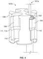
Fig. 4 shows a close-up view of the nest of the embodiment ofFig. 1 . - The applicant has developed a backshell configuration for managing fiber optic cables to ensure that the cables exiting the connector are held in a fixed state to avoid stress-related damage or diminished performance.
- In one embodiment, the present invention relates to an optical connector having a front and rear orientation and being configured for optically connecting a plurality of cables, each cable comprising one or more fibers terminated to a ferrule, each cable comprising a strength member and an eyelet crimped to the strength member, the connector comprising: (a) a connector housing; (b) a connector insert disposed in the connector housing and configured to receive a plurality of ferrules; and (c) a backshell, the backshell comprising at least the following, (i) a backshell housing configured to mechanically interengage with the connector housing; (ii) a nest having a periphery and a plurality of cavities, each cavity of the plurality of cavities having an opening to the periphery and being configured to receive the eyelet of each cable, the nest being configured to restrict axial movement of the eyelet when disposed in the cavity; (iii) a capture member mechanically interengaged with the backshell to hold the nest in a fixed position relative to the backshell housing; and wherein the nest is disposed between the capture member and the backshell housing such that the opening of each cavity is blocked by at least one of the capture member or the backshell housing to hold each eyelet in one of the cavities.
- In another embodiment, the present invention relates to a backshell for interengagement with an optical connector housing, the optical connector configured for optically connecting a plurality of cables, each cable comprising one or more fibers terminated in a ferrule, each cable comprising a strength member and an eyelet crimped to the strength member, the connector comprising a connector housing and a connector insert disposed in the connector housing and configured to receive a plurality of ferrules, the backshell comprising:
- (a) a backshell housing configured to mechanically interengage with the connector housing;
- (b) a nest having a periphery and a plurality of cavities, each cavity of the plurality of cavities having an opening to the periphery and being configured to receive the eyelet of each cable, the nest being configured to restrict axial movement of the eyelet when disposed in the cavity;
- (c) a capture member mechanically interengaged with the backshell to hold the nest in a fixed position relative to the backshell housing; and wherein the nest is disposed between the capture member and the backshell housing such that the opening of each cavity is blocked by at least one of the capture member or the backshell housing to hold each eyelet in one of the cavities.
- In yet another embodiment, the present invention relates to a method of assembling a plurality of cables in a connector, each cable comprising one or more fibers terminated to a ferrule, each cable comprising a strength member and an eyelet crimped to the strength member, the method comprising: (a) inserting the ferrule of each cable in a connector insert; (b) radially inserting the crimp eyelet of each cable in a cavity of a nest through an opening on the periphery of the nest; (c) while the crimp eyelets are disposed in the cavities of the nest, sliding the capture member over the nest thereby encircling the periphery of nest and blocking the peripheral openings, thereby closing the crimp eyelets in the cavities; and (d) connecting the capture member to the backshell housing such that the nest is sandwiched between the capture member and the backshell housing, thereby preventing its axial movement.
- Referring to
Figs. 1-4 , one embodiment of anoptical connector 100 of the present invention is shown. The optical connector has a front and rear orientation, and is configured for optically connecting a plurality of cables (onecable 101 is shown inFigs. 1-4 ). Eachcable 101 comprises one or more fibers, which are terminated to aferrule 102. Each cable also comprises astrength member 103 and aneyelet 104 crimped to the strength member. - In one embodiment, the connector comprises a
connector housing 105 and aconnector insert 106 disposed in the connector housing and configured to receive a plurality of ferrules, and abackshell 107. The backshell comprises abackshell housing 107a configured to mechanically interengaged with the connector housing, anest 107b, and acapture member 107c mechanically interengaged with the backshell housing to hold the nest in a fixed position relative to the backshell housing. - The nest has a
periphery 109 and defines a plurality ofcavities 108. Each cavity of the plurality of cavities defines anopening 110 at the periphery configured to receive the eyelet of a cable, and is configured to restrict axial movement of the eyelet when disposed in the cavity. The nest is disposed between the capture member and the backshell housing such that the opening of each cavity is blocked by at least one of the capture member or the backshell housing to hold each eyelet in one of the cavities. In the embodiment shown inFigs 1-4 , the capture member receives the nest and blocks the opening of each cavity. These features are described below in greater detail along with selected alternative embodiments. - The connector housing 105 and
insert 106 are well-known and conventional components and will not be described in detail herein. In this embodiment, the connector is a MIL D38999 circular connector, having a 4-cavity insert 106 and a Polamco SweptElbow backshell 107. It should be understood, however, that the backshell configuration of the present invention can be used with any multi-cavity connector. Additionally, although a circular connector is depicted herein, the connector need not be circular and may be, instead, rectangular. Likewise, the backshell configuration is not limited to an elbow, but can be configured in any shape, including straight and angled. Additionally, the backshell configuration is not limited in size and can be scaled up or down for any size connector -e.g., 11, 13, and 15 D38999 connectors. Likewise, although a circular insert having rectangular cavities to accommodate MT ferrules is shown, other embodiments are within the scope of the invention. For example, rather than MT ferrules, the insert may be configured to receive circular ferrules, which may be multifiber or single-fiber ferrules. Likewise, although an insert having four cavities is shown, an insert having fewer than four cavities or greater than four cavities may be used. - The
cable 101, including its optical fibers,strength member 103 andferrule 102, is also well known and will not be described in detail herein. Thecable 101 as shown is a conventional 4-24 fiber cable terminated with an MT ferrule, although any fiber-count cable, including a single fiber cable, may be used and terminated with any known ferrule. - The nest functions to secure the crimp eyelet, and thereby prevents movement of the
bare fiber 101a from the back of theconnector housing 105 to thenest 107b. As described above by restricting this movement, damage to thecable 101 is prevented. The nest secures the crimp eyelet by holding it within the cavity and preventing its axial movement through arestriction 111 which prevents the crimp eyelet from passing through. In one embodiment, the restriction is a narrowedportion 114 of nest cavity that prevents acrimp shoulder 115 from passing through as shown inFig. 4 . Other mechanisms for restricting movement of the crimp eyelet within nest include, for example, a clip or other fastener for holding the eyelet to the nest, a compression fit of the eyelet within the cavity, adhesive between the eyelet and the nest, and a magnetic attraction between the nest and the eyelet, just to name a few. - The crimp eyelet is received in the cavity through an
opening 110 at theperimeter 109 of thenest 107b as shown inFig. 4 . The openings along the perimeter of the nest facilitate easy radial insertion of the crimp eyelets in the cavities. In this particular embodiment, the nest is configured with four cavities to accommodate four crimp eyelets (and thus four cables). It should be understood, however, that other embodiments are possible and that fewer than four cavities or greater than four cavities may be defined in the nest. - In one embodiment, the backshell comprises a
capture member 107c for securing the nest. In one embodiment, thecapture member 107c has two functions. First, it functions to hold the crimp eyelets within the cavities. In one embodiment, thecapture member 107c is configured to receive the nest such that it can be slid over the nest once the crimp eyelets are in place to block the openings of the nest. As shown inFig. 3 , once thecapture member 107c is slid over thenest 107b such that the nest is disposed within thecapture member 107c, the openings around the perimeter of the nest are essentially closed/blocked, thereby securing the crimp eyelets within the cavities of the nest. - The
capture member 107c also functions to prevent the axial movement of the nest. In one embodiment, the nest is sandwiched between the capture member and the backshell housing. More specifically, in one embodiment, the backshell housing comprises aninner shoulder 113 against which the nest abuts when the capture member is connected to the backshell housing as shown inFig. 3 , thereby preventing the nest's forward axial movement (i.e., movement of the nest toward the connector insert). In this embodiment, the capture member comprises anouter shoulder 112 against which the nest abuts as shown inFig. 3 , thereby preventing the nest's rearward movement (i.e., movement of the nest away from the connector insert). - In one embodiment, the
capture member 107c threadably engages with threads on the rear portion of thebackshell housing 107a as shown inFig. 3 , although other means for connecting the capture member to the backshell housing exist -e.g., a snaping mechanism such as a resilient tab being received in an aperture or a resilient collet snaping over a ridge. Still other means of attachment will be obvious to those of skill in the art in the light of this disclosure. - As is known, in one embodiment, a
nut 116 is used to secure thebackshell housing 107a to the rear of theconnector housing 105 as shown inFig. 3 . In this embodiment,nut 116 threadably engages with the rear ofconnector housing 105. - Once the
connector assembly 100 is assembled as shown inFig. 3 , thenest 107b prevents movement of the stripped orbare fiber 101a between the rear of theconnector housing 105 and thenest 107b. Specifically, because the nest prevents the axial movement of the crimp eyelet, and the crimp eyelet is secured to thestrength member 103, any tension on thecable 101 exiting theconnector assembly 100 is borne by thenest 107b, and transferred to the backshell housing. Thus, no tension is transferred from thestrength member 103 of thecable 101 to thebare fiber 101a. - In one embodiment, as shown in
Fig. 2 , thebackshell housing 107a compriseskeys 220 configured to slot into one or more cavities of thenest 107b to prevent rotation of the nest relative to thebackshell housing 107a as the capture member is tightened onto thebackshell housing 107a. - As mentioned above, the unique configuration of the nest and the capture member provide an unprecedented ease of assembly of the connector assembly. In one embodiment, the method of assembly comprises: (a) inserting the
ferrule 102 of eachcable 101 in aconnector insert 106; (b) radially inserting thecrimp eyelet 104 of each cable in acavity 108 of thenest 107b through anopening 110 on theperiphery 109 of thenest 107b; (c) while the crimp eyelets are disposed in the cavities of the nest, sliding thecapture member 107c over the nest thereby encircling theperiphery 109 of nest and blocking theperipheral openings 110, thereby closing the crimp eyelets in the cavities; and (d) connecting thecapture member 107c to thebackshell housing 107a such that the nest is sandwiched between the capture member and the backshell housing, thereby preventing its axial movement. - In one embodiment, prior to step (a): the method comprises (i) stripping the cables to expose the bare fiber(s) 101a; (ii) terminating the fiber(s) of each cable with a
ferrule 102; (iii) crimping eyelets onto thestrength member 103 of the cable at the point where the fibers are stripped from the cable, and (iv) feeding the bare fiber(s) terminated with a ferrule through the backshell housing. In one embodiment, the cable comprises a plurality of fibers, and a ribbon is formed from stripped bare fibers to facilitate control and handling. - In one embodiment, prior to step (b): the method comprises (i) loading the ferrules into the
connector insert 106 and installing aretainer 106a; and (ii) positioning the backshell housing behind the connector housing and securing it thereto using a threadednut 116 as shown inFig. 3 .
Claims (15)
- An optical connector (100) having a front and rear orientation and being configured for optically connecting a plurality of cables (101), each cable (101) comprising one or more fibers (101a) terminated to a ferrule (102), each cable (101) comprising a strength member (103) and an eyelet (104) crimped to said strength member (103), said connector (100) comprising:a connector housing (105);a connector insert (106) disposed in said connector housing (105) and configured to receive a plurality of said ferrules (102);a backshell (107), said backshell (107) comprising at least the following,a backshell housing (107a) configured to mechanically interengage with said connector housing (105);a nest (107b) having a periphery (109) and a plurality of cavities (108), each cavity (108) of said plurality of cavities (108) having an opening (110) to said periphery (109) and being configured to receive said eyelet (104) of each cable, said nest (107b) being configured to restrict axial movement of said eyelet (104) when disposed in said cavity (108);a capture member (107c) mechanically interengaged with said backshell (107) to hold said nest (107b) in a fixed position relative to said backshell housing (107a); andwherein said nest (107b) is disposed between said capture member (107c) and said backshell housing (107a) such that said opening (110) of each cavity (108) is blocked by at least one of said capture member (107c) or said backshell housing (107a) to hold each eyelet (104) in one of said cavities (108).
- The optical connector (100) of claim 1, wherein said capture member (107c) receives said nest (107b) and blocks said opening (110) of each cavity (108).
- The optical connector (100) of claim 1 or 2, wherein said backshell housing (107a) comprises an inner shoulder (113) against which said nest (107b) abuts thereby preventing its forward axial movement, and wherein said capture member (107c) comprises an outer shoulder (112) against which said nest (107b) abuts thereby preventing its rearward movement.
- The optical connector (100) of any preceding claim, wherein each of said cavities (108) comprises a narrowed portion that prevents said eyelet (104) from passing through.
- The optical connector (100) of any preceding claim, wherein said ferrule (102) is an MT ferrule.
- The optical connector (100) of any preceding claim, wherein said plurality of cables (101) comprises four cables (101).
- The optical connector (100) of any preceding claim, wherein each cable (101) comprises a plurality of fibers (101a).
- The optical connector (100) of any preceding claim, wherein said capture member (107c) is in threaded engagement with said backshell (107).
- The optical connector (100) of any preceding claim, wherein said backshell (107) further comprises a nut (116) for threadedly engaging said connector housing (105).
- A backshell (107) for interengagement with an optical connector housing (105), the optical connector (100) configured for optically connecting a plurality of cables (101), each cable (101) comprising one or more fibers (101a) terminated in a ferrule (102), each cable (101) comprising a strength member (103) and an eyelet (104) crimped to the strength member (103), the connector comprising a connector housing (105) and a connector insert (106) disposed in the connector housing (105) and configured to receive a plurality of ferrules (102), the backshell (107) comprising:a backshell housing (107a) configured to mechanically interengage with said connector housing (105);a nest (107b) having a periphery (109) and a plurality of cavities (108), each cavity (108) of said plurality of cavities (108) having an opening (110) to said periphery (109) and being configured to receive said eyelet (104) of each cable (101), said nest (107b) being configured to restrict axial movement of said eyelet (104) when disposed in said cavity (108);a capture member (107c) mechanically interengaged with said backshell (107) to hold said nest (107b) in a fixed position relative to said backshell housing (107a); andwherein said nest (107b) is disposed between said capture member (107c) and said backshell housing (107a) such that said opening (110) of each cavity (108) is blocked by at least one of said capture member (107c) or said backshell housing (107a) to hold each eyelet (104) in one of said cavities (108).
- The backshell (107) of claim 10, wherein said capture member (107c) receives said nest (107b) and blocks said opening (110) of each cavity (108).
- The backshell (107) of claim 10 or 11, wherein said backshell housing (107a) comprises an inner shoulder (113) against which said nest (107b) abuts thereby preventing its forward axial movement, and wherein said capture member (107c) comprises an outer shoulder (112) against which said nest (107b) abuts thereby preventing its rearward movement.
- The backshell (107) of claim 10, 11 or 12 wherein each of said cavities (108) comprises a narrowed portion that prevents said eyelet (104) from passing through.
- The backshell (107) of any of claims 10 to 13, wherein the ferrule (102) is an MT ferrule.
- The backshell (107) of any of claims 10 to 14, wherein each cable (101) comprises a plurality of fibers (101a).
Applications Claiming Priority (1)
| Application Number | Priority Date | Filing Date | Title |
|---|---|---|---|
| US18/071,278 US12554073B2 (en) | 2022-11-29 | 2022-11-29 | Multi-cavity optical connector with cable management |
Publications (1)
| Publication Number | Publication Date |
|---|---|
| EP4394466A1 true EP4394466A1 (en) | 2024-07-03 |
Family
ID=89029645
Family Applications (1)
| Application Number | Title | Priority Date | Filing Date |
|---|---|---|---|
| EP23212881.9A Pending EP4394466A1 (en) | 2022-11-29 | 2023-11-29 | Multi-cavity optical connector with cable management |
Country Status (2)
| Country | Link |
|---|---|
| US (1) | US12554073B2 (en) |
| EP (1) | EP4394466A1 (en) |
Citations (3)
| Publication number | Priority date | Publication date | Assignee | Title |
|---|---|---|---|---|
| US5283848A (en) * | 1992-12-23 | 1994-02-01 | The Whitaker Corporation | Circular multi-fiber fiber-optic connector |
| US20140041212A1 (en) * | 2012-05-16 | 2014-02-13 | Optical Cable Corporation | Modular Back Shell Apparatus for Circular Connectors |
| US20190154922A1 (en) * | 2017-11-17 | 2019-05-23 | Commscope Technologies Llc | Fiber optic connector locking feature |
Family Cites Families (11)
| Publication number | Priority date | Publication date | Assignee | Title |
|---|---|---|---|---|
| US4373777A (en) * | 1980-08-11 | 1983-02-15 | International Telephone And Telegraph Corporation | Connector and cable assembly |
| US4516829A (en) * | 1982-05-12 | 1985-05-14 | International Telephone & Telegraph Corporation | Fiber optic contact retention assembly |
| US5048918A (en) * | 1990-02-07 | 1991-09-17 | Raychem Corporation | Optical fiber cable termination |
| US5074636A (en) * | 1990-06-21 | 1991-12-24 | Augat Communications Group, Inc. | Fiber optic cable entry connector |
| US5923802A (en) * | 1997-06-06 | 1999-07-13 | Siecor Corporation | Flexible connector assembly having slack storage |
| US5870515A (en) * | 1997-06-06 | 1999-02-09 | Siecor Corporation | Receptacle and associated method for permitting the selective withdrawal of a ferrule |
| US6398423B1 (en) * | 1999-12-15 | 2002-06-04 | Itt Manufacturing Enterprises, Inc. | Optic fiber retaining system |
| WO2014004549A2 (en) | 2012-06-27 | 2014-01-03 | Amgen Inc. | Anti-mesothelin binding proteins |
| EP3167321B1 (en) * | 2014-07-07 | 2020-09-02 | Commscope Technologies LLC | Optical ferrule for multi-fiber cable and hardened multi-fiber optic connector therefore |
| US11513298B2 (en) * | 2014-11-07 | 2022-11-29 | Ppc Broadband Fiber Ltd. | Preconnectorized multi-fiber drop cables and methods for deploying and assembling preconnectorized multi-fiber drop cables |
| US11226464B2 (en) * | 2019-03-07 | 2022-01-18 | Commscope Technologies Llc | Telecommunications fan-out arrangement |
-
2022
- 2022-11-29 US US18/071,278 patent/US12554073B2/en active Active
-
2023
- 2023-11-29 EP EP23212881.9A patent/EP4394466A1/en active Pending
Patent Citations (3)
| Publication number | Priority date | Publication date | Assignee | Title |
|---|---|---|---|---|
| US5283848A (en) * | 1992-12-23 | 1994-02-01 | The Whitaker Corporation | Circular multi-fiber fiber-optic connector |
| US20140041212A1 (en) * | 2012-05-16 | 2014-02-13 | Optical Cable Corporation | Modular Back Shell Apparatus for Circular Connectors |
| US20190154922A1 (en) * | 2017-11-17 | 2019-05-23 | Commscope Technologies Llc | Fiber optic connector locking feature |
Non-Patent Citations (1)
| Title |
|---|
| ANONYMOUS: "HexaShield High-Performance EMC/EMI Adaptors", 1 May 2003 (2003-05-01), pages 1 - 7, XP093340777, Retrieved from the Internet <URL:https://www.mouser.com/datasheet/2/418/4/NG_DS_1654507_0503-795674.pdf?srsltid=AfmBOoqgRgBNQm_U6iu-Q_Y7a4Z7DWcxggxQxijPAUZTs2HVTcbssD-h> [retrieved on 20251126] * |
Also Published As
| Publication number | Publication date |
|---|---|
| US20240176079A1 (en) | 2024-05-30 |
| US12554073B2 (en) | 2026-02-17 |
Similar Documents
| Publication | Publication Date | Title |
|---|---|---|
| US12013578B2 (en) | Multifiber fiber optic connectors, cable assemblies and methods of making the same | |
| US11105986B2 (en) | Ferrule housing with integrated boot | |
| US12436342B2 (en) | Fiber optic connectors and fiber optic connection systems | |
| US20210255411A1 (en) | Low cost hardened fiber optic connection system | |
| US8876407B2 (en) | Cable anchoring system | |
| EP2417485B1 (en) | Fiber optic connector | |
| EP0997757B1 (en) | Cylindrical connector incorporating a rectangular optical fibre ferrule | |
| CN1054919C (en) | Pull-proof, modular fiber optic connector system | |
| US4208092A (en) | Fiber optic multi-cable pair connector | |
| EP3167321B1 (en) | Optical ferrule for multi-fiber cable and hardened multi-fiber optic connector therefore | |
| CN112534325B (en) | Holding assembly for field-installable POF optical fiber with optical fiber assembly | |
| WO2020077299A1 (en) | Fiber splicing using a two-piece ferrule to form a mpo connector | |
| US12554073B2 (en) | Multi-cavity optical connector with cable management | |
| EP0024959B1 (en) | Connector for optical waveguides | |
| US20250264668A1 (en) | Adapters and optical assemblies for mating dissimilar optical connectors | |
| US11016247B2 (en) | Mechanical splice protective sleeve for securing a splice area formed by splicing a plural of optical fibers | |
| WO2026055656A1 (en) | Multi-fiber hardened fiber optic connection systems |
Legal Events
| Date | Code | Title | Description |
|---|---|---|---|
| PUAI | Public reference made under article 153(3) epc to a published international application that has entered the european phase |
Free format text: ORIGINAL CODE: 0009012 |
|
| STAA | Information on the status of an ep patent application or granted ep patent |
Free format text: STATUS: THE APPLICATION HAS BEEN PUBLISHED |
|
| AK | Designated contracting states |
Kind code of ref document: A1 Designated state(s): AL AT BE BG CH CY CZ DE DK EE ES FI FR GB GR HR HU IE IS IT LI LT LU LV MC ME MK MT NL NO PL PT RO RS SE SI SK SM TR |
|
| STAA | Information on the status of an ep patent application or granted ep patent |
Free format text: STATUS: REQUEST FOR EXAMINATION WAS MADE |
|
| 17P | Request for examination filed |
Effective date: 20250103 |
|
| STAA | Information on the status of an ep patent application or granted ep patent |
Free format text: STATUS: EXAMINATION IS IN PROGRESS |
|
| 17Q | First examination report despatched |
Effective date: 20251205 |