EP4394457A1 - X-ray inspection device - Google Patents
X-ray inspection device Download PDFInfo
- Publication number
- EP4394457A1 EP4394457A1 EP23219368.0A EP23219368A EP4394457A1 EP 4394457 A1 EP4394457 A1 EP 4394457A1 EP 23219368 A EP23219368 A EP 23219368A EP 4394457 A1 EP4394457 A1 EP 4394457A1
- Authority
- EP
- European Patent Office
- Prior art keywords
- ray
- cool air
- unit
- detection unit
- air blower
- Prior art date
- Legal status (The legal status is an assumption and is not a legal conclusion. Google has not performed a legal analysis and makes no representation as to the accuracy of the status listed.)
- Granted
Links
Images




Classifications
-
- G—PHYSICS
- G01—MEASURING; TESTING
- G01T—MEASUREMENT OF NUCLEAR OR X-RADIATION
- G01T7/00—Details of radiation-measuring instruments
-
- G—PHYSICS
- G01—MEASURING; TESTING
- G01N—INVESTIGATING OR ANALYSING MATERIALS BY DETERMINING THEIR CHEMICAL OR PHYSICAL PROPERTIES
- G01N23/00—Investigating or analysing materials by the use of wave or particle radiation, e.g. X-rays or neutrons, not covered by groups G01N3/00 – G01N17/00, G01N21/00 or G01N22/00
- G01N23/02—Investigating or analysing materials by the use of wave or particle radiation, e.g. X-rays or neutrons, not covered by groups G01N3/00 – G01N17/00, G01N21/00 or G01N22/00 by transmitting the radiation through the material
- G01N23/06—Investigating or analysing materials by the use of wave or particle radiation, e.g. X-rays or neutrons, not covered by groups G01N3/00 – G01N17/00, G01N21/00 or G01N22/00 by transmitting the radiation through the material and measuring the absorption
- G01N23/083—Investigating or analysing materials by the use of wave or particle radiation, e.g. X-rays or neutrons, not covered by groups G01N3/00 – G01N17/00, G01N21/00 or G01N22/00 by transmitting the radiation through the material and measuring the absorption the radiation being X-rays
-
- G—PHYSICS
- G01—MEASURING; TESTING
- G01N—INVESTIGATING OR ANALYSING MATERIALS BY DETERMINING THEIR CHEMICAL OR PHYSICAL PROPERTIES
- G01N23/00—Investigating or analysing materials by the use of wave or particle radiation, e.g. X-rays or neutrons, not covered by groups G01N3/00 – G01N17/00, G01N21/00 or G01N22/00
- G01N23/02—Investigating or analysing materials by the use of wave or particle radiation, e.g. X-rays or neutrons, not covered by groups G01N3/00 – G01N17/00, G01N21/00 or G01N22/00 by transmitting the radiation through the material
- G01N23/04—Investigating or analysing materials by the use of wave or particle radiation, e.g. X-rays or neutrons, not covered by groups G01N3/00 – G01N17/00, G01N21/00 or G01N22/00 by transmitting the radiation through the material and forming images of the material
-
- G—PHYSICS
- G01—MEASURING; TESTING
- G01V—GEOPHYSICS; GRAVITATIONAL MEASUREMENTS; DETECTING MASSES OR OBJECTS; TAGS
- G01V5/00—Prospecting or detecting by the use of ionising radiation, e.g. of natural or induced radioactivity
- G01V5/20—Detecting prohibited goods, e.g. weapons, explosives, hazardous substances, contraband or smuggled objects
- G01V5/22—Active interrogation, i.e. by irradiating objects or goods using external radiation sources, e.g. using gamma rays or cosmic rays
-
- G—PHYSICS
- G01—MEASURING; TESTING
- G01N—INVESTIGATING OR ANALYSING MATERIALS BY DETERMINING THEIR CHEMICAL OR PHYSICAL PROPERTIES
- G01N2223/00—Investigating materials by wave or particle radiation
- G01N2223/30—Accessories, mechanical or electrical features
- G01N2223/304—Accessories, mechanical or electrical features electric circuits, signal processing
-
- G—PHYSICS
- G01—MEASURING; TESTING
- G01N—INVESTIGATING OR ANALYSING MATERIALS BY DETERMINING THEIR CHEMICAL OR PHYSICAL PROPERTIES
- G01N2223/00—Investigating materials by wave or particle radiation
- G01N2223/30—Accessories, mechanical or electrical features
- G01N2223/31—Accessories, mechanical or electrical features temperature control
- G01N2223/3103—Accessories, mechanical or electrical features temperature control cooling, cryostats
-
- G—PHYSICS
- G01—MEASURING; TESTING
- G01N—INVESTIGATING OR ANALYSING MATERIALS BY DETERMINING THEIR CHEMICAL OR PHYSICAL PROPERTIES
- G01N2223/00—Investigating materials by wave or particle radiation
- G01N2223/60—Specific applications or type of materials
- G01N2223/643—Specific applications or type of materials object on conveyor
Definitions
- an X-ray inspection device 1 includes a housing 2, support legs 3, a conveyor 4, an X-ray irradiation unit 5, an X-ray detection unit 6, a display operation unit 7, a control unit (inspection unit) 8, and a cool air blower 9.
- the X-ray inspection device 1 generates an X-ray transmission image of an article G while conveying the article G, and conducts an inspection (e.g., an accommodated quantity inspection, a foreign matter contamination inspection, a missing part inspection, or a chip/crack inspection) of the article G on the basis of the X-ray transmission image.
- the X-ray irradiation unit 5 irradiates the article G conveyed by the conveyor 4 with X-rays.
- the X-ray irradiation unit 5 is provided with a fan 10 rearward of the X-ray irradiation unit 5.
- the X-ray detection unit 6 is configured as an X-ray detection module 13 in which a control board (not illustrated) is added to the sensor 11.
- the X-ray detection module 13 is accommodated in a sensor box 14.
- the sensor box 14 is a rectangular parallelepiped-shaped housing that accommodates the X-ray detection unit 6.
- a slit 14A is formed in an upper face of the sensor box 14. X-rays emitted from the X-ray irradiation unit 5 pass through the slit 14A.
- an opening 14B is provided on a front face of the sensor box 14.
- an opening 14C is provided on a rear face of the sensor box 14.
- the duct 16 is attached inside the housing 2.
- One end 16a of the duct 16 is connected to a supply port 9a of the cool air blower 9.
- the one end 16a of the duct 16 is open rearward.
- the one end 16a of the duct 16 is connected to the supply port 9a of the cool air blower 9 in a state in which the door 2a is closed.
- a fan (blower) 17 is provided between the supply port 9a of the cool air blower 9 and the one end 16a of the duct 16.
- the fan 17 delivers cool air supplied from the cool air blower 9 to the duct 16.
- the other end 16b of the duct 16 is connected to the accommodating portion 15.
- the X-ray inspection device 1 includes a discharge unit 19.
- the discharge unit 19 discharges water generated inside the housing 2 to outside of the housing 2.
- the discharge unit 19 is provided in the housing 2.
- the discharge unit 19 is disposed, for example, below the cool air blower 9.
- the discharge unit 19 is provided with a check valve 20.
- the check valve 20 prevents air outside the housing 2 from entering the housing 2 via the discharge unit 19.
- a sealing portion (not illustrated) is provided at a connection portion with the housing 2.
- the sealing portion is formed of a material such as rubber. The sealing portion can help prevent external air from flowing into the housing 2 from between the housing 2 and the discharge unit 19.
- the control unit 8 stops the operation of the fan 17. In other words, when an anomaly of the cool air blower 9 is detected, the control unit 8 stops flow of air to the X-ray detection unit 6.
- the control unit 8 stops the irradiation of X-rays by the X-ray irradiation unit 5 and the detection of X-rays by the X-ray detection unit 6.
- the control unit 8 resumes operation of each component (the conveyor 4, the X-ray irradiation unit 5, and the X-ray detection unit 6) in response to an operation by an operator on the display operation unit 7.
- the X-ray inspection device 1 As described above, in the X-ray inspection device 1 according to the present embodiment, when an anomaly of the cool air blower 9 is detected by the monitoring unit 18, the flow of air to the X-ray detection unit 6 is stopped. As a result, in the X-ray inspection device 1, when some kind of anomaly (malfunction) occurs in the cool air blower 9 and cool air cannot be supplied from the cool air blower 9, insufficiently cooled air (moisture-containing air) is not guided to the X-ray detection unit 6. Thus, in the X-ray inspection device 1, it is possible to suppress the occurrence of condensation on the X-ray detection unit 6 and other components. Accordingly, in the X-ray inspection device 1, it is possible to help prevent moisture generated from the condensation from entering the X-ray detection unit 6. As a result, in the X-ray inspection device 1, it is possible to suppress the occurrence of malfunction in the X-ray detection unit 6 in a configuration in which the X-ray detection unit 6 is cooled.
- the cool air blower 9 and the fan 17 are made to operate in conjunction with each other and the ambient temperature of the X-ray inspection device 1 is low, the operation of the fan 17 is stopped in conjunction with stopping the operation of the cool air blower 9. In this case, because the flow of air to the X-ray detection unit 6 (X-ray detection module 13) is stopped, the X-ray detection unit 6 may overheat.
- the cool air blower 9 and the fan 17 are operated independently. Thus, even if the operation of the cool air blower 9 is stopped, low-temperature air inside the housing 2 can be sent to the X-ray detection unit 6. This makes it possible to avoid the X-ray detection unit 6 overheating.
- the control unit 8 stops the irradiation of the X-rays by the X-ray irradiation unit 5 and the detection of the X-rays by the X-ray detection unit 6.
- the irradiation of X-rays by the X-ray irradiation unit 5 and the detection of X-rays by the X-ray detection unit 6 are stopped.
- the X-ray inspection device 1 includes the discharge unit 19 that discharges water generated inside the housing 2 to outside the housing 2.
- the discharge unit 19 includes the sealing portion and the check valve 20 that suppress the inflow of external air into the housing 2.
- the X-ray detection unit 6 may include a first line sensor 12a and a second line sensor 12b.
- Each of the first line sensor 12a and the second line sensor 12b is constituted by X-ray detection elements (not illustrated) arrayed one dimensionally in a horizontal direction perpendicular to the conveyance direction A.
- the first line sensor 12a detects X-rays in a low-energy band transmitted through the article G and the conveyor belt of the conveyor 4.
- the second line sensor 12b detects X-rays in a high-energy band transmitted through the article G, the conveyor belt of the conveyor 4, and the first line sensor 12a.
- a mode in which the X-ray detection unit 6 is configured as the X-ray detection module 13 is described as an example.
- the sensor 11 and the control board may be disposed at different positions.
- a mode in which the power source of the X-ray irradiation unit 5 is turned off to stop the irradiation of the X-rays by the X-ray irradiation unit 5 and the power source of the X-ray detection unit 6 is turned off to stop the detection of the X-rays by the X-ray detection unit 6 when an anomaly of the cool air blower 9 is detected by the monitoring unit 18 is described as an example.
- the irradiation of the X-rays by the X-ray irradiation unit 5 and the detection of the X-rays by the X-ray detection unit 6 need only be stopped.
- a mode in which conveyance of the article G by the conveyor 4 is stopped when an anomaly of the cool air blower 9 is detected by the monitoring unit 18 is described as an example.
- conveyance of the article G by the conveyor 4 may be continued.
- the article G may be left behind in the X-ray inspection device 1 and it may no longer be possible to determine whether the article G was inspected. Therefore, the article G may need to be disposed of, resulting in waste.
- the cool air blower 9 may be disposed in the interior of the housing 2. Further, the cool air may be supplied to the duct 16 from the cool air blower 9 disposed outside the housing 2 via a duct or the like.
Landscapes
- Physics & Mathematics (AREA)
- Health & Medical Sciences (AREA)
- General Physics & Mathematics (AREA)
- Life Sciences & Earth Sciences (AREA)
- Immunology (AREA)
- Biochemistry (AREA)
- General Health & Medical Sciences (AREA)
- Analytical Chemistry (AREA)
- Chemical & Material Sciences (AREA)
- Pathology (AREA)
- High Energy & Nuclear Physics (AREA)
- Toxicology (AREA)
- General Life Sciences & Earth Sciences (AREA)
- Geophysics (AREA)
- Molecular Biology (AREA)
- Spectroscopy & Molecular Physics (AREA)
- Analysing Materials By The Use Of Radiation (AREA)
Abstract
Description
- The present invention relates to an X-ray inspection device.
- An X-ray inspection device includes a conveyor that conveys an article, an X-ray irradiation unit that irradiates the article conveyed by the conveyor with an X-ray, and an X-ray detection unit that detects the X-ray transmitted through the article. The X-ray inspection device described in
Patent Document 1 includes an air guide unit that guides cool air supplied from a cool air blower to at least a portion of the X-ray detection unit via a duct to cool the X-ray detection unit. - Patent Document 1:
JP 2019-164088 A - In a configuration in which the X-ray detection unit is cooled as in the X-ray inspection device described above, cool air supplied from the cool air blower is dehumidified by heat exchange when the air is cooled. Therefore, the environment in which the X-ray detection unit to which the cool air is guided and members surrounding the X-ray detection unit (e.g., a sensor box) are disposed is in a state of low humidity (dry state). In this state, when a malfunction occurs in the cooling function or the like of the cool air blower and insufficiently cooled air (moisture-containing air) is guided to the X-ray detection unit which has a lowered temperature, condensation may occur on the X-ray detection unit or the members surrounding the X-ray detection unit. When water generated by the condensation enters the X-ray detection unit, a malfunction may occur in the X-ray detection unit.
- An aspect of the present invention is to provide an X-ray inspection device that can suppress the occurrence of malfunction in an X-ray detection unit in a configuration in which the X-ray detection unit is cooled.
-
- (1) An X-ray inspection device according to one aspect of the present invention includes a conveyor configured to convey an article, an X-ray irradiation unit configured to irradiate the article conveyed by the conveyor with an X-ray, an X-ray detection unit configured to detect the X-ray transmitted through the article, an inspection unit configured to generate an X-ray transmission image from the X-ray detected by the X-ray detection unit and inspect the article on the basis of the X-ray transmission image, a housing accommodating the X-ray irradiation unit and the X-ray detection unit, a cool air blower configured to cool air inside the housing and guide cool air to the X-ray detection unit via a duct, a monitoring unit configured to monitor a state of the cool air blower, and a control unit configured to stop the flow of air to the X-ray detection unit when an anomaly of the cool air blower is detected by the monitoring unit.
In the X-ray inspection device according to one aspect of the present invention, the flow of air to the X-ray detection unit is stopped when an anomaly of the cool air blower is detected by the monitoring unit. As a result, in the X-ray inspection device, when some kind of anomaly (malfunction) occurs in a cool air blower and cool air cannot be supplied from the cool air blower, insufficiently cooled air (moisture-containing air) is not guided to the X-ray detection unit. Thus, in the X-ray inspection device, it is possible to suppress the occurrence of condensation on the X-ray detection unit and other components. Accordingly, in the X-ray inspection device, it is possible to help prevent water formed by the condensation from entering the X-ray detection unit. As a result, in the X-ray inspection device, it is possible to suppress the occurrence of malfunction in the X-ray detection unit in a configuration in which the X-ray detection unit is cooled. - (2) In the X-ray inspection device according to (1) described above, the control unit may stop the irradiation of the X-ray by the X-ray irradiation unit and the detection of the X-ray by the X-ray detection unit when an anomaly of the cool air blower is detected by the monitoring unit. With this configuration, when an anomaly occurs in the cool air blower, the irradiation of the X-ray by the X-ray irradiation unit and the detection of the X-ray by the X-ray detection unit are stopped. Thus, it is possible to suppress a temperature rise inside the housing, and thus suppress overheating of the X-ray detection unit.
- (3) In the X-ray inspection device according to (1) or (2) described above, the control unit may continue the conveyance of the article by the conveyor when an anomaly of the cool air blower is detected by the monitoring unit. When operation of the conveyor is stopped due to the occurrence of an anomaly in the cool air blower, the article may be left behind in the X-ray inspection device and it may no longer be possible to determine whether the article was inspected. In this case, the article may need to be disposed of, resulting in waste. In the X-ray inspection device, when an anomaly of the cool air blower is detected by the monitoring unit, the conveyance of the article by the conveyor is continued. Accordingly, in the X-ray inspection device, it is possible to keep the article from being left behind in the X-ray inspection device, and thus avoid the generation of waste. Further, in the X-ray inspection device, by continuing the conveyance by the conveyor, it is possible to continue inspection until the X-ray detection unit reaches a predetermined temperature, for example, and troubleshoot the anomaly of the cool air blower during that time. Accordingly, the operation of a line in which the article is processed can continue.
- (4) The X-ray inspection device according to any one of (1) to (3) described above may further include a discharge unit configured to discharge water generated inside the housing to outside of the housing, the cool air blower may cool the air inside the housing by internal air circulation to generate the cool air, and the discharge unit may include a sealing portion and/or a check valve, the sealing portion and the check valve being configured to prevent external air from flowing into the housing. With this configuration, it is possible to help prevent high-temperature and humid air from flowing into the housing via the discharge unit. Accordingly, in the X-ray inspection device, it is possible to suppress the occurrence of condensation on the X-ray detection unit and other components caused by the air.
- (5) The X-ray inspection device according to any one of (1) to (4) described above may include a blower configured to blow the cool air supplied from the cool air blower to the duct, and the control unit may stop operation of the blower when an anomaly of the cool air blower is detected by the monitoring unit. With this configuration, it is possible to more reliably suppress the guidance of insufficiently cooled air to the X-ray detection unit.
- According to one aspect of the present invention, it is possible to suppress the occurrence of malfunction in an X-ray detection unit in a configuration in which the X-ray detection unit is cooled.
-
-
FIG. 1 is a perspective view illustrating an appearance of an X-ray inspection device according to an embodiment. -
FIG. 2 is a perspective view of the X-ray inspection device illustrated inFIG. 1 with a rear door open. -
FIG. 3 is a diagram illustrating the configuration of the X-ray inspection device inFIG. 1 from a side face side. -
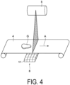
FIG. 4 is a perspective view illustrating a housing interior of the X-ray inspection device ofFIG. 1 . -
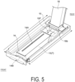
FIG. 5 is a perspective view illustrating an accommodating portion and a duct. -
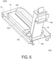
FIG. 6 is a perspective view illustrating the accommodating portion and the duct. -
FIG. 7 is a perspective view illustrating the accommodating portion. -
FIG. 8 is a perspective view of the housing interior of an X-ray inspection device according to another embodiment. - Preferred embodiments of the present invention will be described below in detail with reference to the attached drawings. Note that, in the description of the drawings, like or equivalent elements are denoted by the same reference signs and redundant descriptions thereof will be omitted. In
FIG. 1 ,FIG. 3 ,FIG. 5 , andFIG. 6 , "up", "down", "left", "right", "front", and "rear" are defined for convenience of description. However, the embodiments are not limited to these directions. - As illustrated in
FIG. 1 to FIG. 4 , anX-ray inspection device 1 includes ahousing 2,support legs 3, aconveyor 4, anX-ray irradiation unit 5, anX-ray detection unit 6, adisplay operation unit 7, a control unit (inspection unit) 8, and acool air blower 9. TheX-ray inspection device 1 generates an X-ray transmission image of an article G while conveying the article G, and conducts an inspection (e.g., an accommodated quantity inspection, a foreign matter contamination inspection, a missing part inspection, or a chip/crack inspection) of the article G on the basis of the X-ray transmission image. - The
housing 2 accommodates theconveyor 4, theX-ray irradiation unit 5, theX-ray detection unit 6, and thecontrol unit 8. In an interior of thehousing 2, an inspection region R is set where the article G is inspected with X-rays. Thesupport legs 3 support thehousing 2. Theconveyor 4 conveys the article G in a conveyance direction A. Theconveyor 4 is, for example, a belt conveyor. - The
X-ray irradiation unit 5 irradiates the article G conveyed by theconveyor 4 with X-rays. TheX-ray irradiation unit 5 is provided with afan 10 rearward of theX-ray irradiation unit 5. - The
X-ray detection unit 6 is asensor 11 that detects electromagnetic waves. TheX-ray detection unit 6 may be configured to detect an X-ray in a specific energy band or may be configured to detect an X-ray by a photon counting method. TheX-ray detection unit 6 may be a direct conversion type detection unit or an indirect conversion type detection unit. In the present embodiment, theX-ray detection unit 6 is a direct conversion type detection unit that can detect an X-ray by a photon counting method, and includes sensors (multi-energy sensors) that detect X-rays in each of a plurality of energy bands transmitted through the article G. The sensors are arranged linearly at least in a direction (width direction) orthogonal to the conveyance direction of theconveyor 4 and the up-down direction, for example. These elements may be arranged linearly not only in the width direction described above but also in the conveyance direction described above. That is, theX-ray detection unit 6 may include a line sensor or may include a sensor group disposed two dimensionally. Thesensor 11 is, for example, a photon detection type sensor such as a CdTe semiconductor detector. - In the present embodiment, the
X-ray detection unit 6 is configured as anX-ray detection module 13 in which a control board (not illustrated) is added to thesensor 11. TheX-ray detection module 13 is accommodated in asensor box 14. Thesensor box 14 is a rectangular parallelepiped-shaped housing that accommodates theX-ray detection unit 6. Aslit 14A is formed in an upper face of thesensor box 14. X-rays emitted from theX-ray irradiation unit 5 pass through theslit 14A. As illustrated inFIG. 5 , anopening 14B is provided on a front face of thesensor box 14. As illustrated inFIG. 6 andFIG. 7 , anopening 14C is provided on a rear face of thesensor box 14. - As illustrated in
FIG. 5 to FIG. 7 , thesensor box 14 is accommodated in anaccommodating portion 15. Theaccommodating portion 15 is disposed below theconveyor 4. Aflow path 15F for cool air supplied from thecool air blower 9 is formed in theaccommodating portion 15. The cool air is guided into theaccommodating portion 15 through aduct 16. Theduct 16 is connected to a rear portion of theaccommodating portion 15. - As illustrated in
FIG. 3 , thedisplay operation unit 7 is provided in thehousing 2. Thedisplay operation unit 7 displays various types of information and receives inputs for various conditions. Thedisplay operation unit 7 is, for example, a liquid crystal display and displays an operation screen as a touch panel. - As illustrated in
FIG. 3 , thecontrol unit 8 is disposed in the interior of thehousing 2. Thecontrol unit 8 controls the operation of each component of theX-ray inspection device 1. Thecontrol unit 8 includes a central processing unit (CPU), a read only memory (ROM), and a random access memory (RAM). Detection results of X-rays in the low energy band and the high energy band are input to thecontrol unit 8 from the sensors 11 (refer toFIG. 4 ) of theX-ray detection unit 6. Thecontrol unit 8 functions as an inspection unit that generates X-ray transmission images on the basis of the detection result of the X-ray in the low energy band and the detection result of the X-ray in the high energy band and inspects the article G on the basis of the X-ray transmission images. - As illustrated in
FIG. 1 andFIG. 2 , thecool air blower 9 is disposed on a rear face of theX-ray inspection device 1. In the present embodiment, thecool air blower 9 is attached to adoor 2a, with which thehousing 2 can be opened and closed. Thecool air blower 9 is, for example, a cooler. Thecool air blower 9 draws air into the interior of thehousing 2, and causes the drawn air to undergo heat exchange in a heat exchanger (not illustrated) to generate air cooled by the heat exchange (cool air). Thecool air blower 9 generates the cool air by internal air circulation. Thecool air blower 9 supplies the cool air to theaccommodating portion 15 via theduct 16. - The
duct 16 is attached inside thehousing 2. Oneend 16a of theduct 16 is connected to asupply port 9a of thecool air blower 9. The oneend 16a of theduct 16 is open rearward. The oneend 16a of theduct 16 is connected to thesupply port 9a of thecool air blower 9 in a state in which thedoor 2a is closed. A fan (blower) 17 is provided between thesupply port 9a of thecool air blower 9 and the oneend 16a of theduct 16. Thefan 17 delivers cool air supplied from thecool air blower 9 to theduct 16. Theother end 16b of theduct 16 is connected to theaccommodating portion 15. - As illustrated in
FIG. 3 , thecool air blower 9 includes amonitoring unit 18. Themonitoring unit 18 monitors the state of thecool air blower 9. Themonitoring unit 18 includes a CPU, a ROM, and a RAM. Themonitoring unit 18 is communicably connected to thecontrol unit 8. Themonitoring unit 18 accepts input of various types of information related to the operation of thecool air blower 9, monitors the state of thecool air blower 9, and detects an anomaly of thecool air blower 9. Themonitoring unit 18 detects, for example, a temperature anomaly of a temperature sensor (not illustrated) of thecool air blower 9 or a current anomaly of a compressor of thecool air blower 9. In a case where an anomaly is detected, themonitoring unit 18 outputs an error signal to thecontrol unit 8. - As illustrated in
FIG. 1 , theX-ray inspection device 1 includes adischarge unit 19. Thedischarge unit 19 discharges water generated inside thehousing 2 to outside of thehousing 2. Thedischarge unit 19 is provided in thehousing 2. Thedischarge unit 19 is disposed, for example, below thecool air blower 9. Thedischarge unit 19 is provided with acheck valve 20. Thecheck valve 20 prevents air outside thehousing 2 from entering thehousing 2 via thedischarge unit 19. In thedischarge unit 19, a sealing portion (not illustrated) is provided at a connection portion with thehousing 2. The sealing portion is formed of a material such as rubber. The sealing portion can help prevent external air from flowing into thehousing 2 from between thehousing 2 and thedischarge unit 19. - Next, the flow of the cool air supplied from the
cool air blower 9 will be described. The cool air supplied from thecool air blower 9 is supplied to theduct 16 from thesupply port 9a of thecool air blower 9. The cool air supplied to theduct 16 flows into theaccommodating portion 15. As illustrated inFIG. 3 ,FIG. 5 , andFIG. 6 , the cool air flowing into theaccommodating portion 15 flows from theopening 14C at the rear of thesensor box 14 to below thesensor box 14, flows frontward in theaccommodating portion 15, is partially discharged from theopening 14B, and partially flows rearward through a ventilation path at a lateral inner side defined by theaccommodating portion 15. The cool air flowing through theaccommodating portion 15 removes heat from theX-ray detection module 13 accommodated in thesensor box 14. Air that has risen in temperature (warm air) is discharged into thehousing 2 from the front left and right of theaccommodating portion 15 and from the rear of theaccommodating portion 15 through the ventilation path. - Next, the operation of the
X-ray inspection device 1 will be described. In theX-ray inspection device 1, when an error signal is output from themonitoring unit 18, that is, when an anomaly of thecool air blower 9 is detected, thecontrol unit 8 stops the operation of thefan 17. In other words, when an anomaly of thecool air blower 9 is detected, thecontrol unit 8 stops flow of air to theX-ray detection unit 6. When an error signal is output from themonitoring unit 18, thecontrol unit 8 stops the irradiation of X-rays by theX-ray irradiation unit 5 and the detection of X-rays by theX-ray detection unit 6. In the present embodiment, when an error signal is output from themonitoring unit 18, thecontrol unit 8 turns off the power source of theX-ray irradiation unit 5 and theX-ray detection unit 6. When an error signal is output from themonitoring unit 18, thecontrol unit 8 stops conveyance of the article G by theconveyor 4. In the present embodiment, when an error signal is output from themonitoring unit 18, thecontrol unit 8 turns off the power source of theconveyor 4. - In the
X-ray inspection device 1, for example, when the error of thecool air blower 9 is resolved, thecontrol unit 8 resumes operation of each component (theconveyor 4, theX-ray irradiation unit 5, and the X-ray detection unit 6) in response to an operation by an operator on thedisplay operation unit 7. - As described above, in the
X-ray inspection device 1 according to the present embodiment, when an anomaly of thecool air blower 9 is detected by themonitoring unit 18, the flow of air to theX-ray detection unit 6 is stopped. As a result, in theX-ray inspection device 1, when some kind of anomaly (malfunction) occurs in thecool air blower 9 and cool air cannot be supplied from thecool air blower 9, insufficiently cooled air (moisture-containing air) is not guided to theX-ray detection unit 6. Thus, in theX-ray inspection device 1, it is possible to suppress the occurrence of condensation on theX-ray detection unit 6 and other components. Accordingly, in theX-ray inspection device 1, it is possible to help prevent moisture generated from the condensation from entering theX-ray detection unit 6. As a result, in theX-ray inspection device 1, it is possible to suppress the occurrence of malfunction in theX-ray detection unit 6 in a configuration in which theX-ray detection unit 6 is cooled. - In the
X-ray inspection device 1, when thecool air blower 9 and thefan 17 are made to operate in conjunction with each other and the ambient temperature of theX-ray inspection device 1 is low, the operation of thefan 17 is stopped in conjunction with stopping the operation of thecool air blower 9. In this case, because the flow of air to the X-ray detection unit 6 (X-ray detection module 13) is stopped, theX-ray detection unit 6 may overheat. In theX-ray inspection device 1 according to the present embodiment, thecool air blower 9 and thefan 17 are operated independently. Thus, even if the operation of thecool air blower 9 is stopped, low-temperature air inside thehousing 2 can be sent to theX-ray detection unit 6. This makes it possible to avoid theX-ray detection unit 6 overheating. - In the
X-ray inspection device 1 according to the present embodiment, when an anomaly of thecool air blower 9 is detected by themonitoring unit 18, thecontrol unit 8 stops the irradiation of the X-rays by theX-ray irradiation unit 5 and the detection of the X-rays by theX-ray detection unit 6. With this configuration, when an anomaly occurs in thecool air blower 9, the irradiation of X-rays by theX-ray irradiation unit 5 and the detection of X-rays by theX-ray detection unit 6 are stopped. Thus, it is possible to suppress a temperature rise inside thehousing 2, and thus suppress overheating of theX-ray detection unit 6. - The
X-ray inspection device 1 according to the present embodiment includes thedischarge unit 19 that discharges water generated inside thehousing 2 to outside thehousing 2. Thedischarge unit 19 includes the sealing portion and thecheck valve 20 that suppress the inflow of external air into thehousing 2. With this configuration, it is possible to help prevent high temperature and humid air from flowing into thehousing 2 via thedischarge unit 19. Accordingly, in theX-ray inspection device 1, it is possible to suppress the occurrence of condensation on theX-ray detection unit 6 and other components caused by the air. - Although embodiments of the present invention have been described above, the present invention is not necessarily limited to the above-described embodiments, and various modifications can be made without departing from the gist of the present invention.
- In the embodiments described above, a mode in which the
X-ray detection unit 6 is a so-called photon-counting sensor is described as an example. However, as illustrated inFIG. 8 , theX-ray detection unit 6 may include afirst line sensor 12a and asecond line sensor 12b. Each of thefirst line sensor 12a and thesecond line sensor 12b is constituted by X-ray detection elements (not illustrated) arrayed one dimensionally in a horizontal direction perpendicular to the conveyance direction A. Thefirst line sensor 12a detects X-rays in a low-energy band transmitted through the article G and the conveyor belt of theconveyor 4. Thesecond line sensor 12b detects X-rays in a high-energy band transmitted through the article G, the conveyor belt of theconveyor 4, and thefirst line sensor 12a. - In the embodiments and modified examples described above, a mode in which the
X-ray detection unit 6 is configured as theX-ray detection module 13 is described as an example. However, thesensor 11 and the control board may be disposed at different positions. - In the embodiments and modified examples described above, a mode in which the power source of the
X-ray irradiation unit 5 is turned off to stop the irradiation of the X-rays by theX-ray irradiation unit 5 and the power source of theX-ray detection unit 6 is turned off to stop the detection of the X-rays by theX-ray detection unit 6 when an anomaly of thecool air blower 9 is detected by themonitoring unit 18 is described as an example. However, in theX-ray inspection device 1, when an anomaly of thecool air blower 9 is detected by themonitoring unit 18, the irradiation of the X-rays by theX-ray irradiation unit 5 and the detection of the X-rays by theX-ray detection unit 6 need only be stopped. - In the embodiments and modified examples described above, a mode in which conveyance of the article G by the
conveyor 4 is stopped when an anomaly of thecool air blower 9 is detected by themonitoring unit 18 is described as an example. However, when an anomaly of thecool air blower 9 is detected by themonitoring unit 18, conveyance of the article G by theconveyor 4 may be continued. When operation of theconveyor 4 is stopped due to the occurrence of an anomaly in thecool air blower 9, the article G may be left behind in theX-ray inspection device 1 and it may no longer be possible to determine whether the article G was inspected. Therefore, the article G may need to be disposed of, resulting in waste. In a configuration in which conveyance of the article G by theconveyor 4 is continued when an anomaly of thecool air blower 9 is detected by themonitoring unit 18, it is possible to keep the article G from being left behind in theX-ray inspection device 1, and thus avoid the occurrence of waste. Further, in theX-ray inspection device 1, by continuing conveyance by theconveyor 4, it is possible to continue inspection until theX-ray detection unit 6 reaches a predetermined temperature, for example, and troubleshoot the anomaly of thecool air blower 9 during that time. Accordingly, in theX-ray inspection device 1, operation of a line in which the article G is processed can continue. - In the embodiments and modified examples described above, a mode in which the
cool air blower 9 is provided on thedoor 2a with which thehousing 2 can be opened and closed is described as an example. However, thecool air blower 9 may be disposed in the interior of thehousing 2. Further, the cool air may be supplied to theduct 16 from thecool air blower 9 disposed outside thehousing 2 via a duct or the like. -
- 1 X-ray inspection device
- 2 Housing
- 4 Conveyor
- 5 X-ray irradiation unit
- 6 X-ray detection unit
- 8 Control unit (inspection unit)
- 9 Cool air blower
- 13 X-ray detection module
- 16 Duct
- 18 Monitoring unit
- 19 Discharge unit
- 20 Check valve
- G Article
Claims (5)
- An X-ray inspection device (1) comprising:a conveyor (4) configured to convey an article (G);an X-ray irradiation unit (5) configured to irradiate the article (G) conveyed by the conveyor (4) with an X-ray;an X-ray detection unit (6) configured to detect the X-ray transmitted through the article (G);an inspection unit configured to generate an X-ray transmission image from the X-ray detected by the X-ray detection unit (6) and inspect the article (G) on the basis of the X-ray transmission image;a housing (2) accommodating the X-ray irradiation unit (5) and the X-ray detection unit (6);a cool air blower (9) configured to cool air inside the housing (2) and guide cool air to the X-ray detection unit (6) via a duct (16);a monitoring unit (18) configured to monitor a state of the cool air blower (9); anda control unit (8) configured to stop the flow of air to the X-ray detection unit (6) when an anomaly of the cool air blower (9) is detected by the monitoring unit (18).
- The X-ray inspection device (1) according to claim 1,
wherein the control unit (8) stops the irradiation of the X-ray by the X-ray irradiation unit (5) and the detection of the X-ray by the X-ray detection unit (6) when an anomaly of the cool air blower (9) is detected by the monitoring unit (18). - The X-ray inspection device (1) according to claim 1 or 2,
wherein the control unit (8) continues the conveyance of the article (G) by the conveyor (4) when an anomaly of the cool air blower (9) is detected by the monitoring unit (18). - The X-ray inspection device (1) according to claim 1 or 2, further comprisinga discharge unit (19) configured to discharge water generated inside the housing (2) to outside of the housing (2),wherein the cool air blower (9) cools the air inside the housing (2) by internal air circulation to generate the cool air, andthe discharge unit (19) includes a sealing portion and/or a check valve (20), the sealing portion and the check valve (20) being configured to prevent external air from flowing into the housing (2).
- The X-ray inspection device (1) according to claim 1 or 2, further comprisinga blower (17) configured to blow the cool air supplied from the cool air blower (9) to the duct (16),wherein the control unit (8) stops operation of the blower (17) when an anomaly of the cool air blower (9) is detected by the monitoring unit (18).
Applications Claiming Priority (1)
| Application Number | Priority Date | Filing Date | Title |
|---|---|---|---|
| JP2022212447A JP2024095280A (en) | 2022-12-28 | 2022-12-28 | X-ray inspection equipment |
Publications (2)
| Publication Number | Publication Date |
|---|---|
| EP4394457A1 true EP4394457A1 (en) | 2024-07-03 |
| EP4394457B1 EP4394457B1 (en) | 2026-03-18 |
Family
ID=89308340
Family Applications (1)
| Application Number | Title | Priority Date | Filing Date |
|---|---|---|---|
| EP23219368.0A Active EP4394457B1 (en) | 2022-12-28 | 2023-12-21 | X-ray inspection device |
Country Status (3)
| Country | Link |
|---|---|
| US (1) | US12467885B2 (en) |
| EP (1) | EP4394457B1 (en) |
| JP (1) | JP2024095280A (en) |
Cited By (1)
| Publication number | Priority date | Publication date | Assignee | Title |
|---|---|---|---|---|
| EP4425220A1 (en) * | 2023-02-28 | 2024-09-04 | Ishida Co., Ltd. | X-ray inspection apparatus |
Families Citing this family (3)
| Publication number | Priority date | Publication date | Assignee | Title |
|---|---|---|---|---|
| USD1079007S1 (en) * | 2022-02-14 | 2025-06-10 | Delta Electronics, Inc. | X-ray security machine |
| WO2026048280A1 (en) * | 2024-08-27 | 2026-03-05 | 株式会社島津製作所 | X-ray analysis device |
| USD1121820S1 (en) * | 2024-09-26 | 2026-04-07 | Sstlabs Co., Ltd. | Computed tomography scanning device |
Citations (2)
| Publication number | Priority date | Publication date | Assignee | Title |
|---|---|---|---|---|
| JP5184848B2 (en) * | 2007-08-31 | 2013-04-17 | 株式会社東芝 | X-ray CT system |
| JP2019164088A (en) | 2018-03-20 | 2019-09-26 | 株式会社イシダ | X-ray inspection device |
-
2022
- 2022-12-28 JP JP2022212447A patent/JP2024095280A/en active Pending
-
2023
- 2023-12-13 US US18/539,236 patent/US12467885B2/en active Active
- 2023-12-21 EP EP23219368.0A patent/EP4394457B1/en active Active
Patent Citations (3)
| Publication number | Priority date | Publication date | Assignee | Title |
|---|---|---|---|---|
| JP5184848B2 (en) * | 2007-08-31 | 2013-04-17 | 株式会社東芝 | X-ray CT system |
| JP2019164088A (en) | 2018-03-20 | 2019-09-26 | 株式会社イシダ | X-ray inspection device |
| US20190297717A1 (en) * | 2018-03-20 | 2019-09-26 | Ishida Co., Ltd. | X-ray inspection apparatus |
Cited By (1)
| Publication number | Priority date | Publication date | Assignee | Title |
|---|---|---|---|---|
| EP4425220A1 (en) * | 2023-02-28 | 2024-09-04 | Ishida Co., Ltd. | X-ray inspection apparatus |
Also Published As
| Publication number | Publication date |
|---|---|
| EP4394457B1 (en) | 2026-03-18 |
| US20240219324A1 (en) | 2024-07-04 |
| JP2024095280A (en) | 2024-07-10 |
| US12467885B2 (en) | 2025-11-11 |
Similar Documents
| Publication | Publication Date | Title |
|---|---|---|
| EP4394457B1 (en) | X-ray inspection device | |
| JP7808339B2 (en) | X-ray inspection equipment | |
| US20240288592A1 (en) | X-ray inspection apparatus | |
| US9865424B2 (en) | X-ray inspection system | |
| JP2019164088A5 (en) | ||
| JP5364302B2 (en) | X-ray foreign object detection device | |
| WO2009157121A1 (en) | X-ray inspection apparatus | |
| JP5848941B2 (en) | X-ray inspection equipment | |
| JP6285987B2 (en) | Foreign matter inspection device | |
| JP3172652U (en) | X-ray inspection equipment | |
| CN115112688B (en) | X-ray inspection equipment | |
| JP6705433B2 (en) | Detector | |
| JP7611119B2 (en) | X-ray inspection equipment | |
| JP6157775B1 (en) | Foreign matter inspection apparatus and foreign matter inspection system | |
| JP7153525B2 (en) | X-ray inspection device | |
| JP6654393B2 (en) | Foreign matter inspection device | |
| JP6122926B2 (en) | Foreign matter inspection device | |
| JP6619607B2 (en) | X-ray inspection equipment | |
| JP6859276B2 (en) | X-ray inspection equipment | |
| JP6123005B2 (en) | Foreign matter inspection device | |
| CN119915847A (en) | X-ray inspection apparatus | |
| WO2017057740A1 (en) | Foreign matter inspection device | |
| JP2011102717A (en) | X-ray inspection apparatus |
Legal Events
| Date | Code | Title | Description |
|---|---|---|---|
| PUAI | Public reference made under article 153(3) epc to a published international application that has entered the european phase |
Free format text: ORIGINAL CODE: 0009012 |
|
| STAA | Information on the status of an ep patent application or granted ep patent |
Free format text: STATUS: REQUEST FOR EXAMINATION WAS MADE |
|
| 17P | Request for examination filed |
Effective date: 20231221 |
|
| AK | Designated contracting states |
Kind code of ref document: A1 Designated state(s): AL AT BE BG CH CY CZ DE DK EE ES FI FR GB GR HR HU IE IS IT LI LT LU LV MC ME MK MT NL NO PL PT RO RS SE SI SK SM TR |
|
| GRAP | Despatch of communication of intention to grant a patent |
Free format text: ORIGINAL CODE: EPIDOSNIGR1 |
|
| STAA | Information on the status of an ep patent application or granted ep patent |
Free format text: STATUS: GRANT OF PATENT IS INTENDED |
|
| INTG | Intention to grant announced |
Effective date: 20251023 |
|
| GRAS | Grant fee paid |
Free format text: ORIGINAL CODE: EPIDOSNIGR3 |
|
| GRAA | (expected) grant |
Free format text: ORIGINAL CODE: 0009210 |
|
| STAA | Information on the status of an ep patent application or granted ep patent |
Free format text: STATUS: THE PATENT HAS BEEN GRANTED |
|
| AK | Designated contracting states |
Kind code of ref document: B1 Designated state(s): AL AT BE BG CH CY CZ DE DK EE ES FI FR GB GR HR HU IE IS IT LI LT LU LV MC ME MK MT NL NO PL PT RO RS SE SI SK SM TR |
|
| REG | Reference to a national code |
Ref country code: CH Ref legal event code: F10 Free format text: ST27 STATUS EVENT CODE: U-0-0-F10-F00 (AS PROVIDED BY THE NATIONAL OFFICE) Effective date: 20260318 Ref country code: GB Ref legal event code: FG4D |
|
| REG | Reference to a national code |
Ref country code: IE Ref legal event code: FG4D |
|
| REG | Reference to a national code |
Ref country code: DE Ref legal event code: R096 Ref document number: 602023013677 Country of ref document: DE |