EP4394431A1 - Infrastructure-assisted signalling and sensing systems - Google Patents
Infrastructure-assisted signalling and sensing systems Download PDFInfo
- Publication number
- EP4394431A1 EP4394431A1 EP23215730.5A EP23215730A EP4394431A1 EP 4394431 A1 EP4394431 A1 EP 4394431A1 EP 23215730 A EP23215730 A EP 23215730A EP 4394431 A1 EP4394431 A1 EP 4394431A1
- Authority
- EP
- European Patent Office
- Prior art keywords
- interest
- region
- approaching object
- environmental information
- sensing
- Prior art date
- Legal status (The legal status is an assumption and is not a legal conclusion. Google has not performed a legal analysis and makes no representation as to the accuracy of the status listed.)
- Granted
Links
Images


Classifications
-
- G—PHYSICS
- G01—MEASURING; TESTING
- G01S—RADIO DIRECTION-FINDING; RADIO NAVIGATION; DETERMINING DISTANCE OR VELOCITY BY USE OF RADIO WAVES; LOCATING OR PRESENCE-DETECTING BY USE OF THE REFLECTION OR RERADIATION OF RADIO WAVES; ANALOGOUS ARRANGEMENTS USING OTHER WAVES
- G01S13/00—Systems using the reflection or reradiation of radio waves, e.g. radar systems; Analogous systems using reflection or reradiation of waves whose nature or wavelength is irrelevant or unspecified
- G01S13/86—Combinations of radar systems with non-radar systems, e.g. sonar, direction finder
-
- G—PHYSICS
- G01—MEASURING; TESTING
- G01S—RADIO DIRECTION-FINDING; RADIO NAVIGATION; DETERMINING DISTANCE OR VELOCITY BY USE OF RADIO WAVES; LOCATING OR PRESENCE-DETECTING BY USE OF THE REFLECTION OR RERADIATION OF RADIO WAVES; ANALOGOUS ARRANGEMENTS USING OTHER WAVES
- G01S7/00—Details of systems according to groups G01S13/00, G01S15/00, G01S17/00
- G01S7/003—Transmission of data between radar, sonar or lidar systems and remote stations
-
- G—PHYSICS
- G01—MEASURING; TESTING
- G01S—RADIO DIRECTION-FINDING; RADIO NAVIGATION; DETERMINING DISTANCE OR VELOCITY BY USE OF RADIO WAVES; LOCATING OR PRESENCE-DETECTING BY USE OF THE REFLECTION OR RERADIATION OF RADIO WAVES; ANALOGOUS ARRANGEMENTS USING OTHER WAVES
- G01S13/00—Systems using the reflection or reradiation of radio waves, e.g. radar systems; Analogous systems using reflection or reradiation of waves whose nature or wavelength is irrelevant or unspecified
- G01S13/02—Systems using reflection of radio waves, e.g. primary radar systems; Analogous systems
- G01S13/50—Systems of measurement based on relative movement of target
- G01S13/58—Velocity or trajectory determination systems; Sense-of-movement determination systems
- G01S13/583—Velocity or trajectory determination systems; Sense-of-movement determination systems using transmission of continuous unmodulated waves, amplitude-, frequency-, or phase-modulated waves and based upon the Doppler effect resulting from movement of targets
- G01S13/584—Velocity or trajectory determination systems; Sense-of-movement determination systems using transmission of continuous unmodulated waves, amplitude-, frequency-, or phase-modulated waves and based upon the Doppler effect resulting from movement of targets adapted for simultaneous range and velocity measurements
-
- G—PHYSICS
- G01—MEASURING; TESTING
- G01S—RADIO DIRECTION-FINDING; RADIO NAVIGATION; DETERMINING DISTANCE OR VELOCITY BY USE OF RADIO WAVES; LOCATING OR PRESENCE-DETECTING BY USE OF THE REFLECTION OR RERADIATION OF RADIO WAVES; ANALOGOUS ARRANGEMENTS USING OTHER WAVES
- G01S13/00—Systems using the reflection or reradiation of radio waves, e.g. radar systems; Analogous systems using reflection or reradiation of waves whose nature or wavelength is irrelevant or unspecified
- G01S13/88—Radar or analogous systems specially adapted for specific applications
- G01S13/91—Radar or analogous systems specially adapted for specific applications for traffic control
-
- G—PHYSICS
- G01—MEASURING; TESTING
- G01S—RADIO DIRECTION-FINDING; RADIO NAVIGATION; DETERMINING DISTANCE OR VELOCITY BY USE OF RADIO WAVES; LOCATING OR PRESENCE-DETECTING BY USE OF THE REFLECTION OR RERADIATION OF RADIO WAVES; ANALOGOUS ARRANGEMENTS USING OTHER WAVES
- G01S13/00—Systems using the reflection or reradiation of radio waves, e.g. radar systems; Analogous systems using reflection or reradiation of waves whose nature or wavelength is irrelevant or unspecified
- G01S13/88—Radar or analogous systems specially adapted for specific applications
- G01S13/93—Radar or analogous systems specially adapted for specific applications for anti-collision purposes
- G01S13/931—Radar or analogous systems specially adapted for specific applications for anti-collision purposes of land vehicles
-
- G—PHYSICS
- G01—MEASURING; TESTING
- G01S—RADIO DIRECTION-FINDING; RADIO NAVIGATION; DETERMINING DISTANCE OR VELOCITY BY USE OF RADIO WAVES; LOCATING OR PRESENCE-DETECTING BY USE OF THE REFLECTION OR RERADIATION OF RADIO WAVES; ANALOGOUS ARRANGEMENTS USING OTHER WAVES
- G01S7/00—Details of systems according to groups G01S13/00, G01S15/00, G01S17/00
- G01S7/003—Transmission of data between radar, sonar or lidar systems and remote stations
- G01S7/006—Transmission of data between radar, sonar or lidar systems and remote stations using shared front-end circuitry, e.g. antennas
-
- G—PHYSICS
- G08—SIGNALLING
- G08G—TRAFFIC CONTROL SYSTEMS
- G08G1/00—Traffic control systems for road vehicles
- G08G1/01—Detecting movement of traffic to be counted or controlled
- G08G1/056—Detecting movement of traffic to be counted or controlled with provision for distinguishing direction of travel
-
- H—ELECTRICITY
- H04—ELECTRIC COMMUNICATION TECHNIQUE
- H04W—WIRELESS COMMUNICATION NETWORKS
- H04W4/00—Services specially adapted for wireless communication networks; Facilities therefor
- H04W4/30—Services specially adapted for particular environments, situations or purposes
- H04W4/40—Services specially adapted for particular environments, situations or purposes for vehicles, e.g. vehicle-to-pedestrians [V2P]
-
- G—PHYSICS
- G01—MEASURING; TESTING
- G01S—RADIO DIRECTION-FINDING; RADIO NAVIGATION; DETERMINING DISTANCE OR VELOCITY BY USE OF RADIO WAVES; LOCATING OR PRESENCE-DETECTING BY USE OF THE REFLECTION OR RERADIATION OF RADIO WAVES; ANALOGOUS ARRANGEMENTS USING OTHER WAVES
- G01S13/00—Systems using the reflection or reradiation of radio waves, e.g. radar systems; Analogous systems using reflection or reradiation of waves whose nature or wavelength is irrelevant or unspecified
- G01S13/02—Systems using reflection of radio waves, e.g. primary radar systems; Analogous systems
- G01S13/06—Systems determining position data of a target
- G01S13/42—Simultaneous measurement of distance and other co-ordinates
-
- G—PHYSICS
- G01—MEASURING; TESTING
- G01S—RADIO DIRECTION-FINDING; RADIO NAVIGATION; DETERMINING DISTANCE OR VELOCITY BY USE OF RADIO WAVES; LOCATING OR PRESENCE-DETECTING BY USE OF THE REFLECTION OR RERADIATION OF RADIO WAVES; ANALOGOUS ARRANGEMENTS USING OTHER WAVES
- G01S13/00—Systems using the reflection or reradiation of radio waves, e.g. radar systems; Analogous systems using reflection or reradiation of waves whose nature or wavelength is irrelevant or unspecified
- G01S13/88—Radar or analogous systems specially adapted for specific applications
- G01S13/93—Radar or analogous systems specially adapted for specific applications for anti-collision purposes
- G01S13/931—Radar or analogous systems specially adapted for specific applications for anti-collision purposes of land vehicles
- G01S2013/9316—Radar or analogous systems specially adapted for specific applications for anti-collision purposes of land vehicles combined with communication equipment with other vehicles or with base stations
-
- G—PHYSICS
- G08—SIGNALLING
- G08G—TRAFFIC CONTROL SYSTEMS
- G08G1/00—Traffic control systems for road vehicles
- G08G1/01—Detecting movement of traffic to be counted or controlled
- G08G1/04—Detecting movement of traffic to be counted or controlled using optical or ultrasonic detectors
-
- G—PHYSICS
- G08—SIGNALLING
- G08G—TRAFFIC CONTROL SYSTEMS
- G08G1/00—Traffic control systems for road vehicles
- G08G1/01—Detecting movement of traffic to be counted or controlled
- G08G1/052—Detecting movement of traffic to be counted or controlled with provision for determining speed or overspeed
Definitions
- Joint communication and sensing systems share a single hardware platform and balance available resources spent on communication signals and signal processing and radar signals and signal processing.
- Base stations may perform radar sensing to obtain information about the surrounding environment and communicate the information about the environment to nearby user devices.
- base stations can perform radar sensing to obtain information about the surrounding environment.
- the techniques and methods described herein enable base stations to operate in a reactive or proactive mode of operation to provide relevant environmental information to nearby objects in a timely manner.
- the base station obtains an indication of an approaching object, such as by receiving an information request from the approaching object.
- the information request can include a region of interest for the approaching object, a reaction time for the approaching object, and the like.
- the base station performs radar sensing of the region of interest to obtain environmental information and transmits the environment information to a communication system of the approaching object, for example within the reaction time for the approaching object.
- the base station performs radar sensing of a known region of interest at intervals over time, such as once every minute or during low bandwidth requirements on the communication resources of the base station.
- the base station obtains an indication of an approaching object, such as by determining a location of the approaching object relative to the region of interest, and transmits the most current environmental information to a communication system of the approaching object.
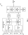
- FIG. 1 shows, in block diagram form, an example radar transceiver system 100, according to an embodiment.
- Radar system 100 can be included in a user device, for example a vehicle's driver assistance system, or in a communication base station.
- the example radar system 100 is a frequency-modulated continuous wave (FMCW) radar system, also referred to as a continuous-wave frequency-modulated (CWFM) radar, and capable of determining the distance or range, velocity, and angle of arrival of an object in the field of view of radar system 100.
- FMCW frequency-modulated continuous wave
- CWFM continuous-wave frequency-modulated
- radar system 100 is described herein as a linear chirp radar system, any appropriate radar system that generates at least one of range, Doppler, and angle of arrival information can be used, such as orthogonal frequency-domain multiplexing, polyphase sequencing, binary sequencing, Zadoff-Chu sequencing, and the like.
- radar system 100 includes a microcontroller and processor unit (MCPU) 110, a digital-to-analog converter (DAC) 120, a radar sensor circuit 130, a first antenna array 145, a second antenna array 150, an analog-to-digital converter (ADC) 170, and storage 180.
- the radar sensor circuit 130 is a radar transceiver circuit in this example, and includes both transmitter and receiver signal chains.
- the MCPU 110 comprises one or more MCPU cores, general purpose processing cores, field-programmable gate arrays, digital signal processors, application-specific integrated circuits, and the like, or any combination thereof.
- MCPU in the singular is used herein to refer to either a single or multiple of the MCPU cores, general purpose processing cores, field-programmable gate arrays, digital signal processors, application-specific integrated circuits, and the like, or any combination thereof comprised in the MCPU 110.
- the MCPU 110 includes a radar controller 115 and a signal processor 175.
- the radar controller 115 can receive data from the radar sensor circuit 130 and control radar parameters of the radar sensor circuit 130 such as frequency band, length of a radar frame, and the like via the DAC 120.
- a control signal from DAC 120 can be used to adjust the radar sensing signals output from a sensing signal generator 135 included in the radar sensor circuit 130.
- the signal processor 175 in MCPU 110 can also receive the data from the radar sensor circuit 130 and perform signal processing for determining a distance or range between a target object and radar system 100, a velocity of the target object, an angle of arrival for the target object, and the like.
- the signal processor 175 can provide the calculated values to the storage 180 and/or to other systems via the interface 190.
- the second antenna array 150 comprises one or more receiver (RX) antennas and receives signals reflected from objects in the path of the transmitted chirp signals from the TX antenna array 145.
- the TX antenna array 145 and the RX antenna array 150 can be stationary or configured to transmit and receive across a range of area, such as by mechanical movement.
- Frequency differences between the received reflections and the transmitted sensing signal increase with delay and so are proportional to distance.
- the phase differences between the received reflections across consecutive chirps in a radar frame are indicative of the velocity of objects in the field of view.
- the phase difference between received reflections at a first RX antenna and received reflections at a second RX antenna can be used to determine the angle of arrival of target objects.
- the down-converted and digitized receive signal corresponding to each chirp is first transformed using an FFT (called the range FFT).
- the range FFT produces a series of range bins with the value of each range bin denoting the signal strength of reflected targets at the corresponding range.
- a Doppler FFT is then performed for each range bin across all the chirps in a frame to estimate the velocities of reflected targets. Additional processing can then be performed to determine the angle of arrival between the targets and the radar system 100.
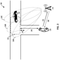
- FIG. 2 shows a diagram 200 of an example base station 210 operating in a reactive sensing mode of operation in an example environment, according to one embodiment.
- the base station 210 includes the radar transceiver system 100 shown in FIG. 1
- an approaching object 230 is a vehicle that includes a communication system.
- the approaching object 230 transmits an information request signal 250 to the base station 210 as it approaches along the road.
- the information request signal 250 can include an indicator of a region of interest to the approaching object 230, such as the intersection included in the region of interest 220, a reaction time for the approaching object 230, or both.
- the reaction time for the approaching object 230 can indicate an amount of time before the approaching object 230 reaches the region of interest 220 and thus, an amount of time in which the base station 210 can perform radar sensing of the region of interest 220 and provide the environmental information about the region of interest 220 to the approaching object 230.
- the base station 210 can perform radar sensing of the region of interest 220 to obtain environmental information, such as objects detected in the region of interest 220 and corresponding velocities and angles of arrival for the detected objects. That is, in a reactive sensing mode of operation, the base station 210 performs radar sensing in response to receiving an information request signal 250.
- the region of interest 220 includes a portion of a vehicle 270
- the environmental information can include location information for the vehicle 270, a velocity of the vehicle 270, and an angle of arrival for the vehicle 270.
- the base station 210 can then transmit an information signal 280 with the environmental information to the approaching object 230.
- the base station 210 can perform radar sensing in stages based on the field of view of the radar transceiver system 100 included in the base station 120 and the size of the region of interest 220. That is, the base station 210 can perform a first radar sensing operation over a region indicated by 260A, a second radar sensing operation over a region indicated by 260B, and a third radar sensing operation over a region indicated by 260C and aggregate the radar data to obtain environmental information for the region of interest 220.
- the base station 210 can schedule the radar sensing operations into radar sensing time slots within communication frames for the base station 210 based on the reaction time included in the information request 250 and the region of interest 220. For example, the base station 210 can schedule at least one sensing time slot within a communication frame such that the radar sensing operations and resulting radar calculations are completed in time to transmit the environmental information to the approaching object 230 within the time limits indicated by the reaction time. As another example, vehicles traveling through the region of interest 220 are expected to be traveling at a particular speed, such as a speed indicated by a speed limit. The base station 210 can schedule an appropriate number of sensing time slots at appropriate intervals within the communication frame such that the velocity of fast-moving vehicles traveling through the region of interest 220 can be determined. Scheduling the radar sensing time slots within a communication frame is described further herein with respect to FIG. 5 .
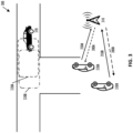
- FIG. 3 shows a diagram 300 of an example base station 310 operating in a reactive sensing mode of operation in an example environment with two approaching objects, according to one embodiment.
- the diagram 300 is similar to the diagram 200 shown in FIG. 2 , but includes two approaching objects 330A-B.
- the base station 310 includes the radar transceiver system 100 shown in FIG. 1 , and the approaching object 330A-B are vehicles that include communication systems.
- the approaching objects 330A-B transmit information request signals 350A-B, respectively, to the base station 310 as they approach along the road.
- the information request signal 350A can include an indicator of the region of interest 320A and a reaction time for the approaching object 330A
- the information request signal 350B can include an indicator of the region of interest 320B and a reaction time for the approaching object 330B.
- the base station 310 can determine a priority order based on the reaction times for the approaching objects 330A-B.
- the second approaching object 330B can be moving faster than the first approaching object 330A and have a shorter reaction time, such that the base station 310 prioritizes radar sensing of the region of interest 320B for the second approaching object 330B over radar sensing of the region of interest 320A for the first approaching object 330A and prioritizes transmission of the information signal 380B to the second approaching object 330B over transmission of the information signal 380A to the first approaching object 330A.
- the base station 310 can then schedule radar sensing slots within a communication frame based on the priority order.
- the base station 310 can determine whether the regions of interest 320A-B are overlapping or substantially the same, and if so, aggregate a radar sensing priority for the regions of interest 320A-B and determine a transmission priority order for the information signals 380A-B based on the reaction times for the approaching objects 330A-B.
- the base station 310 can determine the regions of interest 320A-B are substantially the same and aggregate the radar sensing priority for the regions of interest 320A-B.
- the base station can then prioritize transmission of the information signal 380B to the second approaching object 330B over transmission of the information signal 380A to the first approaching object 330A.
- the threshold amount of overlap between the regions of interest 320A-B can be determined based on the sizes of the regions of interest 320A-B, the radar sensing regions of base station 310, the field of view of the radar sensing system in base station 310, and the like.
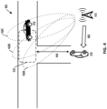
- FIG. 4 shows a diagram 400 of an example base station 410 operating in a proactive sensing mode of operation in an example environment, according to one embodiment.
- the base station 410 includes the radar transceiver system 100 shown in FIG. 1
- an approaching object 430 is a vehicle that includes a communication system.
- the regions of interest in the environment may be predetermined, and the base station 410 performs radar sensing of the region of interest 420 at intervals over time.
- the base station 410 can determine the location of the approaching object 430 relative to the region of interest 420 and transmit an information signal 480 including the most recent environmental information for the region of interest 420 to the approaching object 430 in response to the location of the approaching object 430 being within a particular threshold distance 440 from the region of interest 420.
- the threshold distance 440 can be chosen based on characteristics of the region of interest 420 and the approaching object 430, such as the expected speed of objects in the region of interest 420 and the expected speed and corresponding reaction time of the approaching object 430.
- the base station 410 performs radar sensing at intervals over time.
- the base station 410 can perform radar sensing at regular intervals over time, such as once every minute.
- the base station 410 can perform radar sensing during lulls in the communication demands of the base station 410. That is, the base station 410 can perform radar sensing in response to the communication bandwidth for the base station 410 being less than a threshold bandwidth.
- the base station 410 can perform radar sensing during lulls in the communication demands but not less frequently than once every minute.
- the base station 410 can perform radar sensing during lulls in the communication demands of base station 410, but ensures that radar sensing is performed at least once every minute regardless of the communication demands of base station 410.
- the base station 410 can further refine the scheduling of radar sensing based on characteristics of objects in the region of interest 420 such as expected speed and the like. Scheduling the radar sensing time slots within a communication frame is described further herein with respect to FIG. 5 .
- the base station 210 can operate in a high velocity sensing mode to use radar sensing data to determine the velocity of fast moving objects 270 in the environment.
- the radar sensing slots 560 can be interspersed at regular intervals among the set 564 of downlink communication slots and the set 568 of uplink communication slots.
- the number of radar sensing slots 560 and the intervals at which the radar sensing slots 560 are interspersed with the set 564 of downlink communication slots and the set 568 of uplink communication slots can be chosen based on an expected speed of fast moving objects 270 in the environment.
- the base station 210 can be positioned along a highway, and the posted speed limit of the highway can be used as the expected speed of fast moving objects 270 and to determine the appropriate number and interleaving of radar sensing slots 560 within the base station signal frame 550.
- the base station 210 can be positioned along a highway, and the oncoming lanes of the highway occupy a particular range of the field of view of the radar system included in the base station 210.
- the particular range of the field of view of the radar system can be used to determine the appropriate number of radar sensing slots 580 in the base station signal frame 570.
- the process 700 begins at step 710, at which a base station can optionally perform radar sensing of a region of interest at intervals over time to obtain environmental information.
- a base station can optionally perform radar sensing of a region of interest at intervals over time to obtain environmental information.
- the base station can perform radar sensing at regular intervals over time, such as once every minute, or during lulls in the communication demands of the base station.
- the base station obtains an indication of an approaching object.
- the base station then performs radar sensing of a region of interest to obtain environmental information at step 640.
- the process 800 begins at step 810, at which a base station obtains an indication of a first approaching object and an indication of a second approaching object.
- the base station can receive first and second information request from the first and second approaching objects, respectively, determine first and second location of the first and second approaching objects, or a combination thereof.
- the base station then performs radar sensing of a first region of interest for the first approaching object to obtain first environmental information and a second region of interest for the second approaching object to obtain second environmental information at step 820.
- the base station transmits the environmental information for the first region of interest to a communication system of the first approaching object and the environmental information for the second region of interest to a communication of the second approaching object based on the priority order.
- the base station can transmit the environment information based on the transmission priority order determined at optional step 855.
- a method includes obtaining an indication of an approaching object, performing radar sensing of a region of interest to obtain environmental information, and transmitting the environmental information for the region of interest to a communication system of the approaching object.
- obtaining the indication of the approaching object includes receiving, from the communication system of the approaching object, a request for the environmental information for the region of interest.
- the request for the environmental information for the region of interest can include at least one of an indicator of the region of interest and a reaction time for the approaching object.
- obtaining the indication of the approaching object includes determining a location of the approaching object relative to the region of interest, and transmitting the environmental information is performed in response to the location of the approaching object being within a threshold distance of the region of interest.
- the method can further include performing radar sensing of the region of interest at intervals over time and in response to the location of the approaching object being within the threshold distance of the region of interest, transmitting a current set of environmental information.
Landscapes
- Engineering & Computer Science (AREA)
- Radar, Positioning & Navigation (AREA)
- Remote Sensing (AREA)
- Computer Networks & Wireless Communication (AREA)
- Physics & Mathematics (AREA)
- General Physics & Mathematics (AREA)
- Electromagnetism (AREA)
- Signal Processing (AREA)
- Radar Systems Or Details Thereof (AREA)
Abstract
Description
- Joint communication and sensing systems share a single hardware platform and balance available resources spent on communication signals and signal processing and radar signals and signal processing. Base stations may perform radar sensing to obtain information about the surrounding environment and communicate the information about the environment to nearby user devices.
- The present invention may be better understood, and its numerous objects, features, and advantages made apparent to those skilled in the art by referencing the accompanying drawings.
-
FIG. 1 shows, in block diagram form, an example radar transceiver system, according to one embodiment. -
FIG. 2 shows a diagram of an example base station operating in a reactive sensing mode of operation in an example environment, according to one embodiment. -
FIG. 3 shows a diagram of an example base station operating in a reactive sensing mode of operation in an example environment with two approaching objects, according to one embodiment. -
FIG. 4 shows a diagram of an example base station operating in a proactive sensing mode of operation in an example environment, according to one embodiment. -
FIG. 5 shows diagrams of signal frames for the example base station shown inFIG. 2 and an approaching object, according to some embodiments. -
FIG. 6 shows, in flow chart form, an example process for infrastructure-assisted sensing and signaling, according to one embodiment. -
FIG. 7 shows, in flow chart form, another example process for infrastructure-assisted sensing and signaling, according to one embodiment. -
FIG. 8 shows, in flow chart form, a further example process for infrastructure-assisted sensing and signaling, according to one embodiment. - The use of the same reference symbols in different drawings indicates identical items unless otherwise noted. The Figures are not necessarily drawn to scale.
- As discussed previously herein, base stations can perform radar sensing to obtain information about the surrounding environment. The techniques and methods described herein enable base stations to operate in a reactive or proactive mode of operation to provide relevant environmental information to nearby objects in a timely manner. In a reactive sensing mode of operation, the base station obtains an indication of an approaching object, such as by receiving an information request from the approaching object. The information request can include a region of interest for the approaching object, a reaction time for the approaching object, and the like. The base station performs radar sensing of the region of interest to obtain environmental information and transmits the environment information to a communication system of the approaching object, for example within the reaction time for the approaching object.
- In a proactive sensing mode of operation, the base station performs radar sensing of a known region of interest at intervals over time, such as once every minute or during low bandwidth requirements on the communication resources of the base station. The base station obtains an indication of an approaching object, such as by determining a location of the approaching object relative to the region of interest, and transmits the most current environmental information to a communication system of the approaching object.
-
FIG. 1 shows, in block diagram form, an exampleradar transceiver system 100, according to an embodiment.Radar system 100 can be included in a user device, for example a vehicle's driver assistance system, or in a communication base station. Theexample radar system 100 is a frequency-modulated continuous wave (FMCW) radar system, also referred to as a continuous-wave frequency-modulated (CWFM) radar, and capable of determining the distance or range, velocity, and angle of arrival of an object in the field of view ofradar system 100. Althoughradar system 100 is described herein as a linear chirp radar system, any appropriate radar system that generates at least one of range, Doppler, and angle of arrival information can be used, such as orthogonal frequency-domain multiplexing, polyphase sequencing, binary sequencing, Zadoff-Chu sequencing, and the like. - In this example,
radar system 100 includes a microcontroller and processor unit (MCPU) 110, a digital-to-analog converter (DAC) 120, aradar sensor circuit 130, afirst antenna array 145, asecond antenna array 150, an analog-to-digital converter (ADC) 170, andstorage 180. Theradar sensor circuit 130 is a radar transceiver circuit in this example, and includes both transmitter and receiver signal chains. The MCPU 110 comprises one or more MCPU cores, general purpose processing cores, field-programmable gate arrays, digital signal processors, application-specific integrated circuits, and the like, or any combination thereof. The term "MCPU" in the singular is used herein to refer to either a single or multiple of the MCPU cores, general purpose processing cores, field-programmable gate arrays, digital signal processors, application-specific integrated circuits, and the like, or any combination thereof comprised in theMCPU 110. - MCPU 110 includes a
radar controller 115 and asignal processor 175. Theradar controller 115 can receive data from theradar sensor circuit 130 and control radar parameters of theradar sensor circuit 130 such as frequency band, length of a radar frame, and the like via theDAC 120. A control signal fromDAC 120 can be used to adjust the radar sensing signals output from asensing signal generator 135 included in theradar sensor circuit 130. Thesignal processor 175 in MCPU 110 can also receive the data from theradar sensor circuit 130 and perform signal processing for determining a distance or range between a target object andradar system 100, a velocity of the target object, an angle of arrival for the target object, and the like. Thesignal processor 175 can provide the calculated values to thestorage 180 and/or to other systems via theinterface 190. - The
interface 190 can enable the MCPU 110 to communicate with other systems over local and wide area networks, the internet, automotive communication buses, and/or other kinds of wired or wireless communication systems, for example. The MCPU 110 can provide the calculated values over theinterface 190 to other systems and devices. For example, theradar system 100 is included in a communication base station and provides the calculated values of distance, velocity, and angle of arrival to user devices, such as vehicles in the proximity of the communication base station. As another example, theradar system 100 is included in a vehicle's driver assistance system and provides the calculated values of distance, velocity, and angle of arrival to the driver assistance systems of other nearby vehicles. Thestorage 180 can be used to store instructions for theMCPU 110, received data from theradar sensor circuit 130, calculated values from thesignal processor 175, and the like.Storage 180 can be any appropriate storage medium, such as a volatile or non-volatile memory. - The
radar sensor circuit 130 includes thesensing signal generator 135, atransmitter 140, areceiver 155, and abaseband processor 160. Thesensing signal generator 135 can include a local oscillator, for example, and generates radar sensing signals and provides them to thetransmitter 140. For example, thesensing signal generator 135 can frequency modulate a continuous wave signal to form a series of linear chirp signals. The transmitted chirp signal of a known, stable frequency continuous wave varies up and down in frequency over a fixed period of time by the modulated signal. Thesensing signal generator 135 provides the generated chirp signals to thetransmitter 140, which drives thefirst antenna array 145 of one or more transmitter (TX) antennas. Thesecond antenna array 150 comprises one or more receiver (RX) antennas and receives signals reflected from objects in the path of the transmitted chirp signals from theTX antenna array 145. The TXantenna array 145 and theRX antenna array 150 can be stationary or configured to transmit and receive across a range of area, such as by mechanical movement. - The
receiver 155 receives the reflected signals from theRX antenna array 150 and provides them to thebaseband processor 160. Thebaseband processor 160 also receives the transmitted sensing signals from thesensing signal generator 135 and down-converts the received sensing signals directly into the baseband using the copy of the transmitted sensing signals from thesensing signal generator 135. Thebaseband processor 160 can then filter and amplify the baseband signal. Thebaseband processor 160 provides the filtered and amplified baseband signal to theADC 170, which digitizes the signal and provides it to theMCPU 110. Thesignal processor 175 in theMCPU 110 can then perform time domain to frequency domain transforms such as fast Fourier transforms (FFTs) and other signal processing to determine the distance, velocity, and angle of arrival between the target object and theradar system 100. - Frequency differences between the received reflections and the transmitted sensing signal increase with delay and so are proportional to distance. The phase differences between the received reflections across consecutive chirps in a radar frame are indicative of the velocity of objects in the field of view. For implementations in which
RX antenna array 150 includes two or more receiver antennas, the phase difference between received reflections at a first RX antenna and received reflections at a second RX antenna can be used to determine the angle of arrival of target objects. For example, the down-converted and digitized receive signal corresponding to each chirp is first transformed using an FFT (called the range FFT). The range FFT produces a series of range bins with the value of each range bin denoting the signal strength of reflected targets at the corresponding range. A Doppler FFT is then performed for each range bin across all the chirps in a frame to estimate the velocities of reflected targets. Additional processing can then be performed to determine the angle of arrival between the targets and theradar system 100. - For an implementation in which the
radar transceiver system 100 is included in a joint communication and sensing base station, the base station can use the determined distance, velocity, and angle of arrival for objects in the field of view from theradar system 100 to provide information about objects in the environment to other devices in the proximity of the communication base station. For example, the communication base station can provide environmental information to vehicles moving through the field of view of theradar system 100. The communication base station can incorporate radar sensing slots into the communication frame between the communication base station and a nearby vehicle, such that the base station is able to provide meaningful environmental information without disrupting normal communications between the base station and the nearby vehicle. -
FIG. 2 shows a diagram 200 of anexample base station 210 operating in a reactive sensing mode of operation in an example environment, according to one embodiment. In this example, thebase station 210 includes theradar transceiver system 100 shown inFIG. 1 , and an approachingobject 230 is a vehicle that includes a communication system. The approachingobject 230 transmits aninformation request signal 250 to thebase station 210 as it approaches along the road. Theinformation request signal 250 can include an indicator of a region of interest to the approachingobject 230, such as the intersection included in the region ofinterest 220, a reaction time for the approachingobject 230, or both. The reaction time for the approachingobject 230 can indicate an amount of time before the approachingobject 230 reaches the region ofinterest 220 and thus, an amount of time in which thebase station 210 can perform radar sensing of the region ofinterest 220 and provide the environmental information about the region ofinterest 220 to the approachingobject 230. - For example, the approaching
object 230 transmits theinformation request signal 250 in response to being afirst distance 240 away from the region ofinterest 220. The approachingobject 230 is moving at a particular speed and must receive the environmental information from thebase station 210 before the approachingobject 230 is a second distance 245 away from the region of interest. The reaction time can indicate the amount of time for the approachingobject 230 to travel from thefirst distance 240 to the second distance 245 and thus, the amount of time for thebase station 210 to provide environmental information about the region ofinterest 220 to the approachingobject 230. Thefirst distance 240 and the second distance 245 can be chosen based on the environment and the speed at which the approachingobject 230 moves. Thefirst distance 240 and the second distance 245 are given by way of example to illustrate possible triggers for sending theinformation request signal 250 and determining the reaction time; any appropriate technique to determine an appropriate time at which to send theinformation request signal 250 and/or to determine a reaction time for the approachingobject 230 can be used. - In response to receiving the
information request signal 250, thebase station 210 can perform radar sensing of the region ofinterest 220 to obtain environmental information, such as objects detected in the region ofinterest 220 and corresponding velocities and angles of arrival for the detected objects. That is, in a reactive sensing mode of operation, thebase station 210 performs radar sensing in response to receiving aninformation request signal 250. In this example, the region ofinterest 220 includes a portion of avehicle 270, and the environmental information can include location information for thevehicle 270, a velocity of thevehicle 270, and an angle of arrival for thevehicle 270. Thebase station 210 can then transmit aninformation signal 280 with the environmental information to the approachingobject 230. - The
base station 210 can perform radar sensing in stages based on the field of view of theradar transceiver system 100 included in thebase station 120 and the size of the region ofinterest 220. That is, thebase station 210 can perform a first radar sensing operation over a region indicated by 260A, a second radar sensing operation over a region indicated by 260B, and a third radar sensing operation over a region indicated by 260C and aggregate the radar data to obtain environmental information for the region ofinterest 220. - In addition, the
base station 210 can schedule the radar sensing operations into radar sensing time slots within communication frames for thebase station 210 based on the reaction time included in theinformation request 250 and the region ofinterest 220. For example, thebase station 210 can schedule at least one sensing time slot within a communication frame such that the radar sensing operations and resulting radar calculations are completed in time to transmit the environmental information to the approachingobject 230 within the time limits indicated by the reaction time. As another example, vehicles traveling through the region ofinterest 220 are expected to be traveling at a particular speed, such as a speed indicated by a speed limit. Thebase station 210 can schedule an appropriate number of sensing time slots at appropriate intervals within the communication frame such that the velocity of fast-moving vehicles traveling through the region ofinterest 220 can be determined. Scheduling the radar sensing time slots within a communication frame is described further herein with respect toFIG. 5 . -
FIG. 3 shows a diagram 300 of anexample base station 310 operating in a reactive sensing mode of operation in an example environment with two approaching objects, according to one embodiment. The diagram 300 is similar to the diagram 200 shown inFIG. 2 , but includes two approachingobjects 330A-B. For ease of illustration, the radar sensing regions indicated as 260A-C in diagram 200 are omitted from diagram 300. Thebase station 310 includes theradar transceiver system 100 shown inFIG. 1 , and the approachingobject 330A-B are vehicles that include communication systems. The approaching objects 330A-B transmit information request signals 350A-B, respectively, to thebase station 310 as they approach along the road. Theinformation request signal 350A can include an indicator of the region ofinterest 320A and a reaction time for the approachingobject 330A, and theinformation request signal 350B can include an indicator of the region ofinterest 320B and a reaction time for the approachingobject 330B. - In response to receiving the information request signals 350A-B, the
base station 310 can determine a priority order based on the reaction times for the approachingobjects 330A-B. For example, the second approachingobject 330B can be moving faster than the first approachingobject 330A and have a shorter reaction time, such that thebase station 310 prioritizes radar sensing of the region ofinterest 320B for the second approachingobject 330B over radar sensing of the region ofinterest 320A for the first approachingobject 330A and prioritizes transmission of the information signal 380B to the second approachingobject 330B over transmission of the information signal 380A to the first approachingobject 330A. Thebase station 310 can then schedule radar sensing slots within a communication frame based on the priority order. - In some implementations, the
base station 310 can determine whether the regions ofinterest 320A-B are overlapping or substantially the same, and if so, aggregate a radar sensing priority for the regions ofinterest 320A-B and determine a transmission priority order for the information signals 380A-B based on the reaction times for the approachingobjects 330A-B. Returning to the example in which the second approachingobject 330B moves faster than the first approachingobject 330A and has a shorter reaction time, thebase station 310 can determine the regions ofinterest 320A-B are substantially the same and aggregate the radar sensing priority for the regions ofinterest 320A-B. The base station can then prioritize transmission of the information signal 380B to the second approachingobject 330B over transmission of the information signal 380A to the first approachingobject 330A. The threshold amount of overlap between the regions ofinterest 320A-B can be determined based on the sizes of the regions ofinterest 320A-B, the radar sensing regions ofbase station 310, the field of view of the radar sensing system inbase station 310, and the like. -
FIG. 4 shows a diagram 400 of anexample base station 410 operating in a proactive sensing mode of operation in an example environment, according to one embodiment. In this example, thebase station 410 includes theradar transceiver system 100 shown inFIG. 1 , and an approachingobject 430 is a vehicle that includes a communication system. In the proactive sensing mode of operation, the regions of interest in the environment may be predetermined, and thebase station 410 performs radar sensing of the region ofinterest 420 at intervals over time. Thebase station 410 can determine the location of the approachingobject 430 relative to the region ofinterest 420 and transmit aninformation signal 480 including the most recent environmental information for the region ofinterest 420 to the approachingobject 430 in response to the location of the approachingobject 430 being within aparticular threshold distance 440 from the region ofinterest 420. Thethreshold distance 440 can be chosen based on characteristics of the region ofinterest 420 and the approachingobject 430, such as the expected speed of objects in the region ofinterest 420 and the expected speed and corresponding reaction time of the approachingobject 430. - In the proactive sensing mode of operation, the
base station 410 performs radar sensing at intervals over time. For example, thebase station 410 can perform radar sensing at regular intervals over time, such as once every minute. As another example, thebase station 410 can perform radar sensing during lulls in the communication demands of thebase station 410. That is, thebase station 410 can perform radar sensing in response to the communication bandwidth for thebase station 410 being less than a threshold bandwidth. As a further example, thebase station 410 can perform radar sensing during lulls in the communication demands but not less frequently than once every minute. That is, thebase station 410 can perform radar sensing during lulls in the communication demands ofbase station 410, but ensures that radar sensing is performed at least once every minute regardless of the communication demands ofbase station 410. Thebase station 410 can further refine the scheduling of radar sensing based on characteristics of objects in the region ofinterest 420 such as expected speed and the like. Scheduling the radar sensing time slots within a communication frame is described further herein with respect toFIG. 5 . -
FIG. 5 shows diagrams of signal frames for thebase station 210 shown inFIG. 2 , according to some embodiments. For ease of illustration,FIG. 5 is described herein with reference to the diagram 200 shown inFIG. 2 , but the signal frames shown inFIG. 5 are also applicable to the diagram 300 shown inFIG. 3 and the diagram 400 shown inFIG. 4 . The diagram 500 includes base station signal frames 510, 550, and 570. The basestation signal frame 510 includes a set 520 of radar sensing slots, aset 524 of downlink communication slots, and aset 528 of uplink communication slots. The set 520 of radar sensing slots are interspersed among slots in theset 524 of downlink communication slots and theset 528 of uplink communication slots. - The base
station signal frame 510 includes the set 524 of downlink communication slots during which thebase station 210 transmits information to one or more communication systems of the approachingobject 230 or other nearby objects. During theset 528 of uplink communication slots in the basestation signal frame 510, thebase station 210 receives information from one or more communication systems of the approachingobject 230 or other nearby objects. The radar sensing slots 520 in the basestation signal frame 510 are interspersed among theset 524 of the downlink communication slots and theset 528 of the uplink communication slots. The numbers of downlink communication slots in theset 524, uplink communication slots in theset 528, and radar sensing slots 520 in the basestation signal frame 510 are by way of example only, and can vary based on the particular communication standard implemented. In addition, the location of the radar sensing slots 520 within the basestation signal frame 510 can vary based on the desired accuracy and other characteristics of the radar sensing. - For example as shown in base
station signal frame 550, thebase station 210 can operate in a high velocity sensing mode to use radar sensing data to determine the velocity of fast movingobjects 270 in the environment. In the high velocity sensing mode, the radar sensing slots 560 can be interspersed at regular intervals among theset 564 of downlink communication slots and theset 568 of uplink communication slots. The number of radar sensing slots 560 and the intervals at which the radar sensing slots 560 are interspersed with theset 564 of downlink communication slots and theset 568 of uplink communication slots can be chosen based on an expected speed of fast movingobjects 270 in the environment. For example, thebase station 210 can be positioned along a highway, and the posted speed limit of the highway can be used as the expected speed of fast movingobjects 270 and to determine the appropriate number and interleaving of radar sensing slots 560 within the basestation signal frame 550. - As another example shown in base
station signal frame 570, thebase station 210 can operate in a high angular resolution mode to use radar sensing data to determine the angle of arrival ofobjects 270 in the environment with a higher accuracy than in other operating modes. In the high angular resolution mode, theradar sensing slots 580 can be grouped together in a single block between the set 584 of downlink communication slots and theset 588 of uplink communication slots. The number ofradar sensing slots 580 to be grouped together in the basestation signal frame 570 can be chosen based on an expected range of angles of arrival ofobjects 270 in the environment. For example, thebase station 210 can be positioned along a highway, and the oncoming lanes of the highway occupy a particular range of the field of view of the radar system included in thebase station 210. The particular range of the field of view of the radar system can be used to determine the appropriate number ofradar sensing slots 580 in the basestation signal frame 570. - In addition, the base station can change the mode of operation, such that the communication signal frame format changes. For example, at a first time the
base station 210 can operate in a normal mode of operation and use the basestation signal frame 510 to perform radar sensing and communicate with the approachingobject 230. At a second, later time, thebase station 210 can change to either of the high velocity sensing mode and the high angular resolution mode and use the corresponding basestation signal frame -
FIG. 6 shows, in flow chart form, anexample process 600 for infrastructure-assisted sensing and signaling, according to one embodiment. For ease of illustration, theprocess 600 is described herein with reference to the diagrams 200 and 400 shown inFIGS. 2 and4 , respectively. Theprocess 600 can be performed by any appropriate processing unit executing instructions stored in any appropriate non-transitory computer-readable medium. The steps ofprocess 600 are shown in a particular order inFIG. 6 , but the steps ofprocess 600 may be performed in a different order and/or with some steps performed simultaneously. One or more steps ofprocess 600 can be optional, andprocess 600 can include additional steps. - The
process 600 begins atstep 610, at which a base station obtains an indication of an approaching object. In a reactive sensing mode of operation as described herein with reference toFIG. 2 , the base station can receive a request for environmental information for the region of interest from the approaching object atstep 620. In a proactive sensing mode of operation as described herein with reference toFIG. 4 , the base station can determine a location of the approaching object relative to the region of interest atstep 630. The base station can then perform radar sensing of a region of interest to obtain environmental information atstep 640. - In the proactive sensing mode of operation, the base station can determine whether the location of the approaching object is within a threshold distance of the region of interest at
step 650. For example as described herein with respect toFIG. 4 , the base station determines whether the approachingobject 430 is within thethreshold distance 440 of the region ofinterest 420. The threshold distance can be chosen based on characteristics of the region of interest and the approaching object, such as the expected speed of objects in the region of interest and the expected speed and corresponding reaction time of the approaching object. In response to determining the approaching object is within the threshold distance atstep 650 or after performing the radar sensing atstep 640, the base station can transmit the environmental information for the region of interest to a communication system of the approaching object atstep 660. -
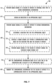
FIG. 7 shows, in flow chart form, anotherexample process 700 for infrastructure-assisted sensing and signaling, according to one embodiment. For ease of illustration, theprocess 700 is described herein with reference to the diagrams 200 and 400 shown inFIGS. 2 and4 , respectively, and theprocess 600 shown inFIG. 6 . Theprocess 700 can be performed by any appropriate processing unit executing instructions stored in any appropriate non-transitory computer-readable medium. The steps ofprocess 700 are shown in a particular order inFIG. 7 , but the steps ofprocess 700 may be performed in a different order and/or with some steps performed simultaneously. One or more steps ofprocess 700 can be optional, andprocess 700 can include additional steps. - The
process 700 begins atstep 710, at which a base station can optionally perform radar sensing of a region of interest at intervals over time to obtain environmental information. For example as described herein with respect toFIG. 4 , the base station can perform radar sensing at regular intervals over time, such as once every minute, or during lulls in the communication demands of the base station. Atstep 610, the base station obtains an indication of an approaching object. The base station then performs radar sensing of a region of interest to obtain environmental information atstep 640. - Performing radar sensing at
step 640 can optionally includesteps step 720, the base station determines a reaction time for the approaching object, for example based on a velocity of the approaching object. Atstep 730, the base station schedules one or more radar sensing slots within one or more communication frames based on the reaction time determined atstep 720 and characteristics of the region of interest, such as an expected speed of objects in the region of interest. For example, the base station can schedule the radar sensing slots such that the location, velocity, and angle of arrival of objects in the region of interest can be determined and provided to the approaching object within the appropriate reaction time. Atstep 740, the base station performs radar sensing of the region of interest during the one or more scheduled radar sensing slots. - At
optional step 750, the base station can map the environmental information based on at least one of an orientation and velocity of the approaching object. For example, the base station can adapt the environmental information such that the approaching object can display a representation of the environmental information as a map. As another example, the base station can adapt the environmental information such that the location, velocity, and angle of arrival of objects in the region are given relative to the location and velocity of the approaching object. Atstep 660, the base station transmits the environmental information for the region of interest to a communication system of the approaching object. -
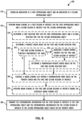
FIG. 8 shows, in flow chart form, afurther example process 800 for infrastructure-assisted sensing and signaling, according to one embodiment. For ease of illustration, theprocess 800 is described herein with reference to the diagrams 200 and 400 shown inFIGS. 2 and4 , respectively. Theprocess 800 can be performed by any appropriate processing unit executing instructions stored in any appropriate non-transitory computer-readable medium. The steps ofprocess 800 are shown in a particular order inFIG. 8 , but the steps ofprocess 800 may be performed in a different order and/or with some steps performed simultaneously. One or more steps ofprocess 800 can be optional, andprocess 800 can include additional steps. - The
process 800 begins atstep 810, at which a base station obtains an indication of a first approaching object and an indication of a second approaching object. The base station can receive first and second information request from the first and second approaching objects, respectively, determine first and second location of the first and second approaching objects, or a combination thereof. The base station then performs radar sensing of a first region of interest for the first approaching object to obtain first environmental information and a second region of interest for the second approaching object to obtain second environmental information atstep 820. - Performing radar sensing at
step 820 can optionally includesteps step 830, the base station determines a first reaction time for the first approaching object and a second reaction time for the second approaching object. Atstep 840, the base station determines a priority order based on the first and second reaction times. For example, the base station can prioritize radar sensing of the first region of interest for the first approaching object in response to the first reaction time being shorter than the second reaction time. - Determining the priority order at
step 840 can optionally includesteps step 845, the base station determines whether the first and second regions of interest are substantially the same or have a threshold amount of overlap. For example as described herein with respect toFIG. 3 , the threshold amount of overlap between the regions of interest can be determined based on the sizes of the regions of interest, radar sensing regions of the base station, the field of view of the radar sensing system in the base station, and the like. In response to the first and second regions of interest being substantially the same atstep 845, the base station proceeds to step 850 and aggregates a radar sensing priority for the first and second regions of interest such that the first and second regions of interest are given a same priority. Atstep 855, the base station determines a transmission priority order for the first and second environmental information based on the first and second reaction times. For example, the base station can prioritize transmission of the environmental information for the region of interest corresponding to the approaching object with a shorter reaction time. - The base station proceeds to step 860 in response to the first and second regions of interest not being substantially the same at
step 845 and fromstep 855, at which the base station schedules at least one radar sensing slot within at least one communication frame based on the priority order and characteristics of the first and second regions of interest, such as an expected speed of objects in the region of interest. For example, the base station can schedule the radar sensing slots such that the first region of interest is sensed first in response to the priority order indicating that the first region of interest has a higher priority than the second region of interest. Atstep 870, the base station performs radar sensing of the first and second regions of interest during the one or more scheduled radar sensing slots. - At
step 880, the base station transmits the environmental information for the first region of interest to a communication system of the first approaching object and the environmental information for the second region of interest to a communication of the second approaching object based on the priority order. For example, the base station can transmit the environment information based on the transmission priority order determined atoptional step 855. - As discussed previously herein, the disclosed techniques and methods enable base stations to operate in a reactive or proactive mode of operation to provide relevant environmental information to nearby objects in a timely manner. In a reactive sensing mode of operation, the base station obtains an indication of an approaching object by receiving an information request from the approaching object. The information request can include a region of interest for the approaching object, a reaction time for the approaching object, and the like. The base station performs radar sensing of the region of interest to obtain environmental information and transmits the environment information to a communication system of the approaching object, for example within the reaction time for the approaching object. In a proactive sensing mode of operation, the base station performs radar sensing of a known region of interest at intervals over time, such as once every minute. The base station obtains an indication of an approaching object by determining a location of the approaching object relative to the region of interest, and transmits the most current environmental information to a communication system of the approaching object.
- Features specifically shown or described with respect to one embodiment set forth herein may be implemented in other embodiments set forth herein.
- In this description, the term "couple" may cover connections, communications, or signal paths that enable a functional relationship consistent with this description, including intermediate or intervening components that do not alter the functional relationship. A device that is "configured to" perform a task or function may be configured by programming or hardwiring, for example, at a time of manufacturing by a manufacturer and/or may be configurable or reconfigurable by a user after manufacturing. The configuring may be done through firmware and/or software, construction and/or layout of hardware components and connections, or any combination thereof. As used herein, "node", "pin", and "lead" are used interchangeably. A circuit or device described herein as including certain components may be adapted to be coupled to those components instead, to form the described circuitry or device.
- While particular embodiments of the present invention have been shown and described, it will be recognized to those skilled in the art that, based upon the teachings herein, further changes and modifications may be made without departing from this invention and its broader aspects, and thus, the appended claims are to encompass within their scope all such changes and modifications as are within the scope of this invention.
- A radar system includes at least one transmitter, at least one receiver, at least one processor, and at least one non-transitory computer-readable medium storing machine instructions. The machine instructions cause the at least one processor to obtain an indication of an approaching object, perform radar sensing of a region of interest to obtain environmental information, and transmit the environmental information for the region of interest to a communication system of the approaching object. In some implementations, the machine instructions to obtain the indication of the approaching object includes instructions to receive, from the communication system of the approaching object, a request for the environmental information for the region of interest. The request for environmental information for the region of interest can include at least one of an indicator of the region of interest and a reaction time for the approaching object in some embodiments.
- In some implementations, the machine instructions to obtain the indication of the approaching object include instructions to determine a location of the approaching object relative to the region of interest, and the radar system is configured to transmit the environmental information in response to the location of the approaching object being within a threshold distance of the region of interest. The radar system can be further configured to perform radar sensing of the region of interest at intervals over time and in response to the location of the approaching object being within the threshold distance of the region of interest, transmit a current set of environmental information.
- In some implementations, the environmental information for the region of interest includes at least one of a location of an identified object in the region of interest, a velocity of the identified object, and an angle of arrival for the identified object. The non-transitory computer-readable medium can further store machine instructions to cause the at least one processor to map the at least one of the location, velocity, and angle of arrival for the identified object based on at least one of an orientation and a velocity of the approaching object.
- In some implementations, the machine instructions to perform radar sensing of the region of interest include machine instructions to determine a reaction time for the approaching object, schedule at least one sensing slot within at least one communication frame based on the determined reaction time and the region of interest, and perform the radar sensing of the region of interest during the at least one sensing slot within the at least one communication frame. In some implementations, the machine instructions to schedule the at least one sensing slot within the at least one communication frame include machine instructions to determine an expected speed for identified objects in the region of interest, determine a number of sensing slots and a number of communication frames such that an identified object moving at the expected speed can be detected, and schedule the number of sensing slots within the number of communication frames based on the determined reaction time, the region of interest, and the expected speed, such that the identified object moving at the expected speed can be detected.
- In some implementations, the approaching object is a first approaching object and the region of interest is a first region of interest for the first approaching object. The non-transitory computer-readable medium further stores machine instructions to cause the at least one processor to obtain an indication of a second approaching object, determine a first reaction time for the first approaching object and a second reaction time for the second approaching object, determine a priority order based on the first and second reaction times, schedule at least one sensing slot within at least one communication frame based on the determined priority order and the first region of interest for the first approaching object and a second region of interest for the second approaching object, perform the radar sensing of the first and second regions of interest during the at least one sensing slot within the at least one communication frame, and transmit the environmental information for the first region of interest to a communication system of the first approaching object and environmental information for the second region of interest to a communication system of the second approaching object based on the determined priority order.
- In some implementations, the machine instructions to determine the priority order based on the first and second reaction times include machine instructions to determine whether the first region of interest for the first approaching object and the second region of interest for the second approaching object are substantially the same and determine whether the first region of interest for the first approaching object and the second region of interest for the second approaching object are substantially the same. In response to the first and second regions of interest being substantially the same, the machine instructions cause the at least one processor to aggregate a radar sensing priority for the first and second regions of interest, and determine a transmission priority order based on the first and second reaction times. The environmental information for the first region of interest and the environmental information for the second region of interest can be transmitted based on the determined transmission priority order.
- A method includes obtaining an indication of an approaching object, performing radar sensing of a region of interest to obtain environmental information, and transmitting the environmental information for the region of interest to a communication system of the approaching object. In some implementations, obtaining the indication of the approaching object includes receiving, from the communication system of the approaching object, a request for the environmental information for the region of interest. The request for the environmental information for the region of interest can include at least one of an indicator of the region of interest and a reaction time for the approaching object.
- In some implementations, obtaining the indication of the approaching object includes determining a location of the approaching object relative to the region of interest, and transmitting the environmental information is performed in response to the location of the approaching object being within a threshold distance of the region of interest. In some embodiments, the method can further include performing radar sensing of the region of interest at intervals over time and in response to the location of the approaching object being within the threshold distance of the region of interest, transmitting a current set of environmental information. In some implementations, the environmental information for the region of interest includes at least one of a location of an identified object in the region of interest, a velocity of the identified object, and an angle of arrival for the identified object, and the method further includes mapping at least one of the location, velocity, and angle of arrival for the identified object based on at least one of an orientation and a velocity of the approaching object.
- A non-transitory computer-readable medium stores machine instructions which, when executed by at least one processor, cause the at least one processor to obtain an indication of an approaching object, perform radar sensing of a region of interest to obtain environmental information, and transmit the environmental information for the region of interest to a communication system of the approaching object. In some implementations, the machine instructions to obtain the indication of the approaching object includes instructions to receive, from the communication system of the approaching object, a request for the environmental information for the region of interest. The request for environmental information for the region of interest can include at least one of an indicator of the region of interest and a reaction time for the approaching object in some embodiments.
- In some implementations, the machine instructions to obtain the indication of the approaching object include instructions to determine a location of the approaching object relative to the region of interest, and the non-transitory computer-readable medium further stores machine instructions which, when executed by the at least one processor, cause the at least one processor to perform radar sensing of the region of interest at intervals over time and in response to the location of the approaching object being within a threshold distance of the region of interest, transmit a current set of environmental information. In some implementations, the environmental information for the region of interest includes at least one of a location of an identified object in the region of interest, a velocity of the identified object, and an angle of arrival for the identified object. The non-transitory computer-readable medium stores machine instructions which, when executed by the at least one processor, further cause the at least one processor to map at least one of the location, velocity, and angle of arrival for the identified object based on at least one of an orientation and a velocity of the approaching object.
Claims (15)
- A radar system, comprising:at least one transmitter;at least one receiver;at least one processor; andat least one non-transitory computer-readable medium storing machine instructions which, when executed by the at least one processor, cause the at least one processor to:obtain an indication of an approaching object;perform radar sensing of a region of interest to obtain environmental information; andtransmit the environmental information for the region of interest to a communication system of the approaching object.
- The radar system of claim 1, wherein the machine instructions to obtain the indication of the approaching object include instructions to receive, from the communication system of the approaching object, a request for the environmental information for the region of interest.
- The radar system of claim 2, wherein the request for the environmental information for the region of interest includes at least one of an indicator of the region of interest and a reaction time for the approaching object.
- The radar system of any of claims 1 to 3, wherein the machine instructions to obtain the indication of the approaching object include instructions to determine a location of the approaching object relative to the region of interest, and wherein the radar system is configured to transmit the environmental information in response to the location of the approaching object being within a threshold distance of the region of interest.
- The radar system of claim 4, wherein the radar system is configured to:perform radar sensing of the region of interest at intervals over time; andin response to the location of the approaching object being within the threshold distance of the region of interest, transmit a current set of environmental information.
- The radar system of any of claims 1 to 5, wherein the environmental information for the region of interest includes at least one of a location of an identified object in the region of interest, a velocity of the identified object, and an angle of arrival for the identified object.
- The radar system of claim 6, wherein the non-transitory computer-readable medium stores machine instructions which, when executed by the at least one processor, further cause the at least one processor to map at least one of the location, velocity, and angle of arrival for the identified object based on at least one of an orientation and a velocity of the approaching object.
- The radar system of any of claims 1 to 7, wherein the machine instructions to perform radar sensing of the region of interest further comprise machine instructions to:determine a reaction time for the approaching object;schedule at least one sensing slot within at least one communication frame based on the determined reaction time and the region of interest; andperform the radar sensing of the region of interest during the at least one sensing slot within the at least one communication frame.
- The radar system of claim 8, wherein the machine instructions to schedule at least one sensing slot within at least one communication frame further comprise machine instructions to:determine an expected speed for identified objects in the region of interest;determine a number of sensing slots and a number of communication frames such that an identified object moving at the expected speed can be detected; andschedule the number of sensing slots within the number of communication frames based on the determined reaction time, the region of interest, and the expected speed, such that the identified object moving at the expected speed can be detected.
- The radar system of any of claims 1 to 9, wherein the approaching object is a first approaching object and the region of interest is a first region of interest for the first approaching object, and wherein the non-transitory computer-readable medium stores machine instructions which, when executed by the at least one processor, further cause the at least one processor to:obtain an indication of a second approaching object;determine a first reaction time for the first approaching object and a second reaction time for the second approaching object;determine a priority order based on the first and second reaction times;schedule at least one sensing slot within at least one communication frame based on the determined priority order and the first region of interest for the first approaching object and a second region of interest for the second approaching object;perform the radar sensing of the first and second regions of interest during the at least one sensing slot within the at least one communication frame; andtransmit the environmental information for the first region of interest to a communication system of the first approaching object and environmental information for the second region of interest to a communication system of the second approaching object based on the determined priority order.
- The radar system of claim 10, wherein the machine instructions to determine a priority order based on the first and second reaction times further comprise machine instructions to:determine whether the first region of interest for the first approaching object and the second region of interest for the second approaching object are substantially the same;in response to the first and second regions of interest being substantially the same:aggregate a radar sensing priority for the first and second regions of interest; anddetermine a transmission priority order based on the first and second reaction times, wherein the environmental information for the first region of interest and the environmental information for the second region of interest are transmitted based on the determined transmission priority order.
- A method, comprising:obtaining an indication of an approaching object;performing radar sensing of a region of interest to obtain environmental information; andtransmitting the environmental information for the region of interest to a communication system of the approaching object.
- The method of claim 12, wherein obtaining the indication of the approaching object includes receiving, from the communication system of the approaching object, a request for the environmental information for the region of interest, wherein the request for the environmental information for the region of interest includes at least one of an indicator of the region of interest and a reaction time for the approaching object.
- The method of any of claims 12 to 13, wherein obtaining the indication of the approaching object includes determining a location of the approaching object relative to the region of interest, wherein transmitting the environmental information is performed in response to the location of the approaching object being within a threshold distance of the region of interest.
- The method of claim 14, further comprising:performing radar sensing of the region of interest at intervals over time; andin response to the location of the approaching object being within the threshold distance of the region of interest, transmitting a current set of environmental information.
Applications Claiming Priority (1)
| Application Number | Priority Date | Filing Date | Title |
|---|---|---|---|
| US18/148,498 US12613305B2 (en) | 2022-12-30 | 2022-12-30 | Infrastructure-assisted signalling and sensing systems |
Publications (2)
| Publication Number | Publication Date |
|---|---|
| EP4394431A1 true EP4394431A1 (en) | 2024-07-03 |
| EP4394431B1 EP4394431B1 (en) | 2025-07-23 |
Family
ID=89190849
Family Applications (1)
| Application Number | Title | Priority Date | Filing Date |
|---|---|---|---|
| EP23215730.5A Active EP4394431B1 (en) | 2022-12-30 | 2023-12-12 | Infrastructure-assisted signalling and sensing systems |
Country Status (2)
| Country | Link |
|---|---|
| US (1) | US12613305B2 (en) |
| EP (1) | EP4394431B1 (en) |
Citations (2)
| Publication number | Priority date | Publication date | Assignee | Title |
|---|---|---|---|---|
| US20220065982A1 (en) * | 2018-10-18 | 2022-03-03 | Saab Ab | Traffic management system and an unmanned aerial vehicle compatible with such a system |
| WO2022081624A1 (en) * | 2020-10-16 | 2022-04-21 | Qualcomm Incorporated | Radio frequency sensing communication |
Family Cites Families (36)
| Publication number | Priority date | Publication date | Assignee | Title |
|---|---|---|---|---|
| US4016564A (en) * | 1975-04-14 | 1977-04-05 | Rca Corporation | Multiple target data receiver for a collision avoidance system |
| US4040054A (en) * | 1975-08-27 | 1977-08-02 | Westinghouse Electric Corporation | Tracking of radar signals |
| US4454510A (en) * | 1978-12-18 | 1984-06-12 | Crow Robert P | Discrete address beacon, navigation and landing system (DABNLS) |
| US5841367A (en) * | 1990-11-07 | 1998-11-24 | Giovanni; Caico | Electronic equipment for prevention of collisions between vehicles |
| US8965677B2 (en) * | 1998-10-22 | 2015-02-24 | Intelligent Technologies International, Inc. | Intra-vehicle information conveyance system and method |
| ATE468577T1 (en) * | 1998-11-23 | 2010-06-15 | Integrated Transp Information | IMMEDIATE TRAFFIC MONITORING SYSTEM |
| US6798374B1 (en) * | 2002-11-05 | 2004-09-28 | Decatur Electronics Inc. | Traffic surveillance radar using ranging for accurate target identification |
| US20060262007A1 (en) * | 2004-01-16 | 2006-11-23 | Clariant Technologies, Corp. | Methods and apparatus for automotive radar sensors |
| US7032858B2 (en) * | 2004-08-17 | 2006-04-25 | Raytheon Company | Systems and methods for identifying targets among non-targets with a plurality of sensor vehicles |
| WO2011095974A1 (en) * | 2010-02-03 | 2011-08-11 | Liron Elia | Methods and systems of collision avoidance and/or alerting for users of mobile communication devices |
| EP2390744B1 (en) * | 2010-05-31 | 2012-11-14 | Volvo Car Corporation | Control system for travel in a platoon |
| JP5825100B2 (en) * | 2011-05-31 | 2015-12-02 | 富士通株式会社 | Sensor data collection system |
| US8441394B2 (en) * | 2011-07-11 | 2013-05-14 | Delphi Technologies, Inc. | System and method for detecting obstructions and misalignment of ground vehicle radar systems |
| US9000903B2 (en) * | 2012-07-09 | 2015-04-07 | Elwha Llc | Systems and methods for vehicle monitoring |
| US9152526B2 (en) * | 2012-11-16 | 2015-10-06 | GM Global Technology Operations LLC | Method and apparatus for state of health estimation of object sensing fusion system |
| US10082561B2 (en) * | 2013-02-18 | 2018-09-25 | University Of Cape Town | Symbiotic radar and communication system |
| US9126694B2 (en) * | 2013-07-15 | 2015-09-08 | Honeywell International Inc. | Display systems and methods for providing displays having an integrated autopilot functionality |
| US9299253B2 (en) * | 2014-06-19 | 2016-03-29 | Global Traffic Technologies, Llc | Adaptive traffic signal preemption |
| US20160306357A1 (en) * | 2015-04-17 | 2016-10-20 | Delphi Technologies, Inc. | Automated vehicle system with position bias for motorcycle lane splitting |
| US9533617B2 (en) * | 2015-05-01 | 2017-01-03 | Honeywell International Inc. | Collision avoidance system for high-performance non-commercial aircraft |
| EP3121619A1 (en) * | 2015-07-22 | 2017-01-25 | Nxp B.V. | A radar system |
| US11127150B2 (en) * | 2015-09-24 | 2021-09-21 | Raytheon Company | Multiple target tracker and micro-electro-mechanical system (MEMS) micro-mirror array for designation, range finding, and active imaging |
| US9975480B2 (en) * | 2016-04-12 | 2018-05-22 | Denso International America, Inc. | Methods and systems for blind spot monitoring with adaptive alert zone |
| KR102304309B1 (en) * | 2017-02-02 | 2021-09-23 | 삼성전자주식회사 | System and method for providing sensing data to electronic device |
| US10656245B2 (en) | 2017-09-05 | 2020-05-19 | Valeo Radar Systems, Inc. | Automotive radar sensor blockage detection using adaptive overlapping visibility |
| US10854011B2 (en) * | 2018-04-09 | 2020-12-01 | Direct Current Capital LLC | Method for rendering 2D and 3D data within a 3D virtual environment |
| US11539795B2 (en) * | 2018-09-06 | 2022-12-27 | Qualcomm Incorporated | Network controlled sensor information sharing between vehicles |
| US11099267B2 (en) * | 2018-12-18 | 2021-08-24 | Nxp Usa, Inc. | Extended doppler PMCW code division MIMO radar |
| US11638258B2 (en) * | 2019-09-09 | 2023-04-25 | Huawei Technologies Co., Ltd. | Systems and methods for configuring sensing signals in a wireless communication network |
| WO2021053614A2 (en) * | 2019-09-20 | 2021-03-25 | University Of Kansas | A continuous-phase modulation based power-efficient tunable joint radar/communications system |
| US11164471B1 (en) * | 2019-10-04 | 2021-11-02 | The Boeing Company | System for previewing vertical speed guidance following an air traffic conflict alert |
| US11694452B1 (en) * | 2019-10-07 | 2023-07-04 | Deshazo, LLC | Crane-mounted system for automated object detection and identification |
| JP7403629B2 (en) * | 2020-03-03 | 2023-12-22 | 本田技研工業株式会社 | Communication devices, vehicles, programs, and communication methods |
| US12254770B2 (en) * | 2020-07-10 | 2025-03-18 | Harman International Industries, Incorporated | System and method for detecting traffic pole verification for vehicles |
| US12231939B2 (en) * | 2021-02-04 | 2025-02-18 | Samsung Electronics Co., Ltd. | Sensing in wireless communications system |
| US12143944B2 (en) * | 2021-09-03 | 2024-11-12 | Qualcomm Incorporated | Adaptive radar with public safety message integration |
-
2022
- 2022-12-30 US US18/148,498 patent/US12613305B2/en active Active
-
2023
- 2023-12-12 EP EP23215730.5A patent/EP4394431B1/en active Active
Patent Citations (2)
| Publication number | Priority date | Publication date | Assignee | Title |
|---|---|---|---|---|
| US20220065982A1 (en) * | 2018-10-18 | 2022-03-03 | Saab Ab | Traffic management system and an unmanned aerial vehicle compatible with such a system |
| WO2022081624A1 (en) * | 2020-10-16 | 2022-04-21 | Qualcomm Incorporated | Radio frequency sensing communication |
Also Published As
| Publication number | Publication date |
|---|---|
| US12613305B2 (en) | 2026-04-28 |
| US20240219512A1 (en) | 2024-07-04 |
| EP4394431B1 (en) | 2025-07-23 |
Similar Documents
| Publication | Publication Date | Title |
|---|---|---|
| US11982731B2 (en) | Radar signal processing method and apparatus | |
| EP4071500A1 (en) | Method for radar interference mitigation | |
| JP7244188B2 (en) | Detection method, detection device and system | |
| CN103364776B (en) | Radar device and method of processing signal | |
| US10248871B2 (en) | Autonomous lane detection | |
| EP4394430A1 (en) | Joint communication and sensing system and signalling for user equipment sensing | |
| JP6892600B2 (en) | Object detection method and object detection device | |
| CN111505641B (en) | Radio signal transmission method and apparatus | |
| US11822003B2 (en) | Methods and systems for adjusting radar parameters based on congestion measurements | |
| US9285467B2 (en) | Radar apparatus, vehicle control system, and signal processing method | |
| US20120095673A1 (en) | Apparatus and method for providing driving information for vehicles based on high speed movement long distance impuse radio ultra wideband | |
| EP3373034B1 (en) | Apparatus for detection and ranging | |
| JPH085733A (en) | Radar equipment | |
| CN112835045A (en) | Radar detection method and device, storage medium and electronic equipment | |
| US20200333433A1 (en) | Radar system and method for updating waveform parameters | |
| CN112840234A (en) | Detection method, detection device, detection system and radar | |
| JP2022093367A (en) | Information measurement method and information measurement device | |
| EP4394431B1 (en) | Infrastructure-assisted signalling and sensing systems | |
| US20220404465A1 (en) | Target Detection Method and Radar Apparatus | |
| JP7525453B2 (en) | Electronic device, electronic device control method, and program | |
| JP2025515194A (en) | Signal transmission method, signal reception method and corresponding device | |
| WO2024263070A1 (en) | Radio signal-based sensing in a mobile network | |
| JP2014215244A (en) | Radar receiver |
Legal Events
| Date | Code | Title | Description |
|---|---|---|---|
| PUAI | Public reference made under article 153(3) epc to a published international application that has entered the european phase |
Free format text: ORIGINAL CODE: 0009012 |
|
| STAA | Information on the status of an ep patent application or granted ep patent |
Free format text: STATUS: THE APPLICATION HAS BEEN PUBLISHED |
|
| AK | Designated contracting states |
Kind code of ref document: A1 Designated state(s): AL AT BE BG CH CY CZ DE DK EE ES FI FR GB GR HR HU IE IS IT LI LT LU LV MC ME MK MT NL NO PL PT RO RS SE SI SK SM TR |
|
| STAA | Information on the status of an ep patent application or granted ep patent |
Free format text: STATUS: REQUEST FOR EXAMINATION WAS MADE |
|
| 17P | Request for examination filed |
Effective date: 20250103 |
|
| GRAP | Despatch of communication of intention to grant a patent |
Free format text: ORIGINAL CODE: EPIDOSNIGR1 |
|
| STAA | Information on the status of an ep patent application or granted ep patent |
Free format text: STATUS: GRANT OF PATENT IS INTENDED |
|
| RIC1 | Information provided on ipc code assigned before grant |
Ipc: G08G 1/052 20060101ALN20250410BHEP Ipc: G08G 1/04 20060101ALN20250410BHEP Ipc: G01S 13/58 20060101ALN20250410BHEP Ipc: G01S 13/42 20060101ALN20250410BHEP Ipc: G08G 1/056 20060101ALI20250410BHEP Ipc: H04W 4/40 20180101ALI20250410BHEP Ipc: G01S 13/931 20200101ALI20250410BHEP Ipc: G01S 13/91 20060101ALI20250410BHEP Ipc: G01S 13/86 20060101ALI20250410BHEP Ipc: G01S 5/00 20060101ALI20250410BHEP Ipc: G01S 7/00 20060101AFI20250410BHEP |
|
| INTG | Intention to grant announced |
Effective date: 20250424 |
|
| GRAS | Grant fee paid |
Free format text: ORIGINAL CODE: EPIDOSNIGR3 |
|
| GRAA | (expected) grant |
Free format text: ORIGINAL CODE: 0009210 |
|
| STAA | Information on the status of an ep patent application or granted ep patent |
Free format text: STATUS: THE PATENT HAS BEEN GRANTED |
|
| AK | Designated contracting states |
Kind code of ref document: B1 Designated state(s): AL AT BE BG CH CY CZ DE DK EE ES FI FR GB GR HR HU IE IS IT LI LT LU LV MC ME MK MT NL NO PL PT RO RS SE SI SK SM TR |
|
| REG | Reference to a national code |
Ref country code: GB Ref legal event code: FG4D |
|
| REG | Reference to a national code |
Ref country code: CH Ref legal event code: EP |
|
| REG | Reference to a national code |
Ref country code: DE Ref legal event code: R096 Ref document number: 602023005044 Country of ref document: DE |
|
| REG | Reference to a national code |
Ref country code: IE Ref legal event code: FG4D |
|
| REG | Reference to a national code |
Ref country code: NL Ref legal event code: MP Effective date: 20250723 |
|
| PG25 | Lapsed in a contracting state [announced via postgrant information from national office to epo] |
Ref country code: PT Free format text: LAPSE BECAUSE OF FAILURE TO SUBMIT A TRANSLATION OF THE DESCRIPTION OR TO PAY THE FEE WITHIN THE PRESCRIBED TIME-LIMIT Effective date: 20251124 |
|
| PG25 | Lapsed in a contracting state [announced via postgrant information from national office to epo] |
Ref country code: NL Free format text: LAPSE BECAUSE OF FAILURE TO SUBMIT A TRANSLATION OF THE DESCRIPTION OR TO PAY THE FEE WITHIN THE PRESCRIBED TIME-LIMIT Effective date: 20250723 |
|
| REG | Reference to a national code |
Ref country code: AT Ref legal event code: MK05 Ref document number: 1816948 Country of ref document: AT Kind code of ref document: T Effective date: 20250723 |
|
| PG25 | Lapsed in a contracting state [announced via postgrant information from national office to epo] |
Ref country code: IS Free format text: LAPSE BECAUSE OF FAILURE TO SUBMIT A TRANSLATION OF THE DESCRIPTION OR TO PAY THE FEE WITHIN THE PRESCRIBED TIME-LIMIT Effective date: 20251123 |
|
| PGFP | Annual fee paid to national office [announced via postgrant information from national office to epo] |
Ref country code: DE Payment date: 20251126 Year of fee payment: 3 |
|
| PG25 | Lapsed in a contracting state [announced via postgrant information from national office to epo] |
Ref country code: NO Free format text: LAPSE BECAUSE OF FAILURE TO SUBMIT A TRANSLATION OF THE DESCRIPTION OR TO PAY THE FEE WITHIN THE PRESCRIBED TIME-LIMIT Effective date: 20251023 |
|
| REG | Reference to a national code |
Ref country code: LT Ref legal event code: MG9D |
|
| PG25 | Lapsed in a contracting state [announced via postgrant information from national office to epo] |
Ref country code: AT Free format text: LAPSE BECAUSE OF FAILURE TO SUBMIT A TRANSLATION OF THE DESCRIPTION OR TO PAY THE FEE WITHIN THE PRESCRIBED TIME-LIMIT Effective date: 20250723 |
|
| PG25 | Lapsed in a contracting state [announced via postgrant information from national office to epo] |
Ref country code: FI Free format text: LAPSE BECAUSE OF FAILURE TO SUBMIT A TRANSLATION OF THE DESCRIPTION OR TO PAY THE FEE WITHIN THE PRESCRIBED TIME-LIMIT Effective date: 20250723 |
|
| PG25 | Lapsed in a contracting state [announced via postgrant information from national office to epo] |
Ref country code: HR Free format text: LAPSE BECAUSE OF FAILURE TO SUBMIT A TRANSLATION OF THE DESCRIPTION OR TO PAY THE FEE WITHIN THE PRESCRIBED TIME-LIMIT Effective date: 20250723 |
|
| PGFP | Annual fee paid to national office [announced via postgrant information from national office to epo] |
Ref country code: FR Payment date: 20251120 Year of fee payment: 3 |
|
| PG25 | Lapsed in a contracting state [announced via postgrant information from national office to epo] |
Ref country code: GR Free format text: LAPSE BECAUSE OF FAILURE TO SUBMIT A TRANSLATION OF THE DESCRIPTION OR TO PAY THE FEE WITHIN THE PRESCRIBED TIME-LIMIT Effective date: 20251024 |
|
| PG25 | Lapsed in a contracting state [announced via postgrant information from national office to epo] |
Ref country code: SE Free format text: LAPSE BECAUSE OF FAILURE TO SUBMIT A TRANSLATION OF THE DESCRIPTION OR TO PAY THE FEE WITHIN THE PRESCRIBED TIME-LIMIT Effective date: 20250723 |
|
| PG25 | Lapsed in a contracting state [announced via postgrant information from national office to epo] |
Ref country code: LV Free format text: LAPSE BECAUSE OF FAILURE TO SUBMIT A TRANSLATION OF THE DESCRIPTION OR TO PAY THE FEE WITHIN THE PRESCRIBED TIME-LIMIT Effective date: 20250723 |
|
| PG25 | Lapsed in a contracting state [announced via postgrant information from national office to epo] |
Ref country code: PL Free format text: LAPSE BECAUSE OF FAILURE TO SUBMIT A TRANSLATION OF THE DESCRIPTION OR TO PAY THE FEE WITHIN THE PRESCRIBED TIME-LIMIT Effective date: 20250723 Ref country code: BG Free format text: LAPSE BECAUSE OF FAILURE TO SUBMIT A TRANSLATION OF THE DESCRIPTION OR TO PAY THE FEE WITHIN THE PRESCRIBED TIME-LIMIT Effective date: 20250723 |
|
| PG25 | Lapsed in a contracting state [announced via postgrant information from national office to epo] |
Ref country code: RS Free format text: LAPSE BECAUSE OF FAILURE TO SUBMIT A TRANSLATION OF THE DESCRIPTION OR TO PAY THE FEE WITHIN THE PRESCRIBED TIME-LIMIT Effective date: 20251023 |
|
| PG25 | Lapsed in a contracting state [announced via postgrant information from national office to epo] |
Ref country code: ES Free format text: LAPSE BECAUSE OF FAILURE TO SUBMIT A TRANSLATION OF THE DESCRIPTION OR TO PAY THE FEE WITHIN THE PRESCRIBED TIME-LIMIT Effective date: 20250723 |
|
| PG25 | Lapsed in a contracting state [announced via postgrant information from national office to epo] |
Ref country code: RO Free format text: LAPSE BECAUSE OF FAILURE TO SUBMIT A TRANSLATION OF THE DESCRIPTION OR TO PAY THE FEE WITHIN THE PRESCRIBED TIME-LIMIT Effective date: 20250723 |
|
| PG25 | Lapsed in a contracting state [announced via postgrant information from national office to epo] |
Ref country code: SM Free format text: LAPSE BECAUSE OF FAILURE TO SUBMIT A TRANSLATION OF THE DESCRIPTION OR TO PAY THE FEE WITHIN THE PRESCRIBED TIME-LIMIT Effective date: 20250723 |
|
| PG25 | Lapsed in a contracting state [announced via postgrant information from national office to epo] |
Ref country code: DK Free format text: LAPSE BECAUSE OF FAILURE TO SUBMIT A TRANSLATION OF THE DESCRIPTION OR TO PAY THE FEE WITHIN THE PRESCRIBED TIME-LIMIT Effective date: 20250723 |
|
| PG25 | Lapsed in a contracting state [announced via postgrant information from national office to epo] |
Ref country code: IT Free format text: LAPSE BECAUSE OF FAILURE TO SUBMIT A TRANSLATION OF THE DESCRIPTION OR TO PAY THE FEE WITHIN THE PRESCRIBED TIME-LIMIT Effective date: 20250723 |
|
| PG25 | Lapsed in a contracting state [announced via postgrant information from national office to epo] |
Ref country code: CZ Free format text: LAPSE BECAUSE OF FAILURE TO SUBMIT A TRANSLATION OF THE DESCRIPTION OR TO PAY THE FEE WITHIN THE PRESCRIBED TIME-LIMIT Effective date: 20250723 |
|
| REG | Reference to a national code |
Ref country code: DE Ref legal event code: R097 Ref document number: 602023005044 Country of ref document: DE |
|
| PG25 | Lapsed in a contracting state [announced via postgrant information from national office to epo] |
Ref country code: SK Free format text: LAPSE BECAUSE OF FAILURE TO SUBMIT A TRANSLATION OF THE DESCRIPTION OR TO PAY THE FEE WITHIN THE PRESCRIBED TIME-LIMIT Effective date: 20250723 Ref country code: EE Free format text: LAPSE BECAUSE OF FAILURE TO SUBMIT A TRANSLATION OF THE DESCRIPTION OR TO PAY THE FEE WITHIN THE PRESCRIBED TIME-LIMIT Effective date: 20250723 |
|
| PLBE | No opposition filed within time limit |
Free format text: ORIGINAL CODE: 0009261 |
|
| STAA | Information on the status of an ep patent application or granted ep patent |
Free format text: STATUS: NO OPPOSITION FILED WITHIN TIME LIMIT |
|
| REG | Reference to a national code |
Ref country code: CH Ref legal event code: L10 Free format text: ST27 STATUS EVENT CODE: U-0-0-L10-L00 (AS PROVIDED BY THE NATIONAL OFFICE) Effective date: 20260604 |
|
| PG25 | Lapsed in a contracting state [announced via postgrant information from national office to epo] |
Ref country code: LT Free format text: LAPSE BECAUSE OF FAILURE TO SUBMIT A TRANSLATION OF THE DESCRIPTION OR TO PAY THE FEE WITHIN THE PRESCRIBED TIME-LIMIT Effective date: 20250723 |
|
| 26N | No opposition filed |
Effective date: 20260424 |
|
| PG25 | Lapsed in a contracting state [announced via postgrant information from national office to epo] |
Ref country code: MC Free format text: LAPSE BECAUSE OF FAILURE TO SUBMIT A TRANSLATION OF THE DESCRIPTION OR TO PAY THE FEE WITHIN THE PRESCRIBED TIME-LIMIT Effective date: 20250723 |