EP4394399A1 - Measurement device for performing measurements with respect to a dut - Google Patents
Measurement device for performing measurements with respect to a dut Download PDFInfo
- Publication number
- EP4394399A1 EP4394399A1 EP22217261.1A EP22217261A EP4394399A1 EP 4394399 A1 EP4394399 A1 EP 4394399A1 EP 22217261 A EP22217261 A EP 22217261A EP 4394399 A1 EP4394399 A1 EP 4394399A1
- Authority
- EP
- European Patent Office
- Prior art keywords
- signal
- operation mode
- measurement device
- data stream
- unit
- Prior art date
- Legal status (The legal status is an assumption and is not a legal conclusion. Google has not performed a legal analysis and makes no representation as to the accuracy of the status listed.)
- Granted
Links
Images




Classifications
-
- G—PHYSICS
- G01—MEASURING; TESTING
- G01R—MEASURING ELECTRIC VARIABLES; MEASURING MAGNETIC VARIABLES
- G01R23/00—Arrangements for measuring frequencies; Arrangements for analysing frequency spectra
- G01R23/16—Spectrum analysis; Fourier analysis
- G01R23/20—Measurement of non-linear distortion
-
- G—PHYSICS
- G01—MEASURING; TESTING
- G01R—MEASURING ELECTRIC VARIABLES; MEASURING MAGNETIC VARIABLES
- G01R29/00—Arrangements for measuring or indicating electric quantities not covered by groups G01R19/00 - G01R27/00
- G01R29/26—Measuring noise figure; Measuring signal-to-noise ratio
-
- G—PHYSICS
- G01—MEASURING; TESTING
- G01R—MEASURING ELECTRIC VARIABLES; MEASURING MAGNETIC VARIABLES
- G01R31/00—Arrangements for testing electric properties; Arrangements for locating electric faults; Arrangements for electrical testing characterised by what is being tested not provided for elsewhere
- G01R31/28—Testing of electronic circuits, e.g. by signal tracer
- G01R31/2832—Specific tests of electronic circuits not provided for elsewhere
- G01R31/2836—Fault-finding or characterising
- G01R31/2837—Characterising or performance testing, e.g. of frequency response
-
- G—PHYSICS
- G01—MEASURING; TESTING
- G01R—MEASURING ELECTRIC VARIABLES; MEASURING MAGNETIC VARIABLES
- G01R27/00—Arrangements for measuring resistance, reactance, impedance, or electric characteristics derived therefrom
- G01R27/28—Measuring attenuation, gain, phase shift or derived characteristics of electric four pole networks, i.e. two-port networks; Measuring transient response
Definitions
- the invention relates to a measurement device for performing measurements with respect to a device under test, a measurement system comprising such a measurement device and a device under test, and a measurement method for performing measurements with respect to a device under test.
- a measurement device for performing measurements with respect to a device under test a measurement system comprising such a measurement device and a device under test
- a measurement method for performing measurements with respect to a device under test a measurement method for performing measurements with respect to a device under test.
- non-linear contributions of the measurement device are determined, thereby allowing for a corresponding compensation thereof without or with reduced needs of predistortion.
- US 6,567,762 B2 relates to extending the dynamic range of lower power signal measurements in the presence of higher power signals.
- a measurement device for performing measurements with respect to a DUT.
- Said measurement device comprises a port for receiving a signal from the device under test, a signal level modification unit for modifying the corresponding level of the signal in order to form a modified signal, the signal level modification unit being operable in at least a first operation mode and a second operation mode being different from the first operation mode, a receiving unit for receiving and digitizing the modified signal in order to a form a digitized modified signal, and a processing unit.
- the processing unit is configured to receive a first data stream of the digitized modified signal for the case that the signal level modification unit is operated in the first operation mode and to receive a second data stream for the case that the signal level modification unit is operated in the second operation mode.
- the processing unit is configured to determine information regarding non-linearity of the receiving unit on the basis of a comparison of the first data stream and the second data stream.
- one of the two operating modes may be set for a high signal-to-noise-ratio at the cost of linearity.
- the second mode allows measuring the non-linear characteristics (contribution) of the device (receiver). These non-linear characteristics are than corrected on the first stream. The corrected first stream is then analyzed to characterize the DUT (e.g. using EVM).
- first data stream and the second data stream it is noted that it might be particularly advantageous if one of the first data stream and the second data stream is such that no non-linear effects can be expected, while the other one has a level in which non-linearities may be expected, but the SNR is preferably improved.
- the signal level of the first operation mode is set, e.g. by an attenuator of the device, such the signal-to-noise-ratio is high but the receiving unit causes non-linearity effects
- the signal level of the second operation mode is set lower, e.g. by an attenuator of the device, such that the receiving unit causes essentially no non-linearity effects.
- the receiving unit comprises at least one of a filter, an amplifier, a mixer, an analog-to-digital converter, or any combination thereof.
- a filter for example, non-linearities of the receiving unit cannot lead to erroneous measurements.
- characterization/compensation methods may be used in addition or instead of such AM/AM or AM/PM approaches, such as memory polynomial, Volterra, Look-up tables or other models known from digital predistortion (DPD).
- DPD digital predistortion
- the measurement device comprises a display unit for visualizing the information regarding non-linearity of the receiving unit, especially the AM/AM table and/or the AM/AM curve.
- a display unit for visualizing the information regarding non-linearity of the receiving unit, especially the AM/AM table and/or the AM/AM curve.
- the measurement device comprises at least one further port for receiving at least one further signal from the device under test or from at least one further device under test, at least one further signal level modification unit for modifying the corresponding level of the at least one further signal in order to form at least one further modified signal, the at least one further signal level modification unit being operable in at least at least one further first operation mode and at least one further second operation mode being different from the at least one further first operation mode, and at least one further receiving unit for receiving and digitizing the at least one further modified signal in order to a form at least one further digitized modified signal.
- the signal level of the first operation mode is set, e.g. by an attenuator of the device, such the signal-to-noise-ratio is high but the receiving unit causes non-linearity effects
- the signal level of the second operation mode is set lower, e.g. by an attenuator of the device, such that the receiving unit causes essentially no non-linearity effects.
- the signal comprises or is a radio frequency signal.
- the receiving unit comprises non-linearities and/or at least one non-linear element, especially an amplifier and/or a mixer.
- the measurement device 10 comprises a display unit 12.
- Said display unit 12 or display, respectively, may be configured to display measurement results especially regarding the measurements performed with respect to the at least one device under test and/or information regarding non-linearity of the measurement device.
- said signal may comprise or be a radio frequency signal.
- the receiving unit 15 may comprise non-linearities and/or at least one non-linear element.
- an input of the mixer 15a is connected to an output of the signal level modification unit 14, wherein an output of the mixer 15a is connected to an input of the amplifier 15b. Furthermore, an output of said amplifier 15b is connected to an input of the filter 15c, wherein an output of said filter 15c is connected to an input of the analog-to-digital converter 15d. Additionally, an output of the analog-to-digital converter 15d is connected to an input of the above-mentioned processing unit 16.
- the signal level modification unit 14 may comprise or be an adjustable attenuation unit or at least one attenuator. It is further noted that the signal level modification unit 14 may comprise at least one resistive element. Moreover, the adjustable attenuation unit or the at least one attenuator may comprise or be at least one resistive element.
- the signal level modification unit 14 may comprise an input, preferably a control input, being especially connected to an output, preferably a control output, of the processing unit 16.
- the processing unit 16 can be a control and processing unit.
- the second operation mode comprises applying a second attenuation to the signal.
- the first data stream is such that no non-linear effects can be expected, while the second data stream has a level in which non-linearities may be expected, but the SNR is preferably improved.
- first data stream and the second data stream comprise the same pattern, preferably a periodic pattern, more preferably a periodic cycle, most preferably the same periodic pattern and/or the same periodic cycle, of the digitized modified signal.
- the comparison element 16c may be configured to provide information regarding non-linearity of the receiving unit 15 and/or at least one corresponding compensation value.
- a first axis, especially the x-axis, of the AM/AM curve may comprise an input parameter, especially an input power, of the measurement device 10.
- a second axis, especially the y-axis, of the AM/AM curve may comprise an output parameter, especially an output power, of the device under test 13.
- the above-mentioned AM/AM table may comprise said first axis and/or said second axis in the form of a table.
- Said information regarding non-linearity of the receiving unit 15 might be signal-specific. If the device under test 13 outputs a different signal, then the non-linearity of the receiving unit 15 may be determined once again. However, further measurements of the same device under test and the same signal can then advantageously be compensated by the then known none-linearity of the receiving unit 15.
- the measurement device 10 comprises at least one further port, such as the second port 11b as depicted in Fig. 1 , for receiving at least one further signal from the device under test or from at least one further device under test, the above-mentioned explanations may analogously apply.
- the measurement device 10 it is noted that it might be particularly advantageous if the measurement device 10 is used for and/or in the context of an error vector magnitude measurement. In addition to this or as an alternative, it might be particularly advantageous if the measurement device 10 is used for and/or in the context of a measurement requiring a maximum signal-to-noise ratio.
- the corresponding attenuation is set very high or maximum.
- the signal level P in measured by the measurement device such as the above-mentioned measurement device 10
- Said device under test does not show any non-linear characteristics in this exemplary case.
- a first I/Q stream especially with a high attenuation is received exemplarily as a reference stream.
- a second I/Q stream especially with a low attenuation is received exemplarily as a measurement stream.
- a fourth step 103 comprises receiving a first data stream of the digitized modified signal for the case that the signal level modification unit is operated in the first operation mode with the aid of a processing unit such as the above-mentioned processing unit 16 of the above-mentioned measurement device 10.
- a fifth step 104 comprises receiving a second data stream for the case that the signal level modification unit is operated in the second operation mode with the aid of the processing unit.
- a sixth step 105 comprises determining information regarding non-linearity of the receiving unit on the basis of a comparison of the first data stream and the second data stream with the aid of the processing unit.
Landscapes
- Physics & Mathematics (AREA)
- General Physics & Mathematics (AREA)
- Engineering & Computer Science (AREA)
- General Engineering & Computer Science (AREA)
- Nonlinear Science (AREA)
- Mathematical Physics (AREA)
- Digital Transmission Methods That Use Modulated Carrier Waves (AREA)
Abstract
Description
- The invention relates to a measurement device for performing measurements with respect to a device under test, a measurement system comprising such a measurement device and a device under test, and a measurement method for performing measurements with respect to a device under test. In this context, non-linear contributions of the measurement device are determined, thereby allowing for a corresponding compensation thereof without or with reduced needs of predistortion.
- Generally, in times of an increasing number of applications employing circuitry, especially radio frequency circuitry, there is a growing need of a measurement device, a measurement system comprising such a measurement device, and a measurement method for performing measurements with respect to a device under test comprising such applications in order to verify their correct functioning.
- For instance,
US 6,567,762 B2 relates to extending the dynamic range of lower power signal measurements in the presence of higher power signals. - Furthermore,
US 2009/0058521 A1 refers to reducing nonlinear signal distortion of a primary signal within an electronic device. A corresponding method includes the steps of applying at least one stimulus signal to excite distortion, analyzing nonlinear effects in the distorted stimulus signal, modeling distortion as a function of the stimulus signal, and creating a correction signal using the distortion model and the primary signal. Disadvantageously, such a kind of predistortion does not allow for a maximum signal-to-noise ratio. - Accordingly, there is the object to provide a measurement device for performing measurements with respect to a device under test, a measurement system comprising such a measurement device and a device under test, and a measurement method for performing measurements with respect to a device under test, thereby ensuring a high accuracy and efficiency of the measurement especially in the sense of a maximum signal-to-noise ratio due to an omission or reduction of predistortion.
- This object is solved by the features of the independent claims. The dependent claims contain further developments.
- According to a first aspect of the invention, a measurement device for performing measurements with respect to a DUT is provided. Said measurement device comprises a port for receiving a signal from the device under test, a signal level modification unit for modifying the corresponding level of the signal in order to form a modified signal, the signal level modification unit being operable in at least a first operation mode and a second operation mode being different from the first operation mode, a receiving unit for receiving and digitizing the modified signal in order to a form a digitized modified signal, and a processing unit. In this context, the processing unit is configured to receive a first data stream of the digitized modified signal for the case that the signal level modification unit is operated in the first operation mode and to receive a second data stream for the case that the signal level modification unit is operated in the second operation mode. In addition to this, the processing unit is configured to determine information regarding non-linearity of the receiving unit on the basis of a comparison of the first data stream and the second data stream. Advantageously, a high accuracy and efficiency of the measurement especially in the sense of a maximum signal-to-noise ratio can be ensured. Further advantageously, the non-linear contributions of the measurement device can reliably be determined, thereby allowing for preventing the measurement device from overcompensating the device under test, which would result in measurement errors because in the case of an overcompensation, also non-linear contributions from the device under test are compensated, which must not be compensated but rather being the measurement goal.
- Thus, one of the two operating modes may be set for a high signal-to-noise-ratio at the cost of linearity. The second mode allows measuring the non-linear characteristics (contribution) of the device (receiver). These non-linear characteristics are than corrected on the first stream. The corrected first stream is then analyzed to characterize the DUT (e.g. using EVM).
- With respect to the first data stream and the second data stream, it is noted that it might be particularly advantageous if one of the first data stream and the second data stream is such that no non-linear effects can be expected, while the other one has a level in which non-linearities may be expected, but the SNR is preferably improved.
- Thus, the signal level of the first operation mode is set, e.g. by an attenuator of the device, such the signal-to-noise-ratio is high but the receiving unit causes non-linearity effects, and the signal level of the second operation mode is set lower, e.g. by an attenuator of the device, such that the receiving unit causes essentially no non-linearity effects.
- According to a first preferred implementation form of the first aspect of the invention, the signal comprises or is a radio frequency signal. In addition to this or as an alternative, the receiving unit comprises non-linearities and/or at least one non-linear element, especially an amplifier and/or a mixer. Further additionally or further alternatively, the measurement device comprises or is a signal analyzer, a vector network analyzer, or an oscilloscope. Advantageously, for instance, a high flexibility can be ensured, thereby increasing efficiency.
- According to a second preferred implementation form of the first aspect of the invention, the signal level modification unit comprises or is an adjustable attenuation unit or at least one attenuator. In addition to this or as an alternative, the first operation mode comprises applying a first attenuation to the signal. Further additionally or further alternatively, the second operation mode comprises applying a second attenuation to the signal, wherein the first attenuation is preferably higher than the second attenuation. Advantageously, for example, the adjustable attenuation unit and/or the at least one attenuator can comprise or be at least one resistive element, thereby reducing complexity, which leads to reduced costs and an increased efficiency.
- In the context of the first attenuation being higher than the second attenuation, it is noted it that it might be particularly advantageous if the first data stream is such that no non-linear effects can be expected, while the second data stream has a level in which non-linearities may be expected, but the SNR is preferably improved.
- According to a further preferred implementation form of the first aspect of the invention, the signal level modification unit is free of an amplifier and/or a diode. Advantageously, for instance, non-linearities regarding the signal level modification unit can efficiently be prevented, thereby ensuring a particularly high accuracy.
- According to a further preferred implementation form of the first aspect of the invention, the receiving unit comprises at least one of a filter, an amplifier, a mixer, an analog-to-digital converter, or any combination thereof. Advantageously, for example, non-linearities of the receiving unit cannot lead to erroneous measurements.
- According to a further preferred implementation form of the first aspect of the invention, the signal comprises or is a periodic signal. In addition to this or as an alternative, the first data stream and the second data stream comprise the same pattern, preferably a periodic pattern, more preferably a periodic cycle, most preferably the same periodic pattern and/or the same periodic cycle, of the digitized modified signal. Advantageously, for instance, both accuracy and efficiency can further be increased.
- According to a further preferred implementation form of the first aspect of the invention, the processing unit is configured to generate an AM/AM table and/or an AM/AM curve (or an AM/PM table and/or an AM/PM curve) on the basis of the information regarding non-linearity of the receiving unit. Advantageously, for example, the information regarding non-linearity of the receiving unit can be illustrated in a simple manner, thereby reducing inefficiencies.
- Other characterization/compensation methods may be used in addition or instead of such AM/AM or AM/PM approaches, such as memory polynomial, Volterra, Look-up tables or other models known from digital predistortion (DPD).
- According to a further preferred implementation form of the first aspect of the invention, a first axis, especially the x-axis, of the AM/AM curve comprises an input parameter, especially an input power, of the measurement device. In addition to this or as an alternative, a second axis, especially the y-axis, of the AM/AM curve comprises an output parameter, especially an output power, of the device under test. Advantageously, for instance, the above-mentioned AM/AM table may comprise said first axis and/or said second axis in the form of a table.
- According to a further preferred implementation form of the first aspect of the invention, the measurement device comprises a display unit for visualizing the information regarding non-linearity of the receiving unit, especially the AM/AM table and/or the AM/AM curve. Advantageously, for example, a user can see non-linear contributions of the measurement device at one glance, which leads to an increased efficiency.
- According to a further preferred implementation form of the first aspect of the invention, the processing unit is configured to compensate further measurements with respect to the device under test on the basis of the information regarding non-linearity of the receiving unit. Advantageously, for instance, especially due to an omission of any kind of predistortion in the context of compensating non-linear contributions, said compensation allows for a maximum signal-to-noise ratio.
- According to a further preferred implementation form of the first aspect of the invention, the measurement device comprises at least one further port for receiving at least one further signal from the device under test or from at least one further device under test, at least one further signal level modification unit for modifying the corresponding level of the at least one further signal in order to form at least one further modified signal, the at least one further signal level modification unit being operable in at least at least one further first operation mode and at least one further second operation mode being different from the at least one further first operation mode, and at least one further receiving unit for receiving and digitizing the at least one further modified signal in order to a form at least one further digitized modified signal. In this context, the processing unit is configured to receive at least one further first data stream of the at least one further digitized modified signal for the case that the at least one further signal level modification unit is operated in the at least one further first operation mode and to receive at least one further second data stream for the case that the at least one further signal level modification is operated in the at least one further second operation mode. In addition to this, the processing unit is configured to determine at least one further information regarding non-linearity of the at least one further receiving unit on the basis of a comparison of the at least one further first data stream and the at least one further second data stream. Advantageously, for example, in the case that the measurement device comprises multiple ports, a high accuracy and efficiency can be ensured with respect to each of said multiple ports.
- According to a further preferred implementation form of the first aspect of the invention, the measurement device is used for and/or in the context of an error vector magnitude measurement. In addition to this or as an alternative, the measurement device is used for and/or in the context of a measurement requiring a maximum signal-to-noise ratio. Advantageously, for instance, not only a particularly high accuracy but also a notably high efficiency can be ensured.
- According to a second aspect of the invention, a measurement system is provided. Said measurement system comprises a measurement device according to the first aspect of the invention or any of its preferred implementation forms, respectively, and a device under test connected to said measurement device, especially to a port of the measurement device. Advantageously, a high accuracy and efficiency of the measurement especially in the sense of a maximum signal-to-noise ratio can be ensured. Further advantageously, the non-linear contributions of the measurement device can reliably be determined, thereby allowing for preventing the measurement device from overcompensating the device under test, which would result in measurement errors because in the case of an overcompensation, also non-linear contributions from the device under test are compensated, which must not be compensated but rather being the measurement goal.
- According to a third aspect of the invention, a measurement method for performing measurements with respect to a device under test is provided. Said measurement method comprises the steps of receiving a signal from the device under test, modifying the corresponding level of the signal with the aid of a signal level modification unit in order to form a modified signal, the signal level modification unit being operable in at least a first operation mode and a second operation mode being different from the first operation mode, receiving and digitizing the modified signal with the aid of a receiving unit in order to a form a digitized modified signal, receiving a first data stream of the digitized modified signal for the case that the signal level modification unit is operated in the first operation mode with the aid of a processing unit, receiving a second data stream for the case that the signal level modification unit is operated in the second operation mode with the aid of the processing unit, and determining information regarding non-linearity of the receiving unit on the basis of a comparison of the first data stream and the second data stream with the aid of the processing unit. Advantageously, a high accuracy and efficiency of the measurement especially in the sense of a maximum signal-to-noise ratio can be ensured. Further advantageously, the non-linear contributions of the receiving unit or the corresponding measurement device, respectively, can reliably be determined, thereby allowing for preventing the receiving unit or the corresponding measurement device, respectively, from overcompensating the device under test, which would result in measurement errors because in the case of an overcompensation, also non-linear contributions from the device under test are compensated, which must not be compensated but rather being the measurement goal.
- The signal level of the first operation mode is set, e.g. by an attenuator of the device, such the signal-to-noise-ratio is high but the receiving unit causes non-linearity effects, and the signal level of the second operation mode is set lower, e.g. by an attenuator of the device, such that the receiving unit causes essentially no non-linearity effects.
- According to a first preferred implementation form of the third aspect of the invention, the signal comprises or is a radio frequency signal. In addition to this or as an alternative, the receiving unit comprises non-linearities and/or at least one non-linear element, especially an amplifier and/or a mixer.
- For the sake of completeness, it is noted that all explanations regarding the first aspect of the invention or any of its preferred implementation forms can analogously apply for the third aspect of the invention or the preferred implementation forms thereof, respectively, and vice versa.
- Exemplary embodiments of the invention are now further explained with respect to the drawings by way of example only, and not for limitation. In the drawings:
- Fig. 1
- shows an exemplary embodiment of an inventive measurement device;
- Fig. 2
- shows the measurement device according to
Fig. 1 in greater detail in combination with the inventive measurement system; - Fig. 3
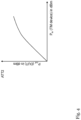
- shows an exemplary AM/AM curve in the context of a high attenuation;
- Fig. 4
- shows an exemplary AM/AM curve in the context of a low attenuation;
- Fig. 5
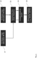
- an exemplary block diagram with respect to functioning regarding the inventive non-linearity determination;
- Fig. 6A
- shows a flow chart of an embodiment of the second aspect of the invention; and
- Fig. 6B
- shows further steps of the embodiment according to
Fig. 6A . - With respect to
Fig. 1 , an exemplary embodiment of theinventive measurement device 10 for performing measurements with respect to at least one device under test is illustrated. Exemplarily, saidmeasurement device 10 comprises afirst port 11a and asecond port 11b for connecting the at least one device under test. It is noted that especially as an alternative, themeasurement device 10 can comprise only one port or at least three ports. - As it can further be seen from
Fig. 1 , themeasurement device 10 comprises adisplay unit 12. Saiddisplay unit 12 or display, respectively, may be configured to display measurement results especially regarding the measurements performed with respect to the at least one device under test and/or information regarding non-linearity of the measurement device. - With respect to the
measurement device 10, it is noted that saidmeasurement device 10 can especially comprise or be a signal analyzer, a vector network analyzer, or an oscilloscope. - In accordance with
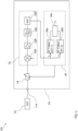
Fig. 2 , themeasurement device 10 according toFig. 1 is shown in greater detail in combination with theinventive measurement system 20 comprising saidmeasurement device 10 and at least one device under test, exemplarily the device undertest 13. In this context, said device undertest 13 is exemplarily connected to thefirst port 11a of themeasurement device 10, wherein thefirst port 11a is configured to receive a signal from the device undertest 13. - As it can be seen from
Fig. 2 , themeasurement device 10 further comprises a signallevel modification unit 14 for modifying the corresponding level of the signal in order to form a modified signal, wherein the signallevel modification unit 14 is operable in at least a first operation mode and a second operation mode being different from the first operation mode. It is noted that the signallevel modification unit 14 is exemplarily connected to the port or thefirst port 11a, respectively. - Furthermore, the
measurement device 10 comprises a receivingunit 15 for receiving and digitizing the modified signal in order to a form a digitized modified signal. It is noted that said receivingunit 15 is exemplarily connected to the above-mentioned signallevel modification unit 14. - Moreover, the
measurement device 10 comprises aprocessing unit 16 being exemplarily connected to the above-mentioned signallevel modification unit 14 and to the above-mentionedreceiving unit 15. - In this context, the
processing unit 16 is configured to receive a first data stream of the digitized modified signal for the case that the signallevel modification unit 14 is operated in the first operation mode and to receive a second data stream for the case that the signallevel modification unit 14 is operated in the second operation mode. - In addition to this, the
processing unit 16 is configured to determine information regarding non-linearity of the receivingunit 15 on the basis of a comparison of the first data stream and the second data stream. - With respect to the above-mentioned signal, it is noted that said signal may comprise or be a radio frequency signal.
- With respect to the receiving
unit 15, it is noted that the receivingunit 15 may comprise non-linearities and/or at least one non-linear element. - In particular, as it can be seen from
Fig. 2 , the receivingunit 15 exemplarily comprises amixer 15a, anamplifier 15b, afilter 15c, especially a bandpass filter, and an analog-to-digital converter 15d. - In this context, an input of the
mixer 15a is connected to an output of the signallevel modification unit 14, wherein an output of themixer 15a is connected to an input of theamplifier 15b. Furthermore, an output of saidamplifier 15b is connected to an input of thefilter 15c, wherein an output of saidfilter 15c is connected to an input of the analog-to-digital converter 15d. Additionally, an output of the analog-to-digital converter 15d is connected to an input of the above-mentionedprocessing unit 16. - With respect to the signal
level modification unit 14, it is noted that the signallevel modification unit 14 may comprise or be an adjustable attenuation unit or at least one attenuator. It is further noted that the signallevel modification unit 14 may comprise at least one resistive element. Moreover, the adjustable attenuation unit or the at least one attenuator may comprise or be at least one resistive element. - Furthermore, especially in the context of the above-mentioned connection between the signal
level modification unit 14 and theprocessing unit 16, it is noted that the signallevel modification unit 14 may comprise an input, preferably a control input, being especially connected to an output, preferably a control output, of theprocessing unit 16. Accordingly, theprocessing unit 16 can be a control and processing unit. - With respect to the first operation mode, it is noted that the first operation mode comprises applying a first attenuation to the signal.
- With respect to the second operation mode, it is noted that the second operation mode comprises applying a second attenuation to the signal.
- The first attenuation is higher than the second attenuation. Accordingly, in the first operation mode, a high attenuation may be applied to the signal, whereas in the second operation mode, a low attenuation may applied to the signal. Preferably, in the first operation mode, a maximum attenuation of the signal
level modification unit 14 may be enabled, whereas in the second operation mode, an attenuation of the signallevel modification unit 14 may completely be disabled. - In the context of the first attenuation being higher than the second attenuation, it is noted it that it might be particularly advantageous if the first data stream is such that no non-linear effects can be expected, while the second data stream has a level in which non-linearities may be expected, but the SNR is preferably improved.
- Thus, one of the two operating modes may be set for a high signal-to-noise-ratio at the cost of linearity. The second mode allows measuring the non-linear characteristics (contribution) of the device (receiver). These non-linear characteristics are than corrected on the first stream. The corrected first stream is then analyzed to characterize the DUT (e.g. using EVM).
- It is further noted that it might be particularly advantageous if the signal
level modification unit 14 is free of an amplifier and/or a diode. - With respect to the signal, it is noted that it might be particularly advantageous if the signal comprises or is a periodic signal. Accordingly, especially with the aid of the
measurement device 10, the device undertest 13 may be configured to provide a periodic signal. - Furthermore, it might be particularly advantageous if the first data stream and the second data stream comprise the same pattern, preferably a periodic pattern, more preferably a periodic cycle, most preferably the same periodic pattern and/or the same periodic cycle, of the digitized modified signal.
- With respect to the above-mentioned term "the same", it is noted that said term may especially be understood as referring to an analogous portion of the respective signal, wherein the corresponding attenuation preferably differs from each other.
- As it can further be seen from
Fig. 2 , theprocessing unit 16 exemplarily comprises afirst storage element 16a for storing a first pattern, especially a first radio frequency pattern, with respect to the first data stream preferably with the first attenuation (ATT 1), asecond storage element 16b for storing a second pattern, especially a second radio frequency pattern, with respect to the second data stream preferably with the second attenuation (ATT 2), and acomparison element 16c for comparing the first pattern and the second pattern. - With respect to the above-mentioned storing the first pattern and the second pattern, it is noted that this may preferably happen at different time points t 1 and t 2.
- In this context, it is further noted that it does not matter in which order which pattern is stored. In addition to this or as an alternative, the corresponding pattern can be determined on the basis of the pattern already stored especially with the aid of a cross-correlation and/or artificial intelligence.
- Furthermore, especially on the basis of the comparison of the first pattern and the second pattern, the
comparison element 16c may be configured to provide information regarding non-linearity of the receivingunit 15 and/or at least one corresponding compensation value. - For the sake of completeness, it is noted that the above-mentioned input of the
processing unit 16, which is exemplarily connected to the output of the analog-to-digital converter 15d, is exemplarily connected to an input of thefirst storage element 16a and to an input of thesecond storage element 16b. Furthermore, an output of saidfirst storage element 16a is exemplarily connected to a first input of thecomparison element 16c, whereas an output of saidsecond storage element 16b is exemplarily connected to a second input of thecomparison element 16c. The above-mentioned information regarding non-linearity of the receivingunit 15 and/or at least one corresponding compensation value is exemplarily provided at an output of thecomparison element 16c. - Moreover, it is noted that it might be particularly advantageous if the
processing unit 16 is configured to generate an AM/AM table and/or an AM/AM curve (or e.g., an AM/PM table and/or an AM/PM curve), on the basis of the information regarding non-linearity of the receivingunit 15. - In this context, a first axis, especially the x-axis, of the AM/AM curve may comprise an input parameter, especially an input power, of the
measurement device 10. In addition to this or as an alternative, a second axis, especially the y-axis, of the AM/AM curve may comprise an output parameter, especially an output power, of the device undertest 13. Accordingly, the above-mentioned AM/AM table may comprise said first axis and/or said second axis in the form of a table. - Other characterization/compensation methods may be used in addition or instead of such AM/AM or AM/PM approaches, such as memory polynomial, Volterra, Look-up tables or other models known from digital predistortion (DPD).
- In addition to this or as an alternative, it is noted that it might be particularly advantageous if the
processing unit 16 is configured to generate a polynomial form and/or a memory-polynomial form and/or a Volterra form on the basis of the information regarding non-linearity of the receivingunit 15. - With respect to the above-mentioned
display unit 12, it is noted that saiddisplay unit 12 may be configured to visualize the information regarding non-linearity of the receivingunit 15, especially the AM/AM table and/or the AM/AM curve (or an AM/PM table and/or an AM/PM curve), preferably in addition to or as an alternative of corresponding measurement results. - It is further noted that it might be particularly advantageous if the
processing unit 16 is configured to compensate further measurements with respect to the device undertest 13 on the basis of the information regarding non-linearity of the receivingunit 15 and/or with the aid of the above-mentioned at least one corresponding compensation value. - Said information regarding non-linearity of the receiving
unit 15 might be signal-specific. If the device undertest 13 outputs a different signal, then the non-linearity of the receivingunit 15 may be determined once again. However, further measurements of the same device under test and the same signal can then advantageously be compensated by the then known none-linearity of the receivingunit 15. - For the sake of completeness, it is noted that for the case that the
measurement device 10 comprises at least one further port, such as thesecond port 11b as depicted inFig. 1 , for receiving at least one further signal from the device under test or from at least one further device under test, the above-mentioned explanations may analogously apply. - Accordingly, the
measurement device 10 may further comprise at least one further signal level modification unit for modifying the corresponding level of the at least one further signal in order to form at least one further modified signal, the at least one further signal level modification unit being operable in at least at least one further first operation mode and at least one further second operation mode being different from the at least one further first operation mode, and at least one further receiving unit for receiving and digitizing the at least one further modified signal in order to a form at least one further digitized modified signal. - In this context, the
processing unit 16 may be configured to receive at least one further first data stream of the at least one further digitized modified signal for the case that the at least one further signal level modification unit is operated in the at least one further first operation mode and to receive at least one further second data stream for the case that the at least one further signal level modification is operated in the at least one further second operation mode. - In addition to this, the
processing unit 16 may be configured to determine at least one further information regarding non-linearity of the at least one further receiving unit on the basis of a comparison of the at least one further first data stream and the at least one further second data stream. - With respect to the
measurement device 10, it is noted that it might be particularly advantageous if themeasurement device 10 is used for and/or in the context of an error vector magnitude measurement. In addition to this or as an alternative, it might be particularly advantageous if themeasurement device 10 is used for and/or in the context of a measurement requiring a maximum signal-to-noise ratio. - Now, with respect to
Fig. 3 , an exemplary AM/AM curve in the context of the above-mentioned first attenuation is shown. Accordingly, the corresponding attenuation is set very high or maximum. Exemplarily, the signal level Pin measured by the measurement device, such as the above-mentionedmeasurement device 10, changes to the same extent as the signal level Pout at the output of the device under test, such as the above-mentioned device undertest 13, changes. Said device under test does not show any non-linear characteristics in this exemplary case. - In accordance with
Fig. 4 , an exemplary AM/AM curve in the context of the above-mentioned second attenuation is depicted. Accordingly, the corresponding attenuation is set very low or switched off. The signal level Pin measured by the measurement device, such as the above-mentionedmeasurement device 10, changes non-linearly compared to the signal level Pout at the output of the device under test such as the above-mentioned device undertest 13. From this, it can be concluded that the receive path for the measured signal shows non-linear characteristics. - Moreover,
Fig. 5 illustrates an exemplary block diagram with respect to functioning regarding the inventive non-linearity determination or determining the above-mentioned information regarding non-linearities of the receivingunit 15, respectively. - Before said
Fig. 5 is discussed in greater detail, some general explanations regarding the inventive non-linearity determination are made in the following:
Inventively, the first data stream and the second data stream or the first pattern and the second pattern, respectively, are compared with each other. From this, the non-linearity can be determined. If a non-linearity can be recognized in both streams or patterns, respectively, which remains the same in its type, then this comes from the device under test. If no non-linearity can be detected in the stream or pattern, respectively, in which the attenuation has a high value and if linearity can be detected in the stream or pattern, respectively, in which the attenuation has a low value, the non-linearity comes from the measurement device or from components in the corresponding receive path, respectively. This information can be used for further measurements to compensate the measurement signal for the known non-linearity according to the current signal level. - Again, with respect to
Fig. 5 , in accordance with anexemplary block 31, a first I/Q stream especially with a high attenuation is received exemplarily as a reference stream. Furthermore, according to anexemplary block 32, a second I/Q stream especially with a low attenuation is received exemplarily as a measurement stream. - In this context, it is noted it that it might be particularly advantageous if the first I/Q stream is such that no non-linear effects can be expected, while the second I/Q stream has a level in which non-linearities may be expected, but the SNR is preferably improved.
- Especially in the light of the explanations above, it is noted that the above-mentioned first data stream can comprise or be said first I/Q stream, whereas the above-mentioned second data stream can comprise or be said second I/Q stream. Accordingly, said receiving of said I/Q streams may be performed by the above-mentioned
processing unit 16. - With respect to the I/Q streams of
blocks receiving unit 15, which is also used later for the measurement of the device under test such as the above-mentioned device undertest 13. - With respect to the above-mentioned signal, exemplarily received by the above-mentioned
port 11a from the above-mentioned device undertest 13, it is noted that it might be particularly advantageous if said signal comprises or is a modulated signal, especially a modulated communication signal, with a defined bandwidth and a defined amplitude distribution. - In this context, it is noted that the information regarding non-linearity of the above-mentioned
receiving unit 15 is preferably determined at least over the corresponding bandwidth and at least over the corresponding level range of the signal being exemplarily the signal received by the above-mentionedport 11a from the above-mentioned device undertest 13. It might be particularly advantageous if there is an a priori knowledge of said signal. Accordingly, the above-mentionedprocessing unit 16 may be configured to receive the first data stream, exemplarily the first I/Q stream, and/or the second data stream, exemplarily the second I/Q stream, in consideration of the a priori knowledge of the signal. It is noted that said a priori knowledge can be gained through a correlation of at least two respective measurement signals such as the above-mentioned reference stream and the above-mentioned measurement stream. - Again, with respect to the above-mentioned signal, exemplarily received by the above-mentioned
port 11a from the above-mentioned device undertest 13, it is noted that said signal can comprise or be a continuous wave signal. - Before the first I/Q stream and the second I/Q stream are compared exemplarily sample by sample according to block 34, said I/Q streams are, as illustrated by
block 33, synchronized with respect to at least one of time, phase, frequency, or any combination thereof preferably with the aid of the above-mentionedprocessing unit 16. Accordingly, theprocessing unit 16 may be configured to synchronize the first data stream, exemplarily the first I/Q stream, and the second data stream, exemplarily the second I/Q stream, with respect to at least one of time, phase, frequency, or any combination thereof. - Furthermore, especially on the basis of the comparison according to block 34, in accordance with an
exemplary block 35, behavioral modelling is performed preferably with the aid of the above-mentionedprocessing unit 16, thereby exemplarily generating at least one of an AM/AM table, an AM/AM curve, an AM/PM table, an AM/PM curve, or any combination thereof. Accordingly, the above-mentioned determining information regarding non-linearity of the receiving unit may comprise or be based on behavioral modelling. - Finally,
Fig. 6A and6B show a flow chart of an embodiment of the inventive measurement method for performing measurements with respect to a device under test such as the above-mentioned device undertest 13. - A
first step 100 of said method comprises receiving a signal from the device under test especially with the aid of a port of a measurement device such as the above-mentionedport measurement device 10. Asecond step 101 comprises modifying the corresponding level of the signal with the aid of a signal level modification unit, such as the above-mentioned signallevel modification unit 14 of the above-mentionedmeasurement device 10, in order to form a modified signal, the signal level modification unit being operable in at least a first operation mode and a second operation mode being different from the first operation mode. As it can further be seen fromFig. 6A , athird step 102 comprises receiving and digitizing the modified signal with the aid of a receiving unit, such as the above-mentionedreceiving unit 15 of the above-mentionedmeasurement device 10, in order to a form a digitized modified signal. - As it can be seen from
Fig. 6B , afourth step 103 comprises receiving a first data stream of the digitized modified signal for the case that the signal level modification unit is operated in the first operation mode with the aid of a processing unit such as the above-mentionedprocessing unit 16 of the above-mentionedmeasurement device 10. Afifth step 104 comprises receiving a second data stream for the case that the signal level modification unit is operated in the second operation mode with the aid of the processing unit. Furthermore, asixth step 105 comprises determining information regarding non-linearity of the receiving unit on the basis of a comparison of the first data stream and the second data stream with the aid of the processing unit. - While various embodiments of the present invention have been described above, it should be understood that they have been presented by way of example only, and not limitation. Numerous changes to the disclosed embodiments can be made in accordance with the disclosure herein without departing from the spirit or scope of the invention. Thus, the breadth and scope of the present invention should not be limited by any of the above described embodiments. Rather, the scope of the invention should be defined in accordance with the following claims and their equivalents.
- Although the invention has been illustrated and described with respect to one or more implementations, equivalent alterations and modifications will occur to others skilled in the art upon the reading and understanding of this specification and the annexed drawings. In addition, while a particular feature of the invention may have been disclosed with respect to only one of several implementations, such feature may be combined with one or more other features of the other implementations as may be desired and advantageous for any given or particular application.
Claims (14)
- A measurement device (10) for performing measurements with respect to a device under test (13), the measurement device (10) comprising:a port (11a) for receiving a signal from the device under test (13),a signal level modification unit (14) for modifying the corresponding level of the signal in order to form a modified signal, the signal level modification unit (14) being operable in at least a first operation mode and a second operation mode being different, as to its signal level, from the first operation mode,a receiving unit (15) for receiving and digitizing the modified signal in order to a form a digitized modified signal, anda processing unit (16),wherein the processing unit (16) is configured to receive a first data stream of the digitized modified signal for the case that the signal level modification unit (14) is operated in the first operation mode and to receive a second data stream for the case that the signal level modification unit (14) is operated in the second operation mode, and wherein the processing unit (16) is configured to determine information regarding non-linearity of the receiving unit (15) on the basis of a comparison of the first data stream and the second data stream.
- The measurement device (10) according to claim 1, Wherein the signal level of the first operation mode is set, e.g. by an attenuator of the device, such the signal-to-noise-ratio is high but the receiving unit causes non-linearity effects, and the signal level of the second operation mode is set lower, e.g. by an attenuator of the device, such that the receiving unit causes essentially no non-linearity effects.
- The measurement device (10) according to claim 1 or 2,wherein the signal comprises or is a radio frequency signal, and/orwherein the receiving unit (15) comprises non-linearities and/or at least one non-linear element, especially an amplifier (15b) and/or a mixer (15a), and/orwherein the measurement device (10) comprises or is a signal analyzer, a vector network analyzer, or an oscilloscope.
- The measurement device (10) according to any of the preceding claims,wherein the signal level modification unit (14) comprises or is an adjustable attenuation unit or at least one attenuator, and/orwherein the first operation mode comprises applying a first attenuation to the signal, and/orwherein the second operation mode comprises applying a second attenuation to the signal, wherein the first attenuation is preferably higher than the second attenuation.
- The measurement device (10) according to any of the preceding claims,
wherein the signal level modification unit (14) is free of an amplifier and/or a diode. - The measurement device (10) according to any of the claims 1 to 5,
wherein the receiving unit (15) comprises at least one of a filter (15c), an amplifier (15b), a mixer (15a), an analog-to-digital converter (15d), or any combination thereof. - The measurement device (10) according to any of the claims 1 to 6,
wherein the signal comprises or is a periodic signal, and/or wherein the first data stream and the second data stream comprise the same pattern, preferably a periodic pattern, more preferably a periodic cycle, most preferably the same periodic pattern and/or the same periodic cycle, of the digitized modified signal. - The measurement device (10) according to any of the claims 1 to 7,
wherein the processing unit (16) is configured to compensate further measurements with respect to the device under test (13) on the basis of the information regarding non-linearity of the receiving unit (15). - The measurement device (10) according to any of the claims 1 to 8,
wherein the measurement device (10) comprises:at least one further port (11b) for receiving at least one further signal from the device under test or from at least one further device under test,at least one further signal level modification unit for modifying the corresponding level of the at least one further signal in order to form at least one further modified signal, the at least one further signal level modification unit being operable in at least at least one further first operation mode and at least one further second operation mode being different from the at least one further first operation mode,at least one further receiving unit for receiving and digitizing the at least one further modified signal in order to a form at least one further digitized modified signal, wherein the processing unit (16) is configured to receive at least one further first data stream of the at least one further digitized modified signal for the case that the at least one further signal level modification unit is operated in the at least one further first operation mode and to receive at least one further second data stream for the case that the at least one further signal level modification is operated in the at least one further second operation mode, andwherein the processing unit (16) is configured to determine at least one further information regarding non-linearity of the at least one further receiving unit on the basis of a comparison of the at least one further first data stream and the at least one further second data stream. - The measurement device (10) according to any of the claims 1 to 9,
wherein the measurement device (10) is used for and/or in the context of an error vector magnitude measurement, and/or wherein the measurement device (10) is used for and/or in the context of a measurement requiring a maximum signal-to-noise ratio. - A measurement system (20) comprising:a measurement device (10) according to any of the claims 1 to 10, anda device under test (13) connected to said measurement device (10).
- A measurement method for performing measurements with respect to a device under test (13), the measurement method comprising the steps of:receiving (100) a signal from the device under test (13),modifying (101) the corresponding level of the signal with the aid of a signal level modification unit (14) in order to form a modified signal, the signal level modification unit (14) being operable in at least a first operation mode and a second operation mode being different from the first operation mode,receiving (102) and digitizing the modified signal with the aid of a receiving unit (15) in order to a form a digitized modified signal,receiving (103) a first data stream of the digitized modified signal for the case that the signal level modification unit (14) is operated in the first operation mode with the aid of a processing unit (16),receiving (104) a second data stream for the case that the signal level modification unit (14) is operated in the second operation mode with the aid of the processing unit (16), anddetermining (105) information regarding non-linearity of the receiving unit (15) on the basis of a comparison of the first data stream and the second data stream with the aid of the processing unit (16).
- The method of claim 12,
wherein the signal level of the first operation mode is set, e.g. by an attenuator of the device, such the signal-to-noise-ratio is high but the receiving unit causes non-linearity effects, and the signal level of the second operation mode is set lower, e.g. by an attenuator of the device, such that the receiving unit causes essentially no non-linearity effects. - The measurement method according to claim 13,wherein the signal comprises or is a radio frequency signal, and/orwherein the receiving unit (15) comprises non-linearities and/or at least one non-linear element, especially an amplifier (15b) and/or a mixer (15a).
Priority Applications (2)
| Application Number | Priority Date | Filing Date | Title |
|---|---|---|---|
| EP22217261.1A EP4394399B1 (en) | 2022-12-30 | 2022-12-30 | Measurement device for performing measurements with respect to a dut |
| US18/512,782 US12681066B2 (en) | 2022-12-30 | 2023-11-17 | Measurement device for performing measurements with respect to a DUT |
Applications Claiming Priority (1)
| Application Number | Priority Date | Filing Date | Title |
|---|---|---|---|
| EP22217261.1A EP4394399B1 (en) | 2022-12-30 | 2022-12-30 | Measurement device for performing measurements with respect to a dut |
Publications (2)
| Publication Number | Publication Date |
|---|---|
| EP4394399A1 true EP4394399A1 (en) | 2024-07-03 |
| EP4394399B1 EP4394399B1 (en) | 2025-03-19 |
Family
ID=84767242
Family Applications (1)
| Application Number | Title | Priority Date | Filing Date |
|---|---|---|---|
| EP22217261.1A Active EP4394399B1 (en) | 2022-12-30 | 2022-12-30 | Measurement device for performing measurements with respect to a dut |
Country Status (2)
| Country | Link |
|---|---|
| US (1) | US12681066B2 (en) |
| EP (1) | EP4394399B1 (en) |
Citations (4)
| Publication number | Priority date | Publication date | Assignee | Title |
|---|---|---|---|---|
| US6405147B1 (en) * | 1999-09-10 | 2002-06-11 | Condor Systems, Inc. | Signal transfer device measurement system and method |
| US6567762B2 (en) | 2000-12-22 | 2003-05-20 | Agilent Technologies, Inc. | Dynamic range extension apparatus and method |
| US20090058521A1 (en) | 2007-08-31 | 2009-03-05 | Fernandez Andrew D | System and method of digital linearization in electronic devices |
| WO2015089090A1 (en) * | 2013-12-09 | 2015-06-18 | Qualcomm Incorporated | Quantitative characterization of nonlinearity and memory effect in nonlinear circuits |
Family Cites Families (11)
| Publication number | Priority date | Publication date | Assignee | Title |
|---|---|---|---|---|
| US6393372B1 (en) * | 1999-05-17 | 2002-05-21 | Eugene Rzyski | Automated frequency stepping noise measurement system |
| JP4230367B2 (en) * | 2004-01-13 | 2009-02-25 | シャープ株式会社 | Variable gain amplifier, carrier detection circuit system, and infrared remote control receiver using the same |
| JP2005308511A (en) * | 2004-04-21 | 2005-11-04 | Agilent Technol Inc | Method and apparatus for measuring phase noise |
| US8965727B2 (en) * | 2005-05-20 | 2015-02-24 | Omniphase Research Laboratories, Inc. | Intelligent low noise design |
| WO2011047699A1 (en) * | 2009-10-21 | 2011-04-28 | Verigy (Singapore) Pte. Ltd. | Test device and test method for measuring a phase noise of a test signal |
| GB2508911A (en) * | 2012-12-14 | 2014-06-18 | Renesas Mobile Corp | Calibration of a frequency converter, based on non-dc measurements, to reduce an output dc component arising from local oscillator leakage and self-mixing |
| JP5771641B2 (en) * | 2013-03-28 | 2015-09-02 | アンリツ株式会社 | Signal analysis apparatus and signal analysis method |
| US10120008B2 (en) * | 2013-08-29 | 2018-11-06 | Keysight Technologies, Inc. | Method and apparatus for estimating the noise introduced by a device |
| EP3352388B1 (en) * | 2017-01-19 | 2024-03-06 | Rohde & Schwarz GmbH & Co. KG | System and method for processing an electromagnetic signal |
| JP7647622B2 (en) * | 2022-02-22 | 2025-03-18 | 三菱電機株式会社 | Semiconductor device and method for manufacturing the same |
| US12025638B1 (en) * | 2022-09-14 | 2024-07-02 | Keysight Technologies, Inc. | Noise reduction of oscilloscope waveforms |
-
2022
- 2022-12-30 EP EP22217261.1A patent/EP4394399B1/en active Active
-
2023
- 2023-11-17 US US18/512,782 patent/US12681066B2/en active Active
Patent Citations (4)
| Publication number | Priority date | Publication date | Assignee | Title |
|---|---|---|---|---|
| US6405147B1 (en) * | 1999-09-10 | 2002-06-11 | Condor Systems, Inc. | Signal transfer device measurement system and method |
| US6567762B2 (en) | 2000-12-22 | 2003-05-20 | Agilent Technologies, Inc. | Dynamic range extension apparatus and method |
| US20090058521A1 (en) | 2007-08-31 | 2009-03-05 | Fernandez Andrew D | System and method of digital linearization in electronic devices |
| WO2015089090A1 (en) * | 2013-12-09 | 2015-06-18 | Qualcomm Incorporated | Quantitative characterization of nonlinearity and memory effect in nonlinear circuits |
Also Published As
| Publication number | Publication date |
|---|---|
| US20240219442A1 (en) | 2024-07-04 |
| US12681066B2 (en) | 2026-07-14 |
| EP4394399B1 (en) | 2025-03-19 |
Similar Documents
| Publication | Publication Date | Title |
|---|---|---|
| US6594604B2 (en) | S-parameter measurement system for wideband non-linear networks | |
| KR101407354B1 (en) | Compensation for harmonic distortion in the device channel | |
| US20110254721A1 (en) | Method for Compensating a Frequency Characteristic of an Arbitrary Waveform Generator | |
| US6768349B2 (en) | Multiple-output arbitrary waveform generator and mixed lsi tester | |
| CA2372800C (en) | Automated frequency stepping noise measurement test system | |
| US8788234B2 (en) | Method of calibrating interleaved digitizer channels | |
| EP3767309B1 (en) | Measurement system and method for automated measurement of several contributions to signal degradation | |
| CN102857311A (en) | Apparatus for generation of corrected vector wideband RF signals | |
| US12216151B2 (en) | Measurement instrument, measurement system, and testing method of testing a device under test | |
| JP2008286699A (en) | Signal input / output device, test device, and electronic device | |
| JP2002005974A (en) | How to display quality-based measurement results | |
| US20110102080A1 (en) | Systems and methods for distortion measurement using distortion-to-amplitude transformations | |
| US20230412276A1 (en) | Multi-waveform digital predistortion calibration | |
| EP4394399B1 (en) | Measurement device for performing measurements with respect to a dut | |
| US10826616B2 (en) | Reconfigurable digital predistortion circuit | |
| US11119145B2 (en) | Performance testing method and measurement system | |
| US7171324B1 (en) | System and method for removing measurement errors from measurement systems | |
| US10469292B1 (en) | Apparatus and method for characterizing amplifiers in decision feedback equalizers | |
| US7224746B2 (en) | Pre-compensation for digital bit streams | |
| US20060223440A1 (en) | Low frequency noise source and method of calibration thereof | |
| US9093959B2 (en) | Integrated signal analyzer for adaptive control of mixed-signal integrated circuits | |
| CN121727659B (en) | A high-speed, high-dynamic radio frequency calibration device | |
| KR101750699B1 (en) | A method for ADC(analog-digital converter) circuit monitoring using DAC(digital-analog converter) circuit | |
| US12355498B2 (en) | Measurement application device calibration unit, measurement system, method | |
| US20030233599A1 (en) | Method and apparatus for measuring group delay of a device under test |
Legal Events
| Date | Code | Title | Description |
|---|---|---|---|
| PUAI | Public reference made under article 153(3) epc to a published international application that has entered the european phase |
Free format text: ORIGINAL CODE: 0009012 |
|
| STAA | Information on the status of an ep patent application or granted ep patent |
Free format text: STATUS: THE APPLICATION HAS BEEN PUBLISHED |
|
| STAA | Information on the status of an ep patent application or granted ep patent |
Free format text: STATUS: REQUEST FOR EXAMINATION WAS MADE |
|
| AK | Designated contracting states |
Kind code of ref document: A1 Designated state(s): AL AT BE BG CH CY CZ DE DK EE ES FI FR GB GR HR HU IE IS IT LI LT LU LV MC ME MK MT NL NO PL PT RO RS SE SI SK SM TR |
|
| 17P | Request for examination filed |
Effective date: 20240611 |
|
| RBV | Designated contracting states (corrected) |
Designated state(s): AL AT BE BG CH CY CZ DE DK EE ES FI FR GB GR HR HU IE IS IT LI LT LU LV MC ME MK MT NL NO PL PT RO RS SE SI SK SM TR |
|
| GRAP | Despatch of communication of intention to grant a patent |
Free format text: ORIGINAL CODE: EPIDOSNIGR1 |
|
| STAA | Information on the status of an ep patent application or granted ep patent |
Free format text: STATUS: GRANT OF PATENT IS INTENDED |
|
| INTG | Intention to grant announced |
Effective date: 20241126 |
|
| RIN1 | Information on inventor provided before grant (corrected) |
Inventor name: RAMIAN, FLORIAN Inventor name: SANDER, KAY-UWE |
|
| GRAS | Grant fee paid |
Free format text: ORIGINAL CODE: EPIDOSNIGR3 |
|
| RBV | Designated contracting states (corrected) |
Designated state(s): AL AT BE BG CY CZ DE DK EE ES FI FR GB GR HR HU IS IT LT LU LV MC ME MK MT NL NO PL PT RO RS SE SI SK SM TR |
|
| GRAA | (expected) grant |
Free format text: ORIGINAL CODE: 0009210 |
|
| STAA | Information on the status of an ep patent application or granted ep patent |
Free format text: STATUS: THE PATENT HAS BEEN GRANTED |
|
| AK | Designated contracting states |
Kind code of ref document: B1 Designated state(s): AL AT BE BG CY CZ DE DK EE ES FI FR GB GR HR HU IS IT LT LU LV MC ME MK MT NL NO PL PT RO RS SE SI SK SM TR |
|
| P01 | Opt-out of the competence of the unified patent court (upc) registered |
Free format text: CASE NUMBER: APP_7345/2025 Effective date: 20250212 |
|
| REG | Reference to a national code |
Ref country code: GB Ref legal event code: FG4D |
|
| REG | Reference to a national code |
Ref country code: DE Ref legal event code: R096 Ref document number: 602022011952 Country of ref document: DE |
|
| PG25 | Lapsed in a contracting state [announced via postgrant information from national office to epo] |
Ref country code: RS Free format text: LAPSE BECAUSE OF FAILURE TO SUBMIT A TRANSLATION OF THE DESCRIPTION OR TO PAY THE FEE WITHIN THE PRESCRIBED TIME-LIMIT Effective date: 20250619 |
|
| PG25 | Lapsed in a contracting state [announced via postgrant information from national office to epo] |
Ref country code: FI Free format text: LAPSE BECAUSE OF FAILURE TO SUBMIT A TRANSLATION OF THE DESCRIPTION OR TO PAY THE FEE WITHIN THE PRESCRIBED TIME-LIMIT Effective date: 20250319 |
|
| REG | Reference to a national code |
Ref country code: LT Ref legal event code: MG9D |
|
| PG25 | Lapsed in a contracting state [announced via postgrant information from national office to epo] |
Ref country code: NO Free format text: LAPSE BECAUSE OF FAILURE TO SUBMIT A TRANSLATION OF THE DESCRIPTION OR TO PAY THE FEE WITHIN THE PRESCRIBED TIME-LIMIT Effective date: 20250619 |
|
| PG25 | Lapsed in a contracting state [announced via postgrant information from national office to epo] |
Ref country code: HR Free format text: LAPSE BECAUSE OF FAILURE TO SUBMIT A TRANSLATION OF THE DESCRIPTION OR TO PAY THE FEE WITHIN THE PRESCRIBED TIME-LIMIT Effective date: 20250319 |
|
| PG25 | Lapsed in a contracting state [announced via postgrant information from national office to epo] |
Ref country code: LV Free format text: LAPSE BECAUSE OF FAILURE TO SUBMIT A TRANSLATION OF THE DESCRIPTION OR TO PAY THE FEE WITHIN THE PRESCRIBED TIME-LIMIT Effective date: 20250319 |
|
| PG25 | Lapsed in a contracting state [announced via postgrant information from national office to epo] |
Ref country code: BG Free format text: LAPSE BECAUSE OF FAILURE TO SUBMIT A TRANSLATION OF THE DESCRIPTION OR TO PAY THE FEE WITHIN THE PRESCRIBED TIME-LIMIT Effective date: 20250319 Ref country code: GR Free format text: LAPSE BECAUSE OF FAILURE TO SUBMIT A TRANSLATION OF THE DESCRIPTION OR TO PAY THE FEE WITHIN THE PRESCRIBED TIME-LIMIT Effective date: 20250620 |
|
| REG | Reference to a national code |
Ref country code: NL Ref legal event code: MP Effective date: 20250319 |
|
| PG25 | Lapsed in a contracting state [announced via postgrant information from national office to epo] |
Ref country code: NL Free format text: LAPSE BECAUSE OF FAILURE TO SUBMIT A TRANSLATION OF THE DESCRIPTION OR TO PAY THE FEE WITHIN THE PRESCRIBED TIME-LIMIT Effective date: 20250319 |
|
| PG25 | Lapsed in a contracting state [announced via postgrant information from national office to epo] |
Ref country code: SE Free format text: LAPSE BECAUSE OF FAILURE TO SUBMIT A TRANSLATION OF THE DESCRIPTION OR TO PAY THE FEE WITHIN THE PRESCRIBED TIME-LIMIT Effective date: 20250319 |
|
| PG25 | Lapsed in a contracting state [announced via postgrant information from national office to epo] |
Ref country code: SM Free format text: LAPSE BECAUSE OF FAILURE TO SUBMIT A TRANSLATION OF THE DESCRIPTION OR TO PAY THE FEE WITHIN THE PRESCRIBED TIME-LIMIT Effective date: 20250319 |
|
| PG25 | Lapsed in a contracting state [announced via postgrant information from national office to epo] |
Ref country code: ES Free format text: LAPSE BECAUSE OF FAILURE TO SUBMIT A TRANSLATION OF THE DESCRIPTION OR TO PAY THE FEE WITHIN THE PRESCRIBED TIME-LIMIT Effective date: 20250319 Ref country code: PT Free format text: LAPSE BECAUSE OF FAILURE TO SUBMIT A TRANSLATION OF THE DESCRIPTION OR TO PAY THE FEE WITHIN THE PRESCRIBED TIME-LIMIT Effective date: 20250721 |
|
| PG25 | Lapsed in a contracting state [announced via postgrant information from national office to epo] |
Ref country code: PL Free format text: LAPSE BECAUSE OF FAILURE TO SUBMIT A TRANSLATION OF THE DESCRIPTION OR TO PAY THE FEE WITHIN THE PRESCRIBED TIME-LIMIT Effective date: 20250319 Ref country code: IT Free format text: LAPSE BECAUSE OF FAILURE TO SUBMIT A TRANSLATION OF THE DESCRIPTION OR TO PAY THE FEE WITHIN THE PRESCRIBED TIME-LIMIT Effective date: 20250319 |
|
| PG25 | Lapsed in a contracting state [announced via postgrant information from national office to epo] |
Ref country code: AT Free format text: LAPSE BECAUSE OF FAILURE TO SUBMIT A TRANSLATION OF THE DESCRIPTION OR TO PAY THE FEE WITHIN THE PRESCRIBED TIME-LIMIT Effective date: 20250319 |
|
| PG25 | Lapsed in a contracting state [announced via postgrant information from national office to epo] |
Ref country code: CZ Free format text: LAPSE BECAUSE OF FAILURE TO SUBMIT A TRANSLATION OF THE DESCRIPTION OR TO PAY THE FEE WITHIN THE PRESCRIBED TIME-LIMIT Effective date: 20250319 Ref country code: EE Free format text: LAPSE BECAUSE OF FAILURE TO SUBMIT A TRANSLATION OF THE DESCRIPTION OR TO PAY THE FEE WITHIN THE PRESCRIBED TIME-LIMIT Effective date: 20250319 |
|
| PG25 | Lapsed in a contracting state [announced via postgrant information from national office to epo] |
Ref country code: RO Free format text: LAPSE BECAUSE OF FAILURE TO SUBMIT A TRANSLATION OF THE DESCRIPTION OR TO PAY THE FEE WITHIN THE PRESCRIBED TIME-LIMIT Effective date: 20250319 |
|
| PG25 | Lapsed in a contracting state [announced via postgrant information from national office to epo] |
Ref country code: SK Free format text: LAPSE BECAUSE OF FAILURE TO SUBMIT A TRANSLATION OF THE DESCRIPTION OR TO PAY THE FEE WITHIN THE PRESCRIBED TIME-LIMIT Effective date: 20250319 |
|
| PG25 | Lapsed in a contracting state [announced via postgrant information from national office to epo] |
Ref country code: IS Free format text: LAPSE BECAUSE OF FAILURE TO SUBMIT A TRANSLATION OF THE DESCRIPTION OR TO PAY THE FEE WITHIN THE PRESCRIBED TIME-LIMIT Effective date: 20250719 |
|
| REG | Reference to a national code |
Ref country code: DE Ref legal event code: R097 Ref document number: 602022011952 Country of ref document: DE |
|
| PG25 | Lapsed in a contracting state [announced via postgrant information from national office to epo] |
Ref country code: DK Free format text: LAPSE BECAUSE OF FAILURE TO SUBMIT A TRANSLATION OF THE DESCRIPTION OR TO PAY THE FEE WITHIN THE PRESCRIBED TIME-LIMIT Effective date: 20250319 |
|
| PGFP | Annual fee paid to national office [announced via postgrant information from national office to epo] |
Ref country code: FR Payment date: 20251217 Year of fee payment: 4 |
|
| PLBE | No opposition filed within time limit |
Free format text: ORIGINAL CODE: 0009261 |
|
| STAA | Information on the status of an ep patent application or granted ep patent |
Free format text: STATUS: NO OPPOSITION FILED WITHIN TIME LIMIT |
|
| 26N | No opposition filed |
Effective date: 20251222 |
|
| PGFP | Annual fee paid to national office [announced via postgrant information from national office to epo] |
Ref country code: DE Payment date: 20251222 Year of fee payment: 4 |
|
| PG25 | Lapsed in a contracting state [announced via postgrant information from national office to epo] |
Ref country code: LT Free format text: LAPSE BECAUSE OF FAILURE TO SUBMIT A TRANSLATION OF THE DESCRIPTION OR TO PAY THE FEE WITHIN THE PRESCRIBED TIME-LIMIT Effective date: 20250319 |
|
| PG25 | Lapsed in a contracting state [announced via postgrant information from national office to epo] |
Ref country code: MC Free format text: LAPSE BECAUSE OF FAILURE TO SUBMIT A TRANSLATION OF THE DESCRIPTION OR TO PAY THE FEE WITHIN THE PRESCRIBED TIME-LIMIT Effective date: 20250319 |