EP4394388A1 - Conveying device, specimen analysis system provided with conveying device, and specimen pretreatment device provided with conveying device - Google Patents
Conveying device, specimen analysis system provided with conveying device, and specimen pretreatment device provided with conveying device Download PDFInfo
- Publication number
- EP4394388A1 EP4394388A1 EP22861002.8A EP22861002A EP4394388A1 EP 4394388 A1 EP4394388 A1 EP 4394388A1 EP 22861002 A EP22861002 A EP 22861002A EP 4394388 A1 EP4394388 A1 EP 4394388A1
- Authority
- EP
- European Patent Office
- Prior art keywords
- specimen
- electromagnetic actuators
- conveying device
- conveyed object
- magnetic circuit
- Prior art date
- Legal status (The legal status is an assumption and is not a legal conclusion. Google has not performed a legal analysis and makes no representation as to the accuracy of the status listed.)
- Pending
Links
Images



Classifications
-
- B—PERFORMING OPERATIONS; TRANSPORTING
- B65—CONVEYING; PACKING; STORING; HANDLING THIN OR FILAMENTARY MATERIAL
- B65G—TRANSPORT OR STORAGE DEVICES, e.g. CONVEYORS FOR LOADING OR TIPPING, SHOP CONVEYOR SYSTEMS OR PNEUMATIC TUBE CONVEYORS
- B65G54/00—Non-mechanical conveyors not otherwise provided for
- B65G54/02—Non-mechanical conveyors not otherwise provided for electrostatic, electric, or magnetic
-
- G—PHYSICS
- G01—MEASURING; TESTING
- G01N—INVESTIGATING OR ANALYSING MATERIALS BY DETERMINING THEIR CHEMICAL OR PHYSICAL PROPERTIES
- G01N35/00—Automatic analysis not limited to methods or materials provided for in any single one of groups G01N1/00 - G01N33/00; Handling materials therefor
- G01N35/02—Automatic analysis not limited to methods or materials provided for in any single one of groups G01N1/00 - G01N33/00; Handling materials therefor using a plurality of sample containers moved by a conveyor system past one or more treatment or analysis stations
- G01N35/04—Details of the conveyor system
-
- G—PHYSICS
- G01—MEASURING; TESTING
- G01N—INVESTIGATING OR ANALYSING MATERIALS BY DETERMINING THEIR CHEMICAL OR PHYSICAL PROPERTIES
- G01N35/00—Automatic analysis not limited to methods or materials provided for in any single one of groups G01N1/00 - G01N33/00; Handling materials therefor
- G01N35/02—Automatic analysis not limited to methods or materials provided for in any single one of groups G01N1/00 - G01N33/00; Handling materials therefor using a plurality of sample containers moved by a conveyor system past one or more treatment or analysis stations
- G01N35/04—Details of the conveyor system
- G01N2035/0474—Details of actuating means for conveyors or pipettes
- G01N2035/0477—Magnetic
Definitions
- PLT 1 discloses a distribution system which conveys a plurality of container carriers on top of a conveyance plane.
- a plurality of electromagnetic actuators is disposed below the conveyance plane, and by the electromagnetic actuators being driven by a control device, the container carriers are conveyed in desired directions on the conveyance plane.
- a test of an instructed analysis item is conducted to a specimen such as blood, plasma, serum, urine, and other body fluid.
- a specimen such as blood, plasma, serum, urine, and other body fluid.
- devices with a plurality of functions are connected one another so that the respective processings can automatically be carried out. That is, for work efficiency in a laboratory, an analysis section of a plurality of analysis fields such as biochemistry and immunity, and a pretreatment section which performs pretreatment necessary for the analysis are connected one another through a conveyance line, thus being operated as a single system.
- a conveyance line used in a conventional specimen analysis system is mainly a belt-driven type.
- Such a belt-driven type has a problem that, when conveyance stops due to some kind of abnormality during the conveyance, a specimen cannot be supplied to a device on a downstream side. Therefore, paying close attention to wearing of a belt is necessary.
- the present invention includes a plurality of measures for solving the above problem, and one example thereof is a conveying device in which a plurality of magnetic circuit sections each including electromagnetic actuators arranged in a grid pattern are connected one another, each electromagnetic actuator including a tooth made of a magnetic material and a winding wire wound around the tooth.
- Each of the magnetic circuit sections has a substantially quadrilateral shape, and includes a plurality of first electromagnetic actuators disposed along one of sides opposed one another, a plurality of second electromagnetic actuators disposed along an other one of the sides opposed one another, a plurality of third electromagnetic actuators disposed along one of other sides opposed one another, and a plurality of fourth electromagnetic actuators disposed along an other one of the other sides opposed one another.
- the reagent tray 114 is a member where a reagent is placed when reagent registration into the specimen analysis system 100 is conducted.
- the reagent ID reader 115 is a device which acquires reagent information by reading a reagent ID given to the reagent placed at the reagent tray 114.
- the reagent loader 116 is a device which loads the reagent to the reagent disc 110.
- the daughter-specimen container preparation unit 159 is a unit which performs preparation necessary for dispensing, at the subsequent dispenser unit 160, the specimen contained in the fed specimen container 122.
- the dispenser unit 160 is a unit which subdivides, for analysis by the specimen analysis system etc., the specimen applied with the centrifugal separation, and also attaches a barcode etc., to the subdivided specimen container 122 (hereinafter, the subdivided specimen container 122 is referred to as a daughter-specimen container 122).
- the transfer unit 161 is a unit which classifies the dispensed daughter-specimen container 122, and performs transfer preparation to the specimen analysis system 100.
- the closure unit 152 is a unit which closes the specimen container 122 and the daughter-specimen container 122.
- the specimen storage unit 153 is a unit which stores the closed specimen container 122.
Landscapes
- Physics & Mathematics (AREA)
- Health & Medical Sciences (AREA)
- Life Sciences & Earth Sciences (AREA)
- Chemical & Material Sciences (AREA)
- Analytical Chemistry (AREA)
- Biochemistry (AREA)
- General Health & Medical Sciences (AREA)
- General Physics & Mathematics (AREA)
- Immunology (AREA)
- Pathology (AREA)
- Non-Mechanical Conveyors (AREA)
- Automatic Analysis And Handling Materials Therefor (AREA)
Abstract
Description
- The present invention relates to a conveying device suitable for a specimen analysis system which performs analysis of a biological sample, for example, blood, urine, etc. (hereinafter, referred to as a specimen), and for a specimen pretreatment device which performs pretreatment necessary for the analysis, and to the specimen analysis system and the specimen pretreatment device provided with the conveying device.
- PLT 1 discloses a distribution system which conveys a plurality of container carriers on top of a conveyance plane. A plurality of electromagnetic actuators is disposed below the conveyance plane, and by the electromagnetic actuators being driven by a control device, the container carriers are conveyed in desired directions on the conveyance plane.
- PTL 1:
JP2015-502525A - In a specimen analysis system for clinical laboratory testing, a test of an instructed analysis item is conducted to a specimen such as blood, plasma, serum, urine, and other body fluid. In the specimen analysis system, devices with a plurality of functions are connected one another so that the respective processings can automatically be carried out. That is, for work efficiency in a laboratory, an analysis section of a plurality of analysis fields such as biochemistry and immunity, and a pretreatment section which performs pretreatment necessary for the analysis are connected one another through a conveyance line, thus being operated as a single system.
- A conveyance line used in a conventional specimen analysis system is mainly a belt-driven type. Such a belt-driven type has a problem that, when conveyance stops due to some kind of abnormality during the conveyance, a specimen cannot be supplied to a device on a downstream side. Therefore, paying close attention to wearing of a belt is necessary.
- Advance in medical care and progress in aging society have enhanced importance of processing specimens. Hence, in order to improve analysis processing ability of the specimen analysis system, high-speed conveyance, mass simultaneous conveyance, and multiple-direction conveyance of specimens are desired. One example of a technique which realizes such conveyance includes a technique to convey a conveyed object by using magnetic force (see PTL 1).
- As illustrated in
FIG. 2 ofPTL 1, the electromagnetic actuators ofPTL 1 are arranged in a grid pattern. At a left side and a lower side of a sub-plane inFIG. 2 , the electromagnetic actuators are arranged at a pitch of g2. On the other hand, at a right side and an upper side of the conveyance plane inFIG. 2 , the electromagnetic actuators are arranged at a pitch of g1 (= g2/2). - Although
PTL 1 discloses a configuration in which the conveyance plane is formed by combination of a plurality of sub-planes, how the sub-planes are connected to each other is not disclosed. When the sub-planes are connected such that parts of the sub-planes, where the electromagnetic actuators are dense, are adjacent to each other, or parts of the sub-planes, where the electromagnetic actuators are sparse, are adjacent to each other, inductance characteristics at the connected region differ from inductance characteristics at the other region. As a result, there is a problem that a conveyed object cannot stably be conveyed due to variation in thrust applied to the conveyed object, or degradation in estimation accuracy of a position of the conveyed object. - The present invention includes a plurality of measures for solving the above problem, and one example thereof is a conveying device in which a plurality of magnetic circuit sections each including electromagnetic actuators arranged in a grid pattern are connected one another, each electromagnetic actuator including a tooth made of a magnetic material and a winding wire wound around the tooth. Each of the magnetic circuit sections has a substantially quadrilateral shape, and includes a plurality of first electromagnetic actuators disposed along one of sides opposed one another, a plurality of second electromagnetic actuators disposed along an other one of the sides opposed one another, a plurality of third electromagnetic actuators disposed along one of other sides opposed one another, and a plurality of fourth electromagnetic actuators disposed along an other one of the other sides opposed one another. The number of the first electromagnetic actuators is larger than the number of the second electromagnetic actuators. The number of the third electromagnetic actuators is larger than the number of the fourth electromagnetic actuators. The plurality of magnetic circuit sections are connected one another such that the side having the larger number of the electromagnetic actuators and the side having the smaller number of the electromagnetic actuators are adjacent to each other.
- According to the present invention, the plurality of magnetic circuit sections are connected one another such that the side having the larger number of the electromagnetic actuators and the side having the smaller number of the electromagnetic actuators are adjacent to each other. Therefore, it can be suppressed that inductance characteristics at the connected region differ from inductance characteristics at the other region. As a result, in the connected region, variation in thrust applied to the conveyed object, and degradation in estimation accuracy of a position of the conveyed object can be suppressed, and thereby the conveyed object can stably be conveyed.
-
- [
FIG. 1] FIG. 1 is a view illustrating a configuration of a conveying device ofEmbodiment 1. - [
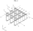
FIG. 2] FIG. 2 is a perspective view illustrating a magnetic circuit section of the conveying device ofEmbodiment 1. - [
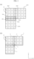
FIG. 3] FIG. 3 is a diagram illustrating a connecting example of magnetic circuit sections of each of a conventional conveying device and the conveying device ofEmbodiment 1. - [
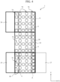
FIG. 4] FIG. 4 is a diagram illustrating a connecting example of magnetic circuit sections of a conveying device ofEmbodiment 2. - [
FIG. 5] FIG. 5 is a diagram illustrating a configuration of a conveying system. - [
FIG. 6] FIG. 6 is a diagram illustrating a configuration of a specimen analysis system. - [
FIG. 7] FIG. 7 is a diagram illustrating a configuration of a specimen pretreatment device. - Hereinafter, embodiments of a conveying device, and a specimen analysis system and a specimen pretreatment device provided with the same are described with reference to the drawings.
- A conveying device of
Embodiment 1 is described.FIG. 1 is a view illustrating a configuration of the conveying device ofEmbodiment 1. Theconveying device 1 is a conveying device which conveys a conveyedobject 10 in an X direction and a Y direction.FIG. 2 is a perspective view illustrating a magnetic circuit section of the conveying device ofEmbodiment 1. In a case of conveyance in a long distance, a plurality ofconveying devices 1 illustrated inFIG. 1 are connected one another in the X direction and/or the Y direction to achieve the long-distance conveyance of the conveyedobject 10. Aconveyance surface 15 is placed on amagnetic circuit section 2, and a permanent magnet 11 (see FIG. 8) made of a magnetic material and embedded in the conveyedobject 10 moves on top of theconveyance surface 15. Themagnetic circuit section 2 illustrated in FIG. 2(a) includes three conveyance lines to convey the conveyedobject 10 in the X direction, and three conveyance lines to convey the conveyedobject 10 in the Y direction. Each of a plurality ofteeth 20 made of a magnetic material and having a cylindrical shape, is wound with a windingwire 30. Note that thetooth 20 is a general term for atooth 20a to atooth 20d. The plurality ofteeth 20 is magnetically coupled one another at an opposite side (-Z side) from theconveyance surface 15 by ayoke 40 made of a magnetic material. Thetooth 20 wound with the winding wire is referred to as anelectromagnetic actuator 70. A plurality ofelectromagnetic actuators 70 are arranged in a grid pattern. - The
yoke 40 is formed to have a grid pattern corresponding to the three conveyer lines formed along the X direction, and the three conveyer lines formed along the Y direction. Theyoke 40 is made of a magnetic material and is magnetically coupled to the plurality of teeth. Theyoke 40 supports the plurality ofteeth 20 such that the plurality ofteeth 20 extends in a Z direction. - The
teeth 20 include atooth 20a with one tooth adjacent thereto, atooth 20b with two teeth adjacent thereto, atooth 20c with three teeth adjacent thereto, and atooth 20d with four teeth adjacent thereto. Thetooth 20a is a tooth disposed at the outermost side. Thetooth 20a is adjacent to another tooth at only one side in one of the X direction and the Y direction. Thetooth 20b is adjacent to another tooth at each side in the X direction or the Y direction. Thetooth 20c is adjacent to another tooth at each side in one of the X direction and the Y direction, and at one side in the other one of the X direction and the Y direction. Thetooth 20c is adjacent to another tooth at each side in the X direction and at each side in the Y direction. - The
teeth tooth 20a has less adjacent teeth comparing to theteeth 20b to 20d. Therefore, a magnetic flux density generated when a certain current is supplied to the windingwire 30 is smaller than the case of theteeth 20b to 20d. Thus, thrust which acts on the conveyedobject 10 at thetooth 20a is smaller. In addition, a current value when a certain voltage is applied also varies between the windingwire 30 of thetooth 20a and the windingwires 30 of theteeth 20b to 20d, which also varies a magnetic saturation level. Therefore, a problem of deterioration in detection accuracy of a position of a conveyed object by utilizing magnetic saturation may occur. - The
magnetic circuit section 2 has a substantially quadrilateral shape, where a side X1 and a side X2 which configure the substantially quadrilateral shape are opposed one another, and a side Y1 and a side Y2 which configure the substantially quadrilateral shape are opposed one another. The number of the plurality ofelectromagnetic actuators 70 disposed along the one side X1 (six in Embodiment 1) is larger than the number of the plurality ofelectromagnetic actuators 70 disposed along the other side X2 (three in Embodiment 1). Moreover, the number of the plurality ofelectromagnetic actuators 70 disposed along the one side Y1 (six in Embodiment 1) is larger than the number of the plurality ofelectromagnetic actuators 70 disposed along the other side Y2 (three in Embodiment 1). - The plurality of
electromagnetic actuators 70 disposed along the side X1 are disposed to be adjacent to each other. Moreover, the plurality ofelectromagnetic actuators 70 disposed along the side X2 are disposed having a gap therebetween. That is, a pitch between the plurality ofelectromagnetic actuators 70 disposed along the side X1 is smaller than a pitch between the plurality ofelectromagnetic actuators 70 disposed along the side X2. Similarly, the plurality ofelectromagnetic actuators 70 disposed along the side Y1 are disposed to be adjacent to each other. Moreover, the plurality ofelectromagnetic actuators 70 disposed along the side Y2 are disposed having a gap therebetween. That is, a pitch between the plurality ofelectromagnetic actuators 70 disposed along the side Y1 is smaller than a pitch between the plurality ofelectromagnetic actuators 70 disposed along the side Y2. -
FIG. 3 is a diagram illustrating a connecting example of magnetic circuit sections of each of a conventional conveying device and the conveying device ofEmbodiment 1.FIG. 3(a) a diagram showing the connecting example of the magnetic circuit sections of the conventional conveying device.FIG. 3(b) is a diagram showing the connecting example of the magnetic circuit sections of the conveying device ofEmbodiment 1. - A conventional conveying
device 1000 inFIG. 3(a) includes threemagnetic circuit sections 2000. The threemagnetic circuit sections 2000 are connected one another to form an L-shape. When the conventionalmagnetic circuit sections 2000 have a desired formation, density of theelectromagnetic actuators 70 in aconnected region 4000 between themagnetic circuit sections 2000 is low. Therefore, in theconnected region 4000 of the conventional conveyingdevice 1000, thrust applied to the conveyedobject 10 may vary, or estimation accuracy of a position of the conveyedobject 10 may degrade. As a result, during conveyance of the conveyedobject 10, the conveyedobject 10 may sway or swing, deviate from a conveyance surface of the conveyingdevice 1000, or damage the conveyance surface. - The conveying
device 1 ofEmbodiment 1 includes threemagnetic circuit section 2 described with reference toFIG. 2 . The threemagnetic circuit sections 2 are connected one another to form an L-shape. When themagnetic circuit sections 2 have a desired formation, themagnetic circuit sections 2 are connected one another such that a part of onemagnetic circuit section 2, where theelectromagnetic actuators 70 are dense, and a part of an othermagnetic circuit section 2, where theelectromagnetic actuators 70 are sparse, are adjacent to each other. In this configuration, the density of theelectromagnetic actuators 70 is repeated to alternately be high, low, high, and low, along the X direction and the Y direction. As a result, at aconnected region 4 between themagnetic circuit sections 2, variation in thrust applied to the conveyedobject 10 can be suppressed, and degradation in estimation accuracy of the position of the conveyedobject 10 can be reduced. Thereby, it can be suppressed that, during conveyance of the conveyedobject 10, the conveyedobject 10 sways or swings, deviates from the conveyance surface of the conveyingdevice 1000, or damages the conveyance surface. - A conveying device of
Embodiment 2 is described with reference toFIG. 4 . Description of parts similar toEmbodiment 1 is omitted.FIG. 4 is a diagram illustrating a connecting example of magnetic circuit sections of the conveying device ofEmbodiment 2. The threemagnetic circuit sections 2 are connected one another linearly along the Y direction. When themagnetic circuit sections 2 have a desired formation, themagnetic circuit sections 2 are connected one another such that a part of onemagnetic circuit section 2, where theelectromagnetic actuators 70 are dense, and a part of an othermagnetic circuit section 2, where theelectromagnetic actuators 70 are sparse, are adjacent to each other. In this configuration, the density of theelectromagnetic actuators 70 is repeated to alternately be high, low, high, and low, along the Y direction. As a result, at theconnected region 4 between themagnetic circuit sections 2, variation in thrust applied to the conveyedobject 10 can be suppressed, and degradation in estimation accuracy of the position of the conveyedobject 10 can be reduced. Thereby, it can be suppressed that, during conveyance of the conveyedobject 10, the conveyedobject 10 sways or swings, deviates from the conveyance surface of the conveyingdevice 1000, or damages the conveyance surface. - In
Embodiment 2, aspecimen feeding device 35 is disposed at a left side of the lowermostmagnetic circuit section 2 inFIG. 4 (that is, disposed to be adjacent to a region a where the number ofelectromagnetic actuators 70 is small). In other words, the region a where the number ofelectromagnetic actuators 70 is small is a loading section for the conveyedobject 10. This region a has a large pitch between theelectromagnetic actuators 70. The conveyedobject 10 having the permanent magnet is attracted to theelectromagnetic actuator 70 which configures the conveyance line. That is, a region B where the conveyedobject 10 can stably be loaded is large. Thus, even when a loaded position of the conveyedobject 10 is deviated during loading thereof, the conveyedobject 10 can be attracted to a target position by attraction force of theelectromagnetic actuator 70, and thereby the conveyedobject 10 can stably be loaded. - In
Embodiment 2, aspecimen analysis device 36 is disposed at a left side of the uppermostmagnetic circuit section 2 inFIG. 4 (that is, disposed to be adjacent to a region c where the number ofelectromagnetic actuators 70 is small). In other words, the region c where the number ofelectromagnetic actuators 70 is small is an unloading section for the conveyedobject 10. This region c has a large pitch between theelectromagnetic actuators 70. The conveyedobject 10 having the permanent magnet is unlikely to be affected by theelectromagnetic actuator 70 which configures an other conveyance line, and thus the conveyedobject 10 can stably be unloaded. - When the conveyed
object 10 is conveyed from thespecimen feeding device 35 to thespecimen analysis device 36, the conveyance line at the left side inFIG. 4 is the shortest route. That is, this left-side conveyance line is the most efficient route for conveying the conveyedobject 10 from thespecimen feeding device 35 to thespecimen analysis device 36. Therefore, this left-side conveyance line is set as a fast conveyance line, and the conveyedobject 10 is conveyed at high speed from thespecimen feeding device 35 to thespecimen analysis device 36. - In addition, in
Embodiment 2, a dispensingdevice 37 is disposed at a right side of themagnetic circuit section 2 inFIG. 4 (that is, disposed to be adjacent to a region b where the number ofelectromagnetic actuators 70 is large). The region b where theelectromagnetic actuators 70 are arranged to be dense has a small pitch between theelectromagnetic actuators 70 in the Y direction, and the position of the conveyedobject 10 can be controlled finely. Thus, the conveyedobject 10 can be positioned corresponding to a position for dispensation by the dispensingdevice 37. - In addition, in a case in which the conveyed
object 10 is conveyed along the Y direction in the region b, the numbers ofelectromagnetic actuators 70 are different between the left and right directions (±X directions) with respect to the position of the region b. That is, while theelectromagnetic actuator 70 exists on the left side of the region b, theelectromagnetic actuator 70 does not exist on the right side of the region b. Therefore, in the case in which the conveyedobject 10 is conveyed in the Y direction in the region b, thrust in the left direction acts on the conveyedobject 10 at every pitch of theelectromagnetic actuators 70, which causes speed pulsation during conveyance of the conveyedobject 10. - In this respect, in
Embodiment 2, the region b where theelectromagnetic actuators 70 are dense is not set as a conveyance line, but set as a retention region of the conveyedobject 10. Alternatively, the region b where theelectromagnetic actuators 70 are dense is set as a slow conveyance line. Therefore, increase in a retention amount of the conveyedobject 10 and speed pulsation during conveyance of the conveyedobject 10 can be suppressed. -
FIG. 5 is a diagram illustrating one example of a configuration of a conveying system to convey the conveyedobject 10. Thepermanent magnet 11 of the conveyedobject 10 is conveyed on top of theconveyance surface 15 placed on themagnetic circuit section 2. The conveying system illustrated inFIG. 5 is a system in which a location of the conveyedobject 10 on the conveyance surface is estimated based on relation between voltage applied to the winding wire and current flowing in the winding wire. In this system, current detectingunits 55 are connected to the respective windingwires 30, and the position of the conveyedobject 10 is estimated based on information from the plurality of current detectingunits 55. Adrive circuit 50 applies voltage to the coil, thus causing thrust applied to the conveyedobject 10. Anarithmetic unit 53 controls thedrive circuit 50 based on a detected current value. - As the
permanent magnet 11, for example, apermanent magnet 11 such as neodymium and ferrite is used. Alternative to thepermanent magnet 11, other magnets and a soft magnetic material may be used. Moreover, alternative to thepermanent magnet 11, combination of thepermanent magnet 11 and a soft magnetic material may be used. Note that the "magnetic material" as used herein means thepermanent magnet 11, other magnets and a soft magnetic material, combination of thepermanent magnet 11 and a soft magnetic material, etc. Here, thepermanent magnet 11 is used as one example of the magnetic material. - In the conveying system, relative positional information between the conveyed
object 10 and the windingwire 30 is necessary. This is for the purposes of efficiently acting on the conveyedobject 10 the electromagnetic force generated at thetooth 20 by current being supplied to the windingwire 30, and moving the conveyedobject 10 in a target direction. For example, assume that the conveyedobject 10 is located above (immediately above) one of two windingwires 30. Application of voltage to the windingwire 30 immediately underneath the conveyedobject 10 does not generate force (thrust) in a conveying direction. On the other hand, application of voltage to the windingwire 30 above (immediately above) which the conveyedobject 10 does not exist (the windingwire 30 not located immediately underneath the conveyed object 10) generates force to attract the conveyedobject 10 to the windingwire 30, and generates force (thrust) in the conveying direction. That is, application of voltage to the desired windingwire 30 can efficiently generate force to the conveyedobject 10 in the conveying direction. Furthermore, by selecting the windingwire 30 to which voltage is applied, an orientation (direction) of force in the conveying direction can be controlled. - Position detection of the conveyed
object 10 is described. In a case in which the conveyedobject 10 is located on top of the windingwire 30 at a front side inFIG. 5 , a magnetic field caused by thepermanent magnet 11 acts on the windingwires 30. Here, a magnitude of the acting magnetic field differs between the windingwire 30 closer to the conveyedobject 10, and the windingwire 30 farther from the conveyedobject 10. That is, the magnitude of the magnetic field which acts on the windingwire 30 varies depending on a relative position between the conveyedobject 10 and the windingwire 30. - The
tooth 20 is made of a magnetic material, and has a property that passing of a magnetic flux through thetooth 20 becomes more difficult as the magnetic flux becomes larger. Here, when voltage is applied to the windingwire 30 to apply current, a magnetic flux (magnetic field) caused by the current occurs at thetooth 20. Therefore, at thetooth 20, a magnetic flux (magnetic field) from thepermanent magnet 11 and the magnetic flux (magnetic field) caused by the current supplied to the windingwire 30 occur. Generally, when current is supplied to the windingwire 30, a magnetic field is generated therearound, and a caused magnetic flux is proportional to a current value. This constant of proportion is called inductance. When the magnetic field from thepermanent magnet 11 exists, magnetic saturation is caused at the windingwire 30 and permeability is reduced, which leads to change in the current which flows in the windingwire 30. - In the case in which voltage is applied to the winding
wire 30, by detecting current flowing in the windingwire 30 and a flowing manner thereof, an inductance L can be calculated. That is, by detecting the inductance L of the windingwire 30, which varies depending on the position of thepermanent magnet 11, the position of thepermanent magnet 11 which affects the inductance L can be obtained. Therefore, thedrive circuit 50 is connected to the windingwire 30, and the current detecting unit 55 (e.g., a resistance is placed) which detects the current value flowing in the windingwire 30 is provided. Voltage is applied to the windingwire 30 by thedrive circuit 50, the current value caused by the voltage is detected by the current detectingunit 55, and the value is read by thearithmetic unit 53. - Inductance characteristics differ between in the region where the
electromagnetic actuators 70 are dense, and the region where theelectromagnetic actuators 70 are sparse, which affects estimation of the position of thepermanent magnet 11 and occurrence of thrust. That is, stable conveyance of the conveyedobject 10 and operation requirements necessary for conveyance (e.g., conveying speed, conveying speed fluctuation, and acceleration-and-deceleration characteristics) are get affected. Therefore, in the embodiments, arrangement and a connecting method of theelectromagnetic actuators 70 of themagnetic circuit sections 2 are devised. In the conveying system, reducing difference in inductance characteristics and thrust characteristics between the respective teeth is a significant point to realize stable conveyance. Therefore, devising the arrangement and connecting method of theelectromagnetic actuators 70 of themagnetic circuit sections 2 leads to realization of a high-performance conveying device. - The entire configuration of a
specimen analysis system 100 is described with reference toFIG. 6. FIG. 6 is a diagram schematically illustrating the entire configuration of thespecimen analysis system 100. - In
FIG. 6 , thespecimen analysis system 100 is a device which dispenses each of a specimen and a reagent to a reaction container to cause reaction, and measures the reaction liquid. Thespecimen analysis system 100 includes aloading unit 101, an emergency-rack inlet 113, aconveyance line 102, abuffer 104, ananalysis unit 105, astorage unit 103, adisplay unit 118, and acontrol unit 120. - The
loading unit 101 is a place where aspecimen rack 111 which accommodates a plurality ofspecimen containers 122 each containing a biological sample such as blood and urine, is placed. The emergency-rack inlet 113 is a place to feed, into the device, a specimen rack (calibration rack) where standard liquid is placed, or thespecimen rack 111 where thespecimen container 122 containing a specimen which requires emergent analysis is accommodated. - The
buffer 104 retains a plurality ofspecimen racks 111 conveyed by theconveyance line 102 such that a dispensing order of the specimens in the specimen racks 111 is changeable. Theanalysis unit 105 analyses the specimen conveyed from thebuffer 104 via aconveyor line 106. Thestorage unit 103 retains thespecimen rack 111 accommodating thespecimen container 122 containing the specimen for which analyzation at theanalysis unit 105 is finished. Theconveyance line 102 is a line which conveys thespecimen rack 111 placed at theloading unit 101, and has a configuration equivalent to any of the conveying devices discussed inEmbodiment 1 andEmbodiment 2. In the specimen analysis system, thepermanent magnet 11 is provided to a back surface side of thespecimen rack 111. That is, thespecimen rack 111 is the conveyedobject 10. - The
analysis unit 105 includes theconveyor line 106, areaction disc 108, aspecimen dispensing nozzle 107, areagent disc 110, areagent dispensing nozzle 109, acleaning mechanism 112, areagent tray 114, areagent ID reader 115, areagent loader 116, and aspectrophotometer 121. Theconveyor line 106 is a line to load, to theanalysis unit 105, thespecimen rack 111 placed in thebuffer 104. - The
reaction disc 108 is provided with a plurality of reaction containers. Thespecimen dispensing nozzle 107 dispenses the specimen from thespecimen container 122 to the reaction container at thereaction disc 108 by rotary driving and vertical driving. Thereagent disc 110 retains a plurality of reagent bottles. Thereagent dispensing nozzle 109 dispenses a reagent from the reagent bottle in thereagent disc 110 to the reaction container at thereaction disc 108. Thecleaning mechanism 112 cleans the reaction container at thereaction disc 108. Thespectrophotometer 121 measures absorbance of the reaction liquid in the reaction container by measuring a transmitted light acquired through the reaction liquid from a light source (illustration omitted). - The
reagent tray 114 is a member where a reagent is placed when reagent registration into thespecimen analysis system 100 is conducted. Thereagent ID reader 115 is a device which acquires reagent information by reading a reagent ID given to the reagent placed at thereagent tray 114. Thereagent loader 116 is a device which loads the reagent to thereagent disc 110. - The
display unit 118 is a display device which displays a result of concentration analysis of a given constituent in a liquid sample such as blood and urine. Thecontrol unit 120 is a computer having a CPU, a ROM, a RAM, a storage, etc., and controls operation of each mechanism in thespecimen analysis system 100. Thecontrol unit 120 executes arithmetic processing to obtain the concentration of the given constituent in the specimen such as blood and urine. - Specimen analysis processing by the
specimen analysis system 100 is as follows. First, thespecimen rack 111 is placed at theloading unit 101 or the emergency-rack inlet 113, and is loaded to the randomlyaccessible buffer 104 by theconveyance line 102. Thespecimen analysis system 100 loads, to theanalysis unit 105 by theconveyor line 106, thespecimen rack 111 with the highest priority among the racks stored in thebuffer 104 in accordance with a priority rule. - The
specimen rack 111 brought to theanalysis unit 105 is transferred to a specimen preparation position near thereaction disc 108 by theconveyor line 106. Thespecimen dispensing nozzle 107 preparatively samples the specimen from thespecimen container 122 at thespecimen rack 111 into the reaction container at thereaction disc 108. Thespecimen dispensing nozzle 107 performs the preparation of the specimen as many times as necessary corresponding to an analysis item ordered regarding the specimen. Thespecimen dispensing nozzle 107 preparatively samples the specimens from all therespective specimen containers 122 placed on thespecimen rack 111. Thespecimen rack 111 in which the preparation processing to all thespecimen containers 122 is finished is transferred to thebuffer 104. Furthermore, thespecimen rack 111 for which the entire specimen preparation processing, including automatic re-examination, is finished, is transferred to thestorage unit 103 by theconveyor line 106 and theconveyance line 102. - Moreover, the reagent used for the analysis is preparatively sampled from the reagent bottle on the
reagent disc 110 by thereagent dispensing nozzle 109. Then, the preparative reagent is dispensed to the reaction container where the specimen has been dispensed beforehand. Next, a stirring mechanism (illustration omitted) stirs the mixture liquid of the specimen and the reagent in the reaction container. Light caused from the light source transmits through the reaction container containing the stirred mixture liquid, and luminous intensity of the transmitted light is measured by thespectrophotometer 121. The luminous intensity measured by thespectrophotometer 121 is sent to thecontrol unit 120 with an A/D converter and an interface interposed therebetween. Then, thecontrol unit 120 executes calculation to obtain the concentration of the given constituent in the liquid sample such as blood and urine, and causes thedisplay unit 118 etc. to display the result, and causes the storage unit (illustration omitted) to store the result. - Note that the
specimen analysis system 100 is not necessarily provided with all the configurations depicted inFIG. 6 , but a unit for pretreatment may suitably be added, and the units or configurations may partially be deleted. Moreover, theanalysis unit 105 is not limited to an analysis unit for biochemical analysis, but may be one for immunological analysis, and furthermore, the number ofanalysis units 105 provided is not necessarily one, but may be two or more. - Next, the entire configuration of a
specimen pretreatment device 150 is described with reference toFIG. 7. FIG. 7 is a diagram illustrating the entire configuration of thespecimen pretreatment device 150. InFIG. 7 , thespecimen pretreatment device 150 is a device which executes various types of pretreatments necessary for analysis of a specimen. Thespecimen pretreatment device 150 includes aclosure unit 152, aspecimen storage unit 153, an empty-holder stacker 154, aspecimen feeding unit 155, acentrifugal separation unit 156, a liquidvolume measurement unit 157, anopener unit 158, a daughter-specimencontainer preparation unit 159, adispenser unit 160, atransfer unit 161, and acontrol unit PC 163 which controls operation of the plurality of units. - The
specimen pretreatment device 150 is connected to thespecimen analysis system 100 which performs qualitative/quantitative analysis of a constituent of a specimen, as a transfer destination of the specimen processed by thespecimen pretreatment device 150. Thespecimen feeding unit 155 is a unit which feeds thespecimen container 122 containing a specimen into thespecimen pretreatment device 150. Thecentrifugal separation unit 156 is a unit which performs centrifugal separation to the fedspecimen container 122. The liquidvolume measurement unit 157 is a unit which performs liquid volume measurement of the specimen contained in thespecimen container 122. Theopener unit 158 is a unit which opens the fedspecimen container 122. The daughter-specimencontainer preparation unit 159 is a unit which performs preparation necessary for dispensing, at thesubsequent dispenser unit 160, the specimen contained in the fedspecimen container 122. Thedispenser unit 160 is a unit which subdivides, for analysis by the specimen analysis system etc., the specimen applied with the centrifugal separation, and also attaches a barcode etc., to the subdivided specimen container 122 (hereinafter, the subdividedspecimen container 122 is referred to as a daughter-specimen container 122). Thetransfer unit 161 is a unit which classifies the dispensed daughter-specimen container 122, and performs transfer preparation to thespecimen analysis system 100. Theclosure unit 152 is a unit which closes thespecimen container 122 and the daughter-specimen container 122. Thespecimen storage unit 153 is a unit which stores theclosed specimen container 122. - The conveying device of
Embodiment 1 orEmbodiment 2 may be used as a mechanism to convey a specimen holder or the specimen rack which retains thespecimen container 122, between the respective units, or between thespecimen pretreatment device 150 and thespecimen analysis system 100. Note that thespecimen pretreatment device 150 is not necessarily provided with all the configurations described above, but the units or configurations may partially be deleted. Moreover, thespecimen pretreatment device 150 may be provided with another unit other than the above-described units. - Moreover, the specimen analysis system of this embodiment may be a
specimen analysis system 200 including thespecimen pretreatment device 150 and thespecimen analysis system 100 as depicted inFIG. 7 . In this case, the conveyingdevice 1 inEmbodiment 1 andEmbodiment 2 may connect not only within each system, but also between thespecimen analysis system 200 and thespecimen analysis system 200. - Note that, in the above-described embodiments, a case is illustrated, in which the
specimen rack 111 which retains fivespecimen containers 122 containing specimens is conveyed as the conveyed object. Other than thespecimen rack 111 which retains fivespecimen containers 122, a specimen holder which retains twospecimen containers 122 may be conveyed as the conveyed object. - The
specimen analysis systems specimen pretreatment device 150 are provided with the conveyingdevice 1 inEmbodiment 1 andEmbodiment 2. Therefore, the magnitude of thrust when thespecimen rack 111 or the specimen holder is conveyed or stopped can be made less dependent on the position of thespecimen rack 111 or the specimen holder. Moreover, the conveyingdevice 1 in which a detection value and variation of current necessary for detection of the position of thespecimen rack 111 or the specimen holder are stable can be provided. That is, the conveyingdevice 1 in which controllability of thespecimen rack 111 or the specimen holder is high, and estimation accuracy of the position of thespecimen rack 111 or the specimen holder is high can be realized. - Note that the present invention is not limited to the above-described embodiments, but includes various modifications. The embodiments provide detailed description such that the description of the present invention is easy to understand, and the present invention is not limited to include all the described configurations.
- Moreover, a partial configuration of one embodiment may be replaced by the configuration of an other embodiment, and the configuration of one embodiment may be added to the configuration of an other embodiment. Moreover, in terms of a partial configuration of each embodiment, addition of another configuration, deletion, and replacement are possible.
- For example,
Embodiment 1 andEmbodiment 2 describe the case where the conveyed object which is conveyed by the conveying device is thespecimen rack 111 and the specimen holder. However, the conveyed object is not limited to the rack, holder, etc., which retain thespecimen container 122, but the target object for conveyance may be various objects for which large-scale conveyance is demanded. -
- 1: conveying device
- 2: magnetic circuit section
- 4: connected region
- 10: conveyed object
- 11: permanent magnet
- 15: conveyance surface
- 20, 20a, 20b, 20c, 20d: tooth
- 30: winding wire
- 35: specimen feeding device
- 36: specimen analysis device
- 37: dispensing device
- 40: yoke
- 100: specimen analysis system
- 101: loading unit
- 102: conveyance line
- 103: storage unit
- 104: buffer
- 105: analysis unit
- 106: conveyor line
- 107: specimen dispensing nozzle
- 108: reaction disc
- 109: reagent dispensing nozzle
- 110: reagent disc
- 111: specimen rack
- 112: cleaning mechanism
- 113: emergency-rack inlet
- 114: reagent tray
- 115: reagent ID reader
- 116: reagent loader
- 118: display unit
- 120: control unit
- 121: spectrophotometer
- 122: specimen container, daughter-specimen container
- 150: specimen pretreatment device
- 152: closure unit
- 153: specimen storage unit
- 154: holder stacker
- 155: specimen feeding unit
- 156: centrifugal separation unit
- 157: liquid volume measurement unit
- 158: opener unit
- 159: daughter-specimen container preparation unit
- 160: dispenser unit
- 161: transfer unit
- 163: control unit PC
- 200: specimen analysis system
Claims (10)
- A conveying device in which a plurality of magnetic circuit sections each including electromagnetic actuators arranged in a grid pattern are connected one another, each electromagnetic actuator including a tooth made of a magnetic material and a winding wire wound around the tooth, whereineach of the magnetic circuit sections has a substantially quadrilateral shape, and includes:a plurality of first electromagnetic actuators disposed along one of sides opposed one another;a plurality of second electromagnetic actuators disposed along an other one of the sides opposed one another;a plurality of third electromagnetic actuators disposed along one of other sides opposed one another; anda plurality of fourth electromagnetic actuators disposed along an other one of the other sides opposed one another,the number of the first electromagnetic actuators is larger than the number of the second electromagnetic actuators,the number of the third electromagnetic actuators is larger than the number of the fourth electromagnetic actuators, andthe plurality of magnetic circuit sections are connected one another such that the side having the larger number of the electromagnetic actuators and the side having the smaller number of the electromagnetic actuators are adjacent to each other.
- The conveying device according to Claim 1, wherein a loading section for a conveyed object is provided adjacent to the side having the smaller number of the electromagnetic actuators.
- The conveying device according to Claim 1, wherein an unloading section for a conveyed object is provided adjacent to the side having the smaller number of the electromagnetic actuators.
- The conveying device according to Claim 1, wherein a loading section for a conveyed object is provided adjacent to the side, having the smaller number of the electromagnetic actuators, of the magnetic circuit section, and
an unloading section for the conveyed object is provided adjacent to the side, having the smaller number of the electromagnetic actuators, of the magnetic circuit section different from the magnetic circuit section provided with the loading section. - The conveying device according to Claim 1, wherein a dispensing device is disposed adjacent to the side having the larger number of the electromagnetic actuators, the dispensing device being configured to preparatively sample a specimen from a specimen container, or dispense a preparative specimen.
- The conveying device according to Claim 1, wherein the side having the smaller number of the electromagnetic actuators is a fast conveyance line for a conveyed object, and the side having the larger number of the electromagnetic actuators is a slow conveyance line or a retention region for the conveyed object.
- A specimen analysis system, comprising:the conveying device according to Claim 2; anda specimen feeding device disposed adjacent to the side having the smaller number of the electromagnetic actuators.
- A specimen analysis system, comprising:the conveying device according to Claim 3; anda specimen analysis device disposed adjacent to the side having the smaller number of the electromagnetic actuators.
- A specimen analysis system, comprising:the conveying device according to Claim 5; andthe dispensing device disposed adjacent to the side having the larger number of the electromagnetic actuators.
- A specimen pretreatment device, comprising the conveying device according to any one of Claims 1 to 6.
Applications Claiming Priority (2)
| Application Number | Priority Date | Filing Date | Title |
|---|---|---|---|
| JP2021138351A JP7701214B2 (en) | 2021-08-26 | 2021-08-26 | TRANSPORTATION DEVICE, SAMPLE ANALYSIS SYSTEM INCLUDING TRANSPORTATION DEVICE, AND SAMPLE PRE-TREATMENT DEVICE INCLUDING TRANSPORTATION DEVICE |
| PCT/JP2022/027301 WO2023026711A1 (en) | 2021-08-26 | 2022-07-11 | Conveying device, specimen analysis system provided with conveying device, and specimen pretreatment device provided with conveying device |
Publications (2)
| Publication Number | Publication Date |
|---|---|
| EP4394388A1 true EP4394388A1 (en) | 2024-07-03 |
| EP4394388A4 EP4394388A4 (en) | 2025-07-30 |
Family
ID=85322752
Family Applications (1)
| Application Number | Title | Priority Date | Filing Date |
|---|---|---|---|
| EP22861002.8A Pending EP4394388A4 (en) | 2021-08-26 | 2022-07-11 | CONVEYOR DEVICE, SAMPLE ANALYSIS SYSTEM WITH CONVEYOR DEVICE AND SAMPLE PRETREATMENT DEVICE WITH CONVEYOR DEVICE |
Country Status (5)
| Country | Link |
|---|---|
| US (1) | US20250224415A1 (en) |
| EP (1) | EP4394388A4 (en) |
| JP (1) | JP7701214B2 (en) |
| CN (1) | CN117813512A (en) |
| WO (1) | WO2023026711A1 (en) |
Families Citing this family (1)
| Publication number | Priority date | Publication date | Assignee | Title |
|---|---|---|---|---|
| WO2026163537A1 (en) * | 2025-01-31 | 2026-08-06 | 株式会社日立ハイテク | Electromagnetic conveyance tile, conveyance device, and conveyance system |
Family Cites Families (6)
| Publication number | Priority date | Publication date | Assignee | Title |
|---|---|---|---|---|
| EP2589967A1 (en) * | 2011-11-04 | 2013-05-08 | Roche Diagnostics GmbH | Laboratory sample distribution system and corresponding method of operation |
| EP2589966A1 (en) | 2011-11-04 | 2013-05-08 | Roche Diagnostics GmbH | Laboratory sample distribution system and corresponding method of operation |
| JP7319096B2 (en) | 2019-06-12 | 2023-08-01 | 株式会社日立ハイテク | Conveyor |
| JP7323410B2 (en) * | 2019-10-01 | 2023-08-08 | 株式会社日立ハイテク | Conveyor and analysis system |
| JP7449312B2 (en) | 2020-01-07 | 2024-03-13 | 株式会社日立ハイテク | Sample transport device and sample transport method |
| EP4088831B1 (en) | 2020-01-08 | 2026-02-11 | Hitachi High-Tech Corporation | Specimen transport device, specimen analysis system, specimen pretreatment system, and specimen transport method |
-
2021
- 2021-08-26 JP JP2021138351A patent/JP7701214B2/en active Active
-
2022
- 2022-07-11 US US18/684,513 patent/US20250224415A1/en active Pending
- 2022-07-11 CN CN202280056043.4A patent/CN117813512A/en active Pending
- 2022-07-11 WO PCT/JP2022/027301 patent/WO2023026711A1/en not_active Ceased
- 2022-07-11 EP EP22861002.8A patent/EP4394388A4/en active Pending
Also Published As
| Publication number | Publication date |
|---|---|
| WO2023026711A1 (en) | 2023-03-02 |
| JP2023032304A (en) | 2023-03-09 |
| US20250224415A1 (en) | 2025-07-10 |
| EP4394388A4 (en) | 2025-07-30 |
| CN117813512A (en) | 2024-04-02 |
| JP7701214B2 (en) | 2025-07-01 |
Similar Documents
| Publication | Publication Date | Title |
|---|---|---|
| US11851282B2 (en) | Conveying device, sample analysis system and sample pretreatment device including the conveying device, and method for conveying conveyance object | |
| JP7319096B2 (en) | Conveyor | |
| JP7325184B2 (en) | Transport device, sample analysis system equipped with the same, sample pretreatment device | |
| EP3937359A1 (en) | Conveying device, and sample analysis system and sample preprocessing device comprising same | |
| US20250224415A1 (en) | Conveying Device, Specimen Analysis System Provided With Conveying Device, and Specimen Pretreatment Device Provided With Conveying Device | |
| JP7387304B2 (en) | Conveyance device and method | |
| JP7692765B2 (en) | TRANSPORTATION DEVICE, SAMPLE ANALYSIS SYSTEM INCLUDING TRANSPORTATION DEVICE, AND SAMPLE PRE-TREATMENT DEVICE INCLUDING TRANSPORTATION DEVICE | |
| JP7545260B2 (en) | Specimen transport device, specimen analysis system, and specimen pretreatment device | |
| JP7499172B2 (en) | TRANSPORTATION DEVICE, SAMPLE ANALYSIS SYSTEM, AND SAMPLE PRE-TREATMENT DEVICE | |
| JP2025097685A (en) | Specimen conveying device, specimen analysis system, and specimen pretreatment device | |
| JP2025161371A (en) | Specimen transport device, specimen analysis system, and specimen pretreatment device |
Legal Events
| Date | Code | Title | Description |
|---|---|---|---|
| STAA | Information on the status of an ep patent application or granted ep patent |
Free format text: STATUS: THE INTERNATIONAL PUBLICATION HAS BEEN MADE |
|
| PUAI | Public reference made under article 153(3) epc to a published international application that has entered the european phase |
Free format text: ORIGINAL CODE: 0009012 |
|
| STAA | Information on the status of an ep patent application or granted ep patent |
Free format text: STATUS: REQUEST FOR EXAMINATION WAS MADE |
|
| 17P | Request for examination filed |
Effective date: 20240213 |
|
| AK | Designated contracting states |
Kind code of ref document: A1 Designated state(s): AL AT BE BG CH CY CZ DE DK EE ES FI FR GB GR HR HU IE IS IT LI LT LU LV MC MK MT NL NO PL PT RO RS SE SI SK SM TR |
|
| DAV | Request for validation of the european patent (deleted) | ||
| DAX | Request for extension of the european patent (deleted) | ||
| A4 | Supplementary search report drawn up and despatched |
Effective date: 20250701 |
|
| RIC1 | Information provided on ipc code assigned before grant |
Ipc: G01N 35/04 20060101AFI20250625BHEP Ipc: B65G 54/02 20060101ALI20250625BHEP |