EP4394377A1 - Detection system for refrigerant in water - Google Patents
Detection system for refrigerant in water Download PDFInfo
- Publication number
- EP4394377A1 EP4394377A1 EP23212413.1A EP23212413A EP4394377A1 EP 4394377 A1 EP4394377 A1 EP 4394377A1 EP 23212413 A EP23212413 A EP 23212413A EP 4394377 A1 EP4394377 A1 EP 4394377A1
- Authority
- EP
- European Patent Office
- Prior art keywords
- water
- gas
- vessel
- refrigerant
- supplied
- Prior art date
- Legal status (The legal status is an assumption and is not a legal conclusion. Google has not performed a legal analysis and makes no representation as to the accuracy of the status listed.)
- Granted
Links
Images
Classifications
-
- G—PHYSICS
- G01—MEASURING; TESTING
- G01N—INVESTIGATING OR ANALYSING MATERIALS BY DETERMINING THEIR CHEMICAL OR PHYSICAL PROPERTIES
- G01N33/00—Investigating or analysing materials by specific methods not covered by groups G01N1/00 - G01N31/00
- G01N33/18—Water
-
- F—MECHANICAL ENGINEERING; LIGHTING; HEATING; WEAPONS; BLASTING
- F25—REFRIGERATION OR COOLING; COMBINED HEATING AND REFRIGERATION SYSTEMS; HEAT PUMP SYSTEMS; MANUFACTURE OR STORAGE OF ICE; LIQUEFACTION SOLIDIFICATION OF GASES
- F25B—REFRIGERATION MACHINES, PLANTS OR SYSTEMS; COMBINED HEATING AND REFRIGERATION SYSTEMS; HEAT PUMP SYSTEMS
- F25B49/00—Arrangement or mounting of control or safety devices
- F25B49/02—Arrangement or mounting of control or safety devices for compression type machines, plants or systems
-
- G—PHYSICS
- G01—MEASURING; TESTING
- G01M—TESTING STATIC OR DYNAMIC BALANCE OF MACHINES OR STRUCTURES; TESTING OF STRUCTURES OR APPARATUS, NOT OTHERWISE PROVIDED FOR
- G01M3/00—Investigating fluid-tightness of structures
-
- F—MECHANICAL ENGINEERING; LIGHTING; HEATING; WEAPONS; BLASTING
- F24—HEATING; RANGES; VENTILATING
- F24H—FLUID HEATERS, e.g. WATER OR AIR HEATERS, HAVING HEAT-GENERATING MEANS, e.g. HEAT PUMPS, IN GENERAL
- F24H15/00—Control of fluid heaters
- F24H15/10—Control of fluid heaters characterised by the purpose of the control
- F24H15/12—Preventing or detecting fluid leakage
-
- F—MECHANICAL ENGINEERING; LIGHTING; HEATING; WEAPONS; BLASTING
- F25—REFRIGERATION OR COOLING; COMBINED HEATING AND REFRIGERATION SYSTEMS; HEAT PUMP SYSTEMS; MANUFACTURE OR STORAGE OF ICE; LIQUEFACTION SOLIDIFICATION OF GASES
- F25B—REFRIGERATION MACHINES, PLANTS OR SYSTEMS; COMBINED HEATING AND REFRIGERATION SYSTEMS; HEAT PUMP SYSTEMS
- F25B49/00—Arrangement or mounting of control or safety devices
- F25B49/005—Arrangement or mounting of control or safety devices of safety devices
-
- G—PHYSICS
- G01—MEASURING; TESTING
- G01N—INVESTIGATING OR ANALYSING MATERIALS BY DETERMINING THEIR CHEMICAL OR PHYSICAL PROPERTIES
- G01N33/00—Investigating or analysing materials by specific methods not covered by groups G01N1/00 - G01N31/00
- G01N33/0004—Gaseous mixtures, e.g. polluted air
- G01N33/0009—General constructional details of gas analysers, e.g. portable test equipment
- G01N33/0011—Sample conditioning
-
- F—MECHANICAL ENGINEERING; LIGHTING; HEATING; WEAPONS; BLASTING
- F25—REFRIGERATION OR COOLING; COMBINED HEATING AND REFRIGERATION SYSTEMS; HEAT PUMP SYSTEMS; MANUFACTURE OR STORAGE OF ICE; LIQUEFACTION SOLIDIFICATION OF GASES
- F25B—REFRIGERATION MACHINES, PLANTS OR SYSTEMS; COMBINED HEATING AND REFRIGERATION SYSTEMS; HEAT PUMP SYSTEMS
- F25B2500/00—Problems to be solved
- F25B2500/22—Preventing, detecting or repairing leaks of refrigeration fluids
- F25B2500/222—Detecting refrigerant leaks
Definitions
- the invention relates to a device and a method for detecting refrigerant in water for continuous operation, especially for the use in larger heat pumps, refrigeration, and air conditioning systems where both water and refrigerant gas is used.
- the vessel is a tank which is designed for negative pressure. There is a lower pressure in the tank than in the water supplied by the water system, which causes refrigerant gas to separate from the water. To improve the amount of gas leaving the water, air is added to the water flow through a separate valve. This technology whereby a liquid is mixed with a gas to remove another gas is called stripping.
- stripping This technology whereby a liquid is mixed with a gas to remove another gas is called stripping.
- the advantage of using air over other gases as stripping gas is the availability and that over time the refrigerant content does not increase.
- a ski board is inside the vessel on which the water forms a relatively thin stream so that even small gas bubbles in the water can reach the surface.
- the water possibly containing refrigerant gas is fed into a vessel via a water inlet valve, and air is supplied to the vessel via a gas valve, and the water is pumped out of the vessel via a pump.
- a lower pressure is set in the vessel than in the supplied water, so that possibly containing refrigerant gas separates from the water.
- the invention is characterized in that the gas released from the water is fed from the vessel to a refrigerant detector, where the concentration of the refrigerant gas is measured and the gas flow exiting from the refrigerant detector is returned to the vessel.
- the devise comprises a detector 6 for measuring the concentration of refrigerant gas 12 which is connected to the vessel 2, to which the gas released 8 from the water 10 is fed from the vessel 2.
- a detector 6 with a sensor that detects 1 ppm refrigerant gas in air, it is enough if more than 10/1000000 0,00001 ml/liter of refrigerant is stripped off in the vessel 2 for the detector 6 to detect when equilibrium is formed. If 250 of the refrigerant in the inlet is stripped in the vessel 2 the content must be 0,00004 ml/liter. Since the actual refrigerant density at normal temperature and pressure is about 5 mg/ml it means that the content must be 0,0002 mg/liter. In theory the detection level in this conditions are 0,2 microgram/liter.
- a float valve 21 can be connected between vessel 2 and the detector 6. Via a gas return line 7 the gas flow exiting from the refrigerant detector 6 can return to the vessel 2.
- the gas pipe can be a metal pipe to increase the temperature and reduce the relative humidity.
- a gas buffer tank 14 is installed in the gas recovery line 7, to which air can be supplied and through which surplus gas can be blown off.
- the gas 8 is returned to the vessel 2 via the gas buffer tank 14.
- the gas 8 is used as stripper gas.
- the outlet gas flow from the refrigerant detector 6 is returned to the tank and used as the stripper gas. Only the surplus of gasses will leave the system. That surplus is formed by all gases that enters the system with the water subtracted with the gasses that leaves the system with the water again.
Landscapes
- Engineering & Computer Science (AREA)
- Chemical & Material Sciences (AREA)
- Physics & Mathematics (AREA)
- Life Sciences & Earth Sciences (AREA)
- Health & Medical Sciences (AREA)
- General Physics & Mathematics (AREA)
- General Engineering & Computer Science (AREA)
- Thermal Sciences (AREA)
- Mechanical Engineering (AREA)
- General Health & Medical Sciences (AREA)
- Biochemistry (AREA)
- Analytical Chemistry (AREA)
- Immunology (AREA)
- Pathology (AREA)
- Medicinal Chemistry (AREA)
- Food Science & Technology (AREA)
- Combustion & Propulsion (AREA)
- Sampling And Sample Adjustment (AREA)
- Examining Or Testing Airtightness (AREA)
- Hydrology & Water Resources (AREA)
Abstract
Description
- The invention relates to a device and a method for detecting refrigerant in water for continuous operation, especially for the use in larger heat pumps, refrigeration, and air conditioning systems where both water and refrigerant gas is used.
- There are commercial membrane sensors available which can detect refrigerants in water up to a concentration of 1 mg/liter. That sensor is using a membrane to separates the gas from the water. These sensors are relative cheap but in bigger systems with large water flow, this value is not low enough to detect small leaks.
- Another way to detect leaks is to drain some water over the heat exchanger and use a commercial leak detector to see if refrigerant follows the water. However, this method is manual, and the detection limit is not clear.
- It is also possible to shut down the system, drain the water and allow the leaked refrigerant to accumulate in the heat exchanger for detection using a handheld device or an automatic system with a sensor that sucks air from the heat exchanger. However, this method is also manual and cannot be done while the system is in operation.
- In heat pumps it is common to use a system that can detect dissolved refrigerants down to very low levels of about 0.001 mg/liter. The detection of refrigerant here is done by a Spectrophotometer, which is a very expensive gas detection device. The main disadvantage with this method is that it does not detect refrigerant bubbles, only dissolved gas since the detection point is at low points in the water line.
- The task of the present invention is to provide a cost-effective device and method for continuous detection of refrigerant in water, particularly in larger systems with higher water flow rates such as heat pumps, and at low concentrations such as those caused by small leaks.
- The task of the invention directed to an apparatus is achieved by a device for continuously detecting refrigerant gas in water according claim 1. The device for continuously detecting refrigerant in water comprises a vessel having a main inlet for supplying water to the vessel, a gas buffer to supply air to the vessel, a main outlet for discharging water from the vessel, a pump connected to the main outlet for adjusting the pressure in the vessel. A lower pressure is set in the vessel than in the supplied water so that possibly containing refrigerant gas separates from the water. According to the invention a refrigerant detector for measuring the concentration of refrigerant gas is connected to the vessel, to which the gas released from the water is fed from the vessel, and the gas is returned to the vessel in a gas return line via the gas buffer as stripper gas.
- The vessel is a tank which is designed for negative pressure. There is a lower pressure in the tank than in the water supplied by the water system, which causes refrigerant gas to separate from the water. To improve the amount of gas leaving the water, air is added to the water flow through a separate valve. This technology whereby a liquid is mixed with a gas to remove another gas is called stripping. The advantage of using air over other gases as stripping gas is the availability and that over time the refrigerant content does not increase.
- The gas released from the water consists mainly of air and potentially leaked refrigerant gas and is sucked out of the vessel to a refrigerant detector where the concentration of the refrigerant is measured.
- The outlet gas flow from the leak detector is returned to the vessel and used as the stripper gas. Only the surplus of gasses will leave the system. That surplus is formed by all gases that enters the system with the water subtracted with the gasses that leaves the system with the water again. These are the non-stripped gasses.
- The invention is based on the idea that also a small leak will in this way accumulate in the tank until an equilibrium is formed between the incoming stripped gasses and the outlet surplus gas. If this equilibrium is formed at a concentration above the detection level of the detector the leak will be detected. In this way a gas detector of more standard type and with a low cost can be used. An expensive spectral photometer for the analysis of the gas flow can be omitted.
- In an advantageous embodiment of the invention the water for the continuous detections of refrigerant gas is sampled at several locations in the main water stream to be tested, to be placed at some natural and/or planned high points of the heat exchangers. The idea is to maximize the probability of catching any released refrigerant in the water.
- In a further advantageous embodiment of the invention the water for the continuous detections of refrigerant gas is sampled by one or more sample lances. With that the probability of catching any released refrigerant in the water can be more increased.
- In a further advantageous embodiment of the invention a ski board is inside the vessel on which the water forms a relatively thin stream so that even small gas bubbles in the water can reach the surface.
- The task of the invention directed to a method is achieved by a claim 5 and a method for continuously detecting refrigerant in water, wherein the water possibly containing refrigerant gas is fed into a vessel via a water inlet, and air is supplied to the vessel via a gas buffer, and the water is pumped out of the vessel via a pump. A lower pressure is set in the vessel than in the supplied water, so that possibly containing refrigerant gas separates from the water. According to the invention the gas released from the water is fed from the vessel to a refrigerant detector, where the concentration of the refrigerant gas is measured, and the gas is returned to the vessel in a gas return line via the gas buffer as stripper gas.
- method for continuously detecting refrigerant gas in water, wherein the water possibly containing refrigerant gas is fed into a vessel via a water inlet valve, and air is supplied to the vessel via a gas valve, and the water is pumped out of the vessel via a pump. A lower pressure is set in the vessel than in the supplied water, so that possibly containing refrigerant gas separates from the water. The invention is characterized in that the gas released from the water is fed from the vessel to a refrigerant detector, where the concentration of the refrigerant gas is measured and the gas flow exiting from the refrigerant detector is returned to the vessel.
- The advantageous embodiments of the device apply equally to the method according to the invention.
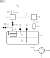
- In the following, the invention is described in more detail with reference to a figure.
Figure 1 shows an example of a device for continuously detecting refrigerant gas in water, comprising a vessel according to the invention. - The device 1 comprises a
vessel 2 having a main inlet 3 and a main outlet 4. The main inlet 3 is for supplyingwater 11 to thevessel 2 and the main outlet 4 for dischargingwater 10 from thevessel 2. A pump 5 connected to the main outlet 4 for adjusting the pressure in thevessel 2. A lower pressure is set in thevessel 2 than in the suppliedwater 11 so that possibly containingrefrigerant gas 12 separates from thewater 10. - In this example, an air-gas mixture containing air at a level of 30 mg/liter is supplied to the supplied
water 11 via agas inlet valve 18. Duringoperation 12 mg/liter is stripped-off. - According to the invention the devise comprises a
detector 6 for measuring the concentration ofrefrigerant gas 12 which is connected to thevessel 2, to which the gas released 8 from thewater 10 is fed from thevessel 2. - A
detector 6 with a sensor that detects 1 ppm refrigerant gas in air, it is enough if more than 10/1000000=0,00001 ml/liter of refrigerant is stripped off in thevessel 2 for thedetector 6 to detect when equilibrium is formed. If 250 of the refrigerant in the inlet is stripped in thevessel 2 the content must be 0,00004 ml/liter. Since the actual refrigerant density at normal temperature and pressure is about 5 mg/ml it means that the content must be 0,0002 mg/liter. In theory the detection level in this conditions are 0,2 microgram/liter. - For protection reasons a
float valve 21 can be connected betweenvessel 2 and thedetector 6. Via a gas return line 7 the gas flow exiting from therefrigerant detector 6 can return to thevessel 2. The gas pipe can be a metal pipe to increase the temperature and reduce the relative humidity. Agas buffer tank 14 is installed in the gas recovery line 7, to which air can be supplied and through which surplus gas can be blown off. Thegas 8 is returned to thevessel 2 via thegas buffer tank 14. Thegas 8 is used as stripper gas. - Inside the vessel 2 a ski bord 13 can be installed on which the
water 10 forms a relatively thin stream so that even small gas bubbles in thewater 10 can reach the surface. - During Operation water containing potential leaked gas is supplied to a
vessel 2 through the main inlet 3. Inside the vessel the pressure is lower than in the suppliedwater 11 system causing thegas 12 to separate from thewater 10. To improve the amount ofgas 12 that leaves thewater 10,air 15 is supplied to the water stream through avalve 18. - The
gas 12, which mainly contains air and potential leaked refrigerant gas, that is released from the water is sucked from thevessel 2 to arefrigerant detector 6 were the concentration of refrigerant gas is measured. - The outlet gas flow from the
refrigerant detector 6 is returned to the tank and used as the stripper gas. Only the surplus of gasses will leave the system. That surplus is formed by all gases that enters the system with the water subtracted with the gasses that leaves the system with the water again. - Also a small leak will in this way accumulate in the tank until an equilibrium is formed between the incoming stripped gasses and the outlet surplus gas. If this equilibrium is formed at a concentration above the detection level of the detector the leak will be detected. In this way a gas detector of more standard type and with a low cost can be used.
- The strategic positioning of sample points in the main water flow is of high importance. In one embodiment of the invention, sampling lances are provided at a plurality of sampling points to be located at natural and/or designed high points of the heat exchangers. This is to maximize the likelihood that refrigerant released in the water will be captured. During operation it is also possible to alternate automatically or by command from operator between different sample points, e.g. inlet and other points. For this purpose, each sample point has a shut off valve.
- With the invention it is possible to continuously and automatically operate a refrigerant detecting. The invention uses air as stripping gas. Additionally, the invention allows the use of a cost-effective sensor without an expensive spectrophotometer. The invention aims to detect both bubbles and a re-presentative flow with any gas dissolved therein. Thus, the invention does not indicate the content in the water as a result, but rather the size of the leak. The invention is designed to detect gas in bubble form as well as in dissolved form.
Claims (8)
- A device (1) for continuously detecting refrigerant in water (10), comprising a vessel (2) having a main inlet (3) for supplying water (11) to the vessel (2), a gas buffer (14) to supply air (15) to the vessel (2), a main outlet (4) for discharging water (10) from the vessel (2), a pump (5) connected to the main outlet (4) for adjusting the pressure in the vessel (2), wherein a lower pressure is set in the vessel (2) than in the supplied water (11) so that possibly containing refrigerant gas (12) separates from the water (10), characterized in that a refrigerant detector (6) for measuring the concentration of refrigerant gas (12) is connected to the vessel (2), to which the gas released (8) from the water (10) is fed from the vessel (2), and the gas is returned to the vessel (2) in a gas return line (7) via the gas buffer (14) as stripper gas.
- A device (1) according to claim 1, wherein the water (10) for continuous detection of refrigerant is sampled at several locations in the main water stream to be tested, placed at some natural and/or planned high points of the heat exchangers.
- The device (1) according to claim 1 or 2, wherein the water for the continuous detections of refrigerant gas is sampled by sample lances.
- The device (1) according to one of the claims 1 to 3, wherein a ski board (13) is inside the vessel (2) on which the water (10) forms a relatively thin stream so that even small gas bubbles in the water (10) can reach the surface.
- A method for continuously detecting refrigerant in water (10), wherein the water possibly containing refrigerant gas is fed into a vessel (2) via a water inlet (3), and air (15) is supplied to the vessel (2) via a gas buffer (14), and the water (10) is pumped out of the vessel via a pump (5), wherein a lower pressure is set in the vessel (2) than in the supplied water (11), so that possibly containing refrigerant gas separates from the water,
characterized in that the gas released (12) from the water (10) is fed from the vessel (2) to a refrigerant detector (6), where the concentration of the refrigerant gas is measured, and the gas is returned to the vessel (2) in a gas return line (7) via the gas buffer (14) as stripper gas. - A method according to claim 5, wherein the water (10) for the continuous detections of refrigerant gas is sampled at several locations in the main water stream to be tested, to be placed at some natural and/or planned high points of the heat exchangers.
- The method according to claim 5 or 6, wherein the water (10) for the continuous detections of refrigerant gas is sampled by sample lances.
- The method according to one of the claims 5 to 7, wherein there is a ski board (13) inside the vessel on which the water (10) forms a relatively thin stream so that even small gas bubbles in the water (10) can reach the surface.
Applications Claiming Priority (1)
| Application Number | Priority Date | Filing Date | Title |
|---|---|---|---|
| GB2219805.5A GB2625820B (en) | 2022-12-29 | 2022-12-29 | Detection system for refrigerant in water |
Publications (3)
| Publication Number | Publication Date |
|---|---|
| EP4394377A1 true EP4394377A1 (en) | 2024-07-03 |
| EP4394377B1 EP4394377B1 (en) | 2026-02-25 |
| EP4394377C0 EP4394377C0 (en) | 2026-02-25 |
Family
ID=85174553
Family Applications (1)
| Application Number | Title | Priority Date | Filing Date |
|---|---|---|---|
| EP23212413.1A Active EP4394377B1 (en) | 2022-12-29 | 2023-11-27 | Detection system for refrigerant in water |
Country Status (4)
| Country | Link |
|---|---|
| US (1) | US20240219087A1 (en) |
| EP (1) | EP4394377B1 (en) |
| JP (1) | JP2024095990A (en) |
| GB (1) | GB2625820B (en) |
Citations (2)
| Publication number | Priority date | Publication date | Assignee | Title |
|---|---|---|---|---|
| US5357781A (en) * | 1993-01-22 | 1994-10-25 | Sentech Corporation | Method and apparatus for sampling and detecting gases in a fluid |
| US20200318887A1 (en) * | 2018-01-12 | 2020-10-08 | Mitsubishi Electric Corporation | Air-conditioning apparatus |
Family Cites Families (9)
| Publication number | Priority date | Publication date | Assignee | Title |
|---|---|---|---|---|
| JPH0415282Y2 (en) * | 1988-05-06 | 1992-04-07 | ||
| US5693538A (en) * | 1995-08-31 | 1997-12-02 | Olin Corporation | System and method for monitoring volatile species in liquids |
| JPH11314085A (en) * | 1998-05-07 | 1999-11-16 | Kurita Water Ind Ltd | Organic matter-containing water treatment equipment |
| JP4820774B2 (en) * | 2007-04-20 | 2011-11-24 | 山陽電子工業株式会社 | Dissolved oxygen remover |
| JP2013137142A (en) * | 2011-12-28 | 2013-07-11 | Miura Co Ltd | Ice storing type cold water producing device |
| CN104807251B (en) * | 2015-05-20 | 2017-03-22 | 广东志高暖通设备股份有限公司 | Air cooling heat pump module water machine |
| WO2018166776A1 (en) * | 2017-03-17 | 2018-09-20 | Tata Steel Nederland Technology B.V. | Lance for a gas analysis system |
| JP2022162184A (en) * | 2021-04-12 | 2022-10-24 | パナソニックIpマネジメント株式会社 | Heat medium circulation system |
| MX2024008169A (en) * | 2021-12-30 | 2024-07-15 | Goodman Mfg Company L P | System with leak detection for detecting refrigerant leak. |
-
2022
- 2022-12-29 GB GB2219805.5A patent/GB2625820B/en active Active
-
2023
- 2023-11-27 EP EP23212413.1A patent/EP4394377B1/en active Active
- 2023-11-28 JP JP2023200318A patent/JP2024095990A/en active Pending
- 2023-12-09 US US18/534,612 patent/US20240219087A1/en active Pending
Patent Citations (2)
| Publication number | Priority date | Publication date | Assignee | Title |
|---|---|---|---|---|
| US5357781A (en) * | 1993-01-22 | 1994-10-25 | Sentech Corporation | Method and apparatus for sampling and detecting gases in a fluid |
| US20200318887A1 (en) * | 2018-01-12 | 2020-10-08 | Mitsubishi Electric Corporation | Air-conditioning apparatus |
Also Published As
| Publication number | Publication date |
|---|---|
| GB2625820B (en) | 2025-02-05 |
| EP4394377B1 (en) | 2026-02-25 |
| GB202219805D0 (en) | 2023-02-15 |
| GB2625820A (en) | 2024-07-03 |
| EP4394377C0 (en) | 2026-02-25 |
| JP2024095990A (en) | 2024-07-11 |
| US20240219087A1 (en) | 2024-07-04 |
Similar Documents
| Publication | Publication Date | Title |
|---|---|---|
| US8931330B2 (en) | Method and device for detecting leaks in an underground liquid pipe, particularly a water pipe | |
| US5398543A (en) | Method and apparatus for detection of vacuum leak | |
| US11365113B2 (en) | Method and apparatus for limiting acidic corrosion and contamination in fuel delivery systems | |
| US8752412B2 (en) | Sniffing leak detector | |
| US9784650B1 (en) | Sewer gas sampling and analyzing devices and methods | |
| US20250044214A1 (en) | Fuel/water separator probe | |
| US20240219087A1 (en) | Detection system for refrigerant in water | |
| EP4323689A1 (en) | A method of preparing a system for a maintenance operation | |
| US20220120771A1 (en) | On-line measurement for emitted aerosol precursors from industrial sources | |
| JP7457825B2 (en) | Ion analysis device and fuel cell evaluation system | |
| US11703419B2 (en) | Condensate discharging system for an exhaust-gas measuring device | |
| US20250271290A1 (en) | Low level water sensor and method of use | |
| CN211697762U (en) | Oil field production water on-line monitoring device | |
| CN100368808C (en) | Method and device for improving Karl Fischer water content determination | |
| CN113514615A (en) | System and method for gas path water inlet identification and water drainage of pump-suction type gas detector | |
| JP2003075344A (en) | Turbidity sensor | |
| GB2345134A (en) | Gas sampling and detecting system | |
| JP2005076070A (en) | Method for estimating corrosion of underground tank, method for preventing corrosion of underground tank, device for estimating corrosion of underground tank, and device for preventing corrosion of underground tank | |
| CN222419970U (en) | Auxiliary container for waste liquid discharged from flame photometer | |
| CN220154268U (en) | Online analyzer for formaldehyde in ambient air | |
| EP3935007A1 (en) | Method and apparatus for limiting acidic corrosion and contamination in fuel delivery systems | |
| CN221743835U (en) | Movable automatic water cutting device | |
| KR100241142B1 (en) | An automatic sample extraction apparatus using air ejector | |
| CN211202262U (en) | High-pressure pump detector | |
| CN120800670A (en) | Hydrogen leakage detection device and detection method |
Legal Events
| Date | Code | Title | Description |
|---|---|---|---|
| PUAI | Public reference made under article 153(3) epc to a published international application that has entered the european phase |
Free format text: ORIGINAL CODE: 0009012 |
|
| STAA | Information on the status of an ep patent application or granted ep patent |
Free format text: STATUS: THE APPLICATION HAS BEEN PUBLISHED |
|
| AK | Designated contracting states |
Kind code of ref document: A1 Designated state(s): AL AT BE BG CH CY CZ DE DK EE ES FI FR GB GR HR HU IE IS IT LI LT LU LV MC ME MK MT NL NO PL PT RO RS SE SI SK SM TR |
|
| STAA | Information on the status of an ep patent application or granted ep patent |
Free format text: STATUS: REQUEST FOR EXAMINATION WAS MADE |
|
| 17P | Request for examination filed |
Effective date: 20241003 |
|
| RBV | Designated contracting states (corrected) |
Designated state(s): AL AT BE BG CH CY CZ DE DK EE ES FI FR GB GR HR HU IE IS IT LI LT LU LV MC ME MK MT NL NO PL PT RO RS SE SI SK SM TR |
|
| GRAP | Despatch of communication of intention to grant a patent |
Free format text: ORIGINAL CODE: EPIDOSNIGR1 |
|
| STAA | Information on the status of an ep patent application or granted ep patent |
Free format text: STATUS: GRANT OF PATENT IS INTENDED |
|
| INTG | Intention to grant announced |
Effective date: 20251010 |
|
| RIC1 | Information provided on ipc code assigned before grant |
Ipc: G01N 33/18 20060101AFI20251003BHEP Ipc: F25B 49/00 20060101ALI20251003BHEP Ipc: F25B 41/00 20210101ALI20251003BHEP |
|
| GRAS | Grant fee paid |
Free format text: ORIGINAL CODE: EPIDOSNIGR3 |
|
| GRAA | (expected) grant |
Free format text: ORIGINAL CODE: 0009210 |
|
| STAA | Information on the status of an ep patent application or granted ep patent |
Free format text: STATUS: THE PATENT HAS BEEN GRANTED |
|
| AK | Designated contracting states |
Kind code of ref document: B1 Designated state(s): AL AT BE BG CH CY CZ DE DK EE ES FI FR GB GR HR HU IE IS IT LI LT LU LV MC ME MK MT NL NO PL PT RO RS SE SI SK SM TR |
|
| REG | Reference to a national code |
Ref country code: CH Ref legal event code: F10 Free format text: ST27 STATUS EVENT CODE: U-0-0-F10-F00 (AS PROVIDED BY THE NATIONAL OFFICE) Effective date: 20260225 Ref country code: GB Ref legal event code: FG4D |
|
| REG | Reference to a national code |
Ref country code: DE Ref legal event code: R096 Ref document number: 602023012564 Country of ref document: DE |
|
| REG | Reference to a national code |
Ref country code: IE Ref legal event code: FG4D |
|
| U01 | Request for unitary effect filed |
Effective date: 20260310 |
|
| U07 | Unitary effect registered |
Designated state(s): AT BE BG DE DK EE FI FR IT LT LU LV MT NL PT RO SE SI Effective date: 20260313 |