EP4394347A1 - Optical fiber monitoring - Google Patents
Optical fiber monitoring Download PDFInfo
- Publication number
- EP4394347A1 EP4394347A1 EP23217460.7A EP23217460A EP4394347A1 EP 4394347 A1 EP4394347 A1 EP 4394347A1 EP 23217460 A EP23217460 A EP 23217460A EP 4394347 A1 EP4394347 A1 EP 4394347A1
- Authority
- EP
- European Patent Office
- Prior art keywords
- optical
- optical fiber
- otdr
- monitoring apparatus
- splitter
- Prior art date
- Legal status (The legal status is an assumption and is not a legal conclusion. Google has not performed a legal analysis and makes no representation as to the accuracy of the status listed.)
- Pending
Links
Images











Classifications
-
- G—PHYSICS
- G01—MEASURING; TESTING
- G01M—TESTING STATIC OR DYNAMIC BALANCE OF MACHINES OR STRUCTURES; TESTING OF STRUCTURES OR APPARATUS, NOT OTHERWISE PROVIDED FOR
- G01M11/00—Testing of optical apparatus; Testing structures by optical methods not otherwise provided for
- G01M11/30—Testing of optical devices, constituted by fibre optics or optical waveguides
- G01M11/31—Testing of optical devices, constituted by fibre optics or optical waveguides with a light emitter and a light receiver being disposed at the same side of a fibre or waveguide end-face, e.g. reflectometers
- G01M11/3109—Reflectometers detecting the back-scattered light in the time-domain, e.g. OTDR
Definitions
- the OTDR may be optically connected to N optical fibers including the optical fiber to extract, from each optical fiber of the N optical fibers, information by analyzing signals returned from the N optical fibers to the N test port optical fiber outputs.
- the OTDR may be optically connected to N optical fibers including the optical fiber to compare, for the N optical fibers, N simultaneous test results to a reference test result to identify changes on at least one optical fiber under test of the N optical fibers.
- the optical fiber monitoring apparatus described above may further include an optical switch optically inserted between the OTDR and the 1 ⁇ N optical splitter.
- the OTDR may be a multi-wavelength OTDR.
- the apparatus may further include a multi-wavelength multiplexer/demultiplexer optically inserted between the OTDR and a plurality of 1 ⁇ N splitters including the 1 ⁇ N optical splitter.
- monitoring system 500 may include several OTDRs (e.g., eight OTDRs), from 502 to 504 that may operate simultaneously, thus reducing the test time. Measurements may be performed in parallel from the first optical fiber 506 to the last optical fiber 508.
- several OTDRs may be combined by sharing certain hardware and/or software components in order to reduce the price or the system footprint.
- this configuration provides for the addition of an additional measurement port with a relatively higher OTDR dynamic range than the N measurement ports from the 1-to-n splitter.
Landscapes
- Physics & Mathematics (AREA)
- Optics & Photonics (AREA)
- Chemical & Material Sciences (AREA)
- Analytical Chemistry (AREA)
- General Physics & Mathematics (AREA)
- Optical Communication System (AREA)
Abstract
Description
- A fiber optic cable may include one or more optical fibers that may be used to transmit light from a source to a destination. The optical fibers of the fiber optic cable may be referred to as fiber optic links. Fiber optic cables may represent a network element of a fiber optic network. In this regard, other types of network elements may include optical connectors, optical splices, optical couplers, and optical switches. Testing of a fiber optic link may be performed, for example, for installation and other purposes. An optical time domain reflectometer (OTDR) may be a reference tool that may be utilized for monitoring fiber optic links. Monitoring systems may need to be able to automatically perform tests on several optical fibers when there may be several optical fibers that are to be tested per cable and/or several cables that are to be tested. Connecting the OTDR to different cables may be performed by utilizing optical switches that sequentially connect the OTDR to the different optical fibers under test. Adding active components (e.g., optical switches) may add complexity and cost to the monitoring solution.
- Features of the present disclosure may be illustrated by way of examples shown in the following figures. In the following figures, like numerals indicate like elements, in which:
-
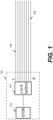
Figure 1 illustrates an optical fiber monitoring apparatus, according to an example of the present disclosure; -
Figure 2A illustrates testing of multiple optical fibers by utilizing an OTDR, according to an example of the present disclosure; -
Figure 2B illustrates testing of multiple optical fibers by utilizing an OTDR, according to an example of the present disclosure; -
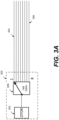
Figure 3A illustrates automatic testing and/or monitoring of a plurality of optical fibers using optical switches, according to an example of the present disclosure; -
Figure 3B illustrates a switching sequence, according to an example of the present disclosure; -
Figure 4 illustrates utilization of an optical multiplexer/demultiplexer, according to an example of the present disclosure; -
Figure 5 illustrates testing of several optical fibers in parallel, according to an example of the present disclosure; -
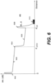
Figure 6 illustrates a reflectometric curve obtained with the test configuration ofFigure 1 , according to an example of the present disclosure; -
Figure 7 illustrates another example of an optical fiber monitoring apparatus that addresses the technical challenges discussed with respect toFigure 6 by inserting sections of optical fibers of different lengths between an optical splitter and optical fibers under test, according to an example of the present disclosure; -
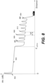
Figure 8 illustrates an example of an OTDR trace obtained with the configuration ofFigure 7 , according to an example of the present disclosure; -
Figure 9 illustrates operation of the optical fiber monitoring apparatus ofFigure 1 , according to an example of the present disclosure. -
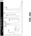
Figure 10A illustrates an example of an OTDR trace based on the configuration ofFigure 9 , according to an example of the present disclosure; -
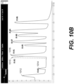
Figure 10B illustrates an example where one of the optical fiber endings in a reflection peak is cut or has a relatively strong attenuation, according to an example of the present disclosure; -
Figure 11 illustrates a block diagram of another example of the optical fiber monitoring apparatus ofFigure 1 , according to an example of the present disclosure; -
Figure 12 illustrates implementation of planar lightwave circuit (PLC) technology that utilizes waveguides fabricated by lithography on a silica glass substrate, according to an example of the present disclosure; -
Figure 13 illustrates implementation of another splitter technology denoted fused biconical taper (FBT), according to an example of the present disclosure; -
Figure 14 illustrates another example of the optical fiber monitoring apparatus ofFigure 1 that combines the use of two splitters and a Mux/deMux, according to an example of the present disclosure; -
Figure 15 illustrates utilization of an active component and passive components, according to an example of the present disclosure; -
Figure 16 illustrates the use of multi-channel OTDRs that provide for the simultaneous testing of several optical fibers, according to an example of the present disclosure; -
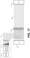
Figure 17 illustrates testing of a network under traffic, according to an example of the present disclosure; -
Figure 18 illustrates removal of an overlength optical fiber, according to an example of the present disclosure; -
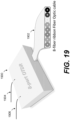
Figure 19 illustrates implementation of a reflectometric probe with outputs on an optical fiber ribbon, according to an example of the present disclosure; -
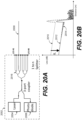
Figures 20A and 20B illustrate another example of the optical fiber monitoring apparatus where a single optical fiber may be connected to one of the N outputs, and an associated trace, according to an example of the present disclosure; -
Figures 21A and 21B illustrate another example of the optical fiber monitoring apparatus that provides full OTDR performance by using a 4-port optical coupler, according to an example of the present disclosure; -
Figure 22 illustrates another example of the optical fiber monitoring apparatus where an additional port may be used in combination with N ports connected to an optical splitter, according to an example of the present disclosure; -
Figures 23A and 23B illustrate operation of the optical fiber monitoring apparatus ofFigures 21A, 21B , and22 , according to an example of the present disclosure; and -
Figure 24 illustrates an example of an arrangement of optical fiber monitoring apparatus output connectors which include N parallel test outputs and a full specification OTDR output, according to an example of the present disclosure. - For simplicity and illustrative purposes, the present disclosure is described by referring mainly to examples thereof. In the following description, details may be set forth in order to provide an understanding of the present disclosure. It will be readily apparent however, that the present disclosure may be practiced without limitation to these details. In other instances, some methods and structures have not been described in detail so as not to unnecessarily obscure the present disclosure.
- Throughout the present disclosure, the terms "a" and "an" may be intended to denote at least one of a particular element. As used herein, the term "includes" means includes but not limited to, the term "including" means including but not limited to. The term "based on" means based at least in part on.
- According to examples disclosed herein, an optical fiber monitoring apparatus may include an optical time domain reflectometer (OTDR), and a 1 × N optical splitter that is optically connected to the OTDR. For N being greater than one, the 1 × N optical splitter may include N test port optical fiber outputs. Further, each test port optical fiber output may be optically connectable to an optical fiber to optically connect the optical fiber to the OTDR.
- For the optical fiber monitoring apparatus described above, the OTDR may be optically connected to N optical fibers including the optical fiber to extract, from each optical fiber of the N optical fibers, information by analyzing signals returned from the N optical fibers to the N test port optical fiber outputs.
- For the optical fiber monitoring apparatus described above, the OTDR may be optically connected to N optical fibers including the optical fiber to compare, for the N optical fibers, N simultaneous test results to a reference test result to identify changes on at least one optical fiber under test of the N optical fibers.
- The optical fiber monitoring apparatus described above may further include an optical switch optically inserted between the OTDR and the 1 × N optical splitter.
- The optical fiber monitoring apparatus described above may further include N optical fibers of different lengths optically inserted between the N test port optical fiber outputs and N optical fibers including the optical fiber, wherein the N optical fibers may be optically connected to the N test port optical fiber outputs.
- The optical fiber monitoring apparatus described above may further include N antennas connected to N optical fibers including the optical fiber, where the N optical fibers may be optically connected to the N test port optical fiber outputs.
- For the optical fiber monitoring apparatus described above, the OTDR may be a multi-wavelength OTDR. In this regard, the apparatus may further include a multi-wavelength multiplexer/demultiplexer optically inserted between the OTDR and a plurality of 1 × N splitters including the 1 × N optical splitter.
- For the optical fiber monitoring apparatus described above, the OTDR may be a simultaneous multi-channel OTDR. In this regard, the apparatus may further include a plurality of 1 × N splitters including the 1 × N optical splitter.
- For the optical fiber monitoring apparatus described above, the OTDR may operate at a different wavelength than a traffic wavelength. In this regard, the apparatus may further include a wavelength dependent multiplexer to insert a test signal on the optical fiber.
- According to examples disclosed herein, an optical fiber monitoring apparatus may include an optical source, an optical receiver, and an optical coupler optically inserted between the optical source, the optical receiver, and a 1 × N optical splitter. For N greater than one, the 1 × N optical splitter may include N test port optical fiber outputs. Further, each test port optical fiber output may be optically connectable to an optical fiber to optically connect the optical fiber to the optical source and the optical receiver.
- For the optical fiber monitoring apparatus described above, the optical source may include a laser, and the optical receiver may include a photodiode.
- For the optical fiber monitoring apparatus described above, the optical coupler may be an M-port optical coupler. In this regard, the optical coupler may include an additional output connected to an additional measurement port. In one example, M may be equal to three.
- According to examples disclosed herein, an optical fiber monitoring apparatus may include an OTDR, and a 1 × N optical splitter that is optically connected to the OTDR to test at least one optical fiber of N optical fibers that are optically connected to the 1 × N optical splitter, where N is greater than one. The OTDR may be optically connected to the N optical fibers to extract, from each optical fiber of the N optical fibers, information by analyzing signals returned from the N optical fibers. The OTDR may be optically connected to the N optical fibers to compare, for the N optical fibers, N simultaneous test results to a reference test result to identify changes on at least one optical fiber under test of the N optical fibers. The optical fiber monitoring apparatus may further comprise an optical switch optically inserted between the OTDR and the 1 × N optical splitter. The OTDR may be a multi-wavelength OTDR or a simultaneous multi-channel OTDR.
-
Figure 2A illustrates testing of multiple optical fibers by utilizing an OTDR, according to an example of the present disclosure. Referring toFigure 2A , with respect to optical fiber sensing generally, testing of multiple optical fibers using an OTDR may require successive connections of the OTDR to each of the optical fibers. As illustrated inFigure 2A , an operator may connect an OTDR onnear end 200 of a firstoptical fiber 202, then successively disconnect at 204, and then reconnect at 206 on the next optical fiber until having tested all of the optical fibers up to the last four. -
Figure 2B illustrates testing of multiple optical fibers by utilizing an OTDR, according to an example of the present disclosure. Referring toFigure 2B , with respect to testing of eight optical fibers, the duration of a test may be the sum ofmeasurement periods 208 andtransition periods 210 between two successive OTDR tests. For such a test, the manual switching may be time consuming and impact the total duration of the test of the eight optical fibers, thus making the measurement dependent on capabilities of the user that will perform the manipulation of the optical fibers. In addition, a test with manual switching may be acceptable for a single or a few optical fibers, but may not be practical for optical cable monitoring solutions due to the relatively large number of optical fibers that may need to be tested. -
Figure 3A illustrates automatic testing and/or monitoring of a plurality of optical fibers using optical switches, according to an example of the present disclosure. Referring toFigure 3A , for the automatic testing and/or monitoring performed at 300,OTDR 302 may be connected to different optical fibers from the firstoptical fiber 304 to the lastoptical fiber 306 using a 1x8optical switch 308. -
Figure 3B illustrates a switching sequence, according to an example of the present disclosure. The switching sequence illustrated inFigure 3B shows the sequence between test phases (e.g., 310, 312) and transition phases 314. Switching may be performed automatically without manipulation of optical connectors by a user, and may thus be relatively faster and eliminate the risk of damage and/or pollution of the connectors during handling. -
Figure 4 illustrates utilization of an optical multiplexer/demultiplexer (e.g., Mux/deMux 402), according to an example of the present disclosure. Referring toFigure 4 ,monitoring system 400 may integrate a multi-wavelength or a wavelength-tunable OTDR that allows measurements through the Mux/DeMux 402 using the wavelengths adapted to each channel of this component. In this regard, tests may be performed sequentially. A test wavelength ofOTDR 404 may be set to that ofoutput 1 of the Mux/DeMux 402 connected to the firstoptical fiber 406, then to the following optical fibers until the test of the lastoptical fiber 408 connected tooutput 8 of the Mux/DeMux 402. This solution may utilize a moresophisticated OTDR 404, where the transition time from one channel to the next may be potentially faster and more repeatable in terms of insertion loss. Additionally, time-division multiplexing (TDM) may utilize the Mux/DeMux 402, which may be a passive optical component. -
Figure 5 illustrates testing of several optical fibers in parallel, according to an example of the present disclosure. Referring toFigure 5 ,monitoring system 500 may include several OTDRs (e.g., eight OTDRs), from 502 to 504 that may operate simultaneously, thus reducing the test time. Measurements may be performed in parallel from the firstoptical fiber 506 to the lastoptical fiber 508. In this regard, several OTDRs may be combined by sharing certain hardware and/or software components in order to reduce the price or the system footprint. - The automatic monitoring solutions described in
Figures 2-5 may be relatively expensive, and technically challenging to implement. In this regard and in order to address the various technical challenges disclosed herein,Figure 1 illustrates an optical fiber monitoring apparatus (hereinafter "apparatus 100"), according to an example of the present disclosure. Referring toFigure 1 , for theapparatus 100, the number of optical fibers to be tested in parallel may be relatively small. ForFigure 1 , fiber optic cables may be connected to 5G antennas. Theapparatus 100 may include anOTDR 102 connected to optical fibers to be tested through an intermediate passiveoptical splitter 104. The passiveoptical splitter 104 may include a 1 × N optical splitter (e.g., N = 8) that may distribute power of theOTDR 102 on each of the optical fibers from 106 to 108. A measurement may be performed based on eight OTDR tests corresponding to each optical fiber. Since theoptical fibers 106 to 108 include similar lengths, it may be technically challenging to differentiate the reflections present at the ends of each of the optical fibers under test. In this regard, the passive optical splitter 104 (which may replace an optical switch), may thus provide for cost reduction, power consumption reduction, and scanning time reduction. -
Figure 6 illustrates a reflectometric curve obtained with the test configuration ofFigure 1 , according to an example of the present disclosure. Referring toFigure 6 , the OTDR trace may begin withsection 600 upstream of the optical splitter located at the distance d splitter.Section 600 may be located between the reflection of aline start connector 602 andinsertion loss 604 corresponding to theoptical splitter 104.Section 606 may represent the combined result of the cumulative contributions of the eight optical fibers connected downstream of theoptical splitter 104.Section 606 may be located between the point corresponding to thehigh insertion loss 604 of the splitter and the cumulative reflections of the optical fiber ends 608, precedingnoise floor 610. If an optical fiber among the eight optical fibers is cut between the splitter distances and the optical fiber background, such a cut may be technically challenging to identify, particularly if the cut is relatively not reflective. -
Figure 7 illustrates another example of an opticalfiber monitoring apparatus 710 that addresses the technical challenges discussed with respect toFigure 6 by inserting sections of optical fibers of different lengths (e.g., 702 to 704) betweenoptical splitter 700 and optical fibers under test (e.g., 706 to 708), according to an example of the present disclosure. By adding to the length of the optical fibers under test (e.g., 706 to 708), thesesections 702 to 704 with different respective lengths may make it possible to shift the end of each optical fiber from each other optical fiber. -
Figure 8 illustrates an example of an OTDR trace obtained with the configuration ofFigure 7 , according to an example of the present disclosure. Referring toFigure 8 , the OTDR trace may begin withsection 800 upstream of the optical splitter located at the distance d splitter.Section 800 may be located betweenreflection 802 of the front end connector and the insertion loss located at the splitter location. For the distance between the optical splitter location d and the longestoptical fiber 804, the OTDR trace may represent the sum of the contributions of each optical fiber. Thus, the reflective event may correspond to theend # 1 of the firstoptical fiber 806. It may be thus possible to detect cuts in an optical fiber by the disappearance of the reflective event corresponding to its end. If the amplitude of the end reflection is known, it may be possible to estimate optical losses on the corresponding optical fiber by following the sum of the reflective peaks. In some cases however, the distance Δd between two adjacent reflective events (e.g., 808, 810) may be too small to be able to differentiate the events. - In some cases, dedicated reflectors may be connected to the end of the optical fibers to generate calibrated reflective signals which will be used as a reference to follow the attenuation of each optical fiber.
- With continued reference to
Figure 8 , the OTDR trace may vary according to factors such as the performance of the OTDR that is utilized, the configuration of the network under test, and the number N outputs of the 1 to N coupler. Thus, it may be possible to detect an excess loss or an optical fiber break using the end of optical fiber reflection as a reference. It may also be possible to locate faults at a distance based on the performance of the OTDR and the configuration of the network. -
Figure 9 illustrates operation of theapparatus 100, according to an example of the present disclosure. A network including optical fibers connected to various antenna types may be connected to afeeder cable 900 that is further connected to theapparatus 100. The location of thedifferent antennas 904 may make the coincidence of the appearance of the different optical fiber ends unlikely. Theapparatus 100 may utilize anOTDR 906 connected to theoptical splitter 908 that is in turn connected to the variousoptical fibers 1 to 8 of thefeeder cable 900. -
Figure 10A illustrates an example of an OTDR trace based on the configuration ofFigure 9 , according to an example of the present disclosure. Referring toFigure 10A , the different reflective peaks fromR # 1 toR # 8 may be visible on the OTDR trace. The firstreflective event 1020 may correspond to the insertion loss and reflection at the level of the optical splitter. The shortest optical fiber may be visible by the reflectiveevent R # 2 at 1022.Reflective events # 3 at 1000 and #1 at 1002 may correspond to a case where two optical fibers have similar lengths but not enough for the reflective peaks to be clearly separated from each other.Reflective peak # 6 at 1004 may correspond to the antenna farthest from the OTDR. -
Figure 10B illustrates an example where one of the optical fiber endings in a reflection peak is cut or has a relatively strong attenuation, according to an example of the present disclosure. Referring toFigure 10B , one of the optical fiber endings in a reflectionpeak R # 3 at 1010 may be cut or has a strong attenuation. The impact on the level of backscattering may not be visible, but the disappearance of the reflective peak at 1010 (e.g., dotted line event) may be visible. Theprevious events R # 3 at 1010 andR # 1 at 1016. -
Figure 11 illustrates a block diagram of another example of an optical fiber monitoring apparatus, according to an example of the present disclosure. Referring toFigure 11 , opticalfiber monitoring apparatus 1100 may include at least oneoptical source 1102, at least oneoptical reception system 1104, and a coupling system betweenblocks monitoring apparatus 1100 may includeoptical splitter 1106 whoseoptical fibers 1108 allow the optical connection for the optical fiber system under test. -
Figure 12 illustrates implementation of planar lightwave circuit (PLC) technology that utilizes waveguides fabricated by lithography on a silica glass substrate, according to an example of the present disclosure. Referring toFigure 12 , the optical fiber splitter may connect a singleoptical fiber 1200 to an 8-optical fiber ribbonoptical fiber 1204. The tree structure ofoptical waveguides 1202 illustrates the three-stage signal splitting geometry. PLC splitters may include different splitting ratio, where 1xN may include 1×4, 1×8, 1×16, 2×32, 2×64, etc. The couplers may be balanced, such that power may be divided equally at each separation of the waveguides (e.g., 50/50). -
Figure 13 illustrates implementation of another splitter technology denoted fused biconical taper (FBT), according to an example of the present disclosure. With respect toFigure 13 , the manufacturing process may include removing the coating layer of two optical fibers, and heating and stretching the assembly. The bringing together of the two optical fibers may promote the coupling of energy between the optical fibers. This structure may control the splitting ratio by controlling the length of the twist angle and optical fiber stretch. - For
Figure 13 , 2xN balanced splitters with two input optical fibers may proportionally divide the power of the optical signal. The example ofFigure 13 illustrates use of a 2 × 8splitter 1300. The OTDRs incorporate a 3-port optical coupling system to allow the signal from the source to be transmitted to the fiber under test, and to allow the return signal from the fiber under test to reach the receiver of the OTDR. Thefirst coupling stage 1302 may thus be used for a coupling system between the optical source (O.S) of OTDR connected to theoptical port 1304 and the OTDR optical receiver (O.R.) to be connected tooptical port 1306 . Theoptical coupling stage 1302 of the OTDR and the distribution splitter up to the multiple-fiber 1308 may be combined as shown in a single component. The optical source of the OTDR connected to theoptical port 1304 may be a low cost transmitter optical sub assembly type (TOSA) and the OTDR optical receiver connected tooptical port 1306 may be a receiver optical sub assembly (ROSA) type. In another example, integrated photonics technology platforms such as photonic integrated circuits may be utilized. - Hybrid combinations using several coupling technologies may make it possible to extend the capacity of the
apparatus 100, in particular the number of optical fibers monitored at the same time. Insertion losses of optical splitters may increase with the number of outputs. A 1 × 8 optical splitter may typically include an insertion loss of approximately 10dB at 1550nm, with another 10dB being added for a 1 × 64 optical splitter. The OTDR measurement dynamics may be consumed by this optical loss and the analysis of the trace beyond the optical splitter may become technically challenging. In this regard,Figure 14 illustrates another example of an optical fiber monitoring apparatus that combines the use of two 1 × 8splitters deMux 1402. A bi-OTDR 1404 capable of testing at two different wavelengths simultaneously may test via the Mux/DeMuX 1402 and each of the twooptical splitters 1 to 8 at 1400. In another example, thebi-OTDR 1404 may be replaced by a bi-wavelength OTDR which may alternately test each of the groups of eightoptical fibers 1408 connected to each of the 1 × 8 optical splitters. Alternatively, thebi-OTDR 1404 may be replaced by a multi-wavelength or tunable wavelength OTDR and the bi-wavelength Mux/DeMux may be replaced by a dense or coarse wavelength division multiplexer. -
Figure 15 illustrates utilization of an active component and passive components, according to an example of the present disclosure. With reference to the hybrid setup depicted inFigure 15 , the use of an active component 1500 (e.g., optical switch) is shown combined withpassive components optical switch 1500 may make it possible to sequentially test groups of 8optical fibers 1508 in parallel. -
Figure 16 illustrates the use of multi-channel OTDRs that provide for the simultaneous testing of several optical fibers, according to an example of the present disclosure. The use of multi-channel OTDRs may provide for the simultaneous testing of several optical fibers utilizing parallel-OTDRs. In this regard, opticalfiber monitoring apparatus 1600 may include a parallelmulti-channel OTDR 1606, each input/output of which may be connected through an optical fiber (e.g., 1608, 1610, and 1612) to an independent 1 × 8 splitter (e.g., 1602, etc.), thus multiplying the number ofoutputs 1604 which can be monitored simultaneously. -
Figure 17 illustrates testing of a network under traffic, according to an example of the present disclosure. Referring toFigure 17 , for the network under traffic (e.g., live-network),Tx 1700 andRx 1702 transmission equipment may operate at a wavelength different from the test wavelength ofOTDR 1704.Optical fibers 1712 andmultiplexers 1706 may make it possible to insert the optical test signal on theoptical cable 1708. In this regard, the solution based on the addition of overlengthoptical fiber 1710 may be used to avoid the coincidence of events of the different optical fiber ends. In the case of the antenna network monitoring example ofFigure 9 , the overlength optical fibers may be removed. -
Figure 18 illustrates removal of an overlength optical fiber, according to an example of the present disclosure. Referring toFigure 18 , in the case of the antenna network monitoring example ofFigure 9 , the overlength optical fibers may be removed. In this regard, 1 × 8splitter 1800 may be directly connected to the input/outputoptical fibers 1 to 8 via theoptical fibers 1802. Further,cable 1804 may be connected to the eightantennas 1806. -
Figure 19 illustrates implementation of a reflectometric probe with outputs on an optical fiber ribbon, according to an example of the present disclosure. With respect toFigure 19 , in another example, theapparatus 100 may be based on an OTDR system with a multi-optical fiber output and spontaneous acquisition on all of the connected optical fibers. For example, a standalone OTDR may be utilized with several optical measurement ports, based on the utilization of an on-board splitter. In this is regard,Figure 19 illustrates implementation of areflectometric probe 1900 with outputs on an 8-optical fiber ribbon 1902. Thereflectometric probe 1900 may be powered viacable 1904 and remote controlled via an Ethernet, USB or other equivalent type ofconnection 1906. Alternatively, a front-end ribbon cable connector may be utilized instead of an optical fiber ribbon cable to be spliced or connected. -
Figures 20A and 20B illustrate another example of the optical fiber monitoring apparatus where a single optical fiber may be connected to one of the N outputs, and an associated trace, according to an example of the present disclosure. Referring toFigure 20A , a singleoptical fiber 2000 may be connected to one of the N outputs ofmonitoring apparatus 2002. A 3-port coupling device (2 to 1) may be used to couple the OTDR laser 2004 (e.g., OTDR source) to the fiber 2000 (e.g., fiber under test) through the 1 ×N splitter 2016 and to couple the signal returned by thefiber 2000 back to the OTDR photodiode 2006 (e.g., OTDR receiver). The use of a 1 ×N splitter 2016 may allow for simultaneous OTDR testing on all of the connected optical fibers, and may also add a relatively high insertion loss (e.g., 10dB for a 1 × 8 splitter). The 1 × N splitter insertion loss may reduce power ofOTDR laser 2004 launched into theoptical fiber 2000 and reduce the optical power returned toOTDR photodiode 2006. This optical attenuation may relatively significantly reduce the measurement dynamics of the OTDR, unlike the configuration using an optical switch.OTDR trace 2010 shown in dotted line illustrates a trace without taking into account the splitter insertion loss.OTDR trace 2012 illustrates the trace when a 10dB loss impacts the OTDR dynamic range, including anoisy trace 2014. -
Figures 21A and 21B illustrate another example of opticalfiber monitoring apparatus 2102 that provides full OTDR performance by using a 4-port optical coupler, according to an example of the present disclosure. For example, opticalfiber monitoring apparatus 2102 ofFigures 21A and 21B may utilize a 4-portoptical coupler 2100 instead of a 3-port coupler. In some cases, 2-to-1 couplers such as the ones based on fused biconical taper (FBT) may be 2-to-2 couplers with one output not used. The 4-portoptical coupler 2100 which interconnects optical source 2120,receiver N splitter 2108 does not add insertion loss compared to a 3-port coupler. The opticalfiber monitoring apparatus 2102 may include anadditional output 2104 connected toadditional measurement port 2106 of theoptical coupler 2100.Additional measurement port 2106 may be thus directly connected to the OTDR port without being impacted by the insertion loss of 1 toN splitter 2108. Optical fiber under test 2110 (shown in dashed), which was previously connected to one of theN ports 2114, may be now connected (e.g., at 2112) to theadditional measurement port 2106. -
Figure 21B shows that an OTDR measurement of the optical fiber undertest 2112 connected to theadditional measurement port 2106 benefits from the full performance of the OTDR. Thetrace 2124 shown inFigure 21B represents the OTDR trace when the optical fiber undertest 2110 is connected to one of theN ports 2114. Thetrace 2116 shows the full OTDR trace when the sameoptical fiber 2112 is connected to theadditional measurement port 2106 and not impacted by theinsertion loss 2118 of the 1xN splitter. The additional measurement port 2106 (e.g., 4th port) of the 4-port (2 to 2)coupler 2100 may be connected to additional output 2104 (e.g., OTDR connector) with a longer optical fiber than the N-ports to avoid N-port reflectance impact. This single-optical fiber measurement function may have applications during construction, system set-up and also for troubleshooting and maintenance. - It may helpful to avoid using an additional OTDR during these different steps. This N + 1 port configuration may be utilized when the lengths of two or more optical fibers under test are very close and the respective reflection peaks are difficult to distinguish. The measurement of the additional optical port may facilitate measurement of the optical fiber lengths of optical fibers of similar lengths. With this higher dynamic range with an optical fiber connected to the additional port, the OTDR may also be configured to provide improved distance location accuracy, for example by using a narrower pulse width if available on the OTDR. In this example, the use of the N optical ports and the additional port may be exclusive so as not to be disturbed by the combination of signals returned by one or more optical fibers connected to the N ports.
- Thus, with respect to the 4-port optical ( 2 to 2) coupler between the OTDR and the 1-to-n splitter, this configuration provides for the addition of an additional measurement port with a relatively higher OTDR dynamic range than the N measurement ports from the 1-to-n splitter.
-
Figure 22 illustrates another example of the opticalfiber monitoring apparatus 2202 where anadditional port 2200 may be used in combination with N ports connected to an optical splitter, according to an example of the present disclosure. Referring toFigure 22 , theadditional port 2200 may be not the only one used, but may be used in combination with the N ports connected tooptical splitter 2206. In this regard,additional output 2200 of the reflectometric opticalfiber monitoring apparatus 2202 may be used while other optical fibers may be connected to theN ports 2204. With regards toFigure 22 , one fiber may be disconnect (e.g., fiber 2208) from one of the 1 × N splitter outputs (e.g., 2204) to theadditional port 2200. This may facilitate in the identification of one end of anoptical fiber 2208 with respect to other ends of optical fibers of similar lengths. -
Figures 23A and 23B illustrate operation of the opticalfiber monitoring apparatus Figure 23A , a reflective event of very low amplitude may be visible on the OTDR trace of the measurement performed on the eight output ports. The signal linked to the part situated inside the opticalfiber monitoring apparatus 2102 and in particular the 1 × 8 splitter may be represented by the dashedline 2300. When the optical fiber whose reflective peak at 2310 is disconnected for connection to the additional port, the amplitude of the end-of-optical fiber reflection 2304 increases strongly (e.g., dotted-line event) and can be located with improved precision, for example by using a narrower test pulse. The insertion loss of the 1 × N splitter is shown at 2302. - In the same manner,
Figure 23B illustrates a case of differentiating more precisely tworeflective elevations 2306 which may be superimposed between the presence of optical fibers of very similar lengths. When one of the optical fibers connected to N ports is switched to the additional port, thereflective peak 2308 associated with this optical fiber appears clearly (e.g., dotted-line event) and may be precisely characterized in distance. - The optical
fiber monitoring apparatus 2102 may thus associate an additional output offering a relatively higher dynamic range compared to the range available on the N outputs. In order to reduce the cost of the installed solution, a few optical fiber monitoring apparatus with this additional port may be used as an installation tool during a set-up phase (e.g., identification of the different optical fiber ends) and then replaced by the an optical fiber monitoring apparatus that does not offer this additional port. - The additional port may be used to check the quality and the intrinsic loss of any of the N+1 output connectors (e.g., if any) by connecting a simple optical fiber jumper between any of the N outputs and additional output. This solution may be based on measurement of the OTDR pulse rather than backscatter-based connector insertion loss measurement, and may provide more accurate and faster measurements. The additional port may be used as an additional monitoring port in addition to the N ports, particularly if one optical fiber link has a much higher link budget than the N fibers and requires a higher dynamic range OTDR measurement.
-
Figure 24 illustrates a possible arrangement of optical fiber monitoring apparatus output connectors which include N parallel test outputs and a full specification OTDR output, according to an example of the present disclosure. With reference toFigure 24 , the output connectors may include Nparallel test outputs 2400 and a fullspecification OTDR output 2406. Alternatively, other types of connectors, such as a ribbon N fiber cable or multi-core fibers may be utilized. - What has been described and illustrated herein is an example along with some of its variations. The terms, descriptions and figures used herein may be set forth by way of illustration only and may be not meant as limitations. Many variations may be possible within the spirit and scope of the subject matter, which is intended to be defined by the following claims -- and their equivalents -- in which all terms may be meant in their broadest reasonable sense unless otherwise indicated.
Claims (15)
- An optical fiber monitoring apparatus comprising:an optical time domain reflectometer, OTDR; anda 1 × N optical splitter that is optically connected to the OTDR,wherein N is greater than one,wherein the 1 × N optical splitter includes N test port optical fiber outputs, andwherein each test port optical fiber output is optically connectable to an optical fiber to optically connect the optical fiber to the OTDR.
- The optical fiber monitoring apparatus according to claim 1, wherein the OTDR is optically connected to N optical fibers including the optical fiber to extract, from each optical fiber of the N optical fibers, information by analyzing signals returned from the N optical fibers to the N test port optical fiber outputs.
- The optical fiber monitoring apparatus according to claim 1, wherein the OTDR is optically connected to N optical fibers including the optical fiber to compare, for the N optical fibers, N simultaneous test results to a reference test result to identify changes on at least one optical fiber under test of the N optical fibers.
- The optical fiber monitoring apparatus according to claim 1, further comprising:
an optical switch optically inserted between the OTDR and the 1 × N optical splitter. - The optical fiber monitoring apparatus according to claim 1, further comprising:
N optical fibers of different lengths optically inserted between the N test port optical fiber outputs and N optical fibers including the optical fiber, wherein the N optical fibers are optically connected to the N test port optical fiber outputs. - The optical fiber monitoring apparatus according to claim 1, further comprising:
N antennas connected to N optical fibers including the optical fiber, wherein the N optical fibers are optically connected to the N test port optical fiber outputs. - The optical fiber monitoring apparatus according to claim 1, wherein the OTDR is a multi-wavelength OTDR, further comprising:
a multi-wavelength multiplexer/demultiplexer optically inserted between the OTDR and a plurality of 1 × N splitters including the 1 × N optical splitter. - The optical fiber monitoring apparatus according to claim 1, wherein the OTDR is a simultaneous multi-channel OTDR, further comprising:
a plurality of 1 × N splitters including the 1 × N optical splitter. - The optical fiber monitoring apparatus according to claim 1, wherein the OTDR operates at a different wavelength than a traffic wavelength, further comprising:
a wavelength dependent multiplexer to insert a test signal on the optical fiber. - The optical fiber monitoring apparatus according to claim 1 further comprising:an OTDR optical source;an OTDR optical receiver; andan optical coupler optically inserted between the OTDR optical source, the OTDR optical receiver, and the 1xN optical splitterwherein each test port optical fiber output is optically connectable to a respective optical fiber to optically connect the optical fiber to the OTDR optical source and the OTDR optical receiver.
- The optical fiber monitoring apparatus according to claim 10, wherein the OTDR optical source includes a laser.
- The optical fiber monitoring apparatus according to claim 10, wherein the OTDR optical receiver includes a photodiode.
- The optical fiber monitoring apparatus according to claim 10, wherein the optical coupler is an M-port optical coupler.
- The optical fiber monitoring apparatus according to claim 13, wherein the optical coupler includes an additional output connected to an additional measurement port.
- The optical fiber monitoring apparatus according to claim 13, wherein M is equal to three.
Applications Claiming Priority (2)
| Application Number | Priority Date | Filing Date | Title |
|---|---|---|---|
| EP23305002 | 2023-01-02 | ||
| US18/121,478 US20240223274A1 (en) | 2023-01-02 | 2023-03-14 | Optical fiber monitoring |
Publications (1)
| Publication Number | Publication Date |
|---|---|
| EP4394347A1 true EP4394347A1 (en) | 2024-07-03 |
Family
ID=89164196
Family Applications (1)
| Application Number | Title | Priority Date | Filing Date |
|---|---|---|---|
| EP23217460.7A Pending EP4394347A1 (en) | 2023-01-02 | 2023-12-18 | Optical fiber monitoring |
Country Status (1)
| Country | Link |
|---|---|
| EP (1) | EP4394347A1 (en) |
Citations (3)
| Publication number | Priority date | Publication date | Assignee | Title |
|---|---|---|---|---|
| US9240855B1 (en) * | 2011-01-05 | 2016-01-19 | Google Inc. | Fiber diagnosis system for point-to-point optical access networks |
| US9435712B2 (en) * | 2014-12-29 | 2016-09-06 | Verizon Patent And Licensing Inc. | OTDR signal injection for multi-band optical power balancing |
| US20180019813A1 (en) * | 2012-09-19 | 2018-01-18 | Ciena Corporation | Raman amplifier system and method with integrated optical time domain reflectometer |
-
2023
- 2023-12-18 EP EP23217460.7A patent/EP4394347A1/en active Pending
Patent Citations (3)
| Publication number | Priority date | Publication date | Assignee | Title |
|---|---|---|---|---|
| US9240855B1 (en) * | 2011-01-05 | 2016-01-19 | Google Inc. | Fiber diagnosis system for point-to-point optical access networks |
| US20180019813A1 (en) * | 2012-09-19 | 2018-01-18 | Ciena Corporation | Raman amplifier system and method with integrated optical time domain reflectometer |
| US9435712B2 (en) * | 2014-12-29 | 2016-09-06 | Verizon Patent And Licensing Inc. | OTDR signal injection for multi-band optical power balancing |
Non-Patent Citations (1)
| Title |
|---|
| NAKAZAWA MASATAKA ET AL: "Nondestructive measurement of mode couplings along a multi-core fiber using a synchronous multi-channel OTDR", OPTICS EXPRESS, vol. 20, no. 11, 18 May 2012 (2012-05-18), US, pages 12530, XP093355157, ISSN: 1094-4087, DOI: 10.1364/OE.20.012530 * |
Similar Documents
| Publication | Publication Date | Title |
|---|---|---|
| US20240223274A1 (en) | Optical fiber monitoring | |
| CA2809318C (en) | Method and system for detecting fiber fault in passive optical network | |
| KR101657329B1 (en) | Method and apparatus for fault discovery in a passive optical network(pon) | |
| US6177985B1 (en) | Apparatus and method for testing optical fiber system components | |
| US8692984B2 (en) | Field tester for topologies utilizing array connectors and multi-wavelength field tester for topologies utilizing array connectors | |
| US6980287B2 (en) | System for testing an optical network using optical time-domain reflectometry (OTDR) | |
| US8891965B2 (en) | Method for automatic configuration of an optical network element | |
| CN102571199B (en) | A kind of fiber failure detection method and device | |
| EP2337240B1 (en) | Multichannel WDM-PON module with integrated OTDR function | |
| WO2012097554A1 (en) | Optical line terminal, passive optical network system and optical signal transmission method | |
| EP0622912B1 (en) | Optical signal transmission network | |
| US8014670B2 (en) | Method and apparatus for testing and monitoring data communications in the presence of a coupler in an optical communications network | |
| EP3528401A1 (en) | Single otdr measurement for a plurality of fibers | |
| CN100558013C (en) | Monitoring device and method for optical fiber network | |
| WO2013017302A1 (en) | A method and a system for physical layer monitoring in point to multipoint passive optical networks based on reflectometry systems | |
| KR20090124437A (en) | Fixed reflector for OTDR and light path monitoring device using the same | |
| KR20040024733A (en) | Supervisory system for WDM-PON fiber using optical circulator | |
| US12413299B2 (en) | High speed bidirectional test of dual-fiber link | |
| JPH06232817A (en) | Optical fiber transmitter and testing method for the same | |
| JP4383162B2 (en) | Optical branch line monitoring system | |
| JP4103999B2 (en) | Optical line loss measuring method and measuring apparatus | |
| CN219514082U (en) | Multi-wavelength optical time domain reflectometer capable of carrying out optical test | |
| CN103501196B (en) | For system and the unit equipment thereof of quality of optical fiber link on-line monitoring | |
| CN117713917A (en) | Optical fiber monitoring method, device, system, electronic equipment and storage medium | |
| WO2025021367A1 (en) | Apparatus and method for testing a fibre optic telecommunications network |
Legal Events
| Date | Code | Title | Description |
|---|---|---|---|
| STAA | Information on the status of an ep patent application or granted ep patent |
Free format text: STATUS: UNKNOWN |
|
| PUAI | Public reference made under article 153(3) epc to a published international application that has entered the european phase |
Free format text: ORIGINAL CODE: 0009012 |
|
| STAA | Information on the status of an ep patent application or granted ep patent |
Free format text: STATUS: THE APPLICATION HAS BEEN PUBLISHED |
|
| AK | Designated contracting states |
Kind code of ref document: A1 Designated state(s): AL AT BE BG CH CY CZ DE DK EE ES FI FR GB GR HR HU IE IS IT LI LT LU LV MC ME MK MT NL NO PL PT RO RS SE SI SK SM TR |
|
| STAA | Information on the status of an ep patent application or granted ep patent |
Free format text: STATUS: REQUEST FOR EXAMINATION WAS MADE |
|
| 17P | Request for examination filed |
Effective date: 20241219 |
|
| STAA | Information on the status of an ep patent application or granted ep patent |
Free format text: STATUS: EXAMINATION IS IN PROGRESS |
|
| 17Q | First examination report despatched |
Effective date: 20260123 |