EP4394342A1 - Pressure sensor - Google Patents
Pressure sensor Download PDFInfo
- Publication number
- EP4394342A1 EP4394342A1 EP22861022.6A EP22861022A EP4394342A1 EP 4394342 A1 EP4394342 A1 EP 4394342A1 EP 22861022 A EP22861022 A EP 22861022A EP 4394342 A1 EP4394342 A1 EP 4394342A1
- Authority
- EP
- European Patent Office
- Prior art keywords
- sensor
- longitudinal direction
- sensor chip
- bonding
- transverse direction
- Prior art date
- Legal status (The legal status is an assumption and is not a legal conclusion. Google has not performed a legal analysis and makes no representation as to the accuracy of the status listed.)
- Pending
Links
Images


Classifications
-
- G—PHYSICS
- G01—MEASURING; TESTING
- G01L—MEASURING FORCE, STRESS, TORQUE, WORK, MECHANICAL POWER, MECHANICAL EFFICIENCY, OR FLUID PRESSURE
- G01L9/00—Measuring steady of quasi-steady pressure of fluid or fluent solid material by electric or magnetic pressure-sensitive elements; Transmitting or indicating the displacement of mechanical pressure-sensitive elements, used to measure the steady or quasi-steady pressure of a fluid or fluent solid material, by electric or magnetic means
- G01L9/0041—Transmitting or indicating the displacement of flexible diaphragms
- G01L9/0042—Constructional details associated with semiconductive diaphragm sensors, e.g. etching, or constructional details of non-semiconductive diaphragms
- G01L9/0048—Details about the mounting of the diaphragm to its support or about the diaphragm edges, e.g. notches, round shapes for stress relief
-
- G—PHYSICS
- G01—MEASURING; TESTING
- G01L—MEASURING FORCE, STRESS, TORQUE, WORK, MECHANICAL POWER, MECHANICAL EFFICIENCY, OR FLUID PRESSURE
- G01L9/00—Measuring steady of quasi-steady pressure of fluid or fluent solid material by electric or magnetic pressure-sensitive elements; Transmitting or indicating the displacement of mechanical pressure-sensitive elements, used to measure the steady or quasi-steady pressure of a fluid or fluent solid material, by electric or magnetic means
- G01L9/0041—Transmitting or indicating the displacement of flexible diaphragms
- G01L9/0051—Transmitting or indicating the displacement of flexible diaphragms using variations in ohmic resistance
- G01L9/0052—Transmitting or indicating the displacement of flexible diaphragms using variations in ohmic resistance of piezoresistive elements
-
- G—PHYSICS
- G01—MEASURING; TESTING
- G01L—MEASURING FORCE, STRESS, TORQUE, WORK, MECHANICAL POWER, MECHANICAL EFFICIENCY, OR FLUID PRESSURE
- G01L19/00—Details of, or accessories for, apparatus for measuring steady or quasi-steady pressure of a fluent medium insofar as such details or accessories are not special to particular types of pressure gauges
- G01L19/0007—Fluidic connecting means
- G01L19/0023—Fluidic connecting means for flowthrough systems having a flexible pressure transmitting element
-
- G—PHYSICS
- G01—MEASURING; TESTING
- G01L—MEASURING FORCE, STRESS, TORQUE, WORK, MECHANICAL POWER, MECHANICAL EFFICIENCY, OR FLUID PRESSURE
- G01L19/00—Details of, or accessories for, apparatus for measuring steady or quasi-steady pressure of a fluent medium insofar as such details or accessories are not special to particular types of pressure gauges
- G01L19/04—Means for compensating for effects of changes of temperature, i.e. other than electric compensation
-
- G—PHYSICS
- G01—MEASURING; TESTING
- G01L—MEASURING FORCE, STRESS, TORQUE, WORK, MECHANICAL POWER, MECHANICAL EFFICIENCY, OR FLUID PRESSURE
- G01L19/00—Details of, or accessories for, apparatus for measuring steady or quasi-steady pressure of a fluent medium insofar as such details or accessories are not special to particular types of pressure gauges
- G01L19/14—Housings
- G01L19/147—Details about the mounting of the sensor to support or covering means
Definitions
- the present invention relates to a pressure sensor.
- the pressure sensor according to the disclosure is configured such that a deformation-restraining effect on a sensor chip by a cap member strongly acts along a longitudinal direction of a diaphragm portion and weakly acts in a transverse direction.
- the pressure sensor according to the disclosure has a configuration that is unlikely to deform in the longitudinal direction of the diaphragm portion and is likely to deform in the transverse direction.
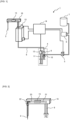
- FIG. 1 is a schematic configuration diagram showing a dispensing apparatus including a pressure sensor.
- a flow path system of a dispensing apparatus 1 includes a nozzle 2, a syringe pump 4, an electromagnetic valve 5, a gear pump 6, and a water tank 7, and the components are connected by a pipe 8.
- the syringe pump 4 includes a container 9, a plunger 10, a ball screw 11, and a drive motor 12.
- the dispensing apparatus 1 also includes an arm 16 (dispensing arm).
- the drive motor 12 is controlled by a control unit 14 in the same manner as a motor that drives a sample dispensing mechanism 13 and the like.
- FIG. 2 shows a state immediately after water 21 for syringe pressure transmission is suctioned into the pipe 8.
- the pipe 8 is filled with the water 21.
- a liquid 22 is introduced into the nozzle 2.
- Dividing air 23 is introduced between the water 21 and the liquid 22.
- the water 21 reaches a position of the pressure sensor 15.
- the sensor chip 31 is bonded to the terminal end portion of the opening portion 35 by the sensor chip bonding agent 36.
- a portion of the sensor chip 31 facing the opening portion 35 is the diaphragm portion 31a of the pressure sensor 15.
- the opening portion 35 and the diaphragm portion 31a are oval and have different dimensions in a longitudinal direction and a transverse direction.
- the shape of each of the opening portion 35 and the diaphragm portion 31a is not limited to the oval shape, and may be an elliptical shape, a rectangular shape with curved corner portions, or the like.
- the configuration of the embodiment is effective, for example, when it is desired to maximize a bonding area of the cap member 34 and to increase the sensor sensitivity.
- a purpose of increasing the bonding area of the cap member 34 is to ensure bonding strength and prevent resonance due to external vibration.
Landscapes
- Physics & Mathematics (AREA)
- General Physics & Mathematics (AREA)
- Chemical & Material Sciences (AREA)
- Analytical Chemistry (AREA)
- Measuring Fluid Pressure (AREA)
Abstract
Description
- The present invention relates to a pressure sensor.
- A pressure sensor using a piezoelectric element or the like is used in various fields.
- For example,
JP2018-146318A PTL 1 discloses that a pressure detection element of the semiconductor differential pressure sensor has a main surface fixed to a top portion of a first protruding portion by an adhesive in a state in which a second protruding portion is fitted into an opening portion, thereby obtaining a strong holding force and high positional accuracy of the pressure detection element, and discloses that the adhesive can be prevented from flowing into a first pressure introduction path and blockage of the first pressure introduction path can be prevented. -
JP2014-055868A -
- PTL 1:
JP2018-146318A - PTL 2:
JP2014-055868A - In order to improve pressure detection sensitivity of a pressure sensor using a strain sensor, it is effective to reduce a thickness of a diaphragm of a strain detection portion to increase strain against a pressure. However, as a drawback of thickness reduction, strength of the diaphragm decreases, and there is a concern that handling performance at the time of manufacturing may decrease, a chip fracture may occur, and the like.
- In order to solve this problem, it is effective to bond a cover member to a diaphragm for protection as described in
PTL 2. However, since rigidity of the diaphragm is also increased by bonding the cover member, the pressure detection sensitivity decreases, and there is room for improvement. - An object of the invention is to prevent breakage or the like of a diaphragm portion in a pressure sensor and to maintain pressure detection sensitivity.
- A pressure sensor according to the invention includes: a sensor housing having an opening portion having different dimensions in a longitudinal direction and a transverse direction; a sensor chip that is provided on the sensor housing in a manner of closing the opening portion and that forms a diaphragm portion; a strain gauge portion provided in the sensor chip; and a cap member bonded to the sensor chip by a cap bonding agent, in which among bonding surfaces of the cap bonding agent, bonding surfaces at both longitudinal direction end portions of the diaphragm portion each have a bonding area larger than that of bonding surfaces at both transverse direction end portions of the diaphragm portion.
- According to the invention, it is possible to prevent breakage or the like of a diaphragm portion in a pressure sensor and to maintain pressure detection sensitivity.
-
- [
FIG. 1] FIG. 1 is a schematic configuration diagram showing a dispensing apparatus including a pressure sensor. - [
FIG. 2] FIG. 2 is an enlarged view showing anarm 16 and the like inFIG. 1 . - [
FIG. 3A] FIG. 3A is an exploded perspective view showing a pressure sensor according to a first embodiment. - [
FIG. 3B] FIG. 3B is a vertical cross-sectional view showing the pressure sensor inFIG. 3A . - [
FIG. 4] FIG. 4 is an exploded perspective view showing a sensor chip portion of the pressure sensor inFIG. 3B . - [
FIG. 5A] FIG. 5A is a vertical cross-sectional view showing a deformed state (longitudinal direction) during use of a pressure sensor in the related art. - [
FIG. 5B] FIG. 5B is a vertical cross-sectional view of the pressure sensor inFIG. 5A as viewed along a transverse direction. - [
FIG. 6A] FIG. 6A is a vertical cross-sectional view showing a deformed state (longitudinal direction) during use of the pressure sensor according to the first embodiment. - [
FIG. 6B] FIG. 6B is a vertical cross-sectional view of the pressure sensor inFIG. 6A as viewed along the transverse direction. - [FIG. 7] FIG. 7 is a perspective view showing a sensor chip portion of a pressure sensor according to a second embodiment.
- [FIG. 8] FIG. 8 is a perspective view showing a sensor chip portion of a pressure sensor according to a third embodiment.
- [
FIG. 9] FIG. 9 is a top view showing a modification of a cap member of the pressure sensor. - [
FIG. 10] FIG. 10 is a top view showing another modification of the cap member of the pressure sensor. - The present disclosure relates to a pressure sensor, and particularly to a pressure sensor suitably used for detecting a pressure of a fluid, such as in a dispensing apparatus.
- The pressure sensor according to the disclosure is configured such that a deformation-restraining effect on a sensor chip by a cap member strongly acts along a longitudinal direction of a diaphragm portion and weakly acts in a transverse direction. In other words, the pressure sensor according to the disclosure has a configuration that is unlikely to deform in the longitudinal direction of the diaphragm portion and is likely to deform in the transverse direction.
- Hereinafter, embodiments in which the pressure sensor according to the disclosure is applied to a dispensing apparatus will be described.
-
FIG. 1 is a schematic configuration diagram showing a dispensing apparatus including a pressure sensor. - As shown in this figure, a flow path system of a dispensing
apparatus 1 includes anozzle 2, a syringe pump 4, anelectromagnetic valve 5, agear pump 6, and awater tank 7, and the components are connected by apipe 8. The syringe pump 4 includes acontainer 9, aplunger 10, aball screw 11, and adrive motor 12. The dispensingapparatus 1 also includes an arm 16 (dispensing arm). Thedrive motor 12 is controlled by acontrol unit 14 in the same manner as a motor that drives asample dispensing mechanism 13 and the like. - A
pressure sensor 15 is provided in thearm 16. Thearm 16 can perform a rotation operation and an up-down movement operation in order to move to a position where a liquid is suctioned or discharged. -
FIG. 2 is an enlarged view showing thearm 16 and the like inFIG. 1 . -
FIG. 2 shows a state immediately afterwater 21 for syringe pressure transmission is suctioned into thepipe 8. Thepipe 8 is filled with thewater 21. A liquid 22 is introduced into thenozzle 2. - Dividing
air 23 is introduced between thewater 21 and the liquid 22. Thewater 21 reaches a position of thepressure sensor 15. - By pressurizing the
water 21 by the syringe pump 4 (FIG. 1 ), a pressure can be transmitted to the liquid 22, and the liquid 22 can be suctioned or discharged from thenozzle 2. - When the liquid 22 is suctioned from the
nozzle 2, theplunger 10 in the syringe pump 4 is pulled while the electromagnetic valve 5 (FIG. 1 ) is in a closed state. On the other hand, when the liquid is discharged from thenozzle 2, theplunger 10 in the syringe pump 4 is pushed into thecontainer 9 while theelectromagnetic valve 5 is in a closed state. - When suctioning the liquid 22 such as a sample, the liquid 22 is suctioned after suctioning, by the
nozzle 2, the dividingair 23 for dividing such that the liquid 22 is not mixed with thewater 21 in thepipe 8. - After the discharge, the
nozzle 2 is washed. During the washing of thenozzle 2, thewater 21 in the flow path is pushed out simultaneously with application of washing water to an outer wall of thenozzle 2. In order to push out thewater 21 in thenozzle 2 during the washing, theelectromagnetic valve 5 is opened and a pressure of thegear pump 6 is used, so that thewater 21 can be sent out at a higher pressure than when pushing with the syringe pump 4. - The
pressure sensor 15 is provided on thepipe 8 in order to detect an abnormality such as clogging or air suction of thenozzle 2, which may occur during a dispensing operation. Thepressure sensor 15 monitors a pressure of thewater 21 and detects an abnormal pressure change. - The
pressure sensor 15 is preferably disposed at a position close to thenozzle 2 in order to reliably detect a pressure change in thenozzle 2. Therefore, in this figure, thepressure sensor 15 is provided in thearm 16. However, a position where thepressure sensor 15 is provided is not limited to the inside of thearm 16, and may be, for example, a side surface portion of thesample dispensing mechanism 13. - Next, a structure of the pressure sensor according to the disclosure will be described in more detail.
-
FIG. 3A is an exploded perspective view showing an example of the pressure sensor inFIG. 2 . -
FIG. 3B is a vertical cross-sectional view showing the pressure sensor inFIG. 3A . - As shown in
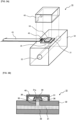
FIG. 3A , thepressure sensor 15 includes asensor chip 31, a cap member 34 (cover member), asensor housing 32, and acover 40. Aflow path 33 is formed inside thesensor housing 32. Screw portions (not shown) are provided at both end portions of theflow path 33, and theflow path 33 can be connected to thepipe 8 of thedispensing apparatus 1 via a joint. - An opening
portion 35 is provided in thesensor housing 32. The openingportion 35 communicates with theflow path 33. The openingportion 35 reaches an outer surface portion of thesensor housing 32. In other words, the openingportion 35 is configured to be branched from theflow path 33 toward the outer surface portion of thesensor housing 32 and reach the outer surface portion of thesensor housing 32. - The
sensor chip 31 is disposed at a terminal end portion of the openingportion 35 located in the outer surface portion of thesensor housing 32 in a manner of closing the openingportion 35. Thesensor chip 31 is bonded to thesensor housing 32 by a sensorchip bonding agent 36. In other words, a sensor chip bonding portion constituted by the sensorchip bonding agent 36 is provided between thesensor chip 31 and thesensor housing 32. Thecap member 34 is bonded to a surface of thesensor chip 31. In order to extract an output from thesensor chip 31, a printedcircuit board 45 is provided on thesensor housing 32. The printedcircuit board 45 is electrically connected to an electrode portion of thesensor chip 31 by abonding wire 46. The printedcircuit board 45 is a glass epoxy board, a flexible printed circuit board, or the like. - As shown in
FIG. 3B , thesensor chip 31 includes adiaphragm portion 31a that is a deformed portion thereof. The cap member 34 (cover member) that protects thediaphragm portion 31a is bonded to the surface of thesensor chip 31. Thecover 40 is provided on the outer surface portion of thesensor housing 32 to cover thesensor chip 31. Thecover 40 is fixed by adhesion, screwing, snap fitting, or the like. - The
diaphragm portion 31a is bent and deformed due to a pressure change of thewater 21 flowing through theflow path 33. Strain at that time is measured by thesensor chip 31, and thus the pressure of thewater 21 flowing in thesensor housing 32 is measured. The strain is measured by a strain gauge mounted on a surface of a central portion of thesensor chip 31. -
FIG. 4 is an exploded perspective view showing a sensor chip portion of the pressure sensor inFIG. 3B . - In this figure, the
sensor chip 31 is bonded to the terminal end portion of the openingportion 35 by the sensorchip bonding agent 36. A portion of thesensor chip 31 facing the openingportion 35 is thediaphragm portion 31a of thepressure sensor 15. The openingportion 35 and thediaphragm portion 31a are oval and have different dimensions in a longitudinal direction and a transverse direction. The shape of each of the openingportion 35 and thediaphragm portion 31a is not limited to the oval shape, and may be an elliptical shape, a rectangular shape with curved corner portions, or the like. - The
cap member 34 is bonded to the surface of thesensor chip 31 by a longitudinal direction both endvicinity bonding agent 37a and a transverse direction both endvicinity bonding agent 37b. In other words, between thesensor chip 31 and thecap member 34, a bonding portion (cap bonding portion) is provided, which includes the longitudinal direction both endvicinity bonding agent 37a and the transverse direction both endvicinity bonding agent 37b. Here, the vicinity of both ends may be rephrased as "both end portions". Therefore, the longitudinal direction both endvicinity bonding agent 37a is a bonding agent provided at both longitudinal direction end portions, and the transverse direction both endvicinity bonding agent 37b is a bonding agent provided at both transverse direction end portions. - A bonding surface of the longitudinal direction both end
vicinity bonding agent 37a is a longitudinal direction both endvicinity bonding surface 38a, and a bonding surface of the transverse direction both endvicinity bonding agent 37b is a transverse direction both endvicinity bonding surface 38b. Each of the longitudinal direction both endvicinity bonding agent 37a and the transverse direction both endvicinity bonding agent 37b is a thermosetting adhesive, a UV addition adhesive, a low-melting-point glass, a silver paste, or the like. Astrain gauge portion 31b for detecting strain is provided at a central portion of the surface of thesensor chip 31. - In the embodiment, bonding agents having the same storage elastic modulus are used as the longitudinal direction both end
vicinity bonding agent 37a and the transverse direction both endvicinity bonding agent 37b. - When the
diaphragm portion 31a receives a pressure from thewater 21 and is deformed, there is a difference in magnitude of strain in thediaphragm portion 31a between a longitudinal direction and a transverse direction of thestrain gauge portion 31b. - The
strain gauge portion 31b detects the strain in each of the longitudinal direction and the transverse direction, and outputs the difference therebetween. This is to offset temperature characteristics of thestrain gauge portion 31b. - Under a condition that sensor sensitivity is to be increased in the
pressure sensor 15 of such a type, it is important that an absolute value of the strain in thestrain gauge portion 31b is large and the difference in the strain between the longitudinal direction and the transverse direction is large. In order to increase the absolute value of the strain, it is effective to reduce a thickness of thesensor chip 31 to facilitate deformation. However, as a drawback of thickness reduction, strength of thesensor chip 31 decreases, and there is a concern that handling performance at the time of manufacturing may decrease, a chip fracture may occur, and the like. In the embodiment, in order to solve this problem, thecap member 34 is bonded to thesensor chip 31 to ensure strength. - However, as will be described later, when the
cap member 34 is bonded, rigidity of thediaphragm portion 31a also increases, the absolute value of the strain in thestrain gauge portion 31b decreases, and thus the sensor sensitivity decreases. - In order to solve this problem, among the bonding surfaces of the
cap member 34, a bonding area of the longitudinal direction both endvicinity bonding surface 38a is larger than that of the transverse direction both endvicinity bonding surface 38b. - Next, effects of the configuration in
FIG. 4 will be described with reference toFIGS. 5A to 6B . These figures each show a vertical cross-section passing through thestrain gauge portion 31b. -
FIG. 5A is a vertical cross-sectional view showing a deformed state (longitudinal direction) during use of a pressure sensor in the related art. -
FIG. 5B is a vertical cross-sectional view of the pressure sensor inFIG. 5A as viewed along the transverse direction. - Since no cap member is attached to the pressure sensor shown in these figures, the
sensor chip 31 is largely deformed upon receiving a pressure p from the water 21 (FIG. 3B ) . - When the
sensor chip 31 receives the pressure p and is deformed, tensile strain is generated in thestrain gauge portion 31b. Among the tensile strain, a longitudinal direction component is denoted by εx1 and a transverse direction component is denoted by εy1 in the figures. - The difference in dimension of the opening
portion 35 between the longitudinal direction and the transverse direction causes a difference in curvature of thestrain gauge portion 31b. Specifically, a curvature in the transverse direction is larger than that in the longitudinal direction, and εx1 < εy1 is satisfied when expressed in terms of a tensile strain magnitude relationship. As a sensor output, a difference εy1 - εx1 therebetween is output. - Due to such deformation, a portion of the
sensor chip 31 bonded by the sensorchip bonding agent 36 is displaced inward in each of the longitudinal direction and the transverse direction (in the figures, directions from the left and the right to the center) . Due to such displacement, the sensorchip bonding agent 36 receives a shear force from thesensor chip 31 and is in a state of shear deformation. -
FIG. 6A is a vertical cross-sectional view showing a deformed state (longitudinal direction) during use of the pressure sensor according to the embodiment. -
FIG. 6B is a vertical cross-sectional view of the pressure sensor inFIG. 6A as viewed along the transverse direction. - In the pressure sensor shown in these figures, since the
cap member 34 is attached, even when thesensor chip 31 receives the pressure p from the water 21 (FIG. 3B ), a deformation amount is smaller than that in the example of the related art shown inFIGS. 5A and 5B . - As shown in
FIGS. 6A and 6B , among the tensile strain, a longitudinal direction component is denoted by εx2, and a transverse direction component is denoted by εy2. In this case, the sensor output is εy2 - εx2. - In the embodiment, the tensile strain is restrained by rigidity of the
cap member 34. As shown inFIGS. 6A and 6B , the sensorchip bonding agent 36, the longitudinal direction both endvicinity bonding agent 37a, and the transverse direction both endvicinity bonding agent 37b receive a shear force from thesensor chip 31 and are in a state of shear deformation. Due to a deformation-restraining effect of thecap member 34, εx2 and εy2 are both smaller than those in the case where thecap member 34 is not attached. This causes a decrease in sensitivity due to the attachment of thecap member 34. - In order to prevent this decrease in sensitivity, in the embodiment, as shown in
FIG. 4 , the bonding area of the longitudinal direction both endvicinity bonding surface 38a is configured to be larger than that of the transverse direction both endvicinity bonding surface 38b. Accordingly, there is a difference in ease of shear deformation between the longitudinal direction both endvicinity bonding agent 37a and the transverse direction both endvicinity bonding agent 37b, and the transverse direction both endvicinity bonding agent 37b is more susceptible to shear deformation. That is, the deformation-restraining effect on thesensor chip 31 by thecap member 34 is relatively strong along the longitudinal direction and relatively weak along the transverse direction. As a result, the tensile strain εx2 of the longitudinal direction component decreases relatively largely whereas a decrease in the tensile strain εy2 of the transverse direction component is relatively small, and thus the sensor output εy2 - εx2, which is the difference therebetween, can be increased. - In this way, according to the configuration of the embodiment, the strength of the
sensor chip 31 can be ensured by thecap member 34, and the sensitivity of the pressure sensor can be maintained. - Although the bonding agents are disposed at positions that are linearly symmetrical with respect to the longitudinal direction and the transverse direction, the positions may not be line-symmetrical, and the same effects are obtained even when the bonding surfaces are changed within a range in which the magnitude relationship of the bonding areas is satisfied. The shape of the
cap member 34 is not limited to the shown shape. - In the above-described example, the description is made based on the magnitude of the bonding area, and as a configuration for obtaining the same effects, there is a configuration in which a long axis of the longitudinal direction both end
vicinity bonding surface 38a, that is, a length of the longitudinal direction both endvicinity bonding surface 38a close to the openingportion 35, is longer than a long axis of the transverse direction both endvicinity bonding surface 38b, that is, a length of the transverse direction both endvicinity bonding surface 38b close to the openingportion 35. This configuration also matches the configuration inFIG. 4 . In this case, as shown inFIG. 4 , it is assumed that short axes of the longitudinal direction both endvicinity bonding surface 38a and the transverse direction both endvicinity bonding surface 38b are substantially the same. - Alternatively, the short axes may be different. This is because the deformation-restraining effect by the
cap member 34 is affected by a dimension of the long axis more than the short axis among dimensions of the longitudinal direction both endvicinity bonding surface 38a and the transverse direction both endvicinity bonding surface 38b. - FIG. 7 is a perspective view showing a sensor chip portion of a pressure sensor according to a second embodiment.
- In a
pressure sensor 75 shown in this figure, thecap member 34 and thesensor chip 31 are bonded to each other by the longitudinal direction both endvicinity bonding agent 37a and a transverse direction both endvicinity bonding agent 77b having the same shapes as those in the first embodiment. - A feature of the embodiment is that a bonding agent having a smaller storage elastic modulus than that of the longitudinal direction both end
vicinity bonding agent 37a is selected as the transverse direction both endvicinity bonding agent 77b. Accordingly, as compared with the case where bonding agents having the same storage elastic modulus are used as in the first embodiment, the deformation-restraining effect on thesensor chip 31 by thecap member 34 in the transverse direction can be further reduced. Therefore, a decrease in the tensile strain εy2 of the transverse direction component is further reduced, and the sensor output εy2 - εx2 can be increased. - The configuration of the embodiment is effective, for example, when it is desired to maximize a bonding area of the
cap member 34 and to increase the sensor sensitivity. A purpose of increasing the bonding area of thecap member 34 is to ensure bonding strength and prevent resonance due to external vibration. - FIG. 8 is a perspective view showing a sensor chip portion of a pressure sensor according to a third embodiment.
- In a
pressure sensor 85 shown in this figure, unlike the first embodiment, thecap member 34 and thesensor chip 31 are bonded to each other by the longitudinal direction both endvicinity bonding agent 37a. No bonding agent is provided in the vicinity of both ends in the transverse direction. This corresponds to a case where the area (bonding area) of the transverse direction both endvicinity bonding surface 38b is 0 in the first embodiment. - Accordingly, the deformation-restraining effect on the
sensor chip 31 by thecap member 34 in the transverse direction is minimized. Therefore, a decrease in the tensile strain εy2 of the transverse direction component is minimized, and the sensor output εy2 - εx2 can be increased. Since the number of bonding portions is reduced, it is possible to shorten a step of applying an adhesive by a dispenser in a manufacturing step. -
FIG. 9 is a top view showing a modification of the cap member. - In this figure, one
rib 94 is provided in the longitudinal direction of thecap member 34. In other words, thecap member 34 includes onerib 94 provided along the longitudinal direction of the openingportion 35. - With this configuration, the rigidity of the
cap member 34 in the longitudinal direction can be increased, and deformation of thecap member 34 in the longitudinal direction can be restrained. Accordingly, a decrease in the tensile strain εx2 in the longitudinal direction can be restrained. -
FIG. 10 is a top view showing another modification of the cap member. - In this figure, three
ribs 94 are provided in the longitudinal direction of thecap member 34. - With this configuration, the rigidity of the
cap member 34 in the longitudinal direction can be further increased, and the deformation of thecap member 34 in the longitudinal direction can be further restrained. Accordingly, the decrease in the tensile strain εx2 in the longitudinal direction can be further restrained. - The invention is not limited to the above-described embodiments, and includes various modifications. The embodiments described above are described in detail to facilitate understanding of the invention, and the invention is not necessarily limited to those including all the described configurations. A part of the configuration of one embodiment can be replaced with the configuration of another embodiment. It is also possible to add the configuration of another embodiment to the configuration of a certain embodiment. A part of the configuration of each embodiment may be added to, deleted from, or replaced with another configuration.
-
- 1: dispensing apparatus
- 2: nozzle
- 4: syringe pump
- 5: electromagnetic valve
- 6: gear pump
- 7: water tank
- 8: pipe
- 9: container
- 10: plunger
- 11: ball screw
- 12: drive motor
- 13: sample dispensing mechanism
- 14: control unit
- 15: pressure sensor
- 16: arm
- 21: water
- 22: liquid
- 23: dividing air
- 31: sensor chip
- 31a: diaphragm portion
- 31b: strain gauge portion
- 32: sensor housing
- 33: flow path
- 34: cap member
- 35: opening portion
- 36: sensor chip bonding agent
- 37a: longitudinal direction both end vicinity bonding agent
- 37b: transverse direction both end vicinity bonding agent
- 38a: longitudinal direction both end vicinity bonding surface
- 38b: transverse direction both end vicinity bonding surface
- 40: cover
- 45: printed circuit board
- 46: bonding wire
Claims (5)
- A pressure sensor comprising:a sensor housing having an opening portion having different dimensions in a longitudinal direction and a transverse direction;a sensor chip that is provided on the sensor housing in a manner of closing the opening portion and that forms a diaphragm portion;a strain gauge portion provided in the sensor chip; anda cap member bonded to the sensor chip by a cap bonding agent, whereinamong bonding surfaces of the cap bonding agent, bonding surfaces at both longitudinal direction end portions of the diaphragm portion each have a bonding area larger than that of bonding surfaces at both transverse direction end portions of the diaphragm portion.
- A pressure sensor comprising:a sensor housing having an opening portion having different dimensions in a longitudinal direction and a transverse direction;a sensor chip that is provided on the sensor housing in a manner of closing the opening portion and that forms a diaphragm portion;a strain gauge portion provided in the sensor chip; anda cap member bonded to the sensor chip by a cap bonding agent, whereinamong bonding surfaces of the cap bonding agent, a long axis of bonding surfaces at both longitudinal direction end portions of the diaphragm portion is longer than a long axis of bonding surfaces at both transverse direction end portions of the diaphragm portion.
- A pressure sensor comprising:a sensor housing having an opening portion having different dimensions in a longitudinal direction and a transverse direction;a sensor chip that is provided on the sensor housing in a manner of closing the opening portion and that forms a diaphragm portion;a strain gauge portion provided in the sensor chip; anda cap member bonded to the sensor chip by a cap bonding agent, whereinthe cap member includes a rib provided along the longitudinal direction of the opening portion.
- The pressure sensor according to claim 1 or 2, wherein
among the cap bonding agent, the cap bonding agent at the both transverse direction end portions of the diaphragm portion has a smaller storage elastic modulus than the cap bonding agent at the both longitudinal direction end portions of the diaphragm portion. - The pressure sensor according to claim 1, wherein
the bonding area of the bonding surfaces at the both transverse direction end portions of the diaphragm portion is 0.
Applications Claiming Priority (2)
| Application Number | Priority Date | Filing Date | Title |
|---|---|---|---|
| JP2021137759A JP7546531B2 (en) | 2021-08-26 | 2021-08-26 | Pressure Sensors |
| PCT/JP2022/028419 WO2023026731A1 (en) | 2021-08-26 | 2022-07-22 | Pressure sensor |
Publications (2)
| Publication Number | Publication Date |
|---|---|
| EP4394342A1 true EP4394342A1 (en) | 2024-07-03 |
| EP4394342A4 EP4394342A4 (en) | 2025-10-22 |
Family
ID=85323029
Family Applications (1)
| Application Number | Title | Priority Date | Filing Date |
|---|---|---|---|
| EP22861022.6A Pending EP4394342A4 (en) | 2021-08-26 | 2022-07-22 | PRESSURE SENSOR |
Country Status (5)
| Country | Link |
|---|---|
| US (1) | US20240353278A1 (en) |
| EP (1) | EP4394342A4 (en) |
| JP (1) | JP7546531B2 (en) |
| CN (1) | CN117693671B (en) |
| WO (1) | WO2023026731A1 (en) |
Family Cites Families (18)
| Publication number | Priority date | Publication date | Assignee | Title |
|---|---|---|---|---|
| JPH02167441A (en) * | 1988-09-22 | 1990-06-27 | Terumo Corp | Throwaway pressure transducer and throwaway pressure transducing device |
| JPH02195941A (en) * | 1989-01-25 | 1990-08-02 | Yamatake Honeywell Co Ltd | Breathed air flow meter |
| JPH048917U (en) * | 1990-05-11 | 1992-01-27 | ||
| US5184107A (en) * | 1991-01-28 | 1993-02-02 | Honeywell, Inc. | Piezoresistive pressure transducer with a conductive elastomeric seal |
| JPH0862078A (en) * | 1994-08-24 | 1996-03-08 | Seiko Epson Corp | Pressure sensor and manufacturing method thereof |
| JP3592023B2 (en) * | 1997-03-04 | 2004-11-24 | 日本碍子株式会社 | Method for manufacturing functional film element |
| DE19830538A1 (en) * | 1998-07-08 | 2000-01-20 | Siemens Ag | Pressure sensor arrangement, in particular for pressure detection in an oil-loaded pressure area of a motor vehicle transmission |
| US6229190B1 (en) * | 1998-12-18 | 2001-05-08 | Maxim Integrated Products, Inc. | Compensated semiconductor pressure sensor |
| JP2001337103A (en) | 2000-05-26 | 2001-12-07 | Matsushita Electric Works Ltd | Semiconductor acceleration sensor |
| JP4569242B2 (en) * | 2004-09-22 | 2010-10-27 | パナソニック電工株式会社 | Physical quantity sensor |
| JP2014055868A (en) | 2012-09-13 | 2014-03-27 | Azbil Corp | Pressure sensor, manufacturing method therefor, and member bonding method |
| US9470593B2 (en) | 2013-09-12 | 2016-10-18 | Honeywell International Inc. | Media isolated pressure sensor |
| JP5975970B2 (en) * | 2013-11-20 | 2016-08-23 | 日立オートモティブシステムズ株式会社 | Pressure sensor |
| CN107110727B (en) * | 2014-10-07 | 2019-06-18 | 日立金属株式会社 | Pressure sensors and differential pressure sensors and mass flow control devices using them |
| DE102015116648A1 (en) * | 2015-10-01 | 2017-04-06 | Biotronik Se & Co. Kg | Implantable pressure sensor device |
| JP6253825B1 (en) * | 2017-03-03 | 2017-12-27 | 三菱電機株式会社 | Semiconductor differential pressure sensor |
| RU2761590C1 (en) | 2018-02-19 | 2021-12-10 | Реналсенс Лтд. | Sensor unit |
| DE102019216485A1 (en) | 2019-10-25 | 2021-04-29 | Raumedic Ag | Connector for a patient ventilation system |
-
2021
- 2021-08-26 JP JP2021137759A patent/JP7546531B2/en active Active
-
2022
- 2022-07-22 CN CN202280049139.8A patent/CN117693671B/en active Active
- 2022-07-22 WO PCT/JP2022/028419 patent/WO2023026731A1/en not_active Ceased
- 2022-07-22 EP EP22861022.6A patent/EP4394342A4/en active Pending
- 2022-07-22 US US18/291,964 patent/US20240353278A1/en active Pending
Also Published As
| Publication number | Publication date |
|---|---|
| CN117693671B (en) | 2026-06-12 |
| EP4394342A4 (en) | 2025-10-22 |
| WO2023026731A1 (en) | 2023-03-02 |
| US20240353278A1 (en) | 2024-10-24 |
| JP7546531B2 (en) | 2024-09-06 |
| JP2023031956A (en) | 2023-03-09 |
| CN117693671A (en) | 2024-03-12 |
Similar Documents
| Publication | Publication Date | Title |
|---|---|---|
| US8316725B2 (en) | Force sensor | |
| US8869623B2 (en) | Pressure sensor mounting structure | |
| EP1983324A2 (en) | Dual pressure sensor apparatus | |
| EP4339574A1 (en) | Pressure sensor module and dispensing device | |
| EP3623785A1 (en) | Force sensor with gap-controlled over-force protection | |
| US20100078447A1 (en) | Fluid product dispensing device | |
| EP3453320A1 (en) | Pressure pulse wave sensor, pulse wave detection device, and biological information measurement device | |
| US20240353278A1 (en) | Pressure Sensor | |
| EP4443126A1 (en) | Pressure sensor module and dispensing device having pressure sensor module | |
| EP3714779B1 (en) | Noninvasive blood pressure sensor | |
| EP3232516A1 (en) | Water-resistant electronic component | |
| EP3580541A1 (en) | Micrometer mechanical force interface | |
| WO2023233819A1 (en) | Pressure sensor | |
| US6612180B1 (en) | Dielectrically isolated plastic pressure transducer | |
| TWI646989B (en) | Valve, fluid control device and sphygmomanometer | |
| JP7592191B2 (en) | Pressure sensor and dispensing device | |
| US12366494B2 (en) | Gel-coupled pressure sensor device with interference-independent contact side for connection to an infusion hose | |
| JP2001033336A (en) | Pressure detector | |
| EP3831425A1 (en) | Connection member, injection device and pump casing equipped with connection member, and liquid verification method using connection member | |
| US12350662B2 (en) | Attachment method for microfluidic device | |
| JP2020071191A (en) | Dispenser | |
| WO2025088898A1 (en) | Fluid sensor module | |
| JP2018035733A (en) | Pump and robot hand |
Legal Events
| Date | Code | Title | Description |
|---|---|---|---|
| STAA | Information on the status of an ep patent application or granted ep patent |
Free format text: STATUS: THE INTERNATIONAL PUBLICATION HAS BEEN MADE |
|
| PUAI | Public reference made under article 153(3) epc to a published international application that has entered the european phase |
Free format text: ORIGINAL CODE: 0009012 |
|
| STAA | Information on the status of an ep patent application or granted ep patent |
Free format text: STATUS: REQUEST FOR EXAMINATION WAS MADE |
|
| 17P | Request for examination filed |
Effective date: 20240129 |
|
| AK | Designated contracting states |
Kind code of ref document: A1 Designated state(s): AL AT BE BG CH CY CZ DE DK EE ES FI FR GB GR HR HU IE IS IT LI LT LU LV MC MK MT NL NO PL PT RO RS SE SI SK SM TR |
|
| DAV | Request for validation of the european patent (deleted) | ||
| DAX | Request for extension of the european patent (deleted) | ||
| RIC1 | Information provided on ipc code assigned before grant |
Ipc: G01L 9/04 20060101AFI20250625BHEP Ipc: G01L 9/00 20060101ALI20250625BHEP Ipc: G01L 19/00 20060101ALI20250625BHEP |
|
| A4 | Supplementary search report drawn up and despatched |
Effective date: 20250922 |
|
| RIC1 | Information provided on ipc code assigned before grant |
Ipc: G01L 9/04 20060101AFI20250916BHEP Ipc: G01L 9/00 20060101ALI20250916BHEP Ipc: G01L 19/00 20060101ALI20250916BHEP |