EP4394327A1 - Sensor device with power supply management - Google Patents
Sensor device with power supply management Download PDFInfo
- Publication number
- EP4394327A1 EP4394327A1 EP23198336.2A EP23198336A EP4394327A1 EP 4394327 A1 EP4394327 A1 EP 4394327A1 EP 23198336 A EP23198336 A EP 23198336A EP 4394327 A1 EP4394327 A1 EP 4394327A1
- Authority
- EP
- European Patent Office
- Prior art keywords
- power supply
- port
- coupled
- electric energy
- sensor device
- Prior art date
- Legal status (The legal status is an assumption and is not a legal conclusion. Google has not performed a legal analysis and makes no representation as to the accuracy of the status listed.)
- Granted
Links
Images


Classifications
-
- G—PHYSICS
- G01—MEASURING; TESTING
- G01D—MEASURING NOT SPECIALLY ADAPTED FOR A SPECIFIC VARIABLE; ARRANGEMENTS FOR MEASURING TWO OR MORE VARIABLES NOT COVERED IN A SINGLE OTHER SUBCLASS; TARIFF METERING APPARATUS; MEASURING OR TESTING NOT OTHERWISE PROVIDED FOR
- G01D3/00—Indicating or recording apparatus with provision for the special purposes referred to in the subgroups
- G01D3/08—Indicating or recording apparatus with provision for the special purposes referred to in the subgroups with provision for safeguarding the apparatus, e.g. against abnormal operation, against breakdown
Definitions
- Embodiments of the present disclosure generally relates to the electrical field, in particular to a sensor device.
- a low-power sensor device When a low-power sensor device is in operation, it usually uses current induction to extract power and supply power. When using current induction to extract power, a large primary activation current is needed to obtain normal electric energy suitable for the sensor device. However, in the case of debugging, testing, maintenance or exhibition, it is unsafe and inconvenient to provide large activation current. In addition, the low power of electric energy obtained by current induction leads to a long charging time, so it is often impossible to upgrade the sensor device online. Accordingly, if there are some software failures or some features need to be updated, the whole sensor need to be completely replaced.
- An embodiment according to a first aspect of the present disclosure provides a sensor device.
- the sensor device comprises: a power supply management unit configured to selectively receive internal electric energy or external electric energy and supply power to an internal circuit; a port adapted to be coupled to a sensing apparatus or an external auxiliary power supply for providing the external electric energy; a signal detection unit having a first end coupled to the power supply management unit and a second end coupled to the port, the signal detection unit being configured to generate a sensing signal when the port is coupled to the sensing apparatus; and an external auxiliary power supply switching-on unit having a first end coupled to the power supply management unit and a second end coupled to the port, the external auxiliary power supply switching-on unit being configured to transmit the electric energy to the power supply management unit in response to receiving electric energy from the port when the port is coupled to the external auxiliary power supply.
- the port of the sensor device can be coupled both to the sensing apparatus to transmit the sensed signal to the signal detection unit and to an external auxiliary power supply providing external electric energy to receive the external electric energy and supply the external electric energy to an internal circuit in the sensor device, thereby enabling multiplexing of the port of the sensor device.
- the sensor terminal in the maintenance stage of the sensor device, such as a software upgrade, can be powered by an external electric energy supply with a lower voltage after the sensor terminal so as to achieve an internal upgrade, thereby reducing the maintenance cost by not replacing the whole sensor.
- the multiplexing of the external power supply port and the signal detection port can reduce the number of ports and wiring, thereby reducing the size of the sensor.
- the external auxiliary power supply switching-on unit comprises a unidirectional conduction apparatus having an input end coupled to the port and an output end coupled to the power supply management unit, and the unidirectional conduction apparatus is configured to conduct electricity in response to receiving electric energy from the port, so that the external electric energy is transmitted to the power supply management unit.
- the unidirectional conduction apparatus and the signal detection unit are connected in parallel between the port and the power supply management unit. When the port is coupled to the sensing apparatus, the unidirectional conducting device is turned off, and the signal from the port is transmitted to the signal detection unit.
- the unidirectional conduction apparatus when the port is coupled to an external auxiliary power supply, the unidirectional conduction apparatus is conducting electricity, and the unidirectional conduction apparatus connects the port directly with the power supply management unit, and the electric energy from the port is transmitted directly to the power supply management unit for external electric energy supply to the power supply management unit.
- the unidirectional conduction apparatus comprises a diode.
- the anode of the diode is coupled to the port and the cathode of the diode is coupled to the power supply management unit.
- the anode of the diode is loaded with a positive voltage such that the diode is forward biased, transmitting the electric energy of the external auxiliary power supply to the power supply management unit.
- the diode is configured to limit the magnitude of the sensing signal when the port is coupled to the sensing apparatus. In such embodiments, the diode is capable of limiting the magnitude of the sense signal at the port to protect the circuit when the port is coupled to the sensing apparatus for measurement.
- the switching apparatus comprises: a P-channel MOSFET having a gate configured to receive a control signal and a drain coupled to the port and a source coupled to the power supply management unit, wherein the P-channel MOSFET is configured to turn off in response to the control signal being at the high electrical level and turn on in response to the control signal being at the low electrical level.
- the gate of the P-channel MOSFET receives a control signal at the high electrical level to turn off the P-channel MOSFET, thereby allowing power from the sensing apparatus to be transmitted to the signal sensing unit.
- the gate of the P-channel MOSFET receives a control signal at the low electrical level to turn on the P-channel MOSFET, thereby allowing power from the external auxiliary power supply to be transmitted to the power supply management unit.
- the gate is coupled to a self-induction power extracting unit and is configured to receive the control signal from the self-induction power extracting unit, wherein the control signal is at the high electrical level when the self-induction power extracting unit is in operation and at the low electrical level when the self-induction power extracting unit is not in operation.
- the self-induction power extracting unit when the port is coupled to an external auxiliary power supply, the self-induction power extracting unit is not in operation, and the gate of the P-channel MOSFET receives a control signal at the low electrical level to turn on, thereby allowing electric energy from the external auxiliary power supply to be transmitted to the power supply management unit.
- the port is coupled to the sensing apparatus and performs measurement, and the gate of the P-channel MOSFET receives a control signal at the high electrical level to turn off, thereby allowing the sensing signal from the sensing apparatus to be transmitted to the signal detection unit.
- the gate is coupled to a control unit and configured to receive the control signal from the control unit, wherein the control unit is configured to detect port voltage at the port and send the control signal at the low electrical level to the gate in response to determining that the port voltage is higher than a predetermined threshold, and send the control signal at the high electrical level to the gate in response to determining that the port voltage is lower than a predetermined threshold.
- the sensing apparatus typically comprises a variable thermistor, and when the first and second terminals of the port are coupled to the sensing apparatus, the thermistor of the sensing apparatus is connected in series with the voltage dividing apparatus between the power supply management unit and ground, and sensing apparatus divide the electric energy supplied by the power supply management unit, thereby generating a sensing signal and transmitting the sensing signal via the output end to the control unit for temperature measurement.
- a first port multiplex circuit includes a port 200-1, and a signal detection unit 300-1 and an external auxiliary power supply switching-on unit 400-1 connected in parallel between the power supply management unit 100 and the port 200-1.
- a second port multiplex circuit comprises a port 200-2, a signal detection unit 300-2 and an external auxiliary power supply switching-on unit 400-2 connected in parallel between the power supply management unit 100 and the port 200-2.
- Fig. 2A shows a diagram of a port multiplexing circuit according to some embodiments of the present disclosure.
- the power supply management unit 100 includes an electric energy conversion apparatus 110.
- the electric energy conversion apparatus 110 is coupled to the self-induction power extracting unit 500 and configured to convert the electric energy generated by the self-induction power extracting unit 500 into power supply electric energy for the sensor device 10 after rectification and voltage regulation.
- the electric energy conversion apparatus 110 can be, for example, a low dropout regulator (LDO).
- the signal detection unit 300 includes a voltage dividing apparatus 310 coupled between the power supply management unit 100 and the port 200 and an output end 320 for outputting a signal.
Landscapes
- Physics & Mathematics (AREA)
- General Physics & Mathematics (AREA)
- Arrangements For Transmission Of Measured Signals (AREA)
Abstract
Description
- Embodiments of the present disclosure generally relates to the electrical field, in particular to a sensor device.
- When a low-power sensor device is in operation, it usually uses current induction to extract power and supply power. When using current induction to extract power, a large primary activation current is needed to obtain normal electric energy suitable for the sensor device. However, in the case of debugging, testing, maintenance or exhibition, it is unsafe and inconvenient to provide large activation current. In addition, the low power of electric energy obtained by current induction leads to a long charging time, so it is often impossible to upgrade the sensor device online. Accordingly, if there are some software failures or some features need to be updated, the whole sensor need to be completely replaced.
- For this reason, in order to debug and maintain safely, an external auxiliary power supply is conventionally provided for the sensor device. However, this requires additional power supply and wiring, which leads to installation complexity and potential safety risks for use in high-voltage switchgear. Therefore, it is desired to provide a sensor device that can solve the above technical problems.
- The present disclosure provides a sensor that at least partially overcomes one or more of the above disadvantages. An embodiment according to a first aspect of the present disclosure provides a sensor device. The sensor device comprises: a power supply management unit configured to selectively receive internal electric energy or external electric energy and supply power to an internal circuit; a port adapted to be coupled to a sensing apparatus or an external auxiliary power supply for providing the external electric energy; a signal detection unit having a first end coupled to the power supply management unit and a second end coupled to the port, the signal detection unit being configured to generate a sensing signal when the port is coupled to the sensing apparatus; and an external auxiliary power supply switching-on unit having a first end coupled to the power supply management unit and a second end coupled to the port, the external auxiliary power supply switching-on unit being configured to transmit the electric energy to the power supply management unit in response to receiving electric energy from the port when the port is coupled to the external auxiliary power supply.
- According to an embodiment of the present disclosure, the port of the sensor device can be coupled both to the sensing apparatus to transmit the sensed signal to the signal detection unit and to an external auxiliary power supply providing external electric energy to receive the external electric energy and supply the external electric energy to an internal circuit in the sensor device, thereby enabling multiplexing of the port of the sensor device. Thus, in the maintenance stage of the sensor device, such as a software upgrade, the sensor terminal can be powered by an external electric energy supply with a lower voltage after the sensor terminal so as to achieve an internal upgrade, thereby reducing the maintenance cost by not replacing the whole sensor. Further, the multiplexing of the external power supply port and the signal detection port can reduce the number of ports and wiring, thereby reducing the size of the sensor.
- In some embodiments, the external auxiliary power supply switching-on unit comprises a unidirectional conduction apparatus having an input end coupled to the port and an output end coupled to the power supply management unit, and the unidirectional conduction apparatus is configured to conduct electricity in response to receiving electric energy from the port, so that the external electric energy is transmitted to the power supply management unit. In such an embodiment, the unidirectional conduction apparatus and the signal detection unit are connected in parallel between the port and the power supply management unit. When the port is coupled to the sensing apparatus, the unidirectional conducting device is turned off, and the signal from the port is transmitted to the signal detection unit. Conversely, when the port is coupled to an external auxiliary power supply, the unidirectional conduction apparatus is conducting electricity, and the unidirectional conduction apparatus connects the port directly with the power supply management unit, and the electric energy from the port is transmitted directly to the power supply management unit for external electric energy supply to the power supply management unit.
- In some embodiments, the unidirectional conduction apparatus comprises a diode. In such an embodiment, the anode of the diode is coupled to the port and the cathode of the diode is coupled to the power supply management unit. When the port is coupled to the external auxiliary power supply, the anode of the diode is loaded with a positive voltage such that the diode is forward biased, transmitting the electric energy of the external auxiliary power supply to the power supply management unit.
- In some embodiments, the diode is configured to limit the magnitude of the sensing signal when the port is coupled to the sensing apparatus. In such embodiments, the diode is capable of limiting the magnitude of the sense signal at the port to protect the circuit when the port is coupled to the sensing apparatus for measurement.
- In some embodiments, the external auxiliary power supply switching-on unit comprises a switching apparatus having a first end coupled to the port and a second end coupled to the power supply management unit, and the switching apparatus is configured to conduct electricity in response to the port being coupled to the external auxiliary power supply, so that the external electric energy is transmitted to the power supply management unit. In such an embodiment, the switching apparatus is a normally open switch which turns on when the port is coupled to the sensing apparatus so that the sensing signal from the sensing apparatus is transmitted to the signal sensing unit. When the port is coupled to the external auxiliary power supply, the switching apparatus turns off, transmitting electric energy from the external auxiliary power supply to the power supply management unit.
- In some embodiments, the switching apparatus comprises: a P-channel MOSFET having a gate configured to receive a control signal and a drain coupled to the port and a source coupled to the power supply management unit, wherein the P-channel MOSFET is configured to turn off in response to the control signal being at the high electrical level and turn on in response to the control signal being at the low electrical level. In such an embodiment, when the port is coupled to the sensing apparatus, the gate of the P-channel MOSFET receives a control signal at the high electrical level to turn off the P-channel MOSFET, thereby allowing power from the sensing apparatus to be transmitted to the signal sensing unit. When the port is coupled to an external auxiliary power supply, the gate of the P-channel MOSFET receives a control signal at the low electrical level to turn on the P-channel MOSFET, thereby allowing power from the external auxiliary power supply to be transmitted to the power supply management unit.
- In some embodiments, the gate is coupled to a self-induction power extracting unit and is configured to receive the control signal from the self-induction power extracting unit, wherein the control signal is at the high electrical level when the self-induction power extracting unit is in operation and at the low electrical level when the self-induction power extracting unit is not in operation. In such an embodiment, when the port is coupled to an external auxiliary power supply, the self-induction power extracting unit is not in operation, and the gate of the P-channel MOSFET receives a control signal at the low electrical level to turn on, thereby allowing electric energy from the external auxiliary power supply to be transmitted to the power supply management unit. When the self-induction power-taking unit is in operation, namely, the external sensor device obtains electric energy from the self-induction power-taking unit, the port is coupled to the sensing apparatus and performs measurement, and the gate of the P-channel MOSFET receives a control signal at the high electrical level to turn off, thereby allowing the sensing signal from the sensing apparatus to be transmitted to the signal detection unit.
- In some embodiments, the gate is coupled to a control unit and configured to receive the control signal from the control unit, wherein the control unit is configured to detect port voltage at the port and send the control signal at the low electrical level to the gate in response to determining that the port voltage is higher than a predetermined threshold, and send the control signal at the high electrical level to the gate in response to determining that the port voltage is lower than a predetermined threshold. In such embodiments, the control unit can sense the voltage at the port and, in the event that the voltage at the port is greater than a predetermined threshold, it is determined that the port is coupled to an external auxiliary power supply and a control signal at the low electrical level is transmitted to the gate to turn on the P-channel MOSFET, thereby allowing electric energy from the external auxiliary power supply to be transmitted to the power supply management unit. In the event that the voltage at the port is less than the predetermined threshold, the control unit can determine that the port is coupled to the sensing apparatus and transmit a high electrical level control signal to the gate to turn off the P-channel MOSFET, thereby allowing the sensing signal from the sensing apparatus to be transmitted to the signal detection unit.
- In some embodiments, self-induction power extracting unit is further coupled to the power supply management unit and configured to generate the internal electric energy for transmission to the power supply management unit. In such an embodiment, when the port of the sensor device is not coupled to an external auxiliary power supply, power supply can be achieved by means of a self-induction power extracting unit.
- In some embodiments, the power supply management unit comprises: an electric energy conversion apparatus coupled to the self-induction power extracting unit and configured to convert electric energy generated by the self-induction power extracting unit into power supply electric energy of the sensor device after rectification and voltage regulation. In such an embodiment, the external electric energy or the internal electric energy obtained by the power supply management unit may not have a voltage value suitable for the internal components of the sensor device or may not be sufficiently stable. By providing the electric energy conversion apparatus to rectify, stabilize and convert the acquired electric energy, the electric energy suitable for the sensor device can be obtained.
- In some embodiments, the electric energy conversion apparatus comprises a reverse protection apparatus. In such embodiments, when the port is coupled to an external auxiliary power supply, electric energy from the external auxiliary power supply is transmitted into the power supply management unit to the electric energy conversion apparatus. The direction of the electric energy at this time is opposite to the direction of the electric energy when the electric energy conversion apparatus is in operation, which may cause damage to the electric energy conversion apparatus. Therefore, by providing the reverse protection means, it is possible to prevent the port from being damaged when being coupled to an external auxiliary power supply.
- In some embodiments, the signal detection unit comprises: a filtering apparatus configured to filter a sensing signal, and a buffering apparatus configured to suppress a sensing signal below a predetermined voltage threshold or a predetermined current threshold. In such embodiments, interference in the sensing signal can be suppressed or eliminated by filtering; by the buffering apparatus, it is possible to avoid excessive voltage or current of the received electric energy, thereby improving the accuracy of the sensor.
- In some embodiments, the signal detection unit comprises a voltage dividing apparatus and an output end, and the port comprises a first terminal and a second terminal, wherein a first end of the voltage dividing apparatus is coupled to the power supply management unit and a second end is coupled to the first terminal and the output end, and the second terminal is grounded.
- In some embodiments, the sensing apparatus comprises a thermistor, and wherein, when the port is coupled to the sensing apparatus, a second end of the voltage dividing apparatus is coupled to the thermistor such that a voltage sensing signal indicating a temperature sensed by the sensing apparatus is formed at a second end of the voltage dividing apparatus. In such an embodiment, the sensing apparatus typically comprises a variable thermistor, and when the first and second terminals of the port are coupled to the sensing apparatus, the thermistor of the sensing apparatus is connected in series with the voltage dividing apparatus between the power supply management unit and ground, and sensing apparatus divide the electric energy supplied by the power supply management unit, thereby generating a sensing signal and transmitting the sensing signal via the output end to the control unit for temperature measurement.
- In some embodiments, the sensor device comprises a set of signal detection units, a set of external auxiliary power supply switching-on units and a set of ports, wherein a first port in the set of ports is coupled to the sensing apparatus and a second port in the set of ports is coupled to the external auxiliary power supply. In such embodiments, the sensor device includes a plurality of ports, and each port capable of being multiplexed to be selectively coupled to the external auxiliary power supply or the sensing apparatus. When one port is coupled to the external auxiliary power supply, the components in the sensor arrangement can be powered by external electric energy from the external auxiliary power supply so that the sensing apparatus coupled at the other port can perform the measurement. Thereby, the flexibility of use of the sensor device is increased.
- Signal detection (the signal detection unit can detect a voltage or a current detection signal).
- An embodiment according to a second aspect of the present disclosure provides an electrical device. The electrical device comprises a sensor device according to the first aspect of the present disclosure. The electrical device may be, for example, a circuit breaker, a switch cabinet, etc. The sensor device may be used for detecting temperature rising parts in the electrical device, such as copper bar connection points, cable connection points etc. The electrical device may in particular be a copper bar or a cable joint. Here, the sensor device may be a wireless sensor, which may wirelessly transmit the operating parameters of the high voltage device to operation and maintenance personnel.
- It should be understood that the description in the summary is not intended to limit the key or critical features of the embodiments of the disclosure, nor is it intended to limit the scope of the disclosure. Other features of the present disclosure will become readily apparent from the following description.
- Through the following detailed description with reference to the accompanying drawings, the above and other objectives, features, and advantages of example embodiments of the present disclosure will become more apparent. In the drawings of the present disclosure, the same reference numerals usually refer to the same or similar components.
-
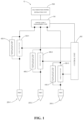
Fig. 1 shows a diagram of a sensor device according to an embodiment of the present disclosure; -
Figs. 2A-2B show diagrams of port multiplexing circuits according to different embodiments of the present disclosure; -
Figs. 3A-3B show diagrams of sensor devices when different devices are coupled according to some embodiments of the present disclosure; and -
Figs. 4A-4B show diagrams of sensor devices when different devices are coupled according to other embodiments of the present disclosure. - Various embodiments will now be described with reference to the drawings, wherein similar reference numerals are used to refer to similar elements throughout. In the following description, for purposes of explanation, numerous specific details are set forth in order to promote a thorough understanding of one or more embodiments. However, it may be clear in some or all cases that any of the embodiments described below can be practiced without adopting the specific design details described below. In other instances, well-known structures and devices are shown in block diagram form in order to facilitate the description of one or more embodiments. The following presents a simplified summary of one or more embodiments in order to provide a basic understanding of the embodiments. This summary is not an exhaustive overview of all anticipated embodiments, nor is it intended to identify key or critical elements of all embodiments, nor is it intended to define the scope of any or all embodiments.
- References to "an embodiment" or "an embodiment" in the framework of the description are intended to indicate that a particular configuration, structure or characteristic described with respect to an embodiment is included in at least one embodiment. Therefore, phrases such as "in an embodiment" or "in one embodiment" that may exist in one or more points in this description do not necessarily refer to the same embodiment. Furthermore, in one or more embodiments, specific configurations, structures, or features may be combined in any suitable manner.
- Unless otherwise indicated, when referring to two elements connected together, this means direct connection without any intermediate elements other than conductors; when referring to two elements coupled together, this means that the two elements can be connected or they can be coupled via one or more other elements.
- In the following disclosure, unless otherwise indicated, when referring to absolute position qualifiers such as "front", "back", "top", "bottom", "left", "right", etc. or relative position qualifiers such as "above", "below", "higher", "lower", etc., or directional qualifiers such as "horizontal", "longitude", the direction in the figures are indicated. Unless otherwise indicated, the expressions "about", "approximate", "basic" and "about" mean within 10%, preferably within 5%.
- The structure and working principle of a sensor device according to an embodiment of the present disclosure will be described in detail with reference to
figs. 1 to 4B . -
Fig. 1 shows a diagram of asensor device 10 according to an embodiment of the present disclosure. As shown inFig. 1 , thesensor device 10 includes a powersupply management unit 100, three port multiplexing circuits, a self-inductionpower extracting circuit 500 and acontrol unit 600. The powersupply management unit 100 can selectively receive internal electric energy from the self-inductionpower extracting circuit 500 or receive external electric energy by using the port multiplexing circuit. After that, the powersupply management unit 100 processes the received electric energy and uses the processed electric energy to supply power to the internal circuit. The powersupply management unit 100 may be coupled to an internal circuit or a device of thesensor device 10, for example, to transmit the received processed electric energy to various means. It should be understood that the port multiplexing circuit shown inFig. 1 is only an example. Thesensor device 10 may have a port multiplexing circuit and other circuits only used for signal detection. This disclosure is not intending to be limiting. - For example, the self-induction
power extracting circuit 500 can generate electric energy by using the magnetic field generated by the power supply wire of the electrical equipment where thesensor device 10 is located in accordance with the current, or it can also be any circuit capable of generating electric energy by using external energy. This disclosure is not intending to be limiting. Thecontrol unit 600 may be, for example, a microcontroller unit (MCU) in thesensor device 10. Thecontrol unit 600 is coupled to the powersupply management unit 100 and obtains electric energy from the powersupply management unit 100. Thecontrol unit 600 can receive various sensing signals of thesensor device 10 and send control signals to controlled means in thesensor device 10. - A first port multiplex circuit includes a port 200-1, and a signal detection unit 300-1 and an external auxiliary power supply switching-on unit 400-1 connected in parallel between the power
supply management unit 100 and the port 200-1. Correspondingly, a second port multiplex circuit comprises a port 200-2, a signal detection unit 300-2 and an external auxiliary power supply switching-on unit 400-2 connected in parallel between the powersupply management unit 100 and the port 200-2. A third port multiplexing circuit includes a port 200-3 (collectively referred to as aport 200 with ports 200-1 and 200-2), a signal detection unit 300-3 (collectively referred to as asignal detection unit 300 with signal detection units 300-1 and 300-2) and the external auxiliary power supply switching-on unit 400-3 connected in parallel between the powersupply management unit 100 and the port 200-3. Thesignal detection unit 300 can generate a sensing signal when theport 200 is coupled to a sensing apparatus. When theport 200 is coupled to an external auxiliary power supply, if the external auxiliary power supply switching-onunit 400 receives external electric energy from theport 200, the external auxiliary power supply switching-onunit 400 causes the received electric energy to be transmitted to the powersupply management unit 100. The specific structure of the port multiplexing circuit will be described in detail with reference tofigs. 2A- 2B . -
Fig. 2A shows a diagram of a port multiplexing circuit according to some embodiments of the present disclosure. As shown inFig. 2A , the powersupply management unit 100 includes an electricenergy conversion apparatus 110. The electricenergy conversion apparatus 110 is coupled to the self-inductionpower extracting unit 500 and configured to convert the electric energy generated by the self-inductionpower extracting unit 500 into power supply electric energy for thesensor device 10 after rectification and voltage regulation. The electricenergy conversion apparatus 110 can be, for example, a low dropout regulator (LDO). Thesignal detection unit 300 includes avoltage dividing apparatus 310 coupled between the powersupply management unit 100 and theport 200 and anoutput end 320 for outputting a signal. When thesensor device 10 is installed in an electrical device for operation, for example, theport 200 is coupled to the sensing apparatus 20 (not shown here). At this time, the electricenergy conversion apparatus 110 can convert the electric energy generated by the self-inductionpower extracting unit 500 into power supply electric energy and transmit it to thesignal detection unit 300. Thevoltage dividing apparatus 310 and thesensing apparatus 20 coupled to theport 200 divide the electric energy from the electricenergy conversion apparatus 110, and form a voltage sensing signal at the second end of thevoltage dividing apparatus 310 coupled to theport 200. In addition, afilter device 330 and abuffering apparatus 340 are connected in series between the second end of thevoltage dividing apparatus 310 and theoutput end 320. Thefiltering apparatus 330 filters the sensing signal to suppress or remove interference in the signal. Thebuffering apparatus 340 suppresses the sensing signal below a predetermined voltage threshold or a predetermined current threshold, so as to prevent thecontrol unit 600 from being damaged due to excessive voltage or current of the sensing signal. - In the embodiment shown in
Fig. 2A , the external auxiliary power supply switching-onunit 400 includes aunidirectional conduction apparatus 410. The input end of theunidirectional conduction apparatus 410 is coupled to theport 200 and output end thereof is coupled to the powersupply management unit 100. Theunidirectional conduction apparatus 410 conducts when input thereof receives external electric energy from theport 200. At this time, thesignal detection unit 300 is shorted, so that external electric energy is directly transmitted to the powersupply management unit 100. When the electric energy is transmitted from theport 200 to the powersupply management unit 100, the current direction thereof is opposite to that of the electric energy converted by the electricenergy conversion apparatus 110. In order to avoid damage to the electricenergy conversion apparatus 110, the electricenergy conversion apparatus 110 includes a reverse protection apparatus. In some embodiments, theunidirectional conduction apparatus 410 can be, for example, a diode or a triode with a corresponding controller. -
Fig. 2B shows a diagram of a port multiplexing circuit according to some embodiments of the present disclosure. Different from the circuit shown inFig. 2A , the external auxiliary power supply switching-onunit 400 of the port multiplexing circuit shown inFig. 2B includes aswitching apparatus 420. A first end of theswitching apparatus 420 is coupled to theport 200 and a second end thereof is coupled to the powersupply management unit 100. When theport 200 is coupled to the externalauxiliary power supply 20, theswitching apparatus 420 is closed, so that external electric energy is transmitted to the powersupply management unit 100. -
Fig. 3A shows a diagram of asensor device 10 when coupled to asensing apparatus 20 according to some embodiments of the present disclosure. As shown inFig. 3A , thesensor device 10 includes the powersupply management unit 100, a three-way port multiplexing circuit, a self-inductionpower extracting circuit 500 and acontrol unit 600. The first port multiplexing circuit includes the port 200-1, a signal detection unit 300-1 and a diode D-1 as an external auxiliary power supply switching-on unit 400-1. Correspondingly, the second port multiplexing circuit includes the port 200-2, the signal detection unit 300-2 and the diode D-2 as external auxiliary power supply switching-on unit 400-2. The third port multiplexing circuit includes the port 200-3, signal detection unit 300-3 and diode D-3 as external auxiliary power supply switching-on unit 400-3. The port 200-1 includes a first terminal 210-1 and a second terminal 220-1; the port 200-2 includes a first terminal 210-2 and a second terminal 220-2; the port 200-3 includes a first terminal 210-3 and a second terminal 220-3. - Specifically, the signal detection unit 300-1 includes a resistor R1-1, a capacitor C-1, a resistor R2-1 and an output end 320-1. The first end of the resistor R1-1 is coupled to the power
supply management unit 100 and the first end of the diode D-1. The second end of the resistor R1-1 is coupled to the first end of the resistor R2-1, the first end of the capacitor C-1, the second end of the diode D-1 and the first terminal 210-1 of the port 200-1. The second end of the first end of the resistor R2-1 is coupled to the output end 320-1 of the signal detection unit 300-1. Here, the resistor R1-1 is used as a voltage dividing apparatus. The capacitor C-1 and the resistor R2-1 together form an anti-aliasing filter. In addition, the resistor R2-1 also acts as a buffering apparatus alone. - Similarly, the signal detection unit 300-2 includes a resistor R1-2, a capacitor C-2, a resistor R2-2 and an output end 320-2 with the same connection mode and function as the corresponding devices in the signal detection unit 300-1. The signal detection unit 300-3 also includes a resistor R1-3, a capacitor C-3, a resistor R2-3 and an output end 320-3 with the same connection mode and function as the corresponding devices in the signal detection unit 300-1.
- In the embodiment shown in
Fig. 3A , the port 200-3 is coupled to thesensing apparatus 20. Thesensing apparatus 20 is, for example, a temperature sensor and includes a negative temperature coefficient (NTC) thermistor. At this time, the first end of NTC thermistor is coupled to the first terminal 210-3 of the port 200-3 and further coupled to the second end of resistor R1-3. Meanwhile, the second end of the NTC thermistor is coupled to the second terminal 220-3 of the port 200-3, and further grounded. In this embodiment, the powersupply management unit 100 obtains electric energy from the self-inductionpower extracting unit 500. The voltage at the cathode of diode D-3 is higher than the voltage at the anode of diode D-3, so diode D-3 is turned off. Thus, the resistor R 1- 3 and the NTC thermistor are connected in series between the powersupply management unit 100 and the ground, and divide the electric energy loaded at the first end of the resistor R1-3 from the powersupply management unit 100, thereby forming a sensing signal with a corresponding voltage at the second end of the resistor R1-3. The sensing signal reaches the output end 320-3 of the signal detection unit 300-3 through filtering and buffering to be further transmitted to thecontrol unit 600 for processing. -
Fig. 3B shows a diagram of thesensor device 10 when coupled to an externalauxiliary power supply 30 according to some embodiments of the present disclosure. In the embodiment shown inFig. 3B , the structure of thesensor device 10 is the same as that of thesensor device 10 inFig. 3A , and the structure will not be described for the sake of brevity. As shown inFig. 3B , the port 200-3 is coupled to the externalauxiliary power supply 30. The externalauxiliary power supply 30 includes, for example, a variable voltage power supply (VAPS). At this time, the anode of the externalauxiliary power supply 30 is coupled to the first terminal 210-3 of the port 200-3 and further coupled to the second terminal of the resistor R1-3. Meanwhile, the cathode of the externalauxiliary power supply 30 is coupled to the second terminal 220-3 of the port 200-3, and further grounded. In this embodiment, the powersupply management unit 100 does not obtain power from the self-inductionpower extracting unit 500 and therefore does not supply power to the signal detection unit 300-3. At this time, the voltage at the anode of diode D-3 is higher than the voltage at the cathode of diode D-3, so diode D-3 is turned on. Thus, the electric energy from the externalauxiliary power supply 30 is directly transmitted to the powersupply management unit 100 from the port 200-3, and then power is supplied from the powersupply management unit 100 to other interiors. -
Fig. 4A shows a diagram of asensor device 10 when coupled to asensing apparatus 20 according to other embodiments of the present disclosure. In the embodiment shown inFig. 4A , the powersupply management unit 100, theport 200, thesignal detection unit 300, the self-inductionpower extracting unit 500 and the control unit of thesensor device 10 are the same as those of thesensor device 10 inFig. 3A , and the structures are not described for the sake of brevity. Different from that shown inFig. 3A , the external auxiliary power supply switching-onunit 400 of each port multiplexing circuit includes P-channel MOSFETs M-1, M-2 and M-3 (collectively referred to as P-channel MOSFET M). As shown inFig. 4A , the gate of the P-channel MOSFET M is coupled to the output end of the self-inductionpower extracting unit 500, and the drain thereof is coupled to the first terminal 210 of theport 200, and the source thereof is coupled to the power supply management unit. - In this embodiment, the power from the self-induction
power extracting unit 500 is transmitted to the powersupply management unit 100 and also to the gate of the P-channel MOSFET M. At this time, the gate receives a control signal at the high electrical level and turns off the drain and source of the P-channel MOSFET M. Thus, the resistor R1-3 and the NTC thermistor are connected in series between the powersupply management unit 100 and the ground, and divide the electric energy loaded at the first end of the resistor R1-3 from the powersupply management unit 100, thereby forming a sensing signal with a corresponding voltage at the second end of the resistor R1-3. The sensing signal reaches the output end 320-3 of the signal detection unit 300-3 through filtering and buffering to be further transmitted to thecontrol unit 600 for processing. -
Fig. 4B shows a diagram of thesensor device 10 when coupled to the externalauxiliary power supply 30 according to other embodiments of the present disclosure. In the embodiment shown inFig. 4B , the structure of thesensor device 10 is the same as that of thesensor device 10 inFig. 4A , and the structure will not be described for the sake of brevity. As shown inFig. 4B , the port 200-3 is coupled to the externalauxiliary power supply 30. At this time, the anode of the externalauxiliary power supply 30 is coupled to the first terminal 210-3 of the port 200-3 and further coupled to the second terminal of the resistor R1-3. Meanwhile, the cathode of the externalauxiliary power supply 30 is coupled to the second terminal 220-3 of the port 200-3, and further grounded. In this embodiment, the powersupply management unit 100 does not obtain power from the self-inductionpower extracting unit 500 and therefore does not supply power to the signal detection unit 300-3. Meanwhile, the gate of P-channel MOSFET M-3 is at the low electrical level, which makes P-channel MOSFET M-3 conductive. Thus, the electric energy from the externalauxiliary power supply 30 is directly transmitted to the powersupply management unit 100 from the port 200-3, and then power is supplied from the powersupply management unit 100 to other interiors. - It should be understood that the
sensing apparatus 20 for detecting temperature is only exemplary, and thesensor device 10 may also be coupled to a passive sensing apparatus for measuring other physical quantities, and has a signal detection unit corresponding to the passive sensing apparatus. In some embodiments, a sensor device may be coupled to a voltage sensing apparatus and/or a current sensing apparatus, for example, to detect a voltage or a current in an electrical device. - In some embodiments, the gate of the P-channel MOSFET M may also be coupled to and receive control signals from the
control unit 600. Thecontrol unit 600 can detect the port voltage at theport 200 and send a control signal at the low electrical level to the gate when it is determined that the port voltage is higher than a predetermined threshold, and send a control signal at the high electrical level to the gate when it is determined that the port voltage is lower than a predetermined threshold. - Without prejudice to the basic principles, the details and embodiments may vary, even significantly, with respect to what has been described by way of example only, without departing from the scope of protection. The various embodiments described above can be combined to provide further embodiments. These and other changes to the embodiments can be made in light of the above detailed description. Generally, in the following claims, the terms used should not be interpreted as limiting the claims to the specific embodiments disclosed in the specification and claims, but should be interpreted as including all possible embodiments and the full scope of equivalents to which such claims are entitled. Therefore, the claims are not limited by the disclosure.
Claims (15)
- A sensor device (10), comprising:a power supply management unit (100) configured to selectively receive internal electric energy or external electric energy and supply power to an internal circuit;a port (200) adapted to be coupled to a sensing apparatus (20) or an external auxiliary power supply (30) for providing the external electric energy;a signal detection unit (300) having a first end coupled to the power supply management unit (100) and a second end coupled to the port (200), the signal detection unit (300) being configured to generate a sensing signal when the port (200) is coupled to the sensing apparatus; andan external auxiliary power supply switching-on unit (400) having a first end coupled to the power supply management unit (100) and a second end coupled to the port (200), the external auxiliary power supply switching-on unit (400) being configured to transmit the electric energy to the power supply management unit (100) in response to receiving electric energy from the port (200) when the port (200) is coupled to the external auxiliary power supply.
- The sensor device (1) according to claim 1, wherein the external auxiliary power supply switching-on unit (400) comprises a unidirectional conduction apparatus (410) having an input end coupled to the port (200) and an output end coupled to the power supply management unit (100), and the unidirectional conduction apparatus (410) is configured to conduct electricity in response to receiving electric energy from the port (200), so that the external electric energy is transmitted to the power supply management unit (100).
- The sensor device (1) according to claim 2, wherein the unidirectional conduction apparatus (410) comprises a diode (D), particularly
wherein the diode (D) is configured to clip the sensing signal when the port (200) is coupled to the sensing apparatus (20). - The sensor device (1) according to any of the preceding claims, wherein the external auxiliary power supply switching-on unit (400) comprises a switching apparatus (420) having a first end coupled to the port (200) and a second end coupled to the power supply management unit (100), and the switching apparatus (420) is configured to conduct electricity in response to the port (200) being coupled to the external auxiliary power supply (20), so that the external electric energy is transmitted to the power supply management unit (100).
- The sensor device (1) according to claim 4, wherein the switching apparatus (420) comprises:
a P-channel MOSFET(M) having a gate configured to receive a control signal, a drain coupled to the port (200) and a source coupled to the power supply management unit (100), wherein the P-channel MOSFET(M) is configured to turn off in response to the control signal being at the high electrical level and turn on in response to the control signal being at the low electrical level. - The sensor device (1) according to claim 5, wherein the gate is coupled to a self-induction power extracting unit (500) and is configured to receive the control signal from the self-induction power extracting unit (500), wherein the control signal is at the high electrical level when the self-induction power extracting unit (500) is in operation and at the low electrical level when the self-induction power extracting unit (500) is not in operation.
- The sensor device (1) according to claim 5, wherein the gate is coupled to a control unit (600) and configured to receive the control signal from the control unit (600), wherein the control unit (600) is configured to detect port voltage at the port (200) and send the control signal at the low electrical level to the gate in response to determining that the port voltage is higher than a predetermined threshold, and send the control signal at the high electrical level to the gate in response to determining that the port voltage is lower than a predetermined threshold.
- The sensor device (1) according to claim 6, wherein the self-induction power extracting unit (500) is further coupled to the power supply management unit (100) and configured to generate the internal electric energy for transmission to the power supply management unit (100).
- The sensor device (1) according to claim 8, wherein the power supply management unit (100) comprises:
an electric energy conversion apparatus (110) coupled to the self-induction power extracting unit (500) and configured to convert electric energy generated by the self-induction power extracting unit (500) into power supply electric energy of the sensor device (1) after rectification and voltage regulation. - The sensor device (1) according to claim 8, wherein the electric energy conversion apparatus (110) comprises a reverse protection apparatus.
- The sensor device (1) according to any of the preceding claims, wherein the signal detection unit (300) comprises:a filtering apparatus (330) configured to filter a sensing signal, and/ora buffering apparatus (340) configured to suppress a sensing signal below a predetermined voltage threshold or a predetermined current threshold.
- The sensor device (1) according to any of the preceding claims, wherein the signal detection unit (300) comprises a voltage dividing apparatus (310) and an output end (320), and the port (200) comprises a first terminal (210) and a second terminal (220),
wherein a first end of the voltage dividing apparatus (310) is coupled to the power supply management unit (100) and a second end is coupled to the first terminal (210) and the output end (320), and the second terminal (220) is grounded. - The sensor device (1) according to claim 12, wherein the sensing apparatus (20) comprises a thermistor, and wherein, when the port (200) is coupled to the sensing apparatus (20), a second end of the voltage dividing apparatus (310) is coupled to the thermistor such that a voltage sensing signal indicating a temperature sensed by the sensing apparatus (20) is formed at a second end of the voltage dividing apparatus (310).
- The sensor device (1) according to any of the preceding claims, comprising a set of signal detection units (300), a set of external auxiliary power supply switching-on units (400) and a set of ports (200),
wherein a first port (200) in the set of ports (200) is coupled to the sensing apparatus (20) and a second port (200) in the set of ports (200) is coupled to the external auxiliary power supply (30). - An electrical device comprising the sensor device according to any one of claims 1-14.
Applications Claiming Priority (1)
| Application Number | Priority Date | Filing Date | Title |
|---|---|---|---|
| CN202211742844.4A CN115931024B (en) | 2022-12-30 | 2022-12-30 | Sensor device and electrical device |
Publications (2)
| Publication Number | Publication Date |
|---|---|
| EP4394327A1 true EP4394327A1 (en) | 2024-07-03 |
| EP4394327B1 EP4394327B1 (en) | 2026-03-04 |
Family
ID=86555873
Family Applications (1)
| Application Number | Title | Priority Date | Filing Date |
|---|---|---|---|
| EP23198336.2A Active EP4394327B1 (en) | 2022-12-30 | 2023-09-19 | Sensor device with power supply management |
Country Status (2)
| Country | Link |
|---|---|
| EP (1) | EP4394327B1 (en) |
| CN (1) | CN115931024B (en) |
Citations (5)
| Publication number | Priority date | Publication date | Assignee | Title |
|---|---|---|---|---|
| US5717320A (en) * | 1995-11-27 | 1998-02-10 | U.S. Philips Corporation | Power supply circuit |
| US20040095107A1 (en) * | 2002-11-14 | 2004-05-20 | Kent Kernahan | Power converter circuitry and method |
| US20140001872A1 (en) * | 2012-06-28 | 2014-01-02 | Hon Hai Precision Industry Co., Ltd. | Power switching circuit and electronic device using same |
| JP2018148676A (en) * | 2017-03-03 | 2018-09-20 | 富士電機株式会社 | Switching power supply control semiconductor device |
| US20200136641A1 (en) * | 2018-10-26 | 2020-04-30 | Krohne Messtechnik Gmbh | Field Measuring Device |
Family Cites Families (23)
| Publication number | Priority date | Publication date | Assignee | Title |
|---|---|---|---|---|
| US4388534A (en) * | 1981-08-11 | 1983-06-14 | Computer Power, Inc. | Uninterruptible power supply |
| JP2001178685A (en) * | 1999-12-22 | 2001-07-03 | Olympus Optical Co Ltd | Medical electronic instrument |
| US6892216B2 (en) * | 2001-02-13 | 2005-05-10 | Snap-On Incorporated | Common platform for use in automotive services |
| CN101910832A (en) * | 2007-11-02 | 2010-12-08 | 爱德华兹生命科学公司 | Analyte monitoring system with backup power for system transfer or loss of primary power |
| US20100130263A1 (en) * | 2008-11-21 | 2010-05-27 | Edward Zhang | System and method for dual power source management |
| JP5730161B2 (en) * | 2011-09-02 | 2015-06-03 | ルネサスエレクトロニクス株式会社 | Voltage monitoring circuit, test method therefor, and voltage monitoring system |
| US8754542B2 (en) * | 2011-09-22 | 2014-06-17 | Silicon Laboratories Inc. | Apparatus including a gate drive circuit for selectively providing power to a powered device through multiple wire pairs |
| CN202872406U (en) * | 2012-09-19 | 2013-04-10 | 青岛海信移动通信技术股份有限公司 | Interface multiplexing circuit and mobile terminal |
| US20140084684A1 (en) * | 2012-09-21 | 2014-03-27 | Richtek Technology Corporation | Power supply circuit |
| US9692329B2 (en) * | 2014-08-08 | 2017-06-27 | Johnson Electric S.A. | Magnetic sensor and an integrated circuit |
| CN105576840A (en) * | 2014-11-11 | 2016-05-11 | 苏州银蕨电力科技有限公司 | Self-induction electricity taking circuit for smart power grid sensing device |
| CN204406110U (en) * | 2015-01-27 | 2015-06-17 | 中联重科股份有限公司 | Multiplexing interface device, device and system using multiplexing interface device |
| US9785211B2 (en) * | 2015-02-13 | 2017-10-10 | Qualcomm Incorporated | Independent power collapse methodology |
| KR101797218B1 (en) * | 2015-07-28 | 2017-11-13 | 이정석 | Multi control device for remote security |
| JP7257255B2 (en) * | 2019-05-29 | 2023-04-13 | 株式会社ジェイテクト | Auxiliary power supply |
| JP7251364B2 (en) * | 2019-07-02 | 2023-04-04 | オムロン株式会社 | counter unit |
| US10903649B1 (en) * | 2019-07-25 | 2021-01-26 | Abb Schweiz Ag | Static transfer switch with turn off circuit |
| KR102728656B1 (en) * | 2020-01-02 | 2024-11-08 | 주식회사 엘지에너지솔루션 | Battery management system, baptter rack, and energy storage system |
| CN211015487U (en) * | 2020-02-27 | 2020-07-14 | 青岛新基智能控制有限公司 | USB interface multiplexing circuit |
| CN212083944U (en) * | 2020-04-10 | 2020-12-04 | 基康仪器股份有限公司 | Dam safety monitoring data acquisition unit |
| CN114175506B (en) * | 2020-07-10 | 2023-05-16 | 深圳欣锐科技股份有限公司 | Pulse width modulation port multiplexing circuit and device based on digital signal processing |
| CN216872864U (en) * | 2021-09-29 | 2022-07-01 | 深圳市华思旭科技有限公司 | Mobile power supply device and electric equipment |
| CN114123434B (en) * | 2022-01-27 | 2022-04-15 | 深圳市高端无人机有限公司 | Power supply circuit and electronic device |
-
2022
- 2022-12-30 CN CN202211742844.4A patent/CN115931024B/en active Active
-
2023
- 2023-09-19 EP EP23198336.2A patent/EP4394327B1/en active Active
Patent Citations (5)
| Publication number | Priority date | Publication date | Assignee | Title |
|---|---|---|---|---|
| US5717320A (en) * | 1995-11-27 | 1998-02-10 | U.S. Philips Corporation | Power supply circuit |
| US20040095107A1 (en) * | 2002-11-14 | 2004-05-20 | Kent Kernahan | Power converter circuitry and method |
| US20140001872A1 (en) * | 2012-06-28 | 2014-01-02 | Hon Hai Precision Industry Co., Ltd. | Power switching circuit and electronic device using same |
| JP2018148676A (en) * | 2017-03-03 | 2018-09-20 | 富士電機株式会社 | Switching power supply control semiconductor device |
| US20200136641A1 (en) * | 2018-10-26 | 2020-04-30 | Krohne Messtechnik Gmbh | Field Measuring Device |
Also Published As
| Publication number | Publication date |
|---|---|
| CN115931024A (en) | 2023-04-07 |
| EP4394327B1 (en) | 2026-03-04 |
| CN115931024B (en) | 2025-12-19 |
Similar Documents
| Publication | Publication Date | Title |
|---|---|---|
| US7436087B2 (en) | Power line conditioner | |
| US9234922B2 (en) | Measuring system for monitoring at least one phase of a system | |
| US7103486B2 (en) | Device for monitoring a neutral and earth break and electrical switchgear apparatus comprising such a device | |
| WO2012059061A1 (en) | Method and device for quality-monitoring of high-voltage electrical energy | |
| RU2504067C2 (en) | System of uninterrupted power supply comprising simplified circuit of voltage availability indication | |
| KR100669157B1 (en) | Digital distribution panel measuring controller | |
| JP2015040763A (en) | Partial discharge measuring apparatus and method | |
| KR101671638B1 (en) | Apparatus for displaying and warning between ground and electric power lines | |
| KR101457878B1 (en) | A deterioration monitoring system for a distributing board on based hybrid temperature sensors with multi-points | |
| CN101420114A (en) | Multifunctional three phase power source protector | |
| RU2321916C2 (en) | Switch with built-in current and/or voltage sensor | |
| EP4600666A1 (en) | Low-power current transformer to which temperature compensation is applied, and temperature compensation method therefor | |
| EP3764111A1 (en) | Detection device | |
| EP4394327B1 (en) | Sensor device with power supply management | |
| EP4160649A1 (en) | Circuit breaker | |
| US3982181A (en) | Apparatus and method for tracing energized AC circuits | |
| US20050017734A1 (en) | Method for on-line calibration of low accuracy voltage sensor through communication bus | |
| US20150244163A1 (en) | Current and voltage module and methods of monitoring current and voltage in power distribution systems | |
| CN102332697A (en) | Measuring transient electrical activity in aircraft power distribution systems | |
| KR101415269B1 (en) | Power Distribution Panel Capable of Controlling on Real Time | |
| WO2024262686A1 (en) | Ict alert-type high-voltage distribution board having built-in energy harvesting apparatus that senses leakage and overheating | |
| RU200640U1 (en) | SECONDARY POWER SUPPLY MODULE | |
| US20230033407A1 (en) | A busbar adapter | |
| KR101864772B1 (en) | Infrared ray data transmission sensor for detecting abnormality of switchboard using potential difference | |
| CN201349120Y (en) | Multi-function three-phase power source protector |
Legal Events
| Date | Code | Title | Description |
|---|---|---|---|
| PUAI | Public reference made under article 153(3) epc to a published international application that has entered the european phase |
Free format text: ORIGINAL CODE: 0009012 |
|
| STAA | Information on the status of an ep patent application or granted ep patent |
Free format text: STATUS: REQUEST FOR EXAMINATION WAS MADE |
|
| 17P | Request for examination filed |
Effective date: 20230919 |
|
| AK | Designated contracting states |
Kind code of ref document: A1 Designated state(s): AL AT BE BG CH CY CZ DE DK EE ES FI FR GB GR HR HU IE IS IT LI LT LU LV MC ME MK MT NL NO PL PT RO RS SE SI SK SM TR |
|
| GRAP | Despatch of communication of intention to grant a patent |
Free format text: ORIGINAL CODE: EPIDOSNIGR1 |
|
| STAA | Information on the status of an ep patent application or granted ep patent |
Free format text: STATUS: GRANT OF PATENT IS INTENDED |
|
| INTG | Intention to grant announced |
Effective date: 20251024 |
|
| GRAS | Grant fee paid |
Free format text: ORIGINAL CODE: EPIDOSNIGR3 |
|
| GRAA | (expected) grant |
Free format text: ORIGINAL CODE: 0009210 |
|
| STAA | Information on the status of an ep patent application or granted ep patent |
Free format text: STATUS: THE PATENT HAS BEEN GRANTED |
|
| AK | Designated contracting states |
Kind code of ref document: B1 Designated state(s): AL AT BE BG CH CY CZ DE DK EE ES FI FR GB GR HR HU IE IS IT LI LT LU LV MC ME MK MT NL NO PL PT RO RS SE SI SK SM TR |
|
| REG | Reference to a national code |
Ref country code: CH Ref legal event code: F10 Free format text: ST27 STATUS EVENT CODE: U-0-0-F10-F00 (AS PROVIDED BY THE NATIONAL OFFICE) Effective date: 20260304 Ref country code: GB Ref legal event code: FG4D |
|
| REG | Reference to a national code |
Ref country code: IE Ref legal event code: FG4D |
|
| REG | Reference to a national code |
Ref country code: DE Ref legal event code: R096 Ref document number: 602023012907 Country of ref document: DE |