EP4394294A1 - Drying device - Google Patents
Drying device Download PDFInfo
- Publication number
- EP4394294A1 EP4394294A1 EP23765728.3A EP23765728A EP4394294A1 EP 4394294 A1 EP4394294 A1 EP 4394294A1 EP 23765728 A EP23765728 A EP 23765728A EP 4394294 A1 EP4394294 A1 EP 4394294A1
- Authority
- EP
- European Patent Office
- Prior art keywords
- air
- port
- drying
- communication
- drying device
- Prior art date
- Legal status (The legal status is an assumption and is not a legal conclusion. Google has not performed a legal analysis and makes no representation as to the accuracy of the status listed.)
- Pending
Links
Images

Classifications
-
- F—MECHANICAL ENGINEERING; LIGHTING; HEATING; WEAPONS; BLASTING
- F26—DRYING
- F26B—DRYING SOLID MATERIALS OR OBJECTS BY REMOVING LIQUID THEREFROM
- F26B3/00—Drying solid materials or objects by processes involving the application of heat
- F26B3/02—Drying solid materials or objects by processes involving the application of heat by convection, i.e. heat being conveyed from a heat source to the materials or objects to be dried by a gas or vapour, e.g. air
- F26B3/04—Drying solid materials or objects by processes involving the application of heat by convection, i.e. heat being conveyed from a heat source to the materials or objects to be dried by a gas or vapour, e.g. air the gas or vapour circulating over or surrounding the materials or objects to be dried
-
- F—MECHANICAL ENGINEERING; LIGHTING; HEATING; WEAPONS; BLASTING
- F26—DRYING
- F26B—DRYING SOLID MATERIALS OR OBJECTS BY REMOVING LIQUID THEREFROM
- F26B13/00—Machines and apparatus for drying fabrics, fibres, yarns, or other materials in long lengths, with progressive movement
- F26B13/10—Arrangements for feeding, heating or supporting materials; Controlling movement, tension or position of materials
- F26B13/101—Supporting materials without tension, e.g. on or between foraminous belts
- F26B13/104—Supporting materials without tension, e.g. on or between foraminous belts supported by fluid jets only; Fluid blowing arrangements for flotation dryers, e.g. coanda nozzles
-
- F—MECHANICAL ENGINEERING; LIGHTING; HEATING; WEAPONS; BLASTING
- F26—DRYING
- F26B—DRYING SOLID MATERIALS OR OBJECTS BY REMOVING LIQUID THEREFROM
- F26B13/00—Machines and apparatus for drying fabrics, fibres, yarns, or other materials in long lengths, with progressive movement
- F26B13/10—Arrangements for feeding, heating or supporting materials; Controlling movement, tension or position of materials
-
- F—MECHANICAL ENGINEERING; LIGHTING; HEATING; WEAPONS; BLASTING
- F26—DRYING
- F26B—DRYING SOLID MATERIALS OR OBJECTS BY REMOVING LIQUID THEREFROM
- F26B21/00—Arrangements for supplying or controlling air or other gases for drying solid materials or objects
- F26B21/20—Circulating air or gases in closed cycles, e.g. wholly within the drying enclosure
- F26B21/202—Circulating air or gases in closed cycles, e.g. wholly within the drying enclosure with means for changing the flow pattern, e.g. by reversing gas flow or by moving the materials or objects through subsequent compartments, at least two of which have a different flow direction
- F26B21/208—Circulating air or gases in closed cycles, e.g. wholly within the drying enclosure with means for changing the flow pattern, e.g. by reversing gas flow or by moving the materials or objects through subsequent compartments, at least two of which have a different flow direction by air valves, movable baffles or nozzle arrangements
-
- F—MECHANICAL ENGINEERING; LIGHTING; HEATING; WEAPONS; BLASTING
- F26—DRYING
- F26B—DRYING SOLID MATERIALS OR OBJECTS BY REMOVING LIQUID THEREFROM
- F26B21/00—Arrangements for supplying or controlling air or other gases for drying solid materials or objects
- F26B21/20—Circulating air or gases in closed cycles, e.g. wholly within the drying enclosure
- F26B21/25—Circulating air or gases in closed cycles, e.g. wholly within the drying enclosure partly outside the drying enclosure
-
- F—MECHANICAL ENGINEERING; LIGHTING; HEATING; WEAPONS; BLASTING
- F26—DRYING
- F26B—DRYING SOLID MATERIALS OR OBJECTS BY REMOVING LIQUID THEREFROM
- F26B21/00—Arrangements for supplying or controlling air or other gases for drying solid materials or objects
- F26B21/30—Controlling, e.g. regulating, parameters of gas supply
- F26B21/37—Velocity of flow; Quantity of flow
-
- F—MECHANICAL ENGINEERING; LIGHTING; HEATING; WEAPONS; BLASTING
- F26—DRYING
- F26B—DRYING SOLID MATERIALS OR OBJECTS BY REMOVING LIQUID THEREFROM
- F26B21/00—Arrangements for supplying or controlling air or other gases for drying solid materials or objects
- F26B21/50—Ducting arrangements from the source of air or other gases to the materials or objects being dried
-
- H—ELECTRICITY
- H01—ELECTRIC ELEMENTS
- H01M—PROCESSES OR MEANS, e.g. BATTERIES, FOR THE DIRECT CONVERSION OF CHEMICAL ENERGY INTO ELECTRICAL ENERGY
- H01M4/00—Electrodes
- H01M4/02—Electrodes composed of, or comprising, active material
- H01M4/04—Processes of manufacture in general
-
- B—PERFORMING OPERATIONS; TRANSPORTING
- B05—SPRAYING OR ATOMISING IN GENERAL; APPLYING FLUENT MATERIALS TO SURFACES, IN GENERAL
- B05D—PROCESSES FOR APPLYING FLUENT MATERIALS TO SURFACES, IN GENERAL
- B05D2252/00—Sheets
- B05D2252/02—Sheets of indefinite length
-
- B—PERFORMING OPERATIONS; TRANSPORTING
- B05—SPRAYING OR ATOMISING IN GENERAL; APPLYING FLUENT MATERIALS TO SURFACES, IN GENERAL
- B05D—PROCESSES FOR APPLYING FLUENT MATERIALS TO SURFACES, IN GENERAL
- B05D3/00—Pretreatment of surfaces to which liquids or other fluent materials are to be applied; After-treatment of applied coatings, e.g. intermediate treating of an applied coating preparatory to subsequent applications of liquids or other fluent materials
- B05D3/04—Pretreatment of surfaces to which liquids or other fluent materials are to be applied; After-treatment of applied coatings, e.g. intermediate treating of an applied coating preparatory to subsequent applications of liquids or other fluent materials by exposure to gases
- B05D3/0406—Pretreatment of surfaces to which liquids or other fluent materials are to be applied; After-treatment of applied coatings, e.g. intermediate treating of an applied coating preparatory to subsequent applications of liquids or other fluent materials by exposure to gases the gas being air
- B05D3/0413—Heating with air
-
- Y—GENERAL TAGGING OF NEW TECHNOLOGICAL DEVELOPMENTS; GENERAL TAGGING OF CROSS-SECTIONAL TECHNOLOGIES SPANNING OVER SEVERAL SECTIONS OF THE IPC; TECHNICAL SUBJECTS COVERED BY FORMER USPC CROSS-REFERENCE ART COLLECTIONS [XRACs] AND DIGESTS
- Y02—TECHNOLOGIES OR APPLICATIONS FOR MITIGATION OR ADAPTATION AGAINST CLIMATE CHANGE
- Y02E—REDUCTION OF GREENHOUSE GAS [GHG] EMISSIONS, RELATED TO ENERGY GENERATION, TRANSMISSION OR DISTRIBUTION
- Y02E60/00—Enabling technologies; Technologies with a potential or indirect contribution to GHG emissions mitigation
- Y02E60/10—Energy storage using batteries
Definitions
- the drying oven further includes a third air nozzle disposed on the second surface, the third air nozzle has a third air nozzle tip in communication with the air suction port, and the axial direction of the third air nozzle tip is parallel to the extension direction of the drying channel. Since the plane where the third air nozzle tip is located is parallel to the extension direction of the drying channel, the suction direction of the third air nozzle tip may be parallel to the extension direction of the drying channel, and then the air suction port in communication with the third air nozzle tip produces a suction force to act to the utmost extent on the part to be dried that is located in the drying channel, thus improving the capability to weaken the shear force.
- the drying device further includes a circulating fan, the circulating fan has an air inlet and an air outlet, the air inlet is in communication with the air suction port, and the air outlet is in communication with the first air blow port. Since the circulating fan is provided, the first blow port, the drying channel, the air suction port, and the circulating fan form a circulating loop, which can be conducive to internal circulation of an air field, avoids internal dissipation, and makes the drying atmosphere inside the drying channel more uniform, thus improving the drying efficiency.
- the circulating fan is a variable-frequency fan. Since the variable-frequency fan is disposed in the circulating loop, the air volume can be regulated in real time according to drying situations, energy consumption for operation is minimized, and the overall benefit is maximized.
- the drying device further includes a first air volume regulation valve, the first air volume regulation valve is in communication with the first air blow port, and the first air volume regulation valve is controlled to regulate the air blow volume of the first air blow port. Since the first air volume regulation valve is provided to regulate the air blow volume of the first air blow port, the air volume can be flexibly regulated, and accordingly it is feasible to regulate the part to be dried in different suspension states.
- the drying device further includes a second air volume regulation valve, the second air volume regulation valve is in communication with the air suction port, and the second air volume regulation valve is controlled to regulate the air suction volume of the air suction port. Since the second air volume regulation valve is provided to regulate the air suction volume of the air suction port, the air volume can be flexibly regulated, and accordingly it is feasible to regulate the part to be dried in different suspension states.
- the second surface is further provided with a second air blow port, and the second air blow port is spaced apart from the air suction port.
- the second air blow port can blow air into the drying channel to dry one side surface of the part to be dried.
- the second air blow port may cooperate with the first air blow port to dry both side surfaces of the part to be dried.
- an embodiment means that a particular feature, structure, or characteristic described in connection with the embodiment can be included in at least one embodiment of the present application.
- the appearance of this phrase in various places in the specification does not necessarily refer to the same embodiment, nor is it a separate or alternative embodiment that is mutually exclusive with other embodiments. It is explicitly or implicitly understood by persons skilled in the art that the embodiments described herein may be combined with other embodiments.
- the technical terms “mount,” “join,” “connect,” “fix,” etc. should be understood in a broad sense, such as, a fixed connection, a detachable connection, or an integral connection; a mechanical connection, or an electrical connection; a direct connection, an indirect connection through an intermediate medium, an internal connection of two elements, or interaction between two elements.
- the specific meanings of the above terms in the embodiments of the present application can be understood according to specific situations.
- Lithium-ion batteries have been widely used in electronic products in various fields due to their advantages such as high energy density and environmental friendliness.
- electric vehicle technology the application of lithium-ion batteries in the field of electric vehicles has attracted much attention.
- a lithium-ion battery is usually composed of a positive electrode, a negative electrode, a separator, an electrolyte and a shell.
- the positive and negative electrode plates and the separator isolated therein can be wound to obtain a cell.
- the negative electrode plate includes a negative electrode current collector generally made of aluminum foil, and a film containing a negative electrode active material and attached to the negative electrode current collector.
- the positive electrode plate includes a positive electrode current collector generally made of copper foil, and a film containing a positive electrode active material and attached to the positive electrode current collector.
- the separator is a microporous film made by plasticizing, extraction, and other processes.
- the drying oven includes an upper covering and a lower covering, the upper covering and the lower covering are arranged opposite to each other to form a drying channel, and drying hot air of the drying oven is blown out from slits of an upper blow port fixed to the upper covering and a lower blow port fixed to the lower covering, so that the hot air can play a role in drying, lifting, flattening, and the like.
- the drying device disclosed in the embodiments of the present application may, but is not limited to, be used for drying a part to be dried 200 such as an electrode plate for lithium batteries.
- Fig. 1 is a schematic perspective diagram of a drying device according to some embodiments of the present application
- Fig. 2 is a front-view schematic structural diagram of a drying device according to some embodiments of the present application.
- the present application provides a drying device 100 used for drying the part to be dried 200.
- the drying 100 includes a drying oven 10.
- the drying oven 10 has a first surface 11 and a second surface 12, and the first surface 11 and the second surface 12 are arranged opposite to and spaced apart from each other to form a drying channel 13 allowing the part to be dried 200 to pass through.
- the first surface 11 is provided with a first air blow port 111
- the first surface 11 and/or the second surface 12 is provided with an air exhaust port 121.
- the second surface 12 is further provided with an air suction port 122.
- direction Y in the figure is a height direction of the drying oven 10
- direction X is a length direction of the drying oven 10, i.e., an extension direction of the drying channel 13 of the drying oven 10.
- the first air blow port 111 has an effect of drying one side surface of the part to be dried 200 because it blows air into the drying channel 13.
- the drying oven 10 includes a body 14 and a first air nozzle 15, a second air nozzle 16 and a third air nozzle 17 that are disposed on the body 14.
- the body 14 has a first surface 11 and a second surface 12.
- the first air nozzle 15 is disposed on the first surface 11 and has a first air nozzle tip 151, and the first air nozzle tip 151 is in communication with the first air blow port 111.
- the second air nozzle 16 is disposed on the first surface 11 and/or the second surface 12 and has a second air nozzle tip 161, and the second air nozzle tip 161 is in communication with the air exhaust port 121.
- the third air nozzle 17 is disposed on the second surface 12 and has a third air nozzle tip 171, and the third air nozzle tip 171 is in communication with the air suction port 122.
- the upper covering 141 and the lower covering 142 have entrance and exit at both ends along the length direction of the drying oven 10 that are both in communication with the drying channel 13, and the part to be dried 200 enters the drying channel 13 from the entrance, and then is delivered from the exit after being dried in the drying channel 13.
- one of the upper covering or the lower covering is further provided with an air exhaust port 121, so that when the upper blow port blows hot air to the electrode plate, the hot air rebounds with moisture to the air exhaust port 121 on the same side, which is then discharged to prevent the moisture from remaining in the drying channel.
- the air exhaust port 121 may also have a certain suction power, which may be provided by a rear fan, to improve the air exhaust efficiency.
- the air suction port 122 opposite to the first air blow port 111 is provided additionally on the basis of the original air exhaust port 121, under the action of two airflows in the same direction, shear stress produced to the electrode plate by air blown from the upper air blow port and the lower air blow port can be weakened, and thus various abnormal conditions such as cracks, dark traces, bulges, and uneven edges are eliminated.
- Suspension of the part to be dried 200 within the drying channel 13 refers to that the part to be dried 200 can overcome gravity under air force and be lifted by the airflows to be suspended within the drying channel 13.
- the drying oven 10 further includes a second air nozzle 16 disposed on the first surface 11 and/or the second surface 12, the second air nozzle 16 has a second air nozzle tip 161 in communication with the air exhaust port 121, and the plane where the second air nozzle tip 161 is located is inclined relative to the extension direction of the drying channel 13.
- the plane where the second air nozzle tip 161 is located is a plane that overlaps with the second air nozzle tip 161.
- the hot air When hot air is blown from the first air blow port 111 to the part to be dried 200, the hot air rebounds with moisture to the air exhaust port 121 on the same side, which is then discharged to prevent the moisture from remaining in the drying channel 13. Since the second air nozzle tip 161 of the second air nozzle 161 is in communication with the air exhaust port 121 and the plane where the second air nozzle tip 161 is located is inclined relative to the extension direction of the drying channel 13, the second air nozzle tip 161 may face towards a rebound direction of hot air as much as possible, so that the hot air with moisture can be quickly discharged from the air exhaust port 121, thus improving the air exhaust effect.
- the second air nozzle 16 has two second air nozzle tips 161, the two second air nozzle tips 161 are disposed at an angle, and the plane where each of the second air nozzle tips 161 is located is inclined relative to the extension direction of the drying channel 13. In this way, the hot air is discharged through both sides, which improves the air exhaust efficiency.
- the drying oven 10 further includes a third air nozzle 17 disposed on the second surface 12, the third air nozzle 17 has a third air nozzle tip 171 in communication with the air suction port 122, and the plane where the third air nozzle tip 171 is located is parallel to the extension direction of the drying channel 13.
- the plane where the third air nozzle tip 171 is located is a plane that overlaps with the third air nozzle tip 171.
- the suction direction of the third air nozzle tip 171 is parallel to the extension direction of the drying channel 13, and the air suction port 122 in communication with the third air nozzle tip 171 produces a suction force to act to the utmost extent on the part to be dried 200 that is located in the drying channel 13, thus improving the capability to weaken the shear force.
- the plane where the second air nozzle tip 161 is located is inclined relative to the extension direction of the drying channel 13 and the plane where the third air nozzle tip 171 is located is parallel to the extension direction of the drying channel 13. In this way, not only the air exhaust effect can be improved, but also the capability to weaken the shear force can be improved.
- the air suction port 122 is arranged directly opposite the first air blow port 111.
- the air suction port 122 being arranged directly opposite the first air blow port 111 means that the air suction port 122 and the first air blow port 111 face each other, and the center line of the air suction port 122 and the center line of the first air blow port 111 are on the same straight line.
- the air suction port 122 is arranged directly opposite the first air blow port 111 along the height direction of the drying oven 10. More specifically, the first air nozzle tip 151 is arranged directly opposite the third air nozzle tip 171. Further, the plane where the first air nozzle tip 151 is located is parallel to the plane where the third air nozzle tip 171 is located. Furthermore, the plane where the first air nozzle tip 151 is located and the plane where the third air nozzle tip 171 is located are both parallel to the drying channel 13.
- the air suction port 122 is directly opposite the first air blow port 111, a stress region of the part to be dried 200 that is subjected to force from the first air blow port 111 overlaps with a stress region of the part to be dried 200 that is subjected to suction from the air suction port 122. Therefore, on the one hand, force is concentrated to weaken the shear stress, and on the other hand, damage to the part to be dried 200 due to uneven stress can also be avoided.
- the first surface is provided with a plurality of first air blow ports 111 that are spaced apart and the second surface is provided with a plurality of air suction ports 122 that are spaced apart, along the extension direction of the drying channel 13.
- each of the first air blow ports 111 is arranged directly opposite one corresponding air suction port 122.
- the plurality of first air blow ports 111 are spaced apart on the first surface, which may be arranged at an equal interval or an unequal interval.
- the plurality of air suction ports 122 are spaced apart on the second surface, which may be arranged at an equal interval or an unequal interval. Compared to the way of being arranged at an unequal interval, the way of being arranged at an equal interval enables the air force applied to the part to be dried 200 to be more uniform.
- the shear force can be weakened throughout the drying process of the part to be dried 200, thereby improving the overall process yield and safety performance of the part to be dried 200.
- the drying device 100 further includes a circulating fan 20, the circulating fan 20 has an air inlet 21 and an air outlet 22, the air inlet 21 is in communication with the air suction port 122, and the air outlet 22 is in communication with the first air blow port 111.
- the drying device 100 further includes a first pipe 30 and a second pipe 40, the air inlet 21 of the circulating fan 20 is in communication with the air suction port 122 via the first pipe 30, and the air outlet 22 is in communication with the first blow port 111 via the second pipe 40.
- the circulating fan 20 Since the circulating fan 20 is provided, the first blow port 111, the drying channel 13, the air suction port 122, and the circulating fan 20 form a circulating loop, which can be conducive to internal circulation of an air field, avoids internal dissipation, and makes the drying atmosphere inside the drying channel 13 more uniform, thus improving the drying efficiency.
- second air blow port 123 and the third air blow port 112 are also similarly disposed on the air nozzles, which is not described in detail herein.
Landscapes
- Engineering & Computer Science (AREA)
- Mechanical Engineering (AREA)
- General Engineering & Computer Science (AREA)
- Textile Engineering (AREA)
- Manufacturing & Machinery (AREA)
- Chemical & Material Sciences (AREA)
- Chemical Kinetics & Catalysis (AREA)
- Electrochemistry (AREA)
- General Chemical & Material Sciences (AREA)
- Life Sciences & Earth Sciences (AREA)
- Microbiology (AREA)
- Drying Of Solid Materials (AREA)
Abstract
Description
- The present application refers to the
Chinese patent application No. 2022205215512 filed on March 10, 2022 - The present application relates to the field of battery processing and manufacturing technologies, and in particular to a drying device.
- In the manufacturing of lithium-ion batteries, according to process requirements, it is necessary to dry the wet coated electrode plates by means of a drying oven to obtain uniformly coated electrode plates with a specified thickness, and accordingly the drying process plays a vital role in production of electrode plates of batteries.
- However, the existing drying process is prone to abnormal conditions such as cracks and dark traces that seriously affect the process yield and safety performance of products.
- In view of the above problems, the present application provides a drying device, which can prevent electrode plates from various abnormal conditions such as cracks, dark traces, bulges and uneven edges that seriously affect the process yield and safety performance of products.
- The present application provides a drying device used for drying a part to be dried. The drying device includes:
- a drying oven having a first surface and a second surface, the first surface and the second surface being arranged opposite to and spaced apart from each other to form a drying channel allowing the part to be dried to pass through, the first surface being provided with a first air blow port, and the first surface and/or the second surface being provided with an air exhaust port;
- wherein the second surface is further provided with an air suction port.
- In the drying device, since the air suction port opposite to the first air blow port is provided additionally, under the action of two airflows in the same direction, shear stress produced to an electrode plate by air blown from an upper air blow port and a lower air blow port can be weakened, and thus various abnormal conditions such as cracks, dark traces, bulges, and uneven edges are eliminated.
- In some embodiments, the first air blow port and the air suction port are used to apply force to the part to be dried to suspend the part to be dried within the drying channel. The part to be dried is allowed to suspend in the drying channel, so that the problems such as scratches on nozzles and breaking of the part to be dried, or even poor drying, because the part to be dried cannot be lifted.
- In some embodiments, the drying oven further includes a second air nozzle disposed on the first surface and/or the second surface, the second air nozzle has a second air nozzle tip in communication with the air exhaust port, and the plane where the second air nozzle tip is located is inclined relative to an extension direction of the drying channel. In this way, the second air nozzle tip faces towards a rebound direction of hot air as much as possible, and hot air with moisture can be quickly discharged from the air exhaust port, thereby improving the air exhaust effect.
- In some embodiments, the drying oven further includes a third air nozzle disposed on the second surface, the third air nozzle has a third air nozzle tip in communication with the air suction port, and the axial direction of the third air nozzle tip is parallel to the extension direction of the drying channel. Since the plane where the third air nozzle tip is located is parallel to the extension direction of the drying channel, the suction direction of the third air nozzle tip may be parallel to the extension direction of the drying channel, and then the air suction port in communication with the third air nozzle tip produces a suction force to act to the utmost extent on the part to be dried that is located in the drying channel, thus improving the capability to weaken the shear force.
- In some embodiments, the drying oven further includes a second air nozzle disposed on the first surface and/or the second surface, the second air nozzle has a second air nozzle tip in communication with the air exhaust port, and the plane where the second air nozzle tip is located is inclined relative to the extension direction of the drying channel; and the drying oven further includes a third air nozzle disposed on the second surface, the third air nozzle has a third air nozzle tip in communication with the air suction port, and the plane where the third air nozzle tip is located is parallel to the extension direction of the drying channel. It not only enhances the air exhaust effect, but also improves the capability to weaken the shear force.
- In some embodiments, the air suction port is arranged directly opposite the first air blow port. Since the air suction port is arranged directly opposite the first air blow port, a stress region of the part to be dried that is subjected to force from the first air blow port overlaps with a stress region of the part to be dried that is subjected to suction from the air suction port. Therefore, on the one hand, force is concentrated to weaken the shear stress, and on the other hand, damage to the part to be dried due to uneven stress can also be avoided.
- In some embodiments, the first surface is provided with a plurality of first air blow ports that are spaced apart and the second surface is provided with a plurality of air suction ports that are spaced apart, along the extension direction of the drying channel. With the plurality of first air blow ports and the plurality of air suction ports, the shear force can be weakened throughout the drying process of the part to be dried, thereby improving the overall process yield and safety performance of the part to be dried.
- In some embodiments, the drying device further includes a circulating fan, the circulating fan has an air inlet and an air outlet, the air inlet is in communication with the air suction port, and the air outlet is in communication with the first air blow port. Since the circulating fan is provided, the first blow port, the drying channel, the air suction port, and the circulating fan form a circulating loop, which can be conducive to internal circulation of an air field, avoids internal dissipation, and makes the drying atmosphere inside the drying channel more uniform, thus improving the drying efficiency.
- In some embodiments, the first surface is provided with a plurality of first air blow ports and the second surface is provided with a plurality of air suction ports, along the extension direction of the drying channel;
- all the air suction ports are in communication with the air inlet of the same circulating fan, and all the first air blow ports are in communication with the air outlet of the same circulating fan. Since all the air suction ports are in communication with the air inlet of the same circulating fan, and all the first air blow ports are in communication with the air outlet of the same circulating fan, it is possible to simplify the overall structure. Moreover, since the same circulating fan controls the air volume, it is easy to control the air volume.
- In some embodiments, the first surface is provided with a plurality of first air blow ports and the second surface is provided with a plurality of air suction ports, along the extension direction of the drying channel;
a plurality of circulating fans are provided, the air inlet of each of the circulating fans is in communication with one of the air suction ports, and the air outlet of each of the circulating fans is in communication with one corresponding first air blow port. Since the air inlet of each of the circulating fans is in communication with one of the air suction ports, and the air outlet of each of the circulating fans is in communication with one corresponding first air blow port, the corresponding circulating fan can be adjusted individually, and the air volume can be controlled separately, thus making the regulation more flexible. - In some embodiments, the circulating fan is a variable-frequency fan. Since the variable-frequency fan is disposed in the circulating loop, the air volume can be regulated in real time according to drying situations, energy consumption for operation is minimized, and the overall benefit is maximized.
- In some embodiments, the drying device further includes a first air volume regulation valve, the first air volume regulation valve is in communication with the first air blow port, and the first air volume regulation valve is controlled to regulate the air blow volume of the first air blow port. Since the first air volume regulation valve is provided to regulate the air blow volume of the first air blow port, the air volume can be flexibly regulated, and accordingly it is feasible to regulate the part to be dried in different suspension states.
- In some embodiments, the drying device further includes a second air volume regulation valve, the second air volume regulation valve is in communication with the air suction port, and the second air volume regulation valve is controlled to regulate the air suction volume of the air suction port. Since the second air volume regulation valve is provided to regulate the air suction volume of the air suction port, the air volume can be flexibly regulated, and accordingly it is feasible to regulate the part to be dried in different suspension states.
- In some embodiments, the drying device further includes a first air volume regulation valve, the first air volume regulation valve is in communication with the first air blow port, and the first air volume regulation valve is controlled to regulate the air blow volume of the first air blow port; the drying device further includes a second air volume regulation valve, the second air volume regulation valve is in communication with the air suction port, and the second air volume regulation valve is controlled to regulate the air suction volume of the air suction port. In this way, both the air blow volume of the first air blow port and the air suction volume of the air suction port can be regulated.
- In some embodiments, the second surface is further provided with a second air blow port, and the second air blow port is spaced apart from the air suction port. The second air blow port can blow air into the drying channel to dry one side surface of the part to be dried. Thus, the second air blow port may cooperate with the first air blow port to dry both side surfaces of the part to be dried.
- The above description is only a summary of the technical solutions of the present application. In order to be able to understand the technical means of the present application more clearly, the technical means can be implemented according to the content of the specification. Furthermore, to make the above and other objectives, features and advantages of the present application more comprehensible, specific embodiments of the present application are exemplified below.
- By reading the detailed description of the preferred implementations below, various other advantages and benefits will become apparent to those of ordinary skill in the art. The drawings are for the purpose of illustrating the preferred implementations only and are not to be considered a limitation to the present application. In addition, the like components are denoted by the like reference numerals throughout the drawings. In the drawings:
-
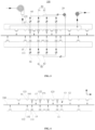
Fig. 1 is a schematic structural diagram of a drying device according to some embodiments of the present application; -
Fig. 2 is a front-view schematic structural diagram of a drying device according to some embodiments of the present application; -
Fig. 3 is a front-view schematic structural diagram of a drying device according to some embodiments of the present application; and -
Fig. 4 is a front-view schematic structural diagram of a drying device according to some embodiments of the present application. - Reference signs in specific embodiments are as follows:
-
drying device 100; -
drying oven 10,first surface 11, firstair blow port 111,second surface 12,air exhaust port 121,air suction port 122, secondair blow port 123, thirdair blow port 112,drying channel 13, body 14,upper covering 141, lower covering 142,first air nozzle 15, firstair nozzle tip 151,second air nozzle 16, secondair nozzle tip 161,third air nozzle 17, thirdair nozzle tip 171; - circulating
fan 20, air inlet 21, air outlet 22; -
first pipe 30,first section 31,second section 32; -
second pipe 40, third section 41, fourth section 42; - first air
volume regulation valve 50; - second air
volume regulation valve 60; and - part to be dried 200.
- Embodiments of the technical solutions of the present application will be described in detail below in conjunction with the drawings. The following embodiments are only used to more clearly illustrate the technical solutions of the present application, and therefore are only used as examples and cannot be used to limit the scope of protection of the present application.
- Unless otherwise defined, all technical and scientific terms used herein have the same meaning as commonly understood by those skilled in the art belonging to the technical field of the present application; the terms used herein are intended only for the purpose of describing specific embodiments and are not intended to limit the present application; the terms "including" and "having" and any variations thereof in the Specification and the Claims of the present application and in the description of drawings above are intended to cover non-exclusive inclusion.
- In the description of the embodiments of the present application, the technical terms "first", "second", and the like are used only to distinguish between different objects, and are not to be understood as indicating or implying a relative importance or implicitly specifying the number, particular order, or primary and secondary relation of the technical features indicated. In the description of the embodiments of the present application, the meaning of "a plurality of" is two or more, unless otherwise explicitly and specifically defined.
- Reference herein to "an embodiment" means that a particular feature, structure, or characteristic described in connection with the embodiment can be included in at least one embodiment of the present application. The appearance of this phrase in various places in the specification does not necessarily refer to the same embodiment, nor is it a separate or alternative embodiment that is mutually exclusive with other embodiments. It is explicitly or implicitly understood by persons skilled in the art that the embodiments described herein may be combined with other embodiments.
- In the description of the embodiments of the present application, the term "and/or" is only an association relationship for describing associated objects, indicating that there may be three relationships, for example 1 and/or 2 may represent three situations: 1 exists alone, both 1 and 2 exist, and 2 exists alone. In addition, the character "/" herein generally represents that previous and next associated objects form an "or" relationship.
- In the description of the embodiments of the present application, the term "a plurality of" refers to two or more (including two), and similarly, "multiple groups" refers to two or more (including two) groups, and "multiple sheets" refers to two or more (including two) sheets.
- In the description of the embodiments of the present application, the orientation or position relationship indicated by the technical terms "center" , "longitudinal" , "transverse" , "length" , "width" , "thickness" , "upper," "lower," "front," "back," "left," "right," "vertical," "horizontal," "top," "bottom," "inner," "outer," "clockwise," "counterclockwise," "axial" , "radial", "circumferential" , etc. are based on the orientation or position relationship shown in the drawings and are intended to facilitate the description of the embodiments of the present application and simplify the description only, rather than indicating or implying that the device or element referred to must have a particular orientation or be constructed and operated in a particular orientation, and therefore are not to be interpreted as limitations on the embodiments of the present application.
- In the description of the embodiments of the present application, unless otherwise expressly specified and limited, the technical terms "mount," "join," "connect," "fix," etc. should be understood in a broad sense, such as, a fixed connection, a detachable connection, or an integral connection; a mechanical connection, or an electrical connection; a direct connection, an indirect connection through an intermediate medium, an internal connection of two elements, or interaction between two elements. For those of ordinary skill in the art, the specific meanings of the above terms in the embodiments of the present application can be understood according to specific situations.
- With the development of science and technology, more and more electronic products enter every aspect of people's lives, and the normal use of electronic products needs batteries. Lithium-ion batteries have been widely used in electronic products in various fields due to their advantages such as high energy density and environmental friendliness. With the development of electric vehicle technology, the application of lithium-ion batteries in the field of electric vehicles has attracted much attention.
- At present, a lithium-ion battery is usually composed of a positive electrode, a negative electrode, a separator, an electrolyte and a shell. The positive and negative electrode plates and the separator isolated therein can be wound to obtain a cell. The negative electrode plate includes a negative electrode current collector generally made of aluminum foil, and a film containing a negative electrode active material and attached to the negative electrode current collector. The positive electrode plate includes a positive electrode current collector generally made of copper foil, and a film containing a positive electrode active material and attached to the positive electrode current collector. The separator is a microporous film made by plasticizing, extraction, and other processes. In the manufacturing of lithium-ion batteries, according to the process requirements, it is necessary to dry the wet coated electrode plates by means of a drying oven to obtain uniformly coated electrode plates with a specified thickness, and accordingly the drying process plays a vital role in production of electrode plates of batteries.
- In the conventional technology, the drying oven includes an upper covering and a lower covering, the upper covering and the lower covering are arranged opposite to each other to form a drying channel, and drying hot air of the drying oven is blown out from slits of an upper blow port fixed to the upper covering and a lower blow port fixed to the lower covering, so that the hot air can play a role in drying, lifting, flattening, and the like.
- However, the inventor found that, in order to ensure that an electrode plate is dry, it is necessary to increase the volume of hot air, so shear stress may be produced to the electrode plate when the hot air is blown to surfaces of the electrode plate from the upper air blow port and the lower air blow port; when the shear stress is too large, it will lead to abnormal conditions such as cracks, dark traces, bulges and uneven edges; and when the air volume is too small, the electrode plate can not be lifted, which may lead to scratches on nozzles and breaking of the electrode plate, and even lead to poor drying and other problems.
- Based on the above considerations, in order to solve the abnormal conditions such as cracks, dark traces, bulges, and uneven edges that are caused by the excessive shear force on the electrode plate due to the large hot air volume during the drying process of the electrode plate, as well as the problem that the electrode plate cannot be lifted due to the small hot air volume, the inventor, after in-depth research, has designed a drying device. An air suction port arranged opposite the lower blow port is provided additionally, an air outlet direction of the lower blow port is opposite to an air suction direction of the air suction port, so that the electrode plate can be subjected to two upward forces, thereby weakening the shear stress produced to the electrode plate by air blown from the upper blow port and the lower blow port, and eliminating abnormal conditions such as cracks, dark traces, bulges, and uneven edges.
- The drying device disclosed in the embodiments of the present application may, but is not limited to, be used for drying a part to be dried 200 such as an electrode plate for lithium batteries.
- According to some embodiments of the present application, with reference to
Fig. 1 , and with further reference toFig. 2, Fig. 1 is a schematic perspective diagram of a drying device according to some embodiments of the present application, andFig. 2 is a front-view schematic structural diagram of a drying device according to some embodiments of the present application. The present application provides adrying device 100 used for drying the part to be dried 200. The drying 100 includes a dryingoven 10. The dryingoven 10 has afirst surface 11 and asecond surface 12, and thefirst surface 11 and thesecond surface 12 are arranged opposite to and spaced apart from each other to form a dryingchannel 13 allowing the part to be dried 200 to pass through. Thefirst surface 11 is provided with a firstair blow port 111, and thefirst surface 11 and/or thesecond surface 12 is provided with anair exhaust port 121. Thesecond surface 12 is further provided with anair suction port 122. - As shown in
Fig. 2 , direction Y in the figure is a height direction of the dryingoven 10, and direction X is a length direction of the dryingoven 10, i.e., an extension direction of the dryingchannel 13 of the dryingoven 10. - According to the present application, the first
air blow port 111 has an effect of drying one side surface of the part to be dried 200 because it blows air into the dryingchannel 13. - Specifically, in an embodiment of the present application, the drying
oven 10 includes a body 14 and afirst air nozzle 15, asecond air nozzle 16 and athird air nozzle 17 that are disposed on the body 14. The body 14 has afirst surface 11 and asecond surface 12. Thefirst air nozzle 15 is disposed on thefirst surface 11 and has a firstair nozzle tip 151, and the firstair nozzle tip 151 is in communication with the firstair blow port 111. Thesecond air nozzle 16 is disposed on thefirst surface 11 and/or thesecond surface 12 and has a secondair nozzle tip 161, and the secondair nozzle tip 161 is in communication with theair exhaust port 121. Thethird air nozzle 17 is disposed on thesecond surface 12 and has a thirdair nozzle tip 171, and the thirdair nozzle tip 171 is in communication with theair suction port 122. - More specifically, the body 14 includes an
upper covering 141 and a lower covering 142 that are arranged opposite to and spaced apart from each other, theupper covering 141 has thesecond surface 12 on a side toward the lower covering 142, the lower covering 142 has thefirst surface 11 on a side toward theupper covering 141, thefirst air nozzle 15 is disposed on the lower covering 142, thesecond air nozzle 16 is disposed on theupper covering 141 and/or the lower covering 142, and thethird air nozzle 17 is disposed on theupper covering 141. - Furthermore, the
upper covering 141 and the lower covering 142 have entrance and exit at both ends along the length direction of the dryingoven 10 that are both in communication with the dryingchannel 13, and the part to be dried 200 enters the dryingchannel 13 from the entrance, and then is delivered from the exit after being dried in the dryingchannel 13. - The
drying device 100 of the present application can blow hot air into the dryingchannel 13 via thefirst blow port 111, and thedrying device 100 can suck air from the dryingchannel 13 via theair suction port 122. - It should be noted that in the conventional technology, one of the upper covering or the lower covering is further provided with an
air exhaust port 121, so that when the upper blow port blows hot air to the electrode plate, the hot air rebounds with moisture to theair exhaust port 121 on the same side, which is then discharged to prevent the moisture from remaining in the drying channel. It is to be noted that, theair exhaust port 121 may also have a certain suction power, which may be provided by a rear fan, to improve the air exhaust efficiency. - However, according to the present application, the
air suction port 122 opposite to the firstair blow port 111 is provided additionally on the basis of the originalair exhaust port 121, under the action of two airflows in the same direction, shear stress produced to the electrode plate by air blown from the upper air blow port and the lower air blow port can be weakened, and thus various abnormal conditions such as cracks, dark traces, bulges, and uneven edges are eliminated. - According to some embodiments of the present application, optionally, with continued reference to
Figs. 1 and 2 , the firstair blow port 111 and theair suction port 122 are used to apply force to the part to be dried 200 to suspend the part to be dried 200 within the dryingchannel 13. - Suspension of the part to be dried 200 within the drying
channel 13 refers to that the part to be dried 200 can overcome gravity under air force and be lifted by the airflows to be suspended within the dryingchannel 13. - The part to be dried 200 is allowed to suspend in the drying
channel 13, so that the problems such as scratches on nozzles and breaking of the part to be dried 200, or even poor drying, because the part to be dried 200 cannot be lifted can be avoided. - According to some embodiments of the present application, optionally, with continued reference to
Fig. 2 , the dryingoven 10 further includes asecond air nozzle 16 disposed on thefirst surface 11 and/or thesecond surface 12, thesecond air nozzle 16 has a secondair nozzle tip 161 in communication with theair exhaust port 121, and the plane where the secondair nozzle tip 161 is located is inclined relative to the extension direction of the dryingchannel 13. - The plane where the second
air nozzle tip 161 is located is a plane that overlaps with the secondair nozzle tip 161. - When hot air is blown from the first
air blow port 111 to the part to be dried 200, the hot air rebounds with moisture to theair exhaust port 121 on the same side, which is then discharged to prevent the moisture from remaining in the dryingchannel 13. Since the secondair nozzle tip 161 of thesecond air nozzle 161 is in communication with theair exhaust port 121 and the plane where the secondair nozzle tip 161 is located is inclined relative to the extension direction of the dryingchannel 13, the secondair nozzle tip 161 may face towards a rebound direction of hot air as much as possible, so that the hot air with moisture can be quickly discharged from theair exhaust port 121, thus improving the air exhaust effect. - Specifically, in an embodiment of the present application, the
second air nozzle 16 has two secondair nozzle tips 161, the two secondair nozzle tips 161 are disposed at an angle, and the plane where each of the secondair nozzle tips 161 is located is inclined relative to the extension direction of the dryingchannel 13. In this way, the hot air is discharged through both sides, which improves the air exhaust efficiency. - According to some embodiments of the present application, optionally, with continued reference to
Fig. 2 , the dryingoven 10 further includes athird air nozzle 17 disposed on thesecond surface 12, thethird air nozzle 17 has a thirdair nozzle tip 171 in communication with theair suction port 122, and the plane where the thirdair nozzle tip 171 is located is parallel to the extension direction of the dryingchannel 13. - The plane where the third
air nozzle tip 171 is located is a plane that overlaps with the thirdair nozzle tip 171. - Since the plane where the third
air nozzle tip 171 is located is parallel to the extension direction of the drying channel, the suction direction of the thirdair nozzle tip 171 is parallel to the extension direction of the dryingchannel 13, and theair suction port 122 in communication with the thirdair nozzle tip 171 produces a suction force to act to the utmost extent on the part to be dried 200 that is located in the dryingchannel 13, thus improving the capability to weaken the shear force. - According to some embodiments of the present application, optionally, with continued reference to
Fig. 2 , the plane where the secondair nozzle tip 161 is located is inclined relative to the extension direction of the dryingchannel 13, and the plane where the thirdair nozzle tip 171 is located is parallel to the extension direction of the dryingchannel 13. In this way, not only the air exhaust effect can be improved, but also the capability to weaken the shear force can be improved. - According to some embodiments of the present application, optionally, with continued reference to
Fig. 2 , theair suction port 122 is arranged directly opposite the firstair blow port 111. - The
air suction port 122 being arranged directly opposite the firstair blow port 111 means that theair suction port 122 and the firstair blow port 111 face each other, and the center line of theair suction port 122 and the center line of the firstair blow port 111 are on the same straight line. Specifically, in an embodiment of the present application, theair suction port 122 is arranged directly opposite the firstair blow port 111 along the height direction of the dryingoven 10. More specifically, the firstair nozzle tip 151 is arranged directly opposite the thirdair nozzle tip 171. Further, the plane where the firstair nozzle tip 151 is located is parallel to the plane where the thirdair nozzle tip 171 is located. Furthermore, the plane where the firstair nozzle tip 151 is located and the plane where the thirdair nozzle tip 171 is located are both parallel to the dryingchannel 13. - Since the
air suction port 122 is directly opposite the firstair blow port 111, a stress region of the part to be dried 200 that is subjected to force from the firstair blow port 111 overlaps with a stress region of the part to be dried 200 that is subjected to suction from theair suction port 122. Therefore, on the one hand, force is concentrated to weaken the shear stress, and on the other hand, damage to the part to be dried 200 due to uneven stress can also be avoided. - According to some embodiments of the present application, optionally, with continued reference to
Fig. 2 , the first surface is provided with a plurality of firstair blow ports 111 that are spaced apart and the second surface is provided with a plurality ofair suction ports 122 that are spaced apart, along the extension direction of the dryingchannel 13. - Preferably, each of the first
air blow ports 111 is arranged directly opposite one correspondingair suction port 122. - The plurality of first
air blow ports 111 are spaced apart on the first surface, which may be arranged at an equal interval or an unequal interval. Similarly, the plurality ofair suction ports 122 are spaced apart on the second surface, which may be arranged at an equal interval or an unequal interval. Compared to the way of being arranged at an unequal interval, the way of being arranged at an equal interval enables the air force applied to the part to be dried 200 to be more uniform. - With the plurality of first
air blow ports 111 and the plurality ofair suction ports 122, the shear force can be weakened throughout the drying process of the part to be dried 200, thereby improving the overall process yield and safety performance of the part to be dried 200. - According to some embodiments of the present application, optionally, as shown in
Fig. 3 , thedrying device 100 further includes a circulatingfan 20, the circulatingfan 20 has an air inlet 21 and an air outlet 22, the air inlet 21 is in communication with theair suction port 122, and the air outlet 22 is in communication with the firstair blow port 111. - Specifically, the
drying device 100 further includes afirst pipe 30 and asecond pipe 40, the air inlet 21 of the circulatingfan 20 is in communication with theair suction port 122 via thefirst pipe 30, and the air outlet 22 is in communication with thefirst blow port 111 via thesecond pipe 40. - Since the circulating
fan 20 is provided, thefirst blow port 111, the dryingchannel 13, theair suction port 122, and the circulatingfan 20 form a circulating loop, which can be conducive to internal circulation of an air field, avoids internal dissipation, and makes the drying atmosphere inside the dryingchannel 13 more uniform, thus improving the drying efficiency. - Further, the air inlet 21 can also be in communication with the outside to draw in fresh external air. In this way, when the air drawn from the drying
channel 13 is insufficient, external air can be introduced to keep the part to be dried 200 level to the utmost extent during moving in the drying process, thus effectively improving the process field. - According to some embodiments of the present application, optionally, as shown in
Fig. 3 , the first surface is provided with a plurality of firstair blow ports 111 and the second surface is provided with a plurality ofair suction ports 122, along the extension direction of the dryingchannel 13; all theair suction ports 122 are in communication with the air inlet 21 of the same circulatingfan 20, and all the firstair blow ports 111 are in communication with the air outlet 22 of the same circulatingfan 20. - Specifically, a plurality of
first pipes 30 are provided. Eachair suction port 122 is connected to the air inlet 21 via one correspondingfirst pipe 30, and each of thefirst pipes 30 includes afirst section 31 and asecond section 32 connected to one end of thefirst section 31. Thefirst section 31 is in communication with theair suction port 122, and one end of thesecond section 32 away from thefirst section 31 is in communication with the air inlet 21. Thefirst sections 31 of the plurality offirst pipes 30 are arranged in parallel, and thesecond sections 32 of the plurality offirst pipes 30 are combined to form a pipe. - Similarly, a plurality of
second pipes 40 are provided. Each of the firstair blow ports 111 is in communication with the air outlet 22 via the correspondingsecond pipe 40, and each of thesecond pipes 40 includes a third section 41 and a fourth section 42 connected to one end of the third section 41. The third section 41 is in communication with the firstair blow port 111, and one end of the fourth section 42 away from the third section 41 is in communication with the air outlet 22. The third sections 41 of the plurality ofsecond pipes 40 are arranged in parallel, and the fourth sections 42 of the plurality ofsecond pipes 40 are combined to form a pipe. - Since all the
air suction ports 122 are in communication with the air inlet 21 of the same circulatingfan 20, and all the firstair blow ports 111 are in communication with the air outlet 22 of the same circulatingfan 20, it is possible to simplify the overall structure. Moreover, since the same circulatingfan 20 controls the air volume, it is easy to control the air volume. - In other embodiments of the present application, optionally, the first surface is provided with a plurality of first
air blow ports 111 and the second surface is provided with a plurality ofair suction ports 122, along the extension direction of the dryingchannel 13; a plurality of circulatingfans 20 are provided, the air inlet 21 of each of the circulatingfans 20 is in communication with one of theair suction ports 122, and the air outlet 22 of each of the circulatingfans 20 is in communication with one corresponding firstair blow port 111. - Specifically, a plurality of
first pipes 30 are provided. Each of theair suction ports 122 is in communication with the air inlet 21 of one circulatingfan 20 via the correspondingfirst pipe 30, and thefirst pipes 30 are arranged independently. - Similarly, a plurality of
second pipes 40 are included. Each of the firstair blow ports 111 is in communication with the air outlet 22 of the corresponding circulatingfan 20 via thesecond pipe 40, and thesecond pipes 40 are arranged independently. - Since the air inlet 21 of each of the circulating
fans 20 is in communication with one of theair suction ports 122, and the air outlet 22 of each of the circulatingfans 20 is in communication with the corresponding firstair blow port 111, the corresponding circulatingfan 20 can be adjusted individually, and the air volume can be controlled individually, thus making the regulation more flexible. - According to some embodiments of the present application, optionally, the circulating
fan 20 is a variable-frequency fan. - Since the variable-frequency fan is disposed in the circulating loop, the air volume can be regulated in real time according to drying situations, energy consumption for operation is minimized, and the overall benefit is maximized.
- According to some embodiments of the present application, optionally, with continued reference to
Fig. 3 , thedrying device 100 further includes a first airvolume regulation valve 50, the first airvolume regulation valve 50 is in communication with the firstair blow port 111, and the first airvolume regulation valve 50 is controlled to regulate the air blow volume of the firstair blow port 111. - Specifically, the first air
volume regulation valve 50 is arranged on thesecond pipe 40. More specifically, when there are a plurality of firstair blow ports 111, there may also be a plurality of first airvolume regulation valves 50, so that the air blow volume of each of the firstair blow ports 111 can be regulated correspondingly. - Since the first air
volume regulation valve 50 is provided to regulate the air blow volume of the firstair blow port 111, the air volume can be flexibly regulated, and accordingly it is feasible to regulate the part to be dried 200 in different suspension states. - According to some embodiments of the present application, optionally, with continued reference to
Fig. 3 , thedrying device 100 further includes a second airvolume regulation valve 60, the second airvolume regulation valve 60 is in communication with theair suction port 122, and the second airvolume regulation valve 60 is controlled to regulate the air suction volume of theair suction port 122. - Specifically, the second air
volume regulation valve 60 is arranged on thefirst pipe 30. More specifically, when there are a plurality ofair suction ports 122, there may also be a plurality of second airvolume regulation valves 60, so that the air suction volume of each of theair suction ports 122 can be regulated correspondingly. - Since the second air
volume regulation valve 60 is provided to regulate the air suction volume of theair suction port 122, the air volume can be flexibly regulated, and accordingly it is feasible to regulate the part to be dried 200 in different suspension states. - According to some embodiments of the present application, optionally, with continued reference to
Fig. 3 , thedrying device 100 further includes a first airvolume regulation valve 50, the first airvolume regulation valve 50 is in communication with the firstair blow port 111, and the first airvolume regulation valve 50 is controlled to regulate the air blow volume of the firstair blow port 111; and thedrying device 100 further includes a second airvolume regulation valve 60, the second airvolume regulation valve 60 is in communication with theair suction port 122, and the second airvolume regulation valve 60 is controlled to regulate the air suction volume of theair suction port 122. - In this way, the air blow volume of the first
air blow port 111 and the air suction volume of theair suction port 122 are regulated jointly, it is accordingly feasible to regulate the part to be dried 200 in different suspension states. - According to some embodiments of the present application, optionally, with continued reference to
Figs. 1 and 2 , thesecond surface 12 is further provided with a secondair blow port 123, and the secondair blow port 123 is spaced apart from theair suction port 122. Specially, the secondair blow port 123 is staggered from the firstair blow port 111. - The second
air blow port 123 can blow air into the dryingchannel 13 to dry one side surface of the part to be dried 200. Thus, the secondair blow port 111 may cooperate with the first air blow port to dry both side surfaces of the part to be dried 200. - Of course, in other embodiments, optionally, with continued reference to
Figs. 1 and 2 , thefirst surface 11 is further provided with a thirdair blow port 112, and the thirdair blow port 112 is spaced apart from or is in continuous row with the firstair blow port 111. Specifically, the secondair blow port 123 is staggered from the thirdair blow port 112. - The third
air blow port 112 can blow air into the dryingchannel 13, so that one side surface of the part to be dried 200 can be dried on the one hand, and the part to be dried 200 can be lifted, on the other hand. - In an embodiment of the present application, the third
air blow port 112 and the firstair blow port 111 are independent of each other, but in other embodiments, the thirdair blow port 112 and the firstair blow port 111 may also be combined into the same air blow port, and there is no limitation herein. - It should also be noted that the second
air blow port 123 and the thirdair blow port 112 are also similarly disposed on the air nozzles, which is not described in detail herein. - According to some embodiments of the present application, optionally, as shown in
Fig. 4 , thedrying device 100 further includes a protectingroll 70. The protectingroll 70 is disposed within the dryingchannel 13. The protectingroll 70 is disposed closer to thefirst surface 11 than thesecond surface 12, and the highest point of the protectingroll 70 is higher than thefirst surface 11. Specifically, the highest point of the protectingroll 70 is higher than thefirst air nozzle 15. - When the part to be dried 200 sags due to poor suspension force in the drying
channel 13, it may scratch the air nozzles or be broken. With the protectingroll 70, the sagging part to be dried 200 can be lifted, thus avoiding scratches to the air nozzles and breaking of the part. - Preferably, a plurality of protecting
rolls 70 are provided, and the plurality of protectingrolls 70 are spaced apart along the extension direction of the dryingchannel 13. - According to some embodiments of the present application, optionally, with continued reference to
Fig. 4 , thedrying device 100 further include a first height adjuster, and the first height adjuster is connected to thefirst air nozzle 15 and used to adjust the height of thefirst air nozzle 15 in the dryingchannel 13. - The height of the first
air nozzle tip 151 is thereby adjusted by adjusting the height of thefirst air nozzle 15, so the height of thefirst air nozzle 15 can be flexibly adjusted according to the actual drying effect. - Similarly, the
drying device 100 further includes a second height adjuster optionally, and the second height adjuster is connected to thesecond air nozzle 16 and used to adjust the height of thesecond air nozzle 16 in the dryingchannel 13. - Similarly, the
drying device 100 further includes a third height adjuster optionally, and the third height adjuster is connected to thethird air nozzle 17 and used to adjust the height of thethird air nozzle 17 in the dryingchannel 13. - The height of the third
air nozzle tip 171 is thereby adjusted by adjusting the height of thethird air nozzle 17, so the height of thethird air nozzle 17 can be flexibly adjusted according to the actual drying effect. - According to some embodiments of the present invention, the
drying device 100 is used for drying the part to be dried 200. Thedrying device 100 includes a dryingoven 10. The dryingoven 10 has afirst surface 11 and asecond surface 12, and thefirst surface 11 and thesecond surface 12 are arranged opposite to and spaced apart from each other to form a dryingchannel 13 allowing the part to be dried 200 to pass through. Thefirst surface 11 is provided with a firstair blow port 111, and thefirst surface 11 and/or thesecond surface 12 is provided with anair exhaust port 121. Thesecond surface 12 is further provided with anair suction port 122. The firstair blow port 111 and theair suction port 122 are used to apply force to the part to be dried 200 to suspend the part to be dried 200 within the dryingchannel 13. The dryingoven 10 further includes asecond air nozzle 16 disposed on thefirst surface 11 and/or thesecond surface 12, thesecond air nozzle 16 has a secondair nozzle tip 161, the secondair nozzle tip 161 is in communication with theair exhaust port 121, and the plane where the secondair nozzle tip 161 is located is inclined relative to an extension direction of the dryingchannel 13. The dryingoven 10 further includes athird air nozzle 17 disposed on thesecond surface 12, thethird air nozzle 17 has a thirdair nozzle tip 171, thethird air nozzle 171 is in communication with theair suction port 122, and the plane where the thirdair nozzle tip 171 is located is parallel to the extension direction of the dryingchannel 13. Theair suction port 122 is arranged directly opposite the firstair blow port 111. The first surface is provided with a plurality of firstair blow ports 111 that are spaced apart and the second surface is provided with a plurality ofair suction ports 122 that are spaced apart, along the extension direction of the dryingchannel 13. Each of the firstair blow ports 111 is arranged directly opposite one correspondingair suction port 122. Thedrying device 100 further includes a circulatingfan 20. The circulatingfan 20 includes an air inlet 21 and an air outlet 22. All theair suction ports 122 are in communication with the air inlet 21 of the same circulatingfan 20, and all the firstair blow ports 111 are in communication with the air outlet 22 of the same circulatingfan 20. The circulatingfan 20 is a variable-frequency fan. Thedrying device 100 further includes a plurality of first airvolume regulation valves 50, each of the first airvolume regulation valves 50 is in communication with one correspondingair blow port 111, and the first airvolume regulation valve 50 is controlled to regulate the air blow volume of theair blow port 111. Thedrying device 100 further includes a plurality of second airvolume regulation valves 60, each of the second airvolume regulation valves 60 is in communication with one correspondingair suction port 122, and the second airvolume regulation valve 60 is controlled to regulate the air suction volume of theair suction port 122. - Finally, it should be noted that the above Examples are merely used for illustrating rather than limiting the technical solutions of the present application. Although the present application has been described in detail with reference to the above various Examples, those of ordinary skill in the art should understand that the technical solutions specified in the above various Examples may still be modified, or some or all of the technical features therein may be equivalently substituted; and such modifications or substitutions do not make the essence of the corresponding technical solutions depart from the scope of the technical solutions of the various Examples of the present application, which shall fall within the scope of the claims and the specification of the present application. In particular, the technical features mentioned in the various embodiments can be combined in any manner as long as there is no structural conflict. The present application is not limited to the specific embodiments disclosed herein, but rather includes all technical solutions falling within the scope of the claims.
Claims (10)
- A drying device (100), used for drying a part to be dried (200), the drying device (100) comprising:a drying oven (10) having a first surface (11) and a second surface (12), the first surface (11) and the second surface (12) being arranged opposite to and spaced apart from each other to form a drying channel (13) allowing the part to be dried (200) to pass through, the first surface (11) being provided with a first air blow port (111), and the first surface (11) and/or the second surface (12) being provided with an air exhaust port (121);wherein the second surface (12) is further provided with an air suction port (122).
- The drying device (100) according to claim 1, wherein the first air blow port (111) and the air suction port (122) are used to apply force to the part to be dried (200) to suspend the part to be dried (200) within the drying channel (13).
- The drying device (100) according to claim 1 or 2, wherein the drying oven (10) further comprises a second air nozzle (16) disposed on the first surface (11) and/or the second surface (12), the second air nozzle (16) has a second air nozzle tip (161) in communication with the air exhaust port (121), and the plane where the second air nozzle tip (161) is located is inclined relative to an extension direction of the drying channel (13); and/or
the drying oven (10) further comprises a third air nozzle (17) disposed on the second surface (12), the third air nozzle (17) has a third air nozzle tip (171) in communication with the air suction port (122), and the plane where the third air nozzle tip (171) is located is perpendicular to the extension direction of the drying channel (13). - The drying device (100) according to any one of claims 1 to 3, wherein the air suction port (122) is arranged directly opposite the first air blow port (111).
- The drying device (100) according to claim 4, wherein along the extension direction of the drying channel (13), the first surface (11) is provided with a plurality of first air blow ports (111) that are spaced apart, and the second surface (12) is provided with a plurality of air suction ports (122) that are spaced apart.
- The drying device (100) according to any one of claims 1 to 5, wherein the drying device (100) further comprises a circulating fan (20), the circulating fan (20) has an air inlet (21) and an air outlet (22), the air inlet (21) is in communication with the air suction port (122), and the air outlet (22) is in communication with the first air blow port (111).
- The drying device (100) according to claim 6, wherein along the extension direction of the drying channel (13), the first surface (11) is provided with a plurality of first air blow ports (111), and the second surface (12) is provided with a plurality of air suction ports (122);all the air suction ports (122) are in communication with the air inlet (21) of the same circulating fan (20), and all the first air blow ports (111) are in communication with the air outlet (22) of the same circulating fan (20); ora plurality of circulating fans (20) are provided, the air inlet (21) of each of the circulating fans (20) is in communication with one of the air suction ports (122), and the air outlet (22) of each of the circulating fans (20) is in communication with one corresponding first air blow port (111).
- The drying device (100) according to claim 6, wherein the circulating fan (20) is a variable-frequency fan.
- The drying device (100) according to any one of claims 1 to 8, wherein the drying device (100) further comprises a first air volume regulation valve (50), the first air volume regulation valve (50) is in communication with the first air blow port (111), and the first air volume regulation valve (50) is controlled to regulate the air blow volume of the first air blow port (111); and/or
the drying device (100) further comprises a second air volume regulation valve (60), the second air volume regulation valve (60) is in communication with the air suction port (122), and the second air volume regulation valve (60) is controlled to regulate the air suction volume of the air suction port (122). - The drying device (100) according to any one of claims 1 to 9, wherein the second surface (12) is further provided with a second air blow port (123), and the second air blow port (123) is spaced apart from the air suction port (122).
Applications Claiming Priority (2)
| Application Number | Priority Date | Filing Date | Title |
|---|---|---|---|
| CN202220521551.2U CN217179162U (en) | 2022-03-10 | 2022-03-10 | Drying device |
| PCT/CN2023/075683 WO2023169150A1 (en) | 2022-03-10 | 2023-02-13 | Drying device |
Publications (2)
| Publication Number | Publication Date |
|---|---|
| EP4394294A1 true EP4394294A1 (en) | 2024-07-03 |
| EP4394294A4 EP4394294A4 (en) | 2025-03-19 |
Family
ID=82743449
Family Applications (1)
| Application Number | Title | Priority Date | Filing Date |
|---|---|---|---|
| EP23765728.3A Pending EP4394294A4 (en) | 2022-03-10 | 2023-02-13 | Drying device |
Country Status (4)
| Country | Link |
|---|---|
| US (1) | US20240263877A1 (en) |
| EP (1) | EP4394294A4 (en) |
| CN (1) | CN217179162U (en) |
| WO (1) | WO2023169150A1 (en) |
Families Citing this family (2)
| Publication number | Priority date | Publication date | Assignee | Title |
|---|---|---|---|---|
| CN217179162U (en) * | 2022-03-10 | 2022-08-12 | 宁德时代新能源科技股份有限公司 | Drying device |
| CN116460015A (en) * | 2023-05-04 | 2023-07-21 | 佛山市金银河智能装备股份有限公司 | Drying assembly, drying method, drying oven, coating machine and coating system |
Family Cites Families (10)
| Publication number | Priority date | Publication date | Assignee | Title |
|---|---|---|---|---|
| FR1150922A (en) * | 1956-05-18 | 1958-01-22 | Bourguignonne Mec Smb | Ventilation system for infrared ray drying oven |
| US3559301A (en) * | 1968-07-29 | 1971-02-02 | Egan Machinery Co | Air flotation system for conveying web materials |
| DE19951627A1 (en) * | 1998-12-29 | 2000-07-06 | Wolf Systembau Gmbh & Co Kg | Wood drying equipment comprizes chamber fed with heated pressurized fresh air as circulated and drawn off as moisture-laden air to associated condensate container via three-way valve arrangement. |
| CN202070474U (en) * | 2010-02-26 | 2011-12-14 | 深圳市浩能科技有限公司 | Baking oven of matrix suspension type coating machine |
| JP2016065649A (en) * | 2014-09-22 | 2016-04-28 | 株式会社Screenホールディングス | Dryer, coating membrane forming device and drying method |
| CN105921383A (en) * | 2016-05-31 | 2016-09-07 | 芜湖鸣人热能设备有限公司 | Drying device for boiler subjected to paint spraying and coating |
| CN107457163B (en) * | 2016-06-02 | 2023-07-04 | 宁德时代新能源科技股份有限公司 | Coating oven |
| CN205701355U (en) * | 2016-06-02 | 2016-11-23 | 宁德时代新能源科技股份有限公司 | Coater oven |
| CN215598015U (en) * | 2021-08-17 | 2022-01-21 | 佛山市九彩数码科技有限公司 | Fabric printing and coloring high-temperature color fixing device |
| CN217179162U (en) * | 2022-03-10 | 2022-08-12 | 宁德时代新能源科技股份有限公司 | Drying device |
-
2022
- 2022-03-10 CN CN202220521551.2U patent/CN217179162U/en active Active
-
2023
- 2023-02-13 EP EP23765728.3A patent/EP4394294A4/en active Pending
- 2023-02-13 WO PCT/CN2023/075683 patent/WO2023169150A1/en not_active Ceased
-
2024
- 2024-04-18 US US18/638,696 patent/US20240263877A1/en active Pending
Also Published As
| Publication number | Publication date |
|---|---|
| CN217179162U (en) | 2022-08-12 |
| US20240263877A1 (en) | 2024-08-08 |
| EP4394294A4 (en) | 2025-03-19 |
| WO2023169150A1 (en) | 2023-09-14 |
Similar Documents
| Publication | Publication Date | Title |
|---|---|---|
| US20240263877A1 (en) | Drying device | |
| CN217330617U (en) | Pole piece drying device and battery production equipment | |
| CN205537001U (en) | Heating roll -type drying device | |
| CN217747927U (en) | Coating machine oven tuyere | |
| US12516882B2 (en) | Drying device and electrode plate manufacturing apparatus | |
| CN215063481U (en) | Two-sided drying device of lithium cell diaphragm | |
| CN221657055U (en) | Baking device | |
| EP4279186B1 (en) | Air discharge apparatus and drying device | |
| US12015138B2 (en) | Strip diverting mechanism, drying device and electrode plate manufacturing apparatus | |
| CN218568987U (en) | Battery plug-in box | |
| CN217474008U (en) | Air nozzles, ovens and coating devices | |
| CN110686493A (en) | Lithium battery separator drying device | |
| CN210965780U (en) | Coating drying device is used in processing of distributed lithium cell | |
| EP4328533A1 (en) | Electrode plate drying apparatus, battery production device, and electrode plate drying method | |
| CN218872722U (en) | Baking device | |
| CN110323387A (en) | A kind of battery case | |
| CN108870939A (en) | A high-efficiency coating oven | |
| CN208194846U (en) | A kind of diaphragm material drying unit | |
| CN210092218U (en) | Device for improving curling of battery pole piece notch | |
| CN219765663U (en) | Tuyere structure, drying device and coating equipment | |
| CN221987681U (en) | A micro-prismatic reflective film drying and winding machine | |
| CN220707903U (en) | Structure for efficient baking of electric core | |
| CN207504071U (en) | A kind of automobile lithium ion starts battery battery core group | |
| CN222805506U (en) | Drying device and coating equipment | |
| CN205248337U (en) | Ventilation system and battery energy storage system of battery |
Legal Events
| Date | Code | Title | Description |
|---|---|---|---|
| STAA | Information on the status of an ep patent application or granted ep patent |
Free format text: STATUS: THE INTERNATIONAL PUBLICATION HAS BEEN MADE |
|
| PUAI | Public reference made under article 153(3) epc to a published international application that has entered the european phase |
Free format text: ORIGINAL CODE: 0009012 |
|
| STAA | Information on the status of an ep patent application or granted ep patent |
Free format text: STATUS: REQUEST FOR EXAMINATION WAS MADE |
|
| 17P | Request for examination filed |
Effective date: 20240325 |
|
| AK | Designated contracting states |
Kind code of ref document: A1 Designated state(s): AL AT BE BG CH CY CZ DE DK EE ES FI FR GB GR HR HU IE IS IT LI LT LU LV MC ME MK MT NL NO PL PT RO RS SE SI SK SM TR |
|
| RAP1 | Party data changed (applicant data changed or rights of an application transferred) |
Owner name: CONTEMPORARY AMPEREX TECHNOLOGY(HONG KONG) LIMITED |
|
| A4 | Supplementary search report drawn up and despatched |
Effective date: 20250218 |
|
| RIC1 | Information provided on ipc code assigned before grant |
Ipc: B05D 3/04 20060101ALI20250212BHEP Ipc: F26B 25/06 20060101ALI20250212BHEP Ipc: F26B 21/00 20060101ALI20250212BHEP Ipc: F26B 13/02 20060101AFI20250212BHEP |
|
| DAV | Request for validation of the european patent (deleted) | ||
| DAX | Request for extension of the european patent (deleted) | ||
| GRAP | Despatch of communication of intention to grant a patent |
Free format text: ORIGINAL CODE: EPIDOSNIGR1 |
|
| STAA | Information on the status of an ep patent application or granted ep patent |
Free format text: STATUS: GRANT OF PATENT IS INTENDED |
|
| INTG | Intention to grant announced |
Effective date: 20260102 |
|
| GRAS | Grant fee paid |
Free format text: ORIGINAL CODE: EPIDOSNIGR3 |
|
| GRAA | (expected) grant |
Free format text: ORIGINAL CODE: 0009210 |
|
| STAA | Information on the status of an ep patent application or granted ep patent |
Free format text: STATUS: THE PATENT HAS BEEN GRANTED |