EP4394283A1 - Accumulator - Google Patents
Accumulator Download PDFInfo
- Publication number
- EP4394283A1 EP4394283A1 EP22861175.2A EP22861175A EP4394283A1 EP 4394283 A1 EP4394283 A1 EP 4394283A1 EP 22861175 A EP22861175 A EP 22861175A EP 4394283 A1 EP4394283 A1 EP 4394283A1
- Authority
- EP
- European Patent Office
- Prior art keywords
- bag
- pipe
- accumulator
- refrigerant
- desiccant
- Prior art date
- Legal status (The legal status is an assumption and is not a legal conclusion. Google has not performed a legal analysis and makes no representation as to the accuracy of the status listed.)
- Pending
Links
Images







Classifications
-
- F—MECHANICAL ENGINEERING; LIGHTING; HEATING; WEAPONS; BLASTING
- F25—REFRIGERATION OR COOLING; COMBINED HEATING AND REFRIGERATION SYSTEMS; HEAT PUMP SYSTEMS; MANUFACTURE OR STORAGE OF ICE; LIQUEFACTION SOLIDIFICATION OF GASES
- F25B—REFRIGERATION MACHINES, PLANTS OR SYSTEMS; COMBINED HEATING AND REFRIGERATION SYSTEMS; HEAT PUMP SYSTEMS
- F25B43/00—Arrangements for separating or purifying gases or liquids; Arrangements for vaporising the residuum of liquid refrigerant, e.g. by heat
- F25B43/006—Accumulators
-
- B—PERFORMING OPERATIONS; TRANSPORTING
- B01—PHYSICAL OR CHEMICAL PROCESSES OR APPARATUS IN GENERAL
- B01D—SEPARATION
- B01D17/00—Separation of liquids, not provided for elsewhere, e.g. by thermal diffusion
- B01D17/02—Separation of non-miscible liquids
-
- B—PERFORMING OPERATIONS; TRANSPORTING
- B01—PHYSICAL OR CHEMICAL PROCESSES OR APPARATUS IN GENERAL
- B01D—SEPARATION
- B01D53/00—Separation of gases or vapours; Recovering vapours of volatile solvents from gases; Chemical or biological purification of waste gases, e.g. engine exhaust gases, smoke, fumes, flue gases, aerosols
- B01D53/26—Drying gases or vapours
-
- B—PERFORMING OPERATIONS; TRANSPORTING
- B01—PHYSICAL OR CHEMICAL PROCESSES OR APPARATUS IN GENERAL
- B01D—SEPARATION
- B01D2257/00—Components to be removed
- B01D2257/80—Water
-
- F—MECHANICAL ENGINEERING; LIGHTING; HEATING; WEAPONS; BLASTING
- F25—REFRIGERATION OR COOLING; COMBINED HEATING AND REFRIGERATION SYSTEMS; HEAT PUMP SYSTEMS; MANUFACTURE OR STORAGE OF ICE; LIQUEFACTION SOLIDIFICATION OF GASES
- F25B—REFRIGERATION MACHINES, PLANTS OR SYSTEMS; COMBINED HEATING AND REFRIGERATION SYSTEMS; HEAT PUMP SYSTEMS
- F25B2400/00—Component parts or details not otherwise provided for in this subclass
- F25B2400/03—Suction accumulators with deflectors
-
- F—MECHANICAL ENGINEERING; LIGHTING; HEATING; WEAPONS; BLASTING
- F25—REFRIGERATION OR COOLING; COMBINED HEATING AND REFRIGERATION SYSTEMS; HEAT PUMP SYSTEMS; MANUFACTURE OR STORAGE OF ICE; LIQUEFACTION SOLIDIFICATION OF GASES
- F25B—REFRIGERATION MACHINES, PLANTS OR SYSTEMS; COMBINED HEATING AND REFRIGERATION SYSTEMS; HEAT PUMP SYSTEMS
- F25B2500/00—Problems to be solved
- F25B2500/12—Sound
Definitions
- the present invention relates to an accumulator.
- the above-mentioned problem of generation of abnormal noise during starting of the compressor will not occur, but if the desiccant is positioned on a dropping passage of the liquid phase refrigerant having flown into the tank, the liquid phase refrigerant dropping in the tank may collide against the desiccant and splash, which may cause the liquid phase refrigerant to be sucked in through a suction port of the gas phase refrigerant, and there is a risk that the liquid phase refrigerant may be sucked into the compressor.
- a portion or an entirety of the desiccant is arranged above a highest liquid level position (Lmax) of the liquid phase refrigerant within the tank when the compressor is stopped, and the desiccant is arranged at a position avoiding the dropping passage of the liquid phase refrigerant.
- Patent Literature 1 Japanese Patent Laid-Open Publication No. 2014-52139
- the bag accommodating the desiccant is wound around a circumference of a suction piping and fixed by being tied thereto using a string-like fixing means such as a tying band. Therefore, it was time-consuming to assemble the accumulator, and the number of components were increased.
- the bag accommodating the desiccant may move up and down, causing the load owing to the movement to crush a portion of the desiccant into powder, which may flow into the piping as foreign matter and cause deterioration of the function of the refrigeration cycle.
- the accumulator according to the present invention includes
- the bag 11 is arranged to be wound around the outer circumference surface of the retaining member 7Ad with the beam portion 7 Ac1 arranged at the center. In this state, the opening formed by opening the cutting line CL of the bag 11 is passed through the end portion of the beam portion 7Ac1. Thereafter, the outer pipe 7 is inserted together with the bag 11 to the body 3.
Landscapes
- Engineering & Computer Science (AREA)
- Chemical & Material Sciences (AREA)
- Physics & Mathematics (AREA)
- Analytical Chemistry (AREA)
- Thermal Sciences (AREA)
- Chemical Kinetics & Catalysis (AREA)
- Mechanical Engineering (AREA)
- Power Engineering (AREA)
- General Engineering & Computer Science (AREA)
- Oil, Petroleum & Natural Gas (AREA)
- General Chemical & Material Sciences (AREA)
- Air-Conditioning For Vehicles (AREA)
- Compressor (AREA)
Abstract
Description
- The present invention relates to an accumulator.
- Receiver tanks, accumulators, etc. are used to store a refrigerant, which is circulated within a refrigeration cycle, in a gas-liquid separated manner. One type of such accumulators is equipped with a tank for separating the refrigerant flown therein into a gas phase refrigerant and a liquid phase refrigerant and storing the liquid phase refrigerant therein, wherein a desiccant is accommodated in the tank to remove moisture within the refrigerant.
- If an entirety of the desiccant is soaked in the liquid phase refrigerant, rapid boiling of refrigerant (bumping phenomenon) originated by the desiccant may occur by the interior of the tank being decompressed when a compressor is started, causing pressure to occur in the tank and the tank may be vibrated, which may lead to generation of abnormal noise.
- Meanwhile, in a case where the entirety of the desiccant is not soaked in the liquid phase refrigerant, the above-mentioned problem of generation of abnormal noise during starting of the compressor will not occur, but if the desiccant is positioned on a dropping passage of the liquid phase refrigerant having flown into the tank, the liquid phase refrigerant dropping in the tank may collide against the desiccant and splash, which may cause the liquid phase refrigerant to be sucked in through a suction port of the gas phase refrigerant, and there is a risk that the liquid phase refrigerant may be sucked into the compressor.
- Therefore, according to the accumulator illustrated in
Patent Literature 1, a portion or an entirety of the desiccant is arranged above a highest liquid level position (Lmax) of the liquid phase refrigerant within the tank when the compressor is stopped, and the desiccant is arranged at a position avoiding the dropping passage of the liquid phase refrigerant. - [Patent Literature 1]
Japanese Patent Laid-Open Publication No. 2014-52139 - According to the accumulator of
Patent Literature 1, the bag accommodating the desiccant is wound around a circumference of a suction piping and fixed by being tied thereto using a string-like fixing means such as a tying band. Therefore, it was time-consuming to assemble the accumulator, and the number of components were increased. - It may be an idea to fix the bag accommodating the desiccant without using a tying band, etc. However, if the accumulator is vibrated in a vehicle-mounted state, for example, the bag accommodating the desiccant may move up and down, causing the load owing to the movement to crush a portion of the desiccant into powder, which may flow into the piping as foreign matter and cause deterioration of the function of the refrigeration cycle.
- Therefore, the present invention aims at providing an accumulator that has a superior assembly property and that enables to ensure the function of the refrigeration cycle even when vibration is applied.
- In order to achieve the above-mentioned object, the accumulator according to the present invention includes
- a body,
- a pipe arranged on an inner side of the body eccentrically with respect to the body,
- a retaining member arranged between the pipe and the body, and
- a bag configured to accommodate a desiccant,
- wherein the bag is retained by being in contact with the body and the retaining member at a position where a distance between an inner circumference surface of the body and an outer circumference surface of the pipe is greatest.
- The present invention enables to provide an accumulator that has a superior assembly property and that enables to ensure the function of the refrigeration cycle even when vibration is applied.
-
- [
FIG. 1] FIG. 1 is a vertical cross-sectional view of an accumulator according to a first embodiment. - [
FIG. 2] FIG. 2 is a lateral cross-sectional view of the accumulator in planar view taken at line A-A ofFIG. 1 . - [
FIG. 3] FIG. 3 is a front view of an outer pipe. - [
FIG. 4] FIG. 4 is a side view of the outer pipe. - [
FIG. 5] FIG. 5 is a top view of the outer pipe. - [
FIG. 6] FIG. 6 is a view illustrating a part of a manufacturing process of a bag. - [
FIG. 7] FIG. 7 is a view illustrating a state in which the bag is attached to a beam portion. - [
FIG. 8] FIG. 8 is a vertical cross-sectional view of an accumulator according to a second embodiment. - [
FIG. 9] FIG. 9 is a lateral cross-sectional view of the accumulator in planar view taken at line B-B ofFIG. 8 . - [
FIG. 10] FIG. 10 is a front view of an outer pipe. - [
FIG. 11] FIG. 11 is a side view of the outer pipe. - [
FIG. 12] FIG. 12 is a top view of the outer pipe. - An
accumulator 1 according to an embodiment of the present embodiment will be described below with reference to the drawings. -
FIG. 1 is a vertical cross-sectional view of theaccumulator 1 according to a first embodiment.FIG. 2 is a lateral cross-sectional view of theaccumulator 1 in planar view taken at line A-A ofFIG. 1 . Theaccumulator 1 includes a tankmain body 2, adouble pipe 5 arranged within the tankmain body 2, and abag 11 accommodating a desiccant (moisture absorbent) DA. - The tank
main body 2 is composed of abody 3 having a bottomed cylindrical shape with a top end opened, and aheader 4 joined by girth welding to thebody 3 via aweld portion 10 to seal an opening end of thebody 3. Thebody 3 and theheader 4 are both formed of a metal such as an aluminum alloy. In the present embodiment, the side of theheader 4 is referred to as an upper side, and a bottom side of thebody 3 is referred to as a lower side. - The
header 4 formed in an approximately disk-like shape has arefrigerant inlet port 8 and arefrigerant outlet port 9 that are formed to pass therethrough in a vertical direction. Aninner pipe 6 that extends to a vicinity of an inner bottom portion of thebody 3 is connected to therefrigerant outlet port 9. Adouble pipe 5 is formed by externally attaching an outer pipe (hereinafter also simply referred to as pipe) 7 on an outer side of theinner pipe 6. - Below the
header 4 is provided a gas-liquid separation member 16 having an inverted dish shape that separates a mixed refrigerant (refrigerant in which a gas phase refrigerant and a liquid phase refrigerant are mixed) flowing in through therefrigerant inlet port 8 into a liquid phase refrigerant having a high density with a compressor oil (hereinafter referred to as oil), and a gas phase refrigerant having a low density. - The
inner pipe 6 is formed of a metal such as an aluminum alloy, having a lower end portion thereof opened and an upper end portion thereof connected to therefrigerant outlet port 9 of theheader 4. Further, a lower portion of theinner pipe 6 is inserted to an inner side of a plurality ofpipe ribs 7a (FIG. 2 ) disposed to protrude from an inner circumference surface of theouter pipe 7, by which theinner pipe 6 is held stably within theouter pipe 7. - The
outer pipe 7 is formed of synthetic resin, and it is attached within thebody 3 with the upper end portion thereof opened. Astrainer 20 having a cylindrical shape and including amesh member 21 formed by insert-molding metal or resin is disposed in a bottom portion of theouter pipe 7, and thestrainer 20 is placed on an inner bottom surface of thebody 3. -
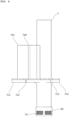
FIG. 3 is a front view of theouter pipe 7,FIG. 4 is a side view of theouter pipe 7, andFIG. 5 is a top view of theouter pipe 7. In the drawing, a flange-shaped portion 7b is connected consecutively to an outer circumference of theouter pipe 7 at a position, for example, approximately one-third of a total length from the lower end, and a plurality of (six in the present example) beam portions 7c1 to 7c6 which are formed at even intervals in the circumferential direction and extending outward in the radial direction are connected consecutively to an outer circumference of the flange-shaped portion 7b. - The beam portions 7c1 to 7c6 have a common T-shaped cross section orthogonal to the longitudinal direction thereof, and each distal end is in contact with an inner circumference of the
body 3. Since theouter pipe 7 and thebody 3 are eccentric, the lengths of the beam portions 7c1 to 7c6 are set accordingly. In the example, the beam portion 7c1 is the longest, and the beam portion 7c4 being opposed to the beam portion 7c1 interposing theouter pipe 7 is the shortest. Further, the beam portions 7c2 and 7c6 arranged on both sides of the beam portion 7c1 have equal lengths, and the beam portions 7c3 and 7c5 arranged on both sides of the beam portion 7c4 have equal lengths, wherein the beam portions 7c2 and 7c6 are longer than the beam portions 7c3 and 7c5. The spaces between the beam portions 7c1 to 7c6 serve as a flow channel. - Retaining members 7d1, 7d2, and 7d6 each having a rectangular plate shape are disposed in a manner connected consecutively to the upper surface of the beam portions 7c1, 7c2, and 7c6 and the outer circumference of the
outer pipe 7. An approximately equal gap is formed between outer edges of the retaining members 7d1, 7d2, and 7d6 and the inner circumference of thebody 3. - Next, the
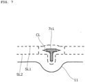
bag 11 will be described.FIG. 6 is a view illustrating a portion of a manufacturing process of thebag 11. At first, a cloth-like body FT such as felt having air permeability, water permeability, and necessary shape retaining property is cut into an approximately rectangular shape. Thereafter, the cloth-like body FT is folded back at a center line WC, and a desiccant DA (FIG. 2 ) is accommodated in the inner side thereof. Thereafter, superposed outer edges of the cloth-like body FT are sewn along double sewing lines SL1 and SL2 arranged in parallel shown by the dotted lines ofFIG. 6 , and the desiccant DA is sealed inside thebag 11. Then, a cutting line CL is formed between the sewing lines SL1 and SL2 at a center portion in the longitudinal direction of thebag 11. An opening is formed by pushing open the cutting line CL. The cutting line CL passes through thebag 11, but since the sewing line SL1 is formed on the inner side thereof, the desiccant DA within thebag 11 will not fall therethrough. -
FIG. 7 is a view illustrating a state in which thebag 11 is attached to the beam portion 7c1, and it is an enlarged view in which an end portion of the beam portion 7c1 is viewed in a longitudinal direction. During assembly, thebag 11 is arranged so as to be in contact with the outer edges of the retaining members 7d1, 7d2, and 7d6. In this state, as illustrated inFIG. 7 , the end portion of the beam portion 7c1 is arranged to pass through the opening formed by the cutting line CL of thebag 11. Thereafter, theouter pipe 7 is inserted together with thebag 11 to thebody 3. - In an initial state, the thickness of the
bag 11 is greater than a gap between the outer edges of the retaining members 7d1, 7d2, and 7d6 and the inner circumference of thebody 3, such that assembly cannot be realized in that state. Thus, the desiccant DA is moved within thebag 11, and as illustrated inFIG. 2 , threedents 11a corresponding to the retaining members 7d1, 7d2, and 7d6 are formed on thebag 11. The thickness of thebag 11 at thedents 11a is preferably 2/3 or smaller and 1/3 or greater of an average thickness of thebag 11 at areas other than thedents 11a. - The distance from the
outer pipe 7 to the outer side surface of thebag 11 is made uniform by fitting the threedents 11a to the retaining members 7d1, 7d2, and 7d6. Thereby, theouter pipe 7 may be assembled to thebody 3. In this state, thebag 11 is arranged at a position (maximum position) where the distance between the inner circumference surface of thebody 3 and the outer circumference surface of theouter pipe 7 is greatest. It is preferable for the center portion of thebag 11 to be arranged at the maximum position. In the assembled state, thebag 11 is in contact with and retained by the retaining members 7d1, 7d2, and 7d6 and the inner circumference surface of thebody 3, and a bottom portion of thebag 11 is supported on the upper surface of the beam portions 7c1, 7c2, and 7c6. Further, since the threedents 11a are fit to the retaining members 7d1, 7d2, and 7d6, relative movement of thebag 11 with respect to the circumference direction of thebody 3 may be suppressed effectively even when vibration occurs. - Further, since the distal end of the beam portion 7c1 is fit to the opening formed by opening the cutting line CL of the
bag 11, relative movement of thebag 11 in the up-down direction of thebody 3 may be suppressed even when vibration occurs. Cutting lines into which the beam portions 7c2 and 7c6 may fit may also be formed on thebag 11. Since thebag 11 is arranged in the widest space between the outer circumference of theouter pipe 7 and the inner circumference of thebody 3 while being assembled to thebody 3, blocking of the flow of refrigerant may be suppressed. - The operation of the
accumulator 1 configured as above will be described with reference toFIG. 1 . In the following description, a configuration is illustrated as an example where theaccumulator 1 is arranged between an evaporator and a compressor of the refrigeration cycle and where a gas refrigerant is generated by removing moisture contained in the refrigerant flowing from the evaporator and where the gas refrigerant is returned to the compressor. - In a state where the refrigerant is discharged from the evaporator, the refrigerant is conveyed to the
accumulator 1 through a connecting piping (not shown). The refrigerant having reached theaccumulator 1 is flown to the inner side of thebody 3 through therefrigerant inlet port 8, collides against the gas-liquid separation member 16, and is separated into a high-density liquid phase refrigerant with oil and a low-density gas phase refrigerant (gas refrigerant). - The liquid phase refrigerant with oil after being subjected to gas-liquid separation is pooled within the
body 3 by its own weight. In the process, the separation of the liquid phase refrigerant and oil advances, and oil is gathered below the liquid phase refrigerant. In this state, liquid level of the liquid phase refrigerant reaches a height position where a portion (approximately center) of thebag 11 accommodating the desiccant is immersed. Therefore, both the moisture contained in the liquid phase refrigerant and the hygroscopic moisture contained in the gas phase refrigerant are absorbed by the desiccant DA. - Meanwhile, the gas phase refrigerant having been subjected to gas-liquid separation flows in through the opening portion on the upper end of the
outer pipe 7 and descends within theouter pipe 7. Thereafter, the gas phase refrigerant turns back at the bottom portion of theouter pipe 7 and flows into theinner pipe 6, ascends within theinner pipe 6 and is guided to therefrigerant outlet port 9. In this state, oil gathered at the bottom of thebody 3 is sucked in through anoil return hole 7e, where it turns into a gas phase refrigerant containing abundant oil component, which is supplied from therefrigerant outlet port 9 through the connecting piping (not shown) to the compressor. - According to the present embodiment, the
bag 11 may be attached easily and reliably by having thebag 11 retained by the retaining members 7d1, 7d2, and 7d6 and the inner circumference surface of thebody 3 without using tying bands and the like. Further, since the distal end of the beam portion 7c1 is fit to the opening formed by opening the cutting line CL of thebag 11, relative movement of thebag 11 in the up-down direction of thebody 3 may be suppressed even when vibration occurs. Therefore, the number of components of theaccumulator 1 may be cut down, and the number of manufacturing steps may be reduced. - Since the
bag 11 is arranged above and below interposing a center position of theouter pipe 7 in the longitudinal direction, the desiccant DA that is not immersed in the liquid refrigerant is increased, such that the occurrence of a bumping phenomenon may be suppressed. Further, by formingdents 11a on thebag 11, the movement of the desiccant DA accommodated within thebag 11 is restricted. Therefore, even when theaccumulator 1 is vibrated, the crushing of the desiccant may be suppressed. -
FIG. 8 is a vertical cross-sectional view of anaccumulator 1A according to a second embodiment.FIG. 9 is a lateral cross-sectional view of theaccumulator 1A in planar view taken at line B-B ofFIG. 8 . Theaccumulator 1A differs from the above-described embodiment in that a configuration formed on an outer side of anouter pipe 7A differs. The other configurations are denoted with the same reference numbers and detailed descriptions thereof are omitted. Further, thebag 11 is also the same as the first embodiment. -
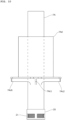
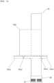
FIG. 10 is a front view of theouter pipe 7A,FIG. 11 is a side view of theouter pipe 7A, andFIG. 12 is a top view of theouter pipe 7A. As shown in the drawing, a flange-shaped portion 7Ab is connected consecutively to an outer circumference of theouter pipe 7A at a position approximately one-third of a total length from the lower end, and six beam portions 7Ac1 to 7Ac6 which are formed at even intervals in the circumferential direction and extending outward in the radial direction are connected consecutively to an outer circumference of the flange-shaped portion 7Ab. The cross-section of the flange-shaped portion 7Ab orthogonal to the longitudinal direction is T-shaped. - In the present embodiment, a plate-like retaining member is not disposed, and instead, a retaining member 7Ad having a circular pipe shape is connected consecutively to and across the upper surfaces of the
beam portions 7 Ac1 to 7Ac6. Further, a reinforcement member 7Af having a rectangular plate shape is formed in a manner connected consecutively to an upper surface of the beam portion 7Ac1, an inner circumference of the retaining member 7Ad, and an outer circumference of theouter pipe 7. A portion of the retaining member 7Ad is joined to theouter pipe 7 above the beam portion 7Ac4, and when assembled, the retaining member 7Ad is formed to be approximately coaxial with thebody 3. Therefore, an outer circumference surface of the retaining member 7Ad and an inner circumference surface of thebody 3 are approximately at even distances across the entire circumference. - During assembly, the
bag 11 is arranged to be wound around the outer circumference surface of the retaining member 7Ad with thebeam portion 7 Ac1 arranged at the center. In this state, the opening formed by opening the cutting line CL of thebag 11 is passed through the end portion of the beam portion 7Ac1. Thereafter, theouter pipe 7 is inserted together with thebag 11 to thebody 3. - Since the thickness of the
bag 11 is approximately equal to the distance between the retaining member 7Ad and thebody 3, theouter pipe 7 may be assembled to thebody 3 by sliding the outer side surface of thebag 11 against the inner circumference surface of thebody 3. In the assembled state, almost the entire surface of the outer side surface of thebag 11 is in contact with the retaining member 7Ad, almost the entire surface of the inner side surface of thebag 11 is in contact with thebody 3, and the bottom portion of thebag 11 is supported on the upper surface of the beam portions 7Ad, 7Ac2, and 7Ac6. Therefore, even when vibration occurs, the relative movement of thebag 11 with respect to the circumferential direction of thebody 3 may be suppressed. Further, since the distal end of thebeam portion 7 Ac1 is fit to the opening formed by opening the cutting line CL of thebag 11, even when vibration occurs, the relative movement of thebag 11 with respect to the up-down direction of thebody 3 may be suppressed. The upper end of thebag 11 is preferably positioned higher than the upper end of the retaining member 7Ad. - The present embodiment has been illustrated above with reference to the embodiments, but the present invention is not limited to the above-mentioned embodiments, and various modifications are enabled within the scope of the invention.
-
- 1, 1A accumulator
- 2 tank main body
- 3 body
- 4 header
- 5, 5A double pipe
- 6 inner pipe
- 7, 7A outer pipe
- 8 refrigerant inlet port
- 9 refrigerant outlet port
- 11 bag
- 20 strainer
- CL cutting line
Claims (7)
- An accumulator comprising:a body;a pipe arranged on an inner side of the body eccentrically with respect to the body;a retaining member arranged between the pipe and the body; anda bag configured to accommodate a desiccant,wherein the bag is retained by being in contact with the body and the retaining member at a position where a distance between an inner circumference surface of the body and an outer circumference surface of the pipe is greatest.
- The accumulator according to claim 1, further comprisinga plurality of beam portions configured to extend from an outer circumference of the pipe toward the body,wherein the retaining member is a plate member having a rectangular shape that is connected consecutively to at least one of the beam portions.
- The accumulator according to claim 2,
wherein a dented portion formed on the bag is fit to an edge of the plate member having a rectangular shape. - The accumulator according to claim 1, further comprisinga plurality of beam portions configured to extend from an outer circumference of the pipe toward the body,wherein the retaining member is a circular pipe-shaped member that is connected consecutively to at least one of the beam portions.
- The accumulator according to claim 4,
wherein the circular pipe-shaped member is arranged approximately coaxially with the body. - The accumulator according to any one of claims 2 to 5,
wherein the bag includes an opening formed of a cutting line, and an end portion of the beam portion is configured to fit to the opening. - The accumulator according to claim 6,
wherein the cutting line is formed between double sewing lines sewing an edge of the bag.
Applications Claiming Priority (2)
| Application Number | Priority Date | Filing Date | Title |
|---|---|---|---|
| JP2021136551A JP7475061B2 (en) | 2021-08-24 | 2021-08-24 | accumulator |
| PCT/JP2022/030861 WO2023026886A1 (en) | 2021-08-24 | 2022-08-15 | Accumulator |
Publications (2)
| Publication Number | Publication Date |
|---|---|
| EP4394283A1 true EP4394283A1 (en) | 2024-07-03 |
| EP4394283A4 EP4394283A4 (en) | 2025-08-20 |
Family
ID=85321912
Family Applications (1)
| Application Number | Title | Priority Date | Filing Date |
|---|---|---|---|
| EP22861175.2A Pending EP4394283A4 (en) | 2021-08-24 | 2022-08-15 | ACCUMULATOR |
Country Status (5)
| Country | Link |
|---|---|
| US (1) | US20240230187A1 (en) |
| EP (1) | EP4394283A4 (en) |
| JP (1) | JP7475061B2 (en) |
| CN (1) | CN117836574A (en) |
| WO (1) | WO2023026886A1 (en) |
Family Cites Families (8)
| Publication number | Priority date | Publication date | Assignee | Title |
|---|---|---|---|---|
| JPS5849017Y2 (en) * | 1980-03-07 | 1983-11-09 | 豊和工業株式会社 | Accumulator with receiver |
| JPS5783378U (en) * | 1980-11-12 | 1982-05-22 | ||
| JP5849909B2 (en) | 2012-09-07 | 2016-02-03 | 株式会社デンソー | accumulator |
| JP6175228B2 (en) * | 2012-11-22 | 2017-08-02 | 株式会社不二工機 | accumulator |
| JP6385222B2 (en) * | 2014-09-22 | 2018-09-05 | 株式会社不二工機 | accumulator |
| JP6500839B2 (en) | 2016-05-19 | 2019-04-17 | 株式会社デンソー | Accumulator and refrigeration cycle |
| JP6924438B2 (en) * | 2017-11-07 | 2021-08-25 | 株式会社不二工機 | Liquid reservoir |
| CN112013580A (en) | 2019-05-30 | 2020-12-01 | 株式会社不二工机 | Liquid storage device and assembling method thereof |
-
2021
- 2021-08-24 JP JP2021136551A patent/JP7475061B2/en active Active
-
2022
- 2022-08-15 CN CN202280056620.XA patent/CN117836574A/en active Pending
- 2022-08-15 US US18/572,640 patent/US20240230187A1/en active Pending
- 2022-08-15 EP EP22861175.2A patent/EP4394283A4/en active Pending
- 2022-08-15 WO PCT/JP2022/030861 patent/WO2023026886A1/en not_active Ceased
Also Published As
| Publication number | Publication date |
|---|---|
| CN117836574A (en) | 2024-04-05 |
| JP2023031069A (en) | 2023-03-08 |
| US20240230187A1 (en) | 2024-07-11 |
| WO2023026886A1 (en) | 2023-03-02 |
| EP4394283A4 (en) | 2025-08-20 |
| JP7475061B2 (en) | 2024-04-26 |
Similar Documents
| Publication | Publication Date | Title |
|---|---|---|
| JP6068938B2 (en) | accumulator | |
| CN104603555B (en) | reservoir | |
| JP6199590B2 (en) | accumulator | |
| JP5651431B2 (en) | Capacitor | |
| JP6385222B2 (en) | accumulator | |
| CA2168084C (en) | Refrigerant circuit accumulator and associated fabrication methods | |
| JP3163312B2 (en) | Accumulator for refrigeration cycle and method for producing the same | |
| JP5620732B2 (en) | Refrigerant tank | |
| US20240230187A1 (en) | Accumulator | |
| JP2014077606A (en) | Accumulator | |
| JP2008249242A (en) | Accumulator for refrigerating cycle | |
| EP3534092A1 (en) | Accumulator | |
| EP4394282A1 (en) | Accumulator | |
| EP4386282A1 (en) | Accumulator | |
| EP3671074B1 (en) | Accumulator | |
| US20060196219A1 (en) | Accumulator with full-flow filtering | |
| JPH10267472A (en) | Accumulator for refrigeration cycle | |
| JP6925664B2 (en) | Accumulator and its assembly method | |
| EP3293471B1 (en) | Accumulator | |
| JP2020159589A (en) | Condenser | |
| JP2009139004A (en) | accumulator | |
| CN122041443A (en) | Box (BW) | |
| EP1474640A4 (en) | Self-retaining adsorbent unit | |
| CN112013581A (en) | Liquid storage device and assembling method thereof | |
| CN120530292A (en) | Reservoir |
Legal Events
| Date | Code | Title | Description |
|---|---|---|---|
| STAA | Information on the status of an ep patent application or granted ep patent |
Free format text: STATUS: THE INTERNATIONAL PUBLICATION HAS BEEN MADE |
|
| PUAI | Public reference made under article 153(3) epc to a published international application that has entered the european phase |
Free format text: ORIGINAL CODE: 0009012 |
|
| STAA | Information on the status of an ep patent application or granted ep patent |
Free format text: STATUS: REQUEST FOR EXAMINATION WAS MADE |
|
| 17P | Request for examination filed |
Effective date: 20231220 |
|
| AK | Designated contracting states |
Kind code of ref document: A1 Designated state(s): AL AT BE BG CH CY CZ DE DK EE ES FI FR GB GR HR HU IE IS IT LI LT LU LV MC MK MT NL NO PL PT RO RS SE SI SK SM TR |
|
| DAV | Request for validation of the european patent (deleted) | ||
| DAX | Request for extension of the european patent (deleted) | ||
| A4 | Supplementary search report drawn up and despatched |
Effective date: 20250718 |
|
| RIC1 | Information provided on ipc code assigned before grant |
Ipc: F25B 43/00 20060101AFI20250714BHEP |