EP4394279A1 - Heating, ventilation, and air conditioning systems with thermoelectric generator - Google Patents
Heating, ventilation, and air conditioning systems with thermoelectric generator Download PDFInfo
- Publication number
- EP4394279A1 EP4394279A1 EP23213948.5A EP23213948A EP4394279A1 EP 4394279 A1 EP4394279 A1 EP 4394279A1 EP 23213948 A EP23213948 A EP 23213948A EP 4394279 A1 EP4394279 A1 EP 4394279A1
- Authority
- EP
- European Patent Office
- Prior art keywords
- tube
- thermoelectric generator
- working fluid
- hot
- cold
- Prior art date
- Legal status (The legal status is an assumption and is not a legal conclusion. Google has not performed a legal analysis and makes no representation as to the accuracy of the status listed.)
- Pending
Links
Images



Classifications
-
- F—MECHANICAL ENGINEERING; LIGHTING; HEATING; WEAPONS; BLASTING
- F25—REFRIGERATION OR COOLING; COMBINED HEATING AND REFRIGERATION SYSTEMS; HEAT PUMP SYSTEMS; MANUFACTURE OR STORAGE OF ICE; LIQUEFACTION SOLIDIFICATION OF GASES
- F25B—REFRIGERATION MACHINES, PLANTS OR SYSTEMS; COMBINED HEATING AND REFRIGERATION SYSTEMS; HEAT PUMP SYSTEMS
- F25B21/00—Machines, plants or systems, using electric or magnetic effects
- F25B21/02—Machines, plants or systems, using electric or magnetic effects using Peltier effect; using Nernst-Ettinghausen effect
-
- B—PERFORMING OPERATIONS; TRANSPORTING
- B60—VEHICLES IN GENERAL
- B60H—ARRANGEMENTS OF HEATING, COOLING, VENTILATING OR OTHER AIR-TREATING DEVICES SPECIALLY ADAPTED FOR PASSENGER OR GOODS SPACES OF VEHICLES
- B60H1/00—Heating, cooling or ventilating devices
- B60H1/32—Cooling devices
- B60H1/3204—Cooling devices using compression
- B60H1/3227—Cooling devices using compression characterised by the arrangement or the type of heat exchanger, e.g. condenser, evaporator
-
- F—MECHANICAL ENGINEERING; LIGHTING; HEATING; WEAPONS; BLASTING
- F24—HEATING; RANGES; VENTILATING
- F24F—AIR-CONDITIONING; AIR-HUMIDIFICATION; VENTILATION; USE OF AIR CURRENTS FOR SCREENING
- F24F5/00—Air-conditioning systems or apparatus not covered by F24F1/00 or F24F3/00, e.g. using solar heat or combined with household units such as an oven or water heater
- F24F5/0007—Air-conditioning systems or apparatus not covered by F24F1/00 or F24F3/00, e.g. using solar heat or combined with household units such as an oven or water heater cooling apparatus specially adapted for use in air-conditioning
- F24F5/001—Compression cycle type
-
- B—PERFORMING OPERATIONS; TRANSPORTING
- B60—VEHICLES IN GENERAL
- B60H—ARRANGEMENTS OF HEATING, COOLING, VENTILATING OR OTHER AIR-TREATING DEVICES SPECIALLY ADAPTED FOR PASSENGER OR GOODS SPACES OF VEHICLES
- B60H1/00—Heating, cooling or ventilating devices
- B60H1/00321—Heat exchangers for air-conditioning devices
- B60H1/00328—Heat exchangers for air-conditioning devices of the liquid-air type
-
- B—PERFORMING OPERATIONS; TRANSPORTING
- B60—VEHICLES IN GENERAL
- B60H—ARRANGEMENTS OF HEATING, COOLING, VENTILATING OR OTHER AIR-TREATING DEVICES SPECIALLY ADAPTED FOR PASSENGER OR GOODS SPACES OF VEHICLES
- B60H1/00—Heating, cooling or ventilating devices
- B60H1/00321—Heat exchangers for air-conditioning devices
- B60H1/00342—Heat exchangers for air-conditioning devices of the liquid-liquid type
-
- B—PERFORMING OPERATIONS; TRANSPORTING
- B60—VEHICLES IN GENERAL
- B60H—ARRANGEMENTS OF HEATING, COOLING, VENTILATING OR OTHER AIR-TREATING DEVICES SPECIALLY ADAPTED FOR PASSENGER OR GOODS SPACES OF VEHICLES
- B60H1/00—Heating, cooling or ventilating devices
- B60H1/00485—Valves for air-conditioning devices, e.g. thermostatic valves
-
- B—PERFORMING OPERATIONS; TRANSPORTING
- B60—VEHICLES IN GENERAL
- B60H—ARRANGEMENTS OF HEATING, COOLING, VENTILATING OR OTHER AIR-TREATING DEVICES SPECIALLY ADAPTED FOR PASSENGER OR GOODS SPACES OF VEHICLES
- B60H1/00—Heating, cooling or ventilating devices
- B60H1/00507—Details, e.g. mounting arrangements, desaeration devices
- B60H1/00557—Details of ducts or cables
- B60H1/00571—Details of ducts or cables of liquid ducts, e.g. for coolant liquids or refrigerants
-
- F—MECHANICAL ENGINEERING; LIGHTING; HEATING; WEAPONS; BLASTING
- F25—REFRIGERATION OR COOLING; COMBINED HEATING AND REFRIGERATION SYSTEMS; HEAT PUMP SYSTEMS; MANUFACTURE OR STORAGE OF ICE; LIQUEFACTION SOLIDIFICATION OF GASES
- F25B—REFRIGERATION MACHINES, PLANTS OR SYSTEMS; COMBINED HEATING AND REFRIGERATION SYSTEMS; HEAT PUMP SYSTEMS
- F25B31/00—Compressor arrangements
-
- H—ELECTRICITY
- H02—GENERATION; CONVERSION OR DISTRIBUTION OF ELECTRIC POWER
- H02N—ELECTRIC MACHINES NOT OTHERWISE PROVIDED FOR
- H02N11/00—Generators or motors not provided for elsewhere; Alleged perpetua mobilia obtained by electric or magnetic means
- H02N11/002—Generators
-
- B—PERFORMING OPERATIONS; TRANSPORTING
- B60—VEHICLES IN GENERAL
- B60H—ARRANGEMENTS OF HEATING, COOLING, VENTILATING OR OTHER AIR-TREATING DEVICES SPECIALLY ADAPTED FOR PASSENGER OR GOODS SPACES OF VEHICLES
- B60H1/00—Heating, cooling or ventilating devices
- B60H1/22—Heating, cooling or ventilating devices the heat source being other than the propulsion plant
- B60H2001/2268—Constructional features
- B60H2001/2275—Thermoelectric converters for generating electrical energy
-
- B—PERFORMING OPERATIONS; TRANSPORTING
- B60—VEHICLES IN GENERAL
- B60H—ARRANGEMENTS OF HEATING, COOLING, VENTILATING OR OTHER AIR-TREATING DEVICES SPECIALLY ADAPTED FOR PASSENGER OR GOODS SPACES OF VEHICLES
- B60H1/00—Heating, cooling or ventilating devices
- B60H1/32—Cooling devices
- B60H2001/3286—Constructional features
- B60H2001/3291—Locations with heat exchange within the refrigerant circuit itself
-
- F—MECHANICAL ENGINEERING; LIGHTING; HEATING; WEAPONS; BLASTING
- F25—REFRIGERATION OR COOLING; COMBINED HEATING AND REFRIGERATION SYSTEMS; HEAT PUMP SYSTEMS; MANUFACTURE OR STORAGE OF ICE; LIQUEFACTION SOLIDIFICATION OF GASES
- F25B—REFRIGERATION MACHINES, PLANTS OR SYSTEMS; COMBINED HEATING AND REFRIGERATION SYSTEMS; HEAT PUMP SYSTEMS
- F25B2400/00—Component parts or details not otherwise provided for in this subclass
- F25B2400/05—Compression system with heat exchange between particular parts of the system
- F25B2400/054—Compression system with heat exchange between particular parts of the system between the suction tube of the compressor and another part of the cycle
Definitions
- the present disclosure generally relates to heating, ventilation, and air conditioning systems, and more particularly relates to heating, ventilation, and air conditioning systems with a thermoelectric generator.
- HVAC heating, ventilation, and air conditioning
- a vehicle such as an aircraft, rotorcraft, automobile, train, etc.
- the components associated with the HVAC system may add additional weight to the vehicle.
- the HVAC system may consume a large quantity of electrical energy to maintain cool temperatures while the vehicle is stationary. In certain instances, the consumption of electrical energy by the HVAC system may result in a reduction of range of the batteries associated with the vehicle.
- thermoelectric generator that has a reduced weight, and a reduced consumption of electrical energy due to the electrical energy generated by the thermoelectric generator.
- the heating, ventilation, and air conditioning system includes an evaporator configured to provide a working fluid in a gaseous state at a first temperature range and a first pressure, and a compressor downstream from the evaporator.
- the compressor is configured to provide the working fluid in the gaseous state at a second temperature range and a second pressure, and the second temperature range is greater than the first temperature range and the second pressure greater than the first pressure.
- the heating, ventilation, and air conditioning system includes a first thermoelectric generator arranged between the evaporator and the compressor. A first end of the first thermoelectric generator is configured to receive the working fluid from the evaporator.
- the first thermoelectric generator has a second end opposite the first end, and the second end is configured to receive the working fluid from the compressor.
- the first thermoelectric generator is configured to generate electrical energy based on a temperature difference between the first end and the second end.
- the heating, ventilation, and air conditioning system includes a throttling valve downstream of the first thermoelectric generator in a direction of a flow of the working fluid through the heating, ventilation, and air conditioning system, and the throttling valve is configured to receive the working fluid in a third temperature range, and the third temperature range is less than the second temperature range.
- the throttling valve is fluidly coupled to the evaporator so as to be upstream from the evaporator in the direction of the flow of the working fluid through the heating, ventilation, and air conditioning system.
- the heating, ventilation, and air conditioning system includes a heat exchanger having a first tube system and a second tube system.
- the first tube system is configured to receive the working fluid from the evaporator
- the second tube system is configured to receive the working fluid from the compressor
- the first thermoelectric generator is coupled between the first tube system and the second tube system.
- the first tube system includes a first inlet configured to be fluidly coupled to the evaporator to receive the working fluid from the evaporator, a first outlet configured to be fluidly coupled to the compressor to provide the working fluid to the compressor and a first tube that connects the first inlet to the first outlet, and the first thermoelectric generator is coupled about an outer tube perimeter of the first tube.
- the second tube system includes an inner perimeter tube spaced apart from an outer perimeter tube to define a channel, the channel is defined to extend from a second inlet to a second outlet, the second inlet is configured to be fluidly coupled to the compressor to receive the working fluid, the second outlet is configured to be coupled to a throttling valve and the inner perimeter tube surrounds the first thermoelectric generator.
- the heating, ventilation, and air conditioning system includes a second thermoelectric generator coupled to an outer perimeter of the outer perimeter tube of the second tube system.
- the heating, ventilation, and air conditioning system includes an outer exchanger housing disposed about the second thermoelectric generator.
- the outer exchanger housing includes at least one fin structure.
- the heating, ventilation, and air conditioning system includes a blower configured to direct ambient air over the outer exchanger housing.
- the first tube system includes a first helical coiled tube, and the second tube system includes a second helical coiled tube, and the first thermoelectric generator is coupled about the first helical coiled tube.
- the first tube system includes a first serpentine coiled tube, and the second tube system includes a second serpentine coiled tube, and the first thermoelectric generator is coupled about the second serpentine coiled tube.
- the heating, ventilation, and air conditioning system including a heat exchanger having a first tube system and a second shell system, the first tube system including a plurality of first tubes configured to receive the working fluid from the evaporator, the second shell system configured to receive the working fluid from the compressor and to substantially surround the plurality of first tubes, and the first thermoelectric generator includes a plurality of first thermoelectric generators, with each of the plurality of first thermoelectric generators coupled about a respective one of the plurality of first tubes.
- the heating, ventilation, and air conditioning system includes a heat exchanger having a first inlet upstream from a first outlet, a second inlet upstream from a second outlet, the first inlet is configured to be directly fluidly coupled to the evaporator, the first outlet is configured to be directly fluidly coupled to the compressor, the second inlet is configured to be directly fluidly coupled to the compressor, and the second outlet is configured to be directly fluidly coupled to a throttling valve.
- the heating, ventilation, and air conditioning system includes an evaporator configured to provide a working fluid in a gaseous state at a first temperature range and a first pressure, and a compressor downstream from the evaporator and configured to provide the working fluid in the gaseous state at a second temperature range and a second pressure.
- the second temperature range is greater than the first temperature range and the second pressure is greater than the first pressure.
- the heating, ventilation, and air conditioning system includes a heat exchanger having a first tube system configured to receive the working fluid from the evaporator and a second tube system configured to receive the working fluid from the compressor such that a temperature difference exists between the first tube system and the second tube system.
- the heating, ventilation, and air conditioning system includes a first thermoelectric generator arranged between the first tube system and the second tube system, and the first thermoelectric generator is configured to generate electrical energy based on the temperature difference.
- the heating, ventilation, and air conditioning system includes a throttling valve downstream of the second tube system of the heat exchanger.
- the throttling valve is fluidly coupled to the evaporator so as to be upstream from the evaporator, the throttling valve is configured to receive the working fluid in a third temperature range from the second tube system, and the third temperature range is less than the second temperature range.
- the first tube system includes a first inlet configured to be fluidly coupled to the evaporator to receive the working fluid from the evaporator, a first outlet configured to be fluidly coupled to the compressor to provide the working fluid to the compressor, and a first tube that connects the first inlet to the first outlet, and the first thermoelectric generator is coupled about an outer tube perimeter of the first tube.
- the second tube system includes an inner perimeter tube spaced apart from an outer perimeter tube to define a channel, the channel is defined to extend from a second inlet to a second outlet, the second inlet is configured to be fluidly coupled to the compressor to receive the working fluid, the second outlet is configured to be coupled to a throttling valve and the inner perimeter tube surrounds the first thermoelectric generator.
- the heating, ventilation, and air conditioning system includes a second thermoelectric generator coupled to an outer perimeter of the outer perimeter tube.
- the heating, ventilation, and air conditioning system includes an outer exchanger housing disposed about the second thermoelectric generator and the outer exchanger housing includes at least one fin structure.
- heating, ventilation, and air conditioning system is described herein as being used onboard a vehicle, such as such as a bus, motorcycle, train, motor vehicle, marine vessel, business jet, turboprop aircraft, small helicopter or mid-size helicopter, military vehicles (e.g., Ml Tank, Joint Light Tactical Vehicle, Paladin, etc.), mobile command posts, mobile medical facilities, and the like, the various teachings of the present disclosure can be used in other applications. Further, it should be noted that many alternative or additional functional relationships or physical connections may be present in an embodiment of the present disclosure. In addition, while the figures shown herein depict an example with certain arrangements of elements, additional intervening elements, devices, features, or components may be present in an actual embodiment. It should also be understood that the drawings are merely illustrative and may not be drawn to scale.
- the term “axial” refers to a direction that is generally parallel to or coincident with an axis of rotation, axis of symmetry, or centerline of a component or components.
- the "axial" direction may refer to the direction that generally extends in parallel to the centerline between the opposite ends or faces.
- the term “axial” may be utilized with respect to components that are not cylindrical (or otherwise radially symmetric).
- the "axial" direction for a rectangular housing containing a rotating shaft may be viewed as a direction that is generally parallel to or coincident with the rotational axis of the shaft.
- radially may refer to a direction or a relationship of components with respect to a line extending outward from a shared centerline, axis, or similar reference, for example in a plane of a cylinder or disc that is perpendicular to the centerline or axis.
- components may be viewed as “radially” aligned even though one or both of the components may not be cylindrical (or otherwise radially symmetric).
- the terms “axial” and “radial” (and any derivatives) may encompass directional relationships that are other than precisely aligned with (e.g., oblique to) the true axial and radial dimensions, provided the relationship is predominantly in the respective nominal axial or radial direction.
- the term “substantially” denotes within 10% to account for manufacturing tolerances.
- the term “about” denotes within 10% to account for manufacturing tolerances.
- FIG. 1 a schematic illustration of a heating, ventilation, and air conditioning system or HVAC system 100 is shown.
- the HVAC system 100 is installed on a vehicle 99.
- the HVAC system 100 reduces a weight associated with a typical heating, ventilation, and air conditioning system as the HVAC system 100 does not include a condenser. By eliminating the condenser, the HVAC system 100 has a reduced weight and complexity.
- the HVAC system 100 generates electrical energy during the operation of the HVAC system 100, which offsets a demand the HVAC system 100 may place on a power source 102 associated with the vehicle 99, such as one or more batteries.
- the electrical energy generated by the HVAC system 100 may also be stored by the power source 102, and the power source 102 may be charged by the HVAC system 100.
- the HVAC system 100 may be electrically coupled to a downstream consumer of the vehicle 99, such as a cabin lighting system, entertainment system, etc.
- the HVAC system 100 is in electrical communication with the power source 102, and optionally, a downstream consumer 104 to supply electrical energy to the power source 102 and/or the downstream consumer 104.
- the compressor 110 raises a pressure and a temperature of the working fluid 118 received from the cold outlet 122 at the compressor inlet 120 to generate a high pressure superheated gas.
- the compressor 110 comprises any suitable compressor for raising the pressure and the temperature of the working fluid 118, including, but not limited to a positive displacement compressor, a centrifugal compressor, an axial compressor, etc.
- the working fluid 118 has a second pressure at the compressor outlet 124 of about 1 megapascal (MPa).
- the working fluid 118 at the compressor outlet 124 has a second temperature range, and in this example, the second temperature range is about 65 degrees Celsius to about 75 degrees Celsius. The second temperature range is greater than the fourth temperature range.
- the compressor 110 directs the working fluid 118 in the second temperature range and the second pressure to the hot inlet 126 of the heat exchanger 116.
- the working fluid 118 is in the gaseous state at the compressor outlet 124.
- the working fluid 118 has the second temperature range and the second pressure.
- the working fluid 118 at the hot outlet 128 is in the liquid state.
- the throttling valve 112 reduces a pressure and a temperature of the working fluid 118 as the working fluid 118 passes through the throttling valve 112 from the throttling valve inlet 130 to a throttling valve outlet 132.
- the throttling valve 112 includes, but is not limited to, a capillary tube, an automatic throttling valve, a thermostatic expansion valve, a float valve, etc.
- the working fluid 118 has a first pressure of about 130 kilopascal (kPa) to about 140 kilopascal (kPa) at the throttling valve outlet 132.
- a pump coupled to a liquid turbine generator may be used in place of the throttling valve 112 to generate electric energy.
- the electrical energy generated by the turbine generator may also be used to offset the electrical energy needed for the HVAC system 100.
- a generator pump may be used instead of the throttling valve 112.
- the generator pump may be coupled or uncoupled from the compressor 110. The generator pump would also reduce a pressure and a temperature of the working fluid 118 to about the first pressure and the first temperature range.
- the evaporator 114 includes the evaporator inlet 134, which is fluidly coupled to or in fluid communication with the throttling valve 112 to receive the liquid working fluid 118 in the first temperature range and the first pressure.
- the evaporator 114 includes an evaporator blower 136, which directs a flow of gas, such as air, through the evaporator 114.
- the evaporator blower 136 comprises any suitable fan or blower, and is in communication with the power source 102 to receive power to operate.
- the evaporator blower 136 directs the flow of the gas, such as the air, through the evaporator 114, which results in cool air 138 exiting the HVAC system 100.
- the cool air 138 may be directed, through ducting for example, to a cabin associated with the vehicle 99 or to other consumers associated with the vehicle 99.
- the working fluid 118 received at the evaporator inlet 134 flows through the evaporator 114 to an evaporator outlet 140.
- the working fluid 118 changes state from the liquid state to the gaseous state.
- the evaporator 114 includes, but is not limited to, a bare tube evaporator, a finned tube evaporator, a shell and tube evaporator, etc.
- the evaporator outlet 140 is fluidly coupled to or in fluid communication with a first, cold inlet 142 of the heat exchanger 116.
- the gaseous working fluid 118 has a pressure of about 130 kilopascal (kPa) to about 140 kilopascal (kPa) at the evaporator outlet 140.
- the gaseous working fluid 118 at the evaporator outlet 140 has the first temperature range.
- the gaseous working fluid 118 liquid in the first temperature range and the pressure is directed to the cold inlet 142 of the heat exchanger 116.
- the working fluid 118 at the cold inlet 142 has the first pressure and the first temperature range.
- the heat exchanger 116 is fluidly coupled to and in fluid communication with the compressor 110, the throttling valve 112 and the evaporator 114.
- the heat exchanger 116 is a tube-in-tube heat exchanger, which includes a first tube system or cold tube system 150, a second tube system or hot tube system 152 and an outer exchanger housing 154.
- the cold tube system 150 includes the cold inlet 142, the cold outlet 122 and a first, cold conduit, first tube or cold tube 156 that extends between the cold inlet 142 and the cold outlet 122.
- FIG. 2 a perspective cross-sectional view of the heat exchanger 116 is shown. The view of FIG. 2 is taken from the perspective of line 2-2 in FIG. 1 .
- the cold tube 156 extends through the hot tube system 152.
- the cold tube 156 is composed of a metal or metal alloy, including, but not limited to steel, aluminum, copper, etc.
- the cold tube 156 may be cast, extruded, additively manufactured, etc.
- the cold tube 156 is cylindrical, and includes a wall having an inner cold tube surface 158 opposite an outer cold tube surface 160 and a first thermoelectric generator 162.
- the inner cold tube surface 158 is in contact with the working fluid 118 as the working fluid 118 flows through the cold tube 156 from the cold inlet 142 to the cold outlet 122.
- the outer cold tube surface 160 is coupled to the first thermoelectric generator 162.
- the first thermoelectric generator 162 is arranged about a perimeter or circumference of the outer cold tube surface 160 so as to extend completely about the perimeter or circumference of the outer cold tube surface 160. It should be noted that in other embodiments, the first thermoelectric generator 162 may extend about a portion of the outer cold tube surface 160, if desired.
- the first thermoelectric generator 162 also extends about the perimeter or circumference of the outer cold tube surface 160 for a length of the outer cold tube surface 160. Generally, the first thermoelectric generator 162 extends for the length between the cold inlet 142 and the cold outlet 122 such that the first thermoelectric generator 162 is coupled about the outer cold tube surface 160 along the portion of the outer cold tube surface 160 disposed within the hot tube system 152. In one example, the first thermoelectric generator 162 extends for about 80% to 95% of the outer cold tube surface 160 that extends between the cold inlet 142 and the cold outlet 122.
- the first thermoelectric generator 162 is coupled between the outer cold tube surface 160 and a portion of the hot tube system 152 such that the first thermoelectric generator 162 is not in direct physical contact with the working fluid 118. This ensures that the working fluid 118 does not inadvertently short the first thermoelectric generator 162.
- One or more seals may be coupled to the cold tube 156 and/or the hot tube system 152 to assist in sealing the first thermoelectric generator 162 from direct contact with the working fluid 118.
- the first thermoelectric generator 162 includes at least one or a plurality of first thermoelectric generator modules 164.
- Each first thermoelectric generator module 164 is a circuit that includes an n-type semiconductor 166, a p-type semiconductor 168, a first substrate 170, a second substrate 172 and a third substrate 174.
- the n-type semiconductor 166 has negative charge carriers and the p-type semiconductor 168 has positive charge carriers.
- the n-type semiconductor 166 and the p-type semiconductor 168 are generally composed of semiconductors, such as silicon (Si) or germanium (Ge), with atomic impurities.
- the second substrate 172 and the third substrate 174 are electrically coupled in series to a resistive load 176 via a conductor, such as copper wire.
- a conductor such as copper wire.
- each of the first substrate 170, the second substrate 172 and the third substrate 174 are composed of ceramic.
- Each first thermoelectric generator module 164 is also electrically coupled to a positive terminal and a negative terminal associated with the first thermoelectric generator 162.
- the positive terminal and the negative terminal of the first thermoelectric generator 162 are each coupled to the power source 102 and/or the downstream consumer 104.
- a transformer or inverter may be coupled between the resistive load 176 and the power source 102 and/or the downstream consumer 104 to regulate a voltage flowing to the power source 102 and/or downstream consumer 104.
- the positive terminal and the negative terminal are each coupled to the first substrate 170, the second substrate 172 and the third substrate 174 via respective conductors, such as copper wire, and the positive and negative terminals extend along the hot side of the first thermoelectric generator module 164, which in this example is the side of the first thermoelectric generator module 164 coupled to the perimeter or circumference of the portion of the hot tube system 152.
- a sealing layer or an epoxy may be wrapped around the n-type semiconductor 166 and the p-type semiconductor 168 and sandwiched between the first substrate 170, the second substrate 172 and the third substrate 174.
- the positive and negative terminals may be connected in series to adjacent positive and negative terminals via a conductor, such as a copper wire.
- the hot tube 180 is cylindrical, and includes an inner perimeter tube wall 182 that is spaced apart from an outer perimeter tube wall 184 to define a channel 186.
- the inner perimeter tube wall 182 includes a first inner hot tube surface 188 opposite a second inner hot tube surface 190.
- the first inner hot tube surface 188 is coupled to the first substrate 170 of the first thermoelectric generator modules 164 of the first thermoelectric generator 162.
- the second inner hot tube surface 190 is in contact with the working fluid 118 as the working fluid 118 flows through the channel 186 of the hot tube 180 from the hot inlet 126 to the hot outlet 128.
- the outer perimeter tube wall 184 includes a first outer hot tube surface 192 opposite a second outer hot tube surface 194 and a second thermoelectric generator 196.
- the first outer hot tube surface 192 is in contact with the working fluid 118 as the working fluid 118 flows through the channel 186 of the hot tube 180 from the hot inlet 126 to the hot outlet 128.
- the second outer hot tube surface 194 is coupled to the second thermoelectric generator 196.
- the second thermoelectric generator 196 is arranged about a perimeter or circumference of the second outer hot tube surface 194 so as to extend completely about the perimeter or circumference of the second outer hot tube surface 194. It should be noted that in other embodiments, the second thermoelectric generator 196 may extend about a portion of the second outer hot tube surface 194, if desired.
- the second thermoelectric generator 196 also extends about the perimeter or circumference of the second outer hot tube surface 194 for a length of the second outer hot tube surface 194.
- the second thermoelectric generator 196 extends for the length between the hot inlet 126 and the hot outlet 128 such that the second thermoelectric generator 196 is coupled about the second outer hot tube surface 194 along the portion of the second outer hot tube surface 194 arranged opposite the outer cold tube surface 160 and opposite the second inner hot tube surface 190.
- the second thermoelectric generator 196 extends for about 80% to 95% of the second outer hot tube surface 194 that extends between the hot inlet 126 and the hot outlet 128.
- the second thermoelectric generator 196 is coupled between the second outer hot tube surface 194 and a first surface 200 of the outer exchanger housing 154 such that the second thermoelectric generator 196 is not in direct physical contact with the working fluid 118. This ensures that the working fluid 118 does not inadvertently short the second thermoelectric generator 196.
- One or more seals may be coupled to the hot tube 180 and/or the outer exchanger housing 154 to assist in sealing the second thermoelectric generator 196 from direct contact with the working fluid 118.
- the second thermoelectric generator 196 includes at least one or a plurality of second thermoelectric generator modules 198.
- each of the second thermoelectric generator modules 198 include components that are substantially similar or the same as the components of each of the first thermoelectric generator modules 164, the same reference numerals will be used to denote the same components.
- Each second thermoelectric generator module 198 is a circuit that includes the n-type semiconductor 166, the p-type semiconductor 168, the first substrate 170, the second substrate 172 and the third substrate 174.
- the first substrate 170 of each second thermoelectric generator module 198 is coupled to the second semiconductor ends 166b, 168b and couples the n-type semiconductor 166 and the p-type semiconductor 168 in series.
- the second substrate 172 and the third substrate 174 may each be coupled to the first surface 200 of the outer exchanger housing 154 via adhesives, welding, mechanical fasteners, etc.
- the second substrate 172 and the third substrate 174 are electrically coupled in series to the resistive load 176 via a conductor, such as copper wire.
- Each second thermoelectric generator module 198 is also electrically coupled to a positive terminal and a negative terminal associated with the second thermoelectric generator 196.
- the positive terminal and the negative terminal of the second thermoelectric generator 196 are each coupled to the power source 102 and/or the downstream consumer 104.
- the second substrate 172 and the third substrate 174 are electrically coupled in series to the resistive load 176.
- a temperature difference exists across each first thermoelectric generator module 164.
- the temperature difference causes electrical energy, such as a direct current, to flow in the first thermoelectric generator module 164, and the amount of direct current is directly proportional to the temperature difference.
- the first thermoelectric generator 162 also extends about the perimeter or circumference of the outer cold tube surface 660 for a length of the outer cold tube surface 660. Generally, the first thermoelectric generator 162 extends for the length between the cold inlet 142 and the cold outlet 122 such that the first thermoelectric generator 162 is coupled about the outer cold tube surface 660 along the portion of the outer cold tube surface 660 disposed within the hot tube system 152. In one example, the first thermoelectric generator 162 extends for about 80% to 95% of the outer cold tube surface 660 that extends between the cold inlet 142 and the cold outlet 122.
- the outer exchanger housing 154 surrounds the hot tube 780.
- the outer exchanger housing 154 includes the first surface 200 and the opposite second surface 204.
- the second surface 204 includes the fin structure 206.
- the fin structure 206 assists in providing additional cooling to the outer exchanger housing 154, which assists in maintaining a temperature difference between the outer exchanger housing 154 and the hot tube 780.
- the heat exchanger 716 may also include the optional fan or blower 220.
- the outer exchanger housing 154 is coupled about the outer perimeter tube wall 184 and is coupled to the second thermoelectric generator 196.
- the first thermoelectric generator 162 is coupled to the outer cold tube surface 160 of each of the cold tubes 356.
- the hot shell 380 is coupled about the cold tubes 356.
- the second thermoelectric generator 196 is coupled to the hot shell 380.
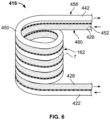
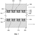
- the first thermoelectric generator 162 is coupled to the outer cold tube surface 160 of the cold coiled tube 456.
- the hot coiled tube 480 is intertwined or interleaved with the cold coiled tube 456 such that the hot coiled tube 480 is coupled to the first thermoelectric generator 162.
- the working fluid 118 flows as the low pressure and low temperature gas from the evaporator 114 to the cold tube system 150, 350, 450, 550 of the heat exchanger 116, 316, 416, 516, 616, 716.
- the working fluid 118 flows through the cold tube system 150, 350, 450, 550 of the heat exchanger 116, 316, 416, 516, 616, 716 and exits the cold tube system 150, 350, 450, 550 as the low pressure gas, with the fourth temperature range.
Landscapes
- Engineering & Computer Science (AREA)
- Mechanical Engineering (AREA)
- Physics & Mathematics (AREA)
- Thermal Sciences (AREA)
- General Engineering & Computer Science (AREA)
- Life Sciences & Earth Sciences (AREA)
- Sustainable Development (AREA)
- Chemical & Material Sciences (AREA)
- Combustion & Propulsion (AREA)
- Heat-Exchange Devices With Radiators And Conduit Assemblies (AREA)
Abstract
Description
- The present disclosure generally relates to heating, ventilation, and air conditioning systems, and more particularly relates to heating, ventilation, and air conditioning systems with a thermoelectric generator.
- Generally, heating, ventilation, and air conditioning ("HVAC") systems are used to regulate temperature within an enclosed area, such as a building, vehicle, etc. In the example of HVAC systems for a vehicle, such as an aircraft, rotorcraft, automobile, train, etc., the components associated with the HVAC system may add additional weight to the vehicle. Further, the HVAC system may consume a large quantity of electrical energy to maintain cool temperatures while the vehicle is stationary. In certain instances, the consumption of electrical energy by the HVAC system may result in a reduction of range of the batteries associated with the vehicle.
- Accordingly, it is desirable to provide a heating, ventilation, and air conditioning system with a thermoelectric generator that has a reduced weight, and a reduced consumption of electrical energy due to the electrical energy generated by the thermoelectric generator. Furthermore, other desirable features and characteristics of the present invention will become apparent from the subsequent detailed description and the appended claims, taken in conjunction with the accompanying drawings and the foregoing technical field and background.
- According to various embodiments, provided is a heating, ventilation, and air conditioning system. The heating, ventilation, and air conditioning system includes an evaporator configured to provide a working fluid in a gaseous state at a first temperature range and a first pressure, and a compressor downstream from the evaporator. The compressor is configured to provide the working fluid in the gaseous state at a second temperature range and a second pressure, and the second temperature range is greater than the first temperature range and the second pressure greater than the first pressure. The heating, ventilation, and air conditioning system includes a first thermoelectric generator arranged between the evaporator and the compressor. A first end of the first thermoelectric generator is configured to receive the working fluid from the evaporator. The first thermoelectric generator has a second end opposite the first end, and the second end is configured to receive the working fluid from the compressor. The first thermoelectric generator is configured to generate electrical energy based on a temperature difference between the first end and the second end.
- The heating, ventilation, and air conditioning system includes a throttling valve downstream of the first thermoelectric generator in a direction of a flow of the working fluid through the heating, ventilation, and air conditioning system, and the throttling valve is configured to receive the working fluid in a third temperature range, and the third temperature range is less than the second temperature range. The throttling valve is fluidly coupled to the evaporator so as to be upstream from the evaporator in the direction of the flow of the working fluid through the heating, ventilation, and air conditioning system. The heating, ventilation, and air conditioning system includes a heat exchanger having a first tube system and a second tube system. The first tube system is configured to receive the working fluid from the evaporator, the second tube system is configured to receive the working fluid from the compressor, and the first thermoelectric generator is coupled between the first tube system and the second tube system. The first tube system includes a first inlet configured to be fluidly coupled to the evaporator to receive the working fluid from the evaporator, a first outlet configured to be fluidly coupled to the compressor to provide the working fluid to the compressor and a first tube that connects the first inlet to the first outlet, and the first thermoelectric generator is coupled about an outer tube perimeter of the first tube. The second tube system includes an inner perimeter tube spaced apart from an outer perimeter tube to define a channel, the channel is defined to extend from a second inlet to a second outlet, the second inlet is configured to be fluidly coupled to the compressor to receive the working fluid, the second outlet is configured to be coupled to a throttling valve and the inner perimeter tube surrounds the first thermoelectric generator. The heating, ventilation, and air conditioning system includes a second thermoelectric generator coupled to an outer perimeter of the outer perimeter tube of the second tube system. The heating, ventilation, and air conditioning system includes an outer exchanger housing disposed about the second thermoelectric generator. The outer exchanger housing includes at least one fin structure. The heating, ventilation, and air conditioning system includes a blower configured to direct ambient air over the outer exchanger housing. The first tube system includes a first helical coiled tube, and the second tube system includes a second helical coiled tube, and the first thermoelectric generator is coupled about the first helical coiled tube. The first tube system includes a first serpentine coiled tube, and the second tube system includes a second serpentine coiled tube, and the first thermoelectric generator is coupled about the second serpentine coiled tube. The heating, ventilation, and air conditioning system including a heat exchanger having a first tube system and a second shell system, the first tube system including a plurality of first tubes configured to receive the working fluid from the evaporator, the second shell system configured to receive the working fluid from the compressor and to substantially surround the plurality of first tubes, and the first thermoelectric generator includes a plurality of first thermoelectric generators, with each of the plurality of first thermoelectric generators coupled about a respective one of the plurality of first tubes. The heating, ventilation, and air conditioning system includes a heat exchanger having a first inlet upstream from a first outlet, a second inlet upstream from a second outlet, the first inlet is configured to be directly fluidly coupled to the evaporator, the first outlet is configured to be directly fluidly coupled to the compressor, the second inlet is configured to be directly fluidly coupled to the compressor, and the second outlet is configured to be directly fluidly coupled to a throttling valve.
- Also provided is a heating, ventilation, and air conditioning system. The heating, ventilation, and air conditioning system includes an evaporator configured to provide a working fluid in a gaseous state at a first temperature range and a first pressure, and a compressor downstream from the evaporator and configured to provide the working fluid in the gaseous state at a second temperature range and a second pressure. The second temperature range is greater than the first temperature range and the second pressure is greater than the first pressure. The heating, ventilation, and air conditioning system includes a heat exchanger having a first tube system configured to receive the working fluid from the evaporator and a second tube system configured to receive the working fluid from the compressor such that a temperature difference exists between the first tube system and the second tube system. The heating, ventilation, and air conditioning system includes a first thermoelectric generator arranged between the first tube system and the second tube system, and the first thermoelectric generator is configured to generate electrical energy based on the temperature difference.
- The heating, ventilation, and air conditioning system includes a throttling valve downstream of the second tube system of the heat exchanger. The throttling valve is fluidly coupled to the evaporator so as to be upstream from the evaporator, the throttling valve is configured to receive the working fluid in a third temperature range from the second tube system, and the third temperature range is less than the second temperature range. The first tube system includes a first inlet configured to be fluidly coupled to the evaporator to receive the working fluid from the evaporator, a first outlet configured to be fluidly coupled to the compressor to provide the working fluid to the compressor, and a first tube that connects the first inlet to the first outlet, and the first thermoelectric generator is coupled about an outer tube perimeter of the first tube. The second tube system includes an inner perimeter tube spaced apart from an outer perimeter tube to define a channel, the channel is defined to extend from a second inlet to a second outlet, the second inlet is configured to be fluidly coupled to the compressor to receive the working fluid, the second outlet is configured to be coupled to a throttling valve and the inner perimeter tube surrounds the first thermoelectric generator. The heating, ventilation, and air conditioning system includes a second thermoelectric generator coupled to an outer perimeter of the outer perimeter tube. The heating, ventilation, and air conditioning system includes an outer exchanger housing disposed about the second thermoelectric generator and the outer exchanger housing includes at least one fin structure.
- The exemplary embodiments will hereinafter be described in conjunction with the following drawing figures, wherein like numerals denote like elements, and wherein:
-
FIG. 1 is a simplified schematic illustration of a heating, ventilation, and air conditioning ("HVAC") system associated with a vehicle in accordance with the various teachings of the present disclosure; -
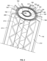
FIG. 2 is a perspective partially cross-sectional detail view of a heat exchanger associated with the HVAC system ofFIG. 1 , taken from the perspective of line 2-2 inFIG. 1 ; -
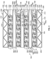
FIG. 3 is a cross-sectional view of the heat exchanger ofFIG. 2 , taken along line 3-3 ofFIG. 2 ; -
FIG. 4 is a perspective view of another exemplary heat exchanger for use with the HVAC system ofFIG. 1 in accordance with the various teachings of the present disclosure; -
FIG. 5 is a cross-sectional view of the heat exchanger ofFIG. 4 , taken along line 5-5 ofFIG. 4 ; -
FIG. 6 is a perspective view of another exemplary heat exchanger for use with the HVAC system ofFIG. 1 in accordance with the various teachings of the present disclosure; -
FIG. 7 is a detail cross-sectional view of the heat exchanger ofFIG. 6 , taken at 7 ofFIG. 6 ; -
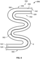
FIG. 8 is a perspective view of another exemplary heat exchanger for use with the HVAC system ofFIG. 1 in accordance with the various teachings of the present disclosure; -
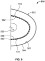
FIG. 9 is a detail cross-sectional view of the heat exchanger ofFIG. 8 , taken at 9 ofFIG. 8 ; -
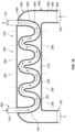
FIG. 10 is a cross-sectional view of another exemplary heat exchanger for use with the HVAC system ofFIG. 1 in accordance with the various teachings of the present disclosure; and -
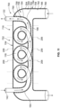
FIG. 11 is a cross-sectional view of another exemplary heat exchanger for use with the HVAC system ofFIG. 1 in accordance with the various teachings of the present disclosure. - The following detailed description is merely exemplary in nature and is not intended to limit the application and uses. Furthermore, there is no intention to be bound by any expressed or implied theory presented in the preceding technical field, background, brief summary or the following detailed description. In addition, those skilled in the art will appreciate that embodiments of the present disclosure may be practiced in conjunction with any type of heating, ventilation, and air conditioning system, and the use of the heating, ventilation, and air conditioning system with a vehicle described herein is merely one exemplary embodiment according to the present disclosure. In addition, while the heating, ventilation, and air conditioning system is described herein as being used onboard a vehicle, such as such as a bus, motorcycle, train, motor vehicle, marine vessel, business jet, turboprop aircraft, small helicopter or mid-size helicopter, military vehicles (e.g., Ml Tank, Joint Light Tactical Vehicle, Paladin, etc.), mobile command posts, mobile medical facilities, and the like, the various teachings of the present disclosure can be used in other applications. Further, it should be noted that many alternative or additional functional relationships or physical connections may be present in an embodiment of the present disclosure. In addition, while the figures shown herein depict an example with certain arrangements of elements, additional intervening elements, devices, features, or components may be present in an actual embodiment. It should also be understood that the drawings are merely illustrative and may not be drawn to scale.
- As used herein, the term "axial" refers to a direction that is generally parallel to or coincident with an axis of rotation, axis of symmetry, or centerline of a component or components. For example, in a cylinder or disc with a centerline and generally circular ends or opposing faces, the "axial" direction may refer to the direction that generally extends in parallel to the centerline between the opposite ends or faces. In certain instances, the term "axial" may be utilized with respect to components that are not cylindrical (or otherwise radially symmetric). For example, the "axial" direction for a rectangular housing containing a rotating shaft may be viewed as a direction that is generally parallel to or coincident with the rotational axis of the shaft. Furthermore, the term "radially" as used herein may refer to a direction or a relationship of components with respect to a line extending outward from a shared centerline, axis, or similar reference, for example in a plane of a cylinder or disc that is perpendicular to the centerline or axis. In certain instances, components may be viewed as "radially" aligned even though one or both of the components may not be cylindrical (or otherwise radially symmetric). Furthermore, the terms "axial" and "radial" (and any derivatives) may encompass directional relationships that are other than precisely aligned with (e.g., oblique to) the true axial and radial dimensions, provided the relationship is predominantly in the respective nominal axial or radial direction. As used herein, the term "substantially" denotes within 10% to account for manufacturing tolerances. Also, as used herein, the term "about" denotes within 10% to account for manufacturing tolerances.
- With reference to
FIG. 1 , a schematic illustration of a heating, ventilation, and air conditioning system orHVAC system 100 is shown. In one example, theHVAC system 100 is installed on avehicle 99. As will be discussed, theHVAC system 100 reduces a weight associated with a typical heating, ventilation, and air conditioning system as theHVAC system 100 does not include a condenser. By eliminating the condenser, theHVAC system 100 has a reduced weight and complexity. In addition, theHVAC system 100 generates electrical energy during the operation of theHVAC system 100, which offsets a demand theHVAC system 100 may place on apower source 102 associated with thevehicle 99, such as one or more batteries. The electrical energy generated by theHVAC system 100 may also be stored by thepower source 102, and thepower source 102 may be charged by theHVAC system 100. Alternatively, theHVAC system 100 may be electrically coupled to a downstream consumer of thevehicle 99, such as a cabin lighting system, entertainment system, etc. Thus, generally, theHVAC system 100 is in electrical communication with thepower source 102, and optionally, adownstream consumer 104 to supply electrical energy to thepower source 102 and/or thedownstream consumer 104. - With continued reference to
FIG. 1 , in this example, theHVAC system 100 includes acompressor 110, a throttlingvalve 112, anevaporator 114 and aheat exchanger 116. Although not illustrated herein, a housing may enclose all or a portion of theHVAC system 100. Generally, a single workingfluid 118 is contained within and employed by theHVAC system 100. Thecompressor 110, the throttlingvalve 112, theevaporator 114 and theheat exchanger 116 may be fluidly coupled together or in fluid communication as described below via one or more conduits, hoses, pipes, etc. and the associated fittings that enable the workingfluid 118 to flow through theHVAC system 100. In one example, the workingfluid 118 is a refrigerant, including, but not limited to refrigerant 134a. - The
compressor 110 is in fluid communication with theheat exchanger 116. In this example, thecompressor 110 includes acompressor inlet 120 fluidly coupled to or in fluid communication with a first,cold outlet 122 of theheat exchanger 116 such that thecompressor 110 is downstream from thecold outlet 122 of theheat exchanger 116. Thecompressor 110 also includes acompressor outlet 124 fluidly coupled to or in fluid communication with a second,hot inlet 126 of theheat exchanger 116 such that thecompressor 110 is upstream from thehot inlet 126 of theheat exchanger 116. Generally, thecompressor 110 receives the workingfluid 118 as a low pressure gas from thecold outlet 122 of theheat exchanger 116. The workingfluid 118 is in a gaseous state at thecompressor inlet 120. In one example, the workingfluid 118 has a fourth pressure at thecold outlet 122 of theheat exchanger 116 of about 130 kilopascal (kPa) to about 140 kilopascal (kPa). The workingfluid 118 at thecold outlet 122 of theheat exchanger 116 has a fourth temperature, and in this example, the fourth temperature range is about negative 10 degrees Celsius to about negative 30 degrees Celsius. - The
compressor 110 raises a pressure and a temperature of the workingfluid 118 received from thecold outlet 122 at thecompressor inlet 120 to generate a high pressure superheated gas. Thecompressor 110 comprises any suitable compressor for raising the pressure and the temperature of the workingfluid 118, including, but not limited to a positive displacement compressor, a centrifugal compressor, an axial compressor, etc. In one example, the workingfluid 118 has a second pressure at thecompressor outlet 124 of about 1 megapascal (MPa). The workingfluid 118 at thecompressor outlet 124 has a second temperature range, and in this example, the second temperature range is about 65 degrees Celsius to about 75 degrees Celsius. The second temperature range is greater than the fourth temperature range. Thecompressor 110 directs the workingfluid 118 in the second temperature range and the second pressure to thehot inlet 126 of theheat exchanger 116. The workingfluid 118 is in the gaseous state at thecompressor outlet 124. Thus, at the hot inlet, the workingfluid 118 has the second temperature range and the second pressure. - The throttling
valve 112 is fluidly coupled to or in fluid communication with a second,hot outlet 128 of theheat exchanger 116. The throttlingvalve 112 receives the workingfluid 118 from thehot outlet 128 at a throttlingvalve inlet 130. Generally, the throttlingvalve 112 receives the workingfluid 118 as a high pressure cooled liquid from thehot outlet 128 of theheat exchanger 116. In one example, the workingfluid 118 has a third pressure at thehot outlet 128 of theheat exchanger 116 of about 1 megapascal (MPa). The workingfluid 118 at thehot outlet 128 of theheat exchanger 116 has a third temperature range, and in this example, the third temperature range is about 25 degrees Celsius to about 35 degrees Celsius. The workingfluid 118 at thehot outlet 128 is in the liquid state. The throttlingvalve 112 reduces a pressure and a temperature of the workingfluid 118 as the workingfluid 118 passes through the throttlingvalve 112 from the throttlingvalve inlet 130 to a throttlingvalve outlet 132. In one example, the throttlingvalve 112 includes, but is not limited to, a capillary tube, an automatic throttling valve, a thermostatic expansion valve, a float valve, etc. Generally, the workingfluid 118 has a first pressure of about 130 kilopascal (kPa) to about 140 kilopascal (kPa) at the throttlingvalve outlet 132. The workingfluid 118 at the throttlingvalve outlet 132 has a first temperature range, and in this example, the first temperature range is about negative 15 degrees Celsius to about negative 25 degrees Celsius. The first temperature range is less than the second temperature range and the third temperature range. The throttlingvalve 112 directs the workingfluid 118 in the first temperature range and the first pressure to anevaporator inlet 134 of theevaporator 114. The workingfluid 118 at the throttlingvalve outlet 132 is in the liquid state. It should be noted that while the use of the throttlingvalve 112 is described and illustrated herein, a liquid turbine generator may be used in place of the throttlingvalve 112. In addition, in other embodiments, a pump coupled to a liquid turbine generator may be used in place of the throttlingvalve 112 to generate electric energy. The electrical energy generated by the turbine generator may also be used to offset the electrical energy needed for theHVAC system 100. In other embodiments, a generator pump may be used instead of the throttlingvalve 112. The generator pump may be coupled or uncoupled from thecompressor 110. The generator pump would also reduce a pressure and a temperature of the workingfluid 118 to about the first pressure and the first temperature range. - The
evaporator 114 includes theevaporator inlet 134, which is fluidly coupled to or in fluid communication with the throttlingvalve 112 to receive theliquid working fluid 118 in the first temperature range and the first pressure. In this example, theevaporator 114 includes anevaporator blower 136, which directs a flow of gas, such as air, through theevaporator 114. Theevaporator blower 136 comprises any suitable fan or blower, and is in communication with thepower source 102 to receive power to operate. Theevaporator blower 136 directs the flow of the gas, such as the air, through theevaporator 114, which results incool air 138 exiting theHVAC system 100. Thecool air 138 may be directed, through ducting for example, to a cabin associated with thevehicle 99 or to other consumers associated with thevehicle 99. The workingfluid 118 received at theevaporator inlet 134 flows through theevaporator 114 to anevaporator outlet 140. As the workingfluid 118 flows through theevaporator 114, the workingfluid 118 changes state from the liquid state to the gaseous state. Theevaporator 114 includes, but is not limited to, a bare tube evaporator, a finned tube evaporator, a shell and tube evaporator, etc. Theevaporator outlet 140 is fluidly coupled to or in fluid communication with a first,cold inlet 142 of theheat exchanger 116. Generally, the gaseous workingfluid 118 has a pressure of about 130 kilopascal (kPa) to about 140 kilopascal (kPa) at theevaporator outlet 140. The gaseous workingfluid 118 at theevaporator outlet 140 has the first temperature range. The gaseous workingfluid 118 liquid in the first temperature range and the pressure is directed to thecold inlet 142 of theheat exchanger 116. Thus, the workingfluid 118 at thecold inlet 142 has the first pressure and the first temperature range. - The
heat exchanger 116 is fluidly coupled to and in fluid communication with thecompressor 110, the throttlingvalve 112 and theevaporator 114. In one example, theheat exchanger 116 is a tube-in-tube heat exchanger, which includes a first tube system orcold tube system 150, a second tube system orhot tube system 152 and anouter exchanger housing 154. Thecold tube system 150 includes thecold inlet 142, thecold outlet 122 and a first, cold conduit, first tube orcold tube 156 that extends between thecold inlet 142 and thecold outlet 122. With reference toFIG. 2 , a perspective cross-sectional view of theheat exchanger 116 is shown. The view ofFIG. 2 is taken from the perspective of line 2-2 inFIG. 1 . Thecold tube 156 extends through thehot tube system 152. Thecold tube 156 is composed of a metal or metal alloy, including, but not limited to steel, aluminum, copper, etc. Thecold tube 156 may be cast, extruded, additively manufactured, etc. In this example, thecold tube 156 is cylindrical, and includes a wall having an innercold tube surface 158 opposite an outercold tube surface 160 and a firstthermoelectric generator 162. The innercold tube surface 158 is in contact with the workingfluid 118 as the workingfluid 118 flows through thecold tube 156 from thecold inlet 142 to thecold outlet 122. The outercold tube surface 160 is coupled to the firstthermoelectric generator 162. In this example, the firstthermoelectric generator 162 is arranged about a perimeter or circumference of the outercold tube surface 160 so as to extend completely about the perimeter or circumference of the outercold tube surface 160. It should be noted that in other embodiments, the firstthermoelectric generator 162 may extend about a portion of the outercold tube surface 160, if desired. - The first
thermoelectric generator 162, in this example, also extends about the perimeter or circumference of the outercold tube surface 160 for a length of the outercold tube surface 160. Generally, the firstthermoelectric generator 162 extends for the length between thecold inlet 142 and thecold outlet 122 such that the firstthermoelectric generator 162 is coupled about the outercold tube surface 160 along the portion of the outercold tube surface 160 disposed within thehot tube system 152. In one example, the firstthermoelectric generator 162 extends for about 80% to 95% of the outercold tube surface 160 that extends between thecold inlet 142 and thecold outlet 122. The firstthermoelectric generator 162 is coupled between the outercold tube surface 160 and a portion of thehot tube system 152 such that the firstthermoelectric generator 162 is not in direct physical contact with the workingfluid 118. This ensures that the workingfluid 118 does not inadvertently short the firstthermoelectric generator 162. One or more seals may be coupled to thecold tube 156 and/or thehot tube system 152 to assist in sealing the firstthermoelectric generator 162 from direct contact with the workingfluid 118. - In one example, with reference to
FIG. 3 , the firstthermoelectric generator 162 includes at least one or a plurality of firstthermoelectric generator modules 164. Each firstthermoelectric generator module 164 is a circuit that includes an n-type semiconductor 166, a p-type semiconductor 168, afirst substrate 170, asecond substrate 172 and athird substrate 174. The n-type semiconductor 166 has negative charge carriers and the p-type semiconductor 168 has positive charge carriers. The n-type semiconductor 166 and the p-type semiconductor 168 are generally composed of semiconductors, such as silicon (Si) or germanium (Ge), with atomic impurities. Each of the n-type semiconductor 166 and the p-type semiconductor 168 have a respectivefirst semiconductor end second semiconductor end first substrate 170 is coupled to the second semiconductor ends 166b, 168b and couples the n-type semiconductor 166 and the p-type semiconductor 168 in series. Thefirst substrate 170 is also coupled to the portion of thehot tube system 152 about a perimeter or circumference of the portion of thehot tube system 152. Thefirst substrate 170 may be coupled to the portion of thehot tube system 152 via adhesives, welding, mechanical fasteners, etc. Thefirst substrate 170 forms an end of the firstthermoelectric generator module 164. Thesecond substrate 172 is coupled to thefirst semiconductor end 166a of the n-type semiconductor 166 and to the outercold tube surface 160 about the perimeter or circumference of the outercold tube surface 160. Thethird substrate 174 is coupled to thefirst semiconductor end 168a of the p-type semiconductor 168 and the outercold tube surface 160 about the perimeter or circumference of the outercold tube surface 160. Thesecond substrate 172 and thethird substrate 174 may each be coupled to the outercold tube surface 160 via adhesives, welding, mechanical fasteners, etc. Thesecond substrate 172 and thethird substrate 174 form an end of the firstthermoelectric generator module 164, which is opposite the end formed by thefirst substrate 170. Thesecond substrate 172 and thethird substrate 174 are electrically coupled in series to aresistive load 176 via a conductor, such as copper wire. In one example, each of thefirst substrate 170, thesecond substrate 172 and thethird substrate 174 are composed of ceramic. Each firstthermoelectric generator module 164 is also electrically coupled to a positive terminal and a negative terminal associated with the firstthermoelectric generator 162. The positive terminal and the negative terminal of the firstthermoelectric generator 162 are each coupled to thepower source 102 and/or thedownstream consumer 104. In certain examples, a transformer or inverter may be coupled between theresistive load 176 and thepower source 102 and/or thedownstream consumer 104 to regulate a voltage flowing to thepower source 102 and/ordownstream consumer 104. In one example, the positive terminal and the negative terminal are each coupled to thefirst substrate 170, thesecond substrate 172 and thethird substrate 174 via respective conductors, such as copper wire, and the positive and negative terminals extend along the hot side of the firstthermoelectric generator module 164, which in this example is the side of the firstthermoelectric generator module 164 coupled to the perimeter or circumference of the portion of thehot tube system 152. In addition, a sealing layer or an epoxy may be wrapped around the n-type semiconductor 166 and the p-type semiconductor 168 and sandwiched between thefirst substrate 170, thesecond substrate 172 and thethird substrate 174. The positive and negative terminals may be connected in series to adjacent positive and negative terminals via a conductor, such as a copper wire. - Generally, each of the first
thermoelectric generator modules 164 employ the Seeback effect to generate electrical energy, such as a direct current, based on a temperature difference between thecold tube 156 and a portion of thehot tube system 152. Briefly, as thefirst substrate 170 is coupled to or in communication with the portion of thehot tube system 152, and thesecond substrate 172 and thethird substrate 174 are coupled to or in communication with the outercold tube surface 160, a temperature difference exists across each firstthermoelectric generator module 164. The temperature difference causes direct current to flow in the firstthermoelectric generator module 164, and the amount of direct current is directly proportional to the temperature difference. In one example, each of the firstthermoelectric generator modules 164 are coupled about an entirety of the perimeter or circumference of the outercold tube surface 160, and adjacent firstthermoelectric generator modules 164 are electrically coupled together in series along the length of thecold tube 156. Thus, in this example, the firstthermoelectric generator modules 164 are arranged circumferentially in rows along the length of thecold tube 156 such that the n-type semiconductor 166 of one of the firstthermoelectric generator modules 164 is adjacent to the p-type semiconductor 168 of another one of the firstthermoelectric generator modules 164. In addition, by being arranged in rows along the perimeter or circumference of the outercold tube surface 160, thesecond substrates 172 and thethird substrates 174 of each of the firstthermoelectric generator modules 164 cooperate to form an end of the firstthermoelectric generator 162, while thefirst substrates 170 of each of the firstthermoelectric generator modules 164 cooperate to form an opposite end of the firstthermoelectric generator 162. - With reference back to
FIG. 1 , thehot tube system 152 includes thehot inlet 126, thehot outlet 128 and a second, hot conduit or second,hot tube 180 that extends between thehot inlet 126 and thehot outlet 128. With reference toFIG. 2 , thehot tube 180 surrounds a majority of thecold tube system 150 such that thecold tube system 150 extends through thehot tube 180 between thehot inlet 126 and thehot outlet 128. Thehot tube 180 is composed of a metal or metal alloy, including, but not limited to steel, aluminum, copper, etc. Thehot tube 180 may be cast, extruded, additively manufactured, etc. In this example, thehot tube 180 is cylindrical, and includes an innerperimeter tube wall 182 that is spaced apart from an outerperimeter tube wall 184 to define achannel 186. The innerperimeter tube wall 182 includes a first innerhot tube surface 188 opposite a second innerhot tube surface 190. The first innerhot tube surface 188 is coupled to thefirst substrate 170 of the firstthermoelectric generator modules 164 of the firstthermoelectric generator 162. The second innerhot tube surface 190 is in contact with the workingfluid 118 as the workingfluid 118 flows through thechannel 186 of thehot tube 180 from thehot inlet 126 to thehot outlet 128. The outerperimeter tube wall 184 includes a first outerhot tube surface 192 opposite a second outerhot tube surface 194 and a secondthermoelectric generator 196. The first outerhot tube surface 192 is in contact with the workingfluid 118 as the workingfluid 118 flows through thechannel 186 of thehot tube 180 from thehot inlet 126 to thehot outlet 128. The second outerhot tube surface 194 is coupled to the secondthermoelectric generator 196. In this example, the secondthermoelectric generator 196 is arranged about a perimeter or circumference of the second outerhot tube surface 194 so as to extend completely about the perimeter or circumference of the second outerhot tube surface 194. It should be noted that in other embodiments, the secondthermoelectric generator 196 may extend about a portion of the second outerhot tube surface 194, if desired. - The second
thermoelectric generator 196, in this example, also extends about the perimeter or circumference of the second outerhot tube surface 194 for a length of the second outerhot tube surface 194. Generally, the secondthermoelectric generator 196 extends for the length between thehot inlet 126 and thehot outlet 128 such that the secondthermoelectric generator 196 is coupled about the second outerhot tube surface 194 along the portion of the second outerhot tube surface 194 arranged opposite the outercold tube surface 160 and opposite the second innerhot tube surface 190. In one example, the secondthermoelectric generator 196 extends for about 80% to 95% of the second outerhot tube surface 194 that extends between thehot inlet 126 and thehot outlet 128. The secondthermoelectric generator 196 is coupled between the second outerhot tube surface 194 and afirst surface 200 of theouter exchanger housing 154 such that the secondthermoelectric generator 196 is not in direct physical contact with the workingfluid 118. This ensures that the workingfluid 118 does not inadvertently short the secondthermoelectric generator 196. One or more seals may be coupled to thehot tube 180 and/or theouter exchanger housing 154 to assist in sealing the secondthermoelectric generator 196 from direct contact with the workingfluid 118. - In one example, with reference to
FIG. 3 , the secondthermoelectric generator 196 includes at least one or a plurality of secondthermoelectric generator modules 198. As each of the secondthermoelectric generator modules 198 include components that are substantially similar or the same as the components of each of the firstthermoelectric generator modules 164, the same reference numerals will be used to denote the same components. Each secondthermoelectric generator module 198 is a circuit that includes the n-type semiconductor 166, the p-type semiconductor 168, thefirst substrate 170, thesecond substrate 172 and thethird substrate 174. Thefirst substrate 170 of each secondthermoelectric generator module 198 is coupled to the second semiconductor ends 166b, 168b and couples the n-type semiconductor 166 and the p-type semiconductor 168 in series. Thefirst substrate 170 of each secondthermoelectric generator module 198 is also coupled to the second outerhot tube surface 194 about a perimeter or circumference of the second outerhot tube surface 194. Thefirst substrate 170 may be coupled to the second outerhot tube surface 194 via adhesives, welding, mechanical fasteners, etc. Thesecond substrate 172 of each secondthermoelectric generator module 198 is coupled to thefirst semiconductor end 166a of the n-type semiconductor 166 and to thefirst surface 200 of theouter exchanger housing 154 about an inner perimeter or circumference of thefirst surface 200. Thethird substrate 174 of each secondthermoelectric generator module 198 is coupled to thefirst semiconductor end 168a of the p-type semiconductor 168 and thefirst surface 200 of theouter exchanger housing 154 about the inner perimeter or circumference of thefirst surface 200. Thesecond substrate 172 and thethird substrate 174 may each be coupled to thefirst surface 200 of theouter exchanger housing 154 via adhesives, welding, mechanical fasteners, etc. Thesecond substrate 172 and thethird substrate 174 are electrically coupled in series to theresistive load 176 via a conductor, such as copper wire. Each secondthermoelectric generator module 198 is also electrically coupled to a positive terminal and a negative terminal associated with the secondthermoelectric generator 196. The positive terminal and the negative terminal of the secondthermoelectric generator 196 are each coupled to thepower source 102 and/or thedownstream consumer 104. In certain examples, a transformer or inverter may be coupled between theresistive load 176 and thepower source 102 and/or thedownstream consumer 104 to regulate a voltage flowing to thepower source 102 and/ordownstream consumer 104. In one example, the positive terminal and the negative terminal are each coupled to thefirst substrate 170, thesecond substrate 172 and thethird substrate 174 via respective conductors, such as copper wire, and the positive and negative terminals extend along the hot side of the secondthermoelectric generator modules 198, which in this example is the side of the secondthermoelectric generator modules 198 coupled to the perimeter or circumference of the second outerhot tube surface 194. In addition, a sealing layer or an epoxy may be wrapped around the n-type semiconductor 166 and the p-type semiconductor 168 and sandwiched between thefirst substrate 170, thesecond substrate 172 and thethird substrate 174. The positive and negative terminals may be connected in series to adjacent positive and negative terminals via a conductor, such as a copper wire. - Generally, each of the second
thermoelectric generator modules 198 employ the Seeback effect to generate electrical energy, such as a direct current, based on a temperature difference between thehot tube 180 and a portion of theouter exchanger housing 154. Briefly, as thefirst substrate 170 of each secondthermoelectric generator module 198 is coupled to or in communication with the second outerhot tube surface 194 of thehot tube system 152, and thesecond substrate 172 and thethird substrate 174 of each secondthermoelectric generator module 198 are coupled to or in communication with theouter exchanger housing 154, which is exposed to cooler ambient air, a temperature difference exists across each secondthermoelectric generator module 198. The temperature difference causes direct current to flow in the secondthermoelectric generator module 198, and the amount of direct current is directly proportional to the temperature difference. In one example, each of the secondthermoelectric generator modules 198 are coupled about an entirety of the perimeter or circumference of the second outerhot tube surface 194, and adjacent secondthermoelectric generator modules 198 are electrically coupled together in series along the length of thehot tube 180. Thus, in this example, the secondthermoelectric generator modules 198 are arranged circumferentially in rows along the length of thehot tube 180 such that the n-type semiconductor 166 of one of the secondthermoelectric generator modules 198 is adjacent to the p-type semiconductor 168 of another one of the secondthermoelectric generator modules 198. By being arranged in rows along the perimeter or circumference of the second outerhot tube surface 194, thefirst substrates 170 of each of the secondthermoelectric generator module 198 cooperate to form an end of the secondthermoelectric generator 196, while thesecond substrates 172 and thethird substrates 174 of each of the secondthermoelectric generator module 198 cooperate to form an opposite end of the secondthermoelectric generator 196. - The
outer exchanger housing 154 surrounds thehot tube 180. Theouter exchanger housing 154 includes thefirst surface 200 and an oppositesecond surface 204. Theouter exchanger housing 154 is composed of a metal or metal alloy, including, but not limited to steel, aluminum, copper, etc. Theouter exchanger housing 154 may be cast, extruded, additively manufactured, etc. Thefirst surface 200 is coupled to and in communication with thesecond substrate 172 and thethird substrate 174 of each of the secondthermoelectric generator modules 198. Thesecond surface 204 includes afin structure 206. In one example, thefin structure 206 includes at least one or a plurality ofcircumferential sections 208, at least one or a plurality ofaxial sections 210 and at least one or a plurality ofwavy sections 212. Thecircumferential sections 208 are spaced apart about the perimeter or circumference of theouter exchanger housing 154. Respective ones of theaxial sections 210 extend between thecircumferential sections 208 about the perimeter or circumference of theouter exchanger housing 154 to form a plurality of rectangular, box like structures along thesecond surface 204. A respectivewavy section 212 extends in an alternating fashion between the adjacentaxial sections 210 of a respective box like structure. Thewavy sections 212 generally extend between adjacentcircumferential sections 208 of the respective box like structure. Thefin structure 206 assists in providing additional cooling to theouter exchanger housing 154, which assists in maintaining a temperature difference between theouter exchanger housing 154 and thehot tube 180. In addition, thewavy sections 212 may provide structural support for theaxial sections 210 and/or thecircumferential sections 208. It should be noted that while described herein as "thewavy sections 212," thesections 212 may not be wavy, but may be zig-zag or any other shape that provides support to thecircumferential sections 208 and/or theaxial sections 210. Further, there may be other fin structures disposed between thecircumferential sections 208 and theaxial sections 210 to provide additional structural support, if desired. - It should be noted that the
fin structure 206 described and illustrated herein is merely an example, as other fin structures may be employed to assist in maintaining a temperature difference between thehot tube 180 and theouter exchanger housing 154. For example, one or more cooling disks may be coupled to theouter exchanger housing 154. Alternatively, one or more planar or straight fins may extend axially from theouter exchanger housing 154. As a further alternative, a fin structure coupled to theouter exchanger housing 154 may comprise a flower shape, helical shape or serpentine shape. With reference back toFIG. 1 , theheat exchanger 116 may also include anoptional blower 220. Theblower 220 directs a flow of gas, such as air, over theouter exchanger housing 154. As the gas is at an ambient temperature, the gas assists in cooling theouter exchanger housing 154 to maintain a temperature difference between theouter exchanger housing 154 and thehot tube 180. Theblower 220 comprises any suitable fan or blower, and is in communication with thepower source 102 to receive power to operate. - It should be noted that while the
heat exchanger 116 is described and illustrated inFIGS. 1-3 as comprising a tube-in-tube heat exchanger, theheat exchanger 116 may be configured in a variety of ways to generate electrical energy during the operation of theHVAC system 100. For example, with reference toFIG. 4 , aheat exchanger 316 is shown. As theheat exchanger 316 includes components that are substantially similar or the same as the components of theheat exchanger 116 discussed with regard toFIGS. 1-3 , the same reference numerals will be used to denote the same or similar features. - The
heat exchanger 316 is fluidly coupled to and in fluid communication with thecompressor 110, the throttlingvalve 112 and theevaporator 114. In one example, theheat exchanger 316 is a shell-in-tube heat exchanger, which includes a first,cold tube system 350 and a second,hot shell system 352. Thecold tube system 350 includes a plurality of first, cold inlets, a plurality of first, cold outlets and a plurality of first, cold conduits or first,cold tubes 356. Each of thecold tubes 356 extends between a respective one of the cold inlets and a respective one of the cold outlets. Each of thecold tubes 356 extends through thehot shell system 352. Each of thecold tubes 356 is composed of a metal or metal alloy, including, but not limited to steel, aluminum, copper, etc. Each of thecold tubes 356 may be cast, extruded, additively manufactured, etc. In this example, each of thecold tubes 356 is cylindrical, and includes the wall having the innercold tube surface 158 opposite the outercold tube surface 160 and the firstthermoelectric generator 162. The innercold tube surface 158 is in contact with the workingfluid 118 as the workingfluid 118 flows through the respectivecold tube 356. The outercold tube surface 160 is coupled to the firstthermoelectric generator 162. - Generally, the first
thermoelectric generator 162 extends for the length between the respective cold inlet and the respective cold outlet such that the firstthermoelectric generator 162 is coupled about the outercold tube surface 160 along the portion of the outercold tube surface 160 disposed within thehot shell system 352. In one example, an additional tube may be positioned about the firstthermoelectric generator 162 such that the firstthermoelectric generator 162 is not in direct physical contact with the workingfluid 118 that flows through thehot shell system 352. This ensures that the workingfluid 118 does not inadvertently short the firstthermoelectric generator 162. As discussed, the firstthermoelectric generator 162 includes the plurality of firstthermoelectric generator modules 164. Thefirst substrate 170 is coupled to the second semiconductor ends 166b, 168b and couples the n-type semiconductor 166 and the p-type semiconductor 168 in series. Thefirst substrate 170 is in communication with thehot shell system 352. Thesecond substrate 172 is coupled to thefirst semiconductor end 166a of the n-type semiconductor 166 and to the outercold tube surface 160 about the perimeter or circumference of the outercold tube surface 160. Thethird substrate 174 is coupled to thefirst semiconductor end 168a of the p-type semiconductor 168 and the outercold tube surface 160 about the perimeter or circumference of the outercold tube surface 160. Thesecond substrate 172 and thethird substrate 174 are electrically coupled in series to theresistive load 176. As thefirst substrate 170 is coupled to or in communication with thehot shell system 352, and thesecond substrate 172 and thethird substrate 174 are coupled to or in communication with the outercold tube surface 160, a temperature difference exists across each firstthermoelectric generator module 164. The temperature difference causes electrical energy, such as a direct current, to flow in the firstthermoelectric generator module 164, and the amount of direct current is directly proportional to the temperature difference. - The
hot shell system 352 includes a second, hot inlet (the same as thehot inlet 126 ofFIG. 1 ), a second, hot outlet (the same as thehot outlet 128 ofFIG. 1 ) and a second, hot conduit or second,hot shell 380 that extends between the hot inlet and the hot outlet. With reference toFIG. 5 , thehot shell 380 surrounds a majority of thecold tube system 350 such that thecold tube system 350 extends through thehot shell 380 between the hot inlet and the hot outlet. Thehot shell 380 is composed of a metal or metal alloy, including, but not limited to steel, aluminum, copper, etc. Thehot shell 380 may be cast, extruded, additively manufactured, etc. In this example, thehot shell 380 is cylindrical, and includes a wall having aninner perimeter surface 382 and anouter perimeter surface 384. Achannel 386 is defined by theinner perimeter surface 382, which surrounds thecold tube system 350. Theinner perimeter surface 382 is in contact with the workingfluid 118 as the workingfluid 118 flows through thechannel 386 of thehot shell 380 from the hot inlet to the hot outlet. Theouter perimeter surface 384 is coupled to the secondthermoelectric generator 196. In this example, the secondthermoelectric generator 196 is arranged about a perimeter or circumference of theouter perimeter surface 384 so as to extend completely about the perimeter or circumference of theouter perimeter surface 384. It should be noted that in other embodiments, the secondthermoelectric generator 196 may extend about a portion of theouter perimeter surface 384, if desired. - The second
thermoelectric generator 196, in this example, also extends about the perimeter or circumference of theouter perimeter surface 384 for a length of theouter perimeter surface 384. Generally, the secondthermoelectric generator 196 extends for the length between the hot inlet and the hot outlet such that the secondthermoelectric generator 196 is coupled about theouter perimeter surface 384 along the portion of theouter perimeter surface 384 arranged opposite thecold tube system 350. Although not shown herein, an exterior housing may be disposed about the secondthermoelectric generator 196, if desired. As discussed, the secondthermoelectric generator 196 includes the plurality of secondthermoelectric generator modules 198. Each secondthermoelectric generator module 198 is a circuit that includes the n-type semiconductor 166, the p-type semiconductor 168, thefirst substrate 170, thesecond substrate 172 and thethird substrate 174. Thefirst substrate 170 of each secondthermoelectric generator module 198 is coupled to theouter perimeter surface 384 about a perimeter or circumference of theouter perimeter surface 384. Thefirst substrate 170 may be coupled to theouter perimeter surface 384 via adhesives, welding, mechanical fasteners, etc. Thesecond substrate 172 of each secondthermoelectric generator module 198 is coupled to thefirst semiconductor end 166a of the n-type semiconductor 166 and thethird substrate 174 of each secondthermoelectric generator module 198 is coupled to thefirst semiconductor end 168a of the p-type semiconductor 168. Thesecond substrate 172 and thethird substrate 174 are electrically coupled in series to theresistive load 176. - Briefly, as the
first substrate 170 of each secondthermoelectric generator module 198 is coupled to or in communication with theouter perimeter surface 384 of thehot shell 380, and thesecond substrate 172 and thethird substrate 174 of each secondthermoelectric generator module 198 are in communication with cooler ambient air, a temperature difference exists across each secondthermoelectric generator module 198, which results in the generation of electrical energy. In one example, each of the secondthermoelectric generator modules 198 are coupled about an entirety of the perimeter or circumference of the second outerhot tube surface 194, and adjacent secondthermoelectric generator modules 198 are electrically coupled together in series along the length of thehot shell 380. Thus, in this example, the secondthermoelectric generator modules 198 are arranged circumferentially in rows along the length of thehot shell 380. - It should be noted that while the
heat exchanger 116 is described and illustrated inFIGS. 1-3 as comprising a tube-in-tube heat exchanger, theheat exchanger 116 may be configured in a variety of ways to generate electrical energy during the operation of theHVAC system 100. For example, with reference toFIG. 6 , aheat exchanger 416 is shown. As theheat exchanger 416 includes components that are substantially similar or the same as the components of theheat exchanger 116 discussed with regard toFIGS. 1-3 , the same reference numerals will be used to denote the same or similar features. - The
heat exchanger 416 is fluidly coupled to and in fluid communication with thecompressor 110, the throttlingvalve 112 and the evaporator 114 (FIG. 1 ). In one example, theheat exchanger 416 is a helical coil-in-coil heat exchanger, which includes a first,cold tube system 450 and a second,hot tube system 452. Thecold tube system 450 includes a first,cold inlet 442, a first,cold outlet 422, and a first, cold coiled conduit or first, coldcoiled tube 456. The coldcoiled tube 456 extends between thecold inlet 442 and thecold outlet 422. The coldcoiled tube 456 is intertwined or interleaved with thehot tube system 452. The coldcoiled tube 456 is composed of a metal or metal alloy, including, but not limited to steel, aluminum, copper, etc. The coldcoiled tube 456 may be cast, extruded, additively manufactured, etc. In this example, the coldcoiled tube 456 is cylindrical and wound to form a helical coil. With reference toFIG. 7 , the coldcoiled tube 456 includes the wall having an innercold tube surface 458 opposite an outercold tube surface 460 and the firstthermoelectric generator 162. The innercold tube surface 458 is in contact with the workingfluid 118 as the workingfluid 118 flows through the coldcoiled tube 456. The outercold tube surface 460 is coupled to the firstthermoelectric generator 162. - Generally, the first
thermoelectric generator 162 extends for the length between thecold inlet 442 and thecold outlet 422 such that the firstthermoelectric generator 162 is coupled about the outercold tube surface 460 along the portion of the outercold tube surface 160 disposed between coils of thehot tube system 452. As discussed, with reference toFIG. 7 , the firstthermoelectric generator 162 includes the plurality of firstthermoelectric generator modules 164. Thefirst substrate 170 is coupled to the second semiconductor ends 166b, 168b and couples the n-type semiconductor 166 and the p-type semiconductor 168 in series. Thefirst substrate 170 is indirectly in communication with thehot tube system 452. Thesecond substrate 172 is coupled to thefirst semiconductor end 166a of the n-type semiconductor 166 and to the outercold tube surface 460 about the perimeter or circumference of the outercold tube surface 460. Thethird substrate 174 is coupled to thefirst semiconductor end 168a of the p-type semiconductor 168 and the outercold tube surface 460 about the perimeter or circumference of the outercold tube surface 460. Thesecond substrate 172 and thethird substrate 174 are electrically coupled in series to theresistive load 176. As thefirst substrate 170 is coupled to or in communication with thehot tube system 452, and thesecond substrate 172 and thethird substrate 174 are coupled to or in communication with the outercold tube surface 460, a temperature difference exists across each firstthermoelectric generator module 164. The temperature difference causes electrical energy, such as a direct current, to flow in the firstthermoelectric generator module 164, and the amount of direct current is directly proportional to the temperature difference. - With reference back to
FIG. 6 , thehot tube system 452 includes a second,hot inlet 426, a second,hot outlet 428 and a second, hot coiled conduit or second, hotcoiled tube 480 that extends between thehot inlet 426 and thehot outlet 428. The hotcoiled tube 480 is composed of a metal or metal alloy, including, but not limited to steel, aluminum, copper, etc. The hotcoiled tube 480 may be cast, extruded, additively manufactured, etc. In this example, the hotcoiled tube 480 is cylindrical and wound to form a helical coil. With reference back toFIG. 7 , the hotcoiled tube 480 includes a wall having an innerhot tube surface 482 opposite an outerhot tube surface 484. The innerhot tube surface 482 is in contact with the workingfluid 118 as the workingfluid 118 flows through the hotcoiled tube 480. The outerhot tube surface 484 is coupled to thefirst substrate 170 of the firstthermoelectric generator 162. - It should be noted that while the
heat exchanger 116 is described and illustrated inFIGS. 1-3 as comprising a tube-in-tube heat exchanger, theheat exchanger 116 may be configured in a variety of ways to generate electrical energy during the operation of theHVAC system 100. For example, with reference toFIG. 8 , aheat exchanger 516 is shown. As theheat exchanger 516 includes components that are substantially similar or the same as the components of theheat exchanger 116 discussed with regard toFIGS. 1-3 , the same reference numerals will be used to denote the same or similar features. - The
heat exchanger 516 is fluidly coupled to and in fluid communication with thecompressor 110, the throttlingvalve 112 and the evaporator 114 (FIG. 1 ). In one example, theheat exchanger 516 is a serpentine coil-in-coil heat exchanger, which includes a first,cold tube system 550 and a second,hot tube system 552. Thecold tube system 550 includes a first,cold inlet 542, a first,cold outlet 522, and a first, cold serpentine coiled conduit or first, cold serpentinecoiled tube 556. The cold serpentinecoiled tube 556 extends between thecold inlet 542 and thecold outlet 522. The cold serpentinecoiled tube 556 is adjacent to or intertwined with thehot tube system 552. The cold serpentinecoiled tube 556 is composed of a metal or metal alloy, including, but not limited to steel, aluminum, copper, etc. The cold serpentinecoiled tube 556 may be cast, extruded, additively manufactured, etc. In this example, the cold serpentinecoiled tube 556 is cylindrical and wound to form a serpentine coil. The cold serpentinecoiled tube 556 includes the wall having an innercold tube surface 558 opposite an outercold tube surface 560 and a firstthermoelectric generator 562. The innercold tube surface 558 is in contact with the workingfluid 118 as the workingfluid 118 flows through the cold serpentinecoiled tube 556. The outercold tube surface 560 is coupled to the firstthermoelectric generator 562. - Generally, the first
thermoelectric generator 562 is sandwiched between coils of the cold serpentinecoiled tube 556 and thehot tube system 552. With reference toFIG. 9 , the firstthermoelectric generator 562 includes the plurality of firstthermoelectric generator modules 164. Thefirst substrate 170 is coupled to the second semiconductor ends 166b, 168b and couples the n-type semiconductor 166 and the p-type semiconductor 168 in series. Thefirst substrate 170 is in communication with thehot tube system 552. Thesecond substrate 172 is coupled to thefirst semiconductor end 166a of the n-type semiconductor 166 and to the outercold tube surface 560. Thethird substrate 174 is coupled to thefirst semiconductor end 168a of the p-type semiconductor 168 and the outercold tube surface 560. Thesecond substrate 172 and thethird substrate 174 are electrically coupled in series to theresistive load 176. As thefirst substrate 170 is coupled to or in communication with thehot tube system 552, and thesecond substrate 172 and thethird substrate 174 are coupled to or in communication with the outercold tube surface 560, a temperature difference exists across each firstthermoelectric generator module 164. The temperature difference causes electrical energy, such as a direct current, to flow in the firstthermoelectric generator module 164, and the amount of direct current is directly proportional to the temperature difference. - With reference back to
FIG. 8 , thehot tube system 552 includes a second,hot inlet 526, a second,hot outlet 528 and a second, hot coiled conduit or second, hot serpentinecoiled tube 580 that extends between thehot inlet 526 and thehot outlet 528. The hot serpentinecoiled tube 580 is composed of a metal or metal alloy, including, but not limited to steel, aluminum, copper, etc. The hot serpentinecoiled tube 580 may be cast, extruded, additively manufactured, etc. In this example, the hot serpentinecoiled tube 580 is cylindrical and wound to form a serpentine coil. With reference back toFIG. 9 , the hot serpentinecoiled tube 580 includes a wall having an innerhot tube surface 582 opposite an outerhot tube surface 584. The innerhot tube surface 582 is in contact with the workingfluid 118 as the workingfluid 118 flows through the hot serpentinecoiled tube 580. The coils of the outerhot tube surface 584 is coupled to thefirst substrate 170 of the firstthermoelectric generator 562. In one example, the outerhot tube surface 584 that is not directly adjacent to the firstthermoelectric generator 562 may also include one or more fins. The fins may extend outward from the outerhot tube surface 584 axially and may be planar. - It should be noted that while the
heat exchanger 116 is described and illustrated inFIGS. 1-3 as comprising a tube-in-tube heat exchanger with a substantially straightcold tube 156, a first, cold conduit, first tube or cold tube for use with theheat exchanger 116 may be configured in a variety of ways to generate electrical energy during the operation of theHVAC system 100. For example, with reference toFIG. 10 , aheat exchanger 616 is shown with a first, cold conduit, first tube or cold tube 656. As theheat exchanger 616 includes components that are substantially similar or the same as the components of theheat exchanger 116 discussed with regard toFIGS. 1-3 , the same reference numerals will be used to denote the same or similar features. - In this example, the
heat exchanger 616 is a tube-in-tube heat exchanger, which includes a first tube system orcold tube system 650, a second tube system orhot tube system 652 and theouter exchanger housing 154. Thecold tube system 650 includes thecold inlet 142, thecold outlet 122 and the cold tube 656 that extends between thecold inlet 142 and thecold outlet 122. The cold tube 656 extends through thehot tube system 652. The cold tube 656 is composed of a metal or metal alloy, including, but not limited to steel, aluminum, copper, etc. The cold tube 656 may be cast, extruded, additively manufactured, etc. In this example, the cold tube 656 is cylindrical and is formed in a serpentine shape. The cold tube 656 includes a wall having an innercold tube surface 658 opposite an outercold tube surface 660 and the firstthermoelectric generator 162. The innercold tube surface 658 is in contact with the workingfluid 118 as the workingfluid 118 flows through the cold tube 656 from thecold inlet 142 to thecold outlet 122. The outercold tube surface 660 is coupled to the firstthermoelectric generator 162. In this example, the firstthermoelectric generator 162 is arranged about a perimeter or circumference of the outercold tube surface 660 so as to extend completely about the perimeter or circumference of the outercold tube surface 660. It should be noted that in other embodiments, the firstthermoelectric generator 162 may extend about a portion of the perimeter or circumference of the outercold tube surface 660 due to geometric constraints, for example. Further, while the firstthermoelectric generator 162 is shown extending along a substantial majority of a length of thecold tube surface 660, the firstthermoelectric generator 162 may extend along a portion of the length of thecold tube surface 660, due to geometric constraints, for example. - The first
thermoelectric generator 162, in this example, also extends about the perimeter or circumference of the outercold tube surface 660 for a length of the outercold tube surface 660. Generally, the firstthermoelectric generator 162 extends for the length between thecold inlet 142 and thecold outlet 122 such that the firstthermoelectric generator 162 is coupled about the outercold tube surface 660 along the portion of the outercold tube surface 660 disposed within thehot tube system 152. In one example, the firstthermoelectric generator 162 extends for about 80% to 95% of the outercold tube surface 660 that extends between thecold inlet 142 and thecold outlet 122. The firstthermoelectric generator 162 is coupled between the outercold tube surface 660 and a portion of thehot tube system 152 such that the firstthermoelectric generator 162 is not in direct physical contact with the workingfluid 118. This ensures that the workingfluid 118 does not inadvertently short the firstthermoelectric generator 162. One or more seals or a sealing structure, such as a sealing wrap, may be coupled to the cold tube 656 and/or thehot tube system 652 to assist in sealing the firstthermoelectric generator 162 from direct contact with the workingfluid 118. - The
hot tube system 652 includes thehot inlet 126, thehot outlet 128 and a second, hot conduit or second,hot tube 680 that extends between thehot inlet 126 and thehot outlet 128. Thehot tube 680 surrounds a majority of thecold tube system 650 such that thecold tube system 650 extends through thehot tube 680 between thehot inlet 126 and thehot outlet 128. Thehot tube 680 is composed of a metal or metal alloy, including, but not limited to steel, aluminum, copper, etc. Thehot tube 680 may be cast, extruded, additively manufactured, etc. In this example, thehot tube 680 is cylindrical, and includes an outerperimeter tube wall 684. In certain examples, an inner perimeter tube may be used to surround thefirst substrate 170 of the firstthermoelectric generator modules 164 of the firstthermoelectric generator 162. The outerperimeter tube wall 684 includes a first outerhot tube surface 692 opposite a second outerhot tube surface 694 and the secondthermoelectric generator 196. The first outerhot tube surface 692 is in contact with the workingfluid 118 as the workingfluid 118 flows through thehot tube 680 from thehot inlet 126 to thehot outlet 128. The second outerhot tube surface 694 is coupled to the secondthermoelectric generator 196. In this example, the secondthermoelectric generator 196 is arranged about a perimeter or circumference of the second outerhot tube surface 694 so as to extend completely about the perimeter or circumference of the second outerhot tube surface 694. It should be noted that in other embodiments, the secondthermoelectric generator 196 may extend about a portion of the perimeter or circumference of the second outerhot tube surface 694 due to geometric constraints, for example. Further, while the secondthermoelectric generator 196 is shown extending along a substantial majority of a length of the second outerhot tube surface 694, the secondthermoelectric generator 196 may extend along a portion of the length of the second outerhot tube surface 694, due to geometric constraints, for example. - The
outer exchanger housing 154 surrounds thehot tube 680. Theouter exchanger housing 154 includes thefirst surface 200 and the oppositesecond surface 204. Thesecond surface 204 includes thefin structure 206. Thefin structure 206 assists in providing additional cooling to theouter exchanger housing 154, which assists in maintaining a temperature difference between theouter exchanger housing 154 and thehot tube 680. Theheat exchanger 616 may also include the optional fan orblower 220. - It should be noted that while the
heat exchanger 116 is described and illustrated inFIGS. 1-3 as comprising a tube-in-tube heat exchanger with a substantially straightcold tube 156, a first, cold conduit, first tube or cold tube for use with theheat exchanger 116 may be configured in a variety of ways to generate electrical energy during the operation of theHVAC system 100. For example, with reference toFIG. 11 , aheat exchanger 716 is shown with a first, cold conduit, first tube orcold tube 756. As theheat exchanger 716 includes components that are substantially similar or the same as the components of theheat exchanger 116 discussed with regard toFIGS. 1-3 , the same reference numerals will be used to denote the same or similar features. - In this example, the
heat exchanger 716 is a tube-in-tube heat exchanger, which includes a first tube system orcold tube system 750, a second tube system orhot tube system 752 and theouter exchanger housing 154. Thecold tube system 750 includes thecold inlet 142, thecold outlet 122 and thecold tube 756 that extends between thecold inlet 142 and thecold outlet 122. Thecold tube 756 extends through thehot tube system 752. Thecold tube 756 is composed of a metal or metal alloy, including, but not limited to steel, aluminum, copper, etc. Thecold tube 756 may be cast, extruded, additively manufactured, etc. In this example, thecold tube 756 is cylindrical and is formed in a coiled shape. Thecold tube 756 includes a wall having an innercold tube surface 758 opposite an outercold tube surface 760 and the firstthermoelectric generator 162. The innercold tube surface 758 is in contact with the workingfluid 118 as the workingfluid 118 flows through thecold tube 756 from thecold inlet 142 to thecold outlet 122. The outercold tube surface 760 is coupled to the firstthermoelectric generator 162. In this example, the firstthermoelectric generator 162 is arranged about a perimeter or circumference of the outercold tube surface 760 so as to extend completely about the perimeter or circumference of the outercold tube surface 760. It should be noted that in other embodiments, the firstthermoelectric generator 162 may extend about a portion of the perimeter or circumference of the outercold tube surface 760, due to geometric constraints, for example. Further, while the firstthermoelectric generator 162 is shown extending along a substantial majority of the length of the outercold tube surface 760, the firstthermoelectric generator 162 may extend along a portion of the length of the outercold tube surface 760, due to geometric constraints, for example. - The first
thermoelectric generator 162, in this example, also extends about the perimeter or circumference of the outercold tube surface 760 for a length of the outercold tube surface 760. Generally, the firstthermoelectric generator 162 extends for the length between thecold inlet 142 and thecold outlet 122 such that the firstthermoelectric generator 162 is coupled about the outercold tube surface 760 along the portion of the outercold tube surface 760 disposed within thehot tube system 152. In one example, the firstthermoelectric generator 162 extends for about 80% to 95% of the outercold tube surface 760 that extends between thecold inlet 142 and thecold outlet 122. The firstthermoelectric generator 162 is coupled between the outercold tube surface 760 and a portion of thehot tube system 152 such that the firstthermoelectric generator 162 is not in direct physical contact with the workingfluid 118. This ensures that the workingfluid 118 does not inadvertently short the firstthermoelectric generator 162. One or more seals or a sealing structure, such as a sealing wrap, may be coupled to thecold tube 756 and/or thehot tube system 752 to assist in sealing the firstthermoelectric generator 162 from direct contact with the workingfluid 118. - The
hot tube system 752 includes thehot inlet 126, thehot outlet 128 and a second, hot conduit or second,hot tube 780 that extends between thehot inlet 126 and thehot outlet 128. Thehot tube 780 surrounds a majority of thecold tube system 750 such that thecold tube system 750 extends through thehot tube 780 between thehot inlet 126 and thehot outlet 128. Thehot tube 780 is composed of a metal or metal alloy, including, but not limited to steel, aluminum, copper, etc. Thehot tube 780 may be cast, extruded, additively manufactured, etc. In this example, thehot tube 780 is cylindrical, and includes an outerperimeter tube wall 784. In certain examples, an inner perimeter tube may be used to surround thefirst substrate 170 of the firstthermoelectric generator modules 164 of the firstthermoelectric generator 162. The outerperimeter tube wall 784 includes a first outerhot tube surface 792 opposite a second outerhot tube surface 794 and the secondthermoelectric generator 196. The first outerhot tube surface 792 is in contact with the workingfluid 118 as the workingfluid 118 flows through thehot tube 780 from thehot inlet 126 to thehot outlet 128. The second outerhot tube surface 794 is coupled to the secondthermoelectric generator 196. In this example, the secondthermoelectric generator 196 is arranged about a perimeter or circumference of the second outerhot tube surface 794 so as to extend completely about the perimeter or circumference of the second outerhot tube surface 794. It should be noted that in other embodiments, the secondthermoelectric generator 196 may extend about a portion of the perimeter or circumference second outerhot tube surface 194 due to geometric constraints, for example. Further, while the secondthermoelectric generator 196 is shown extending along a substantial majority of a length of the second outerhot tube surface 194, the secondthermoelectric generator 196 may extend along a portion of the length of the second outerhot tube surface 194, due to geometric constraints, for example. - The
outer exchanger housing 154 surrounds thehot tube 780. Theouter exchanger housing 154 includes thefirst surface 200 and the oppositesecond surface 204. Thesecond surface 204 includes thefin structure 206. Thefin structure 206 assists in providing additional cooling to theouter exchanger housing 154, which assists in maintaining a temperature difference between theouter exchanger housing 154 and thehot tube 780. Theheat exchanger 716 may also include the optional fan orblower 220. - In one example, with reference back to
FIG. 1 , in order to assemble theHVAC system 100, theheat exchanger heat exchanger 116, the firstthermoelectric generator 162 is coupled to the outercold tube surface 160 of thecold tube 156. The innerperimeter tube wall 182 is coupled about thecold tube 156, and is coupled to the firstthermoelectric generator 162. The outerperimeter tube wall 184 is coupled about the innerperimeter tube wall 182 so as to be spaced apart from the innerperimeter tube wall 182 to define thechannel 186. The secondthermoelectric generator 196 is coupled to the outerperimeter tube wall 184. Theouter exchanger housing 154 is coupled about the outerperimeter tube wall 184 and is coupled to the secondthermoelectric generator 196. In the example of theheat exchanger 316, the firstthermoelectric generator 162 is coupled to the outercold tube surface 160 of each of thecold tubes 356. Thehot shell 380 is coupled about thecold tubes 356. The secondthermoelectric generator 196 is coupled to thehot shell 380. In the example of theheat exchanger 416, the firstthermoelectric generator 162 is coupled to the outercold tube surface 160 of the coldcoiled tube 456. The hotcoiled tube 480 is intertwined or interleaved with the coldcoiled tube 456 such that the hotcoiled tube 480 is coupled to the firstthermoelectric generator 162. In the example of theheat exchanger 516, the hot serpentinecoiled tube 580 is intertwined with the cold serpentinecoiled tube 556. The firstthermoelectric generator 162 is sandwiched between the hot serpentinecoiled tube 580 and the cold serpentinecoiled tube 556 such that the cold serpentinecoiled tube 556 and the hot serpentinecoiled tube 580 are coupled to the first thermoelectric generator 662. In the example of theheat exchanger thermoelectric generator 162 is coupled to the outercold tube surface cold tube 656, 756 is positioned within thehot tube hot tube thermoelectric generator 162. - With the
heat exchanger compressor inlet 120 of thecompressor 110 is directly fluidly coupled to thecold outlet heat exchanger compressor outlet 124 is directly fluidly coupled to thehot inlet heat exchanger valve inlet 130 of the throttlingvalve 112 is directly fluidly coupled to thehot outlet heat exchanger valve outlet 132 is directly fluidly coupled to theevaporator inlet 134. Theevaporator outlet 140 is directly fluidly coupled to thecold inlet heat exchanger evaporator blower 136, and theblower 220, if employed, are each coupled to thepower source 102. Thepower source 102 is coupled to the firstthermoelectric generator 162. The secondthermoelectric generator 196 of theheat exchanger power source 102. The firstthermoelectric generator 162 and the secondthermoelectric generator 196 of theheat exchanger power source 102 and/or thedownstream consumer 104. - With the
HVAC system 100 assembled, the workingfluid 118 flows as the low pressure and low temperature gas from theevaporator 114 to thecold tube system heat exchanger fluid 118 flows through thecold tube system heat exchanger cold tube system cold outlet heat exchanger fluid 118 enters thecompressor inlet 120 and is compressed by thecompressor 110 into the high pressure gas having the second temperature range. From thecompressor outlet 124, the workingfluid 118 enters thehot tube system hot shell system 352. The workingfluid 118 flows through thehot tube system hot shell system 352 to thehot outlet heat exchanger fluid 118 through thehot tube system hot shell system 352 along with the flow of the workingfluid 118 through thecold tube system thermoelectric generator 162, which results in the corresponding generation of electrical energy. The flow of the workingfluid 118 through thehot tube system 152 or thehot shell system 352 also creates a temperature gradient or temperature difference across the secondthermoelectric generator 196, which results in the corresponding generation of electrical energy. From thehot outlet heat exchanger fluid 118 in the third temperature range flows to the throttlingvalve 112, where the temperature of the workingfluid 118 is lowered to the first temperature range, and the pressure is reduced. The workingfluid 118 also changes state from a gas to a liquid. Theliquid working fluid 118 exits the throttlingvalve 112 and enters into theevaporator 114. The evaporator 114 changes the state of the workingfluid 118 from a liquid to a gas at the first temperature range. From theevaporator 114, the workingfluid 118 is directed to thecold tube system heat exchanger evaporator blower 136 directs gas, such as air, through theevaporator 114, which generates cool air. The cool air may be transported, via ducting, to a consumer, such as a cabin of the vehicle. - Thus, the
HVAC system 100 reduces heating, ventilation and air conditioning system complexity and weight by eliminating a condenser. In addition, during operation, theHVAC system 100 generates electrical energy, such as a direct current, via at least the firstthermoelectric generator 162 and the secondthermoelectric generator 196. The generation of the direct current by theheat exchanger HVAC system 100 places on thepower source 102 of thevehicle 99, which may improve a range or performance of thevehicle 99. - In this document, relational terms such as first and second, and the like may be used solely to distinguish one entity or action from another entity or action without necessarily requiring or implying any actual such relationship or order between such entities or actions. Numerical ordinals such as "first," "second," "third," etc. simply denote different singles of a plurality and do not imply any order or sequence unless specifically defined by the claim language. The sequence of the text in any of the claims does not imply that process steps must be performed in a temporal or logical order according to such sequence unless it is specifically defined by the language of the claim. The process steps may be interchanged in any order without departing from the scope of the invention as long as such an interchange does not contradict the claim language and is not logically nonsensical.
- While at least one exemplary embodiment has been presented in the foregoing detailed description, it should be appreciated that a vast number of variations exist. It should also be appreciated that the exemplary embodiment or exemplary embodiments are only examples, and are not intended to limit the scope, applicability, or configuration of the disclosure in any way. Rather, the foregoing detailed description will provide those skilled in the art with a convenient road map for implementing the exemplary embodiment or exemplary embodiments. It should be understood that various changes can be made in the function and arrangement of elements without departing from the scope of the disclosure as set forth in the appended claims and the legal equivalents thereof.
Claims (14)
- A heating, ventilation, and air conditioning system, comprising:an evaporator configured to provide a working fluid in a gaseous state at a first temperature range and a first pressure;a compressor downstream from the evaporator and configured to provide the working fluid in the gaseous state at a second temperature range and a second pressure, the second temperature range greater than the first temperature range and the second pressure greater than the first pressure; anda first thermoelectric generator arranged between the evaporator and the compressor, a first end of the first thermoelectric generator configured to receive the working fluid from the evaporator, the first thermoelectric generator having a second end opposite the first end, the second end configured to receive the working fluid from the compressor, and the first thermoelectric generator is configured to generate electrical energy based on a temperature difference between the first end and the second end.
- The heating, ventilation, and air conditioning system of any one of the preceding claims, further comprising:
a throttling valve downstream of the first thermoelectric generator in a direction of a flow of the working fluid through the heating, ventilation, and air conditioning system, the throttling valve is configured to receive the working fluid in a third temperature range, and the third temperature range is less than the second temperature range. - The heating, ventilation, and air conditioning system of Claim 2, wherein the throttling valve is fluidly coupled to the evaporator so as to be upstream from the evaporator in the direction of the flow of the working fluid through the heating, ventilation, and air conditioning system.
- The heating, ventilation, and air conditioning system of any one of the preceding claims, further comprising a heat exchanger having a first tube system and a second tube system, the first tube system configured to receive the working fluid from the evaporator, the second tube system configured to receive the working fluid from the compressor, and the first thermoelectric generator is coupled between the first tube system and the second tube system.
- The heating, ventilation, and air conditioning system of Claim 4, wherein the first tube system includes a first inlet configured to be fluidly coupled to the evaporator to receive the working fluid from the evaporator, a first outlet configured to be fluidly coupled to the compressor to provide the working fluid to the compressor and a first tube that connects the first inlet to the first outlet, and the first thermoelectric generator is coupled about an outer tube perimeter of the first tube.
- The heating, ventilation, and air conditioning system of Claim 5, wherein the second tube system includes an inner perimeter tube spaced apart from an outer perimeter tube to define a channel, the channel is defined to extend from a second inlet to a second outlet, the second inlet is configured to be fluidly coupled to the compressor to receive the working fluid, the second outlet is configured to be coupled to a throttling valve and the inner perimeter tube surrounds the first thermoelectric generator.
- The heating, ventilation, and air conditioning system of Claim 6, further comprising a second thermoelectric generator coupled to an outer perimeter of the outer perimeter tube of the second tube system.
- The heating, ventilation, and air conditioning system of Claim 7, further comprising an outer exchanger housing disposed about the second thermoelectric generator.
- The heating, ventilation, and air conditioning system of Claim 8, wherein the outer exchanger housing includes at least one fin structure.
- The heating, ventilation, and air conditioning system of Claim 8, further comprising a blower configured to direct ambient air over the outer exchanger housing.
- The heating, ventilation, and air conditioning system of Claim 4, wherein the first tube system includes a first helical coiled tube, and the second tube system includes a second helical coiled tube, and the first thermoelectric generator is coupled about the first helical coiled tube.
- The heating, ventilation, and air conditioning system of Claim 4, wherein the first tube system includes a first serpentine coiled tube, and the second tube system includes a second serpentine coiled tube, and the first thermoelectric generator is coupled about the second serpentine coiled tube.
- The heating, ventilation, and air conditioning system of any one of Claims 1-3, further comprising a heat exchanger having a first tube system and a second shell system, the first tube system including a plurality of first tubes configured to receive the working fluid from the evaporator, the second shell system configured to receive the working fluid from the compressor and to substantially surround the plurality of first tubes, and the first thermoelectric generator comprises a plurality of first thermoelectric generators, with each of the plurality of first thermoelectric generators coupled about a respective one of the plurality of first tubes.
- The heating, ventilation, and air conditioning system of any one of the preceding claims, further comprising a heat exchanger having a first inlet upstream from a first outlet, a second inlet upstream from a second outlet, the first inlet is configured to be directly fluidly coupled to the evaporator, the first outlet is configured to be directly fluidly coupled to the compressor, the second inlet is configured to be directly fluidly coupled to the compressor, and the second outlet is configured to be directly fluidly coupled to a throttling valve.
Applications Claiming Priority (1)
| Application Number | Priority Date | Filing Date | Title |
|---|---|---|---|
| US18/147,090 US20240217312A1 (en) | 2022-12-28 | 2022-12-28 | Heating, ventilation, and air conditioning systems with thermoelectric generator |
Publications (1)
| Publication Number | Publication Date |
|---|---|
| EP4394279A1 true EP4394279A1 (en) | 2024-07-03 |
Family
ID=89076052
Family Applications (1)
| Application Number | Title | Priority Date | Filing Date |
|---|---|---|---|
| EP23213948.5A Pending EP4394279A1 (en) | 2022-12-28 | 2023-12-04 | Heating, ventilation, and air conditioning systems with thermoelectric generator |
Country Status (3)
| Country | Link |
|---|---|
| US (1) | US20240217312A1 (en) |
| EP (1) | EP4394279A1 (en) |
| CN (1) | CN118258078A (en) |
Citations (3)
| Publication number | Priority date | Publication date | Assignee | Title |
|---|---|---|---|---|
| US20100288324A1 (en) * | 2009-05-16 | 2010-11-18 | Marc Henness | Energy conversion by exothermic to endothermic feedback |
| US10323866B1 (en) * | 2016-09-27 | 2019-06-18 | Jacob Klein | Efficiency heat pump system |
| JP2020089049A (en) * | 2018-11-23 | 2020-06-04 | マレリ株式会社 | Thermoelectric power generation device |
Family Cites Families (5)
| Publication number | Priority date | Publication date | Assignee | Title |
|---|---|---|---|---|
| KR101193898B1 (en) * | 2006-10-25 | 2012-10-29 | 한라공조주식회사 | Device assistance a cooling and heating for vehicle using thermoelectric element |
| WO2014141581A1 (en) * | 2013-03-12 | 2014-09-18 | パナソニック株式会社 | Thermoelectric generation unit and thermoelectric generation system |
| US20180149062A1 (en) * | 2016-11-29 | 2018-05-31 | Mahle International Gmbh | Heat exchanger for a motor vehicle |
| DE102018000457A1 (en) * | 2018-01-22 | 2019-07-25 | Gerd Gaiser | heater |
| CN109159657B (en) * | 2018-07-24 | 2021-09-03 | 中国第一汽车股份有限公司 | Thermal management system for whole fuel cell vehicle |
-
2022
- 2022-12-28 US US18/147,090 patent/US20240217312A1/en active Pending
-
2023
- 2023-11-29 CN CN202311612180.4A patent/CN118258078A/en active Pending
- 2023-12-04 EP EP23213948.5A patent/EP4394279A1/en active Pending
Patent Citations (3)
| Publication number | Priority date | Publication date | Assignee | Title |
|---|---|---|---|---|
| US20100288324A1 (en) * | 2009-05-16 | 2010-11-18 | Marc Henness | Energy conversion by exothermic to endothermic feedback |
| US10323866B1 (en) * | 2016-09-27 | 2019-06-18 | Jacob Klein | Efficiency heat pump system |
| JP2020089049A (en) * | 2018-11-23 | 2020-06-04 | マレリ株式会社 | Thermoelectric power generation device |
Also Published As
| Publication number | Publication date |
|---|---|
| US20240217312A1 (en) | 2024-07-04 |
| CN118258078A (en) | 2024-06-28 |
Similar Documents
| Publication | Publication Date | Title |
|---|---|---|
| US7788933B2 (en) | Heat exchanger tube having integrated thermoelectric devices | |
| CN103673676B (en) | heat transfer unit | |
| KR102206254B1 (en) | Integrated liquid air cooled condenser and low temperature radiator | |
| US9306143B2 (en) | High efficiency thermoelectric generation | |
| US8763418B2 (en) | Cooling system for eco-friendly vehicle | |
| US20050194034A1 (en) | Thermoelectric generator | |
| US20170314471A1 (en) | Systems and methods for thermally integrating oil reservoir and outlet guide vanes using heat pipes | |
| JPWO2016133145A1 (en) | Battery temperature control device and battery temperature control system | |
| JP2010121604A (en) | Cooling system | |
| US20200240677A1 (en) | Hermetic motor cooling system | |
| EP3054126A1 (en) | Heat exchangers for thermal management systems | |
| AU2026200389A1 (en) | Heat exchanger | |
| US20240222841A1 (en) | Heat exchanger rib for multi-function aperture | |
| US20240217312A1 (en) | Heating, ventilation, and air conditioning systems with thermoelectric generator | |
| US3201934A (en) | Exhaust-liquid heat exchanger for internal combustion engines | |
| US20050092475A1 (en) | Heat exchanger and cooling system | |
| CN112437866A (en) | Thermal management system | |
| EP3264479A1 (en) | Thermoelectric heat recovery | |
| US20120080014A1 (en) | Charge air cooling device for a combustion engine | |
| US12497965B2 (en) | Refrigerant cooled electric motor | |
| EP4198432A1 (en) | A heat exchanger of an electric module | |
| EP4650582A1 (en) | Cooling system for cooling an automotive component | |
| JP2018204481A (en) | Cooling system | |
| CN117719393A (en) | Heat exchange piping and vehicles | |
| WO2025188514A1 (en) | Refrigerant cooled electric motor |
Legal Events
| Date | Code | Title | Description |
|---|---|---|---|
| PUAI | Public reference made under article 153(3) epc to a published international application that has entered the european phase |
Free format text: ORIGINAL CODE: 0009012 |
|
| STAA | Information on the status of an ep patent application or granted ep patent |
Free format text: STATUS: THE APPLICATION HAS BEEN PUBLISHED |
|
| AK | Designated contracting states |
Kind code of ref document: A1 Designated state(s): AL AT BE BG CH CY CZ DE DK EE ES FI FR GB GR HR HU IE IS IT LI LT LU LV MC ME MK MT NL NO PL PT RO RS SE SI SK SM TR |
|
| P01 | Opt-out of the competence of the unified patent court (upc) registered |
Free format text: CASE NUMBER: APP_41632/2024 Effective date: 20240715 |
|
| STAA | Information on the status of an ep patent application or granted ep patent |
Free format text: STATUS: REQUEST FOR EXAMINATION WAS MADE |
|
| 17P | Request for examination filed |
Effective date: 20250102 |
|
| GRAP | Despatch of communication of intention to grant a patent |
Free format text: ORIGINAL CODE: EPIDOSNIGR1 |
|
| STAA | Information on the status of an ep patent application or granted ep patent |
Free format text: STATUS: GRANT OF PATENT IS INTENDED |
|
| RIC1 | Information provided on ipc code assigned before grant |
Ipc: F25B 21/02 20060101AFI20251212BHEP |
|
| INTG | Intention to grant announced |
Effective date: 20260109 |
|
| GRAS | Grant fee paid |
Free format text: ORIGINAL CODE: EPIDOSNIGR3 |
|
| GRAA | (expected) grant |
Free format text: ORIGINAL CODE: 0009210 |
|
| STAA | Information on the status of an ep patent application or granted ep patent |
Free format text: STATUS: THE PATENT HAS BEEN GRANTED |