EP4394267A1 - Dehumidifier - Google Patents
Dehumidifier Download PDFInfo
- Publication number
- EP4394267A1 EP4394267A1 EP21954775.9A EP21954775A EP4394267A1 EP 4394267 A1 EP4394267 A1 EP 4394267A1 EP 21954775 A EP21954775 A EP 21954775A EP 4394267 A1 EP4394267 A1 EP 4394267A1
- Authority
- EP
- European Patent Office
- Prior art keywords
- joint
- water
- water tank
- mounting bracket
- mounting
- Prior art date
- Legal status (The legal status is an assumption and is not a legal conclusion. Google has not performed a legal analysis and makes no representation as to the accuracy of the status listed.)
- Pending
Links
Images






Classifications
-
- F—MECHANICAL ENGINEERING; LIGHTING; HEATING; WEAPONS; BLASTING
- F24—HEATING; RANGES; VENTILATING
- F24F—AIR-CONDITIONING; AIR-HUMIDIFICATION; VENTILATION; USE OF AIR CURRENTS FOR SCREENING
- F24F3/00—Air-conditioning systems in which conditioned primary air is supplied from one or more central stations to distributing units in the rooms or spaces where it may receive secondary treatment; Apparatus specially designed for such systems
- F24F3/12—Air-conditioning systems in which conditioned primary air is supplied from one or more central stations to distributing units in the rooms or spaces where it may receive secondary treatment; Apparatus specially designed for such systems characterised by the treatment of the air otherwise than by heating and cooling
- F24F3/14—Air-conditioning systems in which conditioned primary air is supplied from one or more central stations to distributing units in the rooms or spaces where it may receive secondary treatment; Apparatus specially designed for such systems characterised by the treatment of the air otherwise than by heating and cooling by humidification; by dehumidification
-
- F—MECHANICAL ENGINEERING; LIGHTING; HEATING; WEAPONS; BLASTING
- F24—HEATING; RANGES; VENTILATING
- F24F—AIR-CONDITIONING; AIR-HUMIDIFICATION; VENTILATION; USE OF AIR CURRENTS FOR SCREENING
- F24F1/00—Room units for air-conditioning, e.g. separate or self-contained units or units receiving primary air from a central station
- F24F1/02—Self-contained room units for air-conditioning, i.e. with all apparatus for treatment installed in a common casing
- F24F1/0358—Self-contained room units for air-conditioning, i.e. with all apparatus for treatment installed in a common casing with dehumidification means
-
- F—MECHANICAL ENGINEERING; LIGHTING; HEATING; WEAPONS; BLASTING
- F24—HEATING; RANGES; VENTILATING
- F24F—AIR-CONDITIONING; AIR-HUMIDIFICATION; VENTILATION; USE OF AIR CURRENTS FOR SCREENING
- F24F13/00—Details common to, or for air-conditioning, air-humidification, ventilation or use of air currents for screening
- F24F13/22—Means for preventing condensation or evacuating condensate
- F24F13/222—Means for preventing condensation or evacuating condensate for evacuating condensate
-
- F—MECHANICAL ENGINEERING; LIGHTING; HEATING; WEAPONS; BLASTING
- F24—HEATING; RANGES; VENTILATING
- F24F—AIR-CONDITIONING; AIR-HUMIDIFICATION; VENTILATION; USE OF AIR CURRENTS FOR SCREENING
- F24F3/00—Air-conditioning systems in which conditioned primary air is supplied from one or more central stations to distributing units in the rooms or spaces where it may receive secondary treatment; Apparatus specially designed for such systems
- F24F3/12—Air-conditioning systems in which conditioned primary air is supplied from one or more central stations to distributing units in the rooms or spaces where it may receive secondary treatment; Apparatus specially designed for such systems characterised by the treatment of the air otherwise than by heating and cooling
- F24F3/14—Air-conditioning systems in which conditioned primary air is supplied from one or more central stations to distributing units in the rooms or spaces where it may receive secondary treatment; Apparatus specially designed for such systems characterised by the treatment of the air otherwise than by heating and cooling by humidification; by dehumidification
- F24F3/1405—Air-conditioning systems in which conditioned primary air is supplied from one or more central stations to distributing units in the rooms or spaces where it may receive secondary treatment; Apparatus specially designed for such systems characterised by the treatment of the air otherwise than by heating and cooling by humidification; by dehumidification in which the humidity of the air is exclusively affected by contact with the evaporator of a closed-circuit cooling system or heat pump circuit
-
- F—MECHANICAL ENGINEERING; LIGHTING; HEATING; WEAPONS; BLASTING
- F24—HEATING; RANGES; VENTILATING
- F24F—AIR-CONDITIONING; AIR-HUMIDIFICATION; VENTILATION; USE OF AIR CURRENTS FOR SCREENING
- F24F3/00—Air-conditioning systems in which conditioned primary air is supplied from one or more central stations to distributing units in the rooms or spaces where it may receive secondary treatment; Apparatus specially designed for such systems
- F24F3/12—Air-conditioning systems in which conditioned primary air is supplied from one or more central stations to distributing units in the rooms or spaces where it may receive secondary treatment; Apparatus specially designed for such systems characterised by the treatment of the air otherwise than by heating and cooling
- F24F3/14—Air-conditioning systems in which conditioned primary air is supplied from one or more central stations to distributing units in the rooms or spaces where it may receive secondary treatment; Apparatus specially designed for such systems characterised by the treatment of the air otherwise than by heating and cooling by humidification; by dehumidification
- F24F2003/144—Air-conditioning systems in which conditioned primary air is supplied from one or more central stations to distributing units in the rooms or spaces where it may receive secondary treatment; Apparatus specially designed for such systems characterised by the treatment of the air otherwise than by heating and cooling by humidification; by dehumidification by dehumidification only
-
- F—MECHANICAL ENGINEERING; LIGHTING; HEATING; WEAPONS; BLASTING
- F24—HEATING; RANGES; VENTILATING
- F24F—AIR-CONDITIONING; AIR-HUMIDIFICATION; VENTILATION; USE OF AIR CURRENTS FOR SCREENING
- F24F3/00—Air-conditioning systems in which conditioned primary air is supplied from one or more central stations to distributing units in the rooms or spaces where it may receive secondary treatment; Apparatus specially designed for such systems
- F24F3/12—Air-conditioning systems in which conditioned primary air is supplied from one or more central stations to distributing units in the rooms or spaces where it may receive secondary treatment; Apparatus specially designed for such systems characterised by the treatment of the air otherwise than by heating and cooling
- F24F3/14—Air-conditioning systems in which conditioned primary air is supplied from one or more central stations to distributing units in the rooms or spaces where it may receive secondary treatment; Apparatus specially designed for such systems characterised by the treatment of the air otherwise than by heating and cooling by humidification; by dehumidification
- F24F2003/144—Air-conditioning systems in which conditioned primary air is supplied from one or more central stations to distributing units in the rooms or spaces where it may receive secondary treatment; Apparatus specially designed for such systems characterised by the treatment of the air otherwise than by heating and cooling by humidification; by dehumidification by dehumidification only
- F24F2003/1446—Air-conditioning systems in which conditioned primary air is supplied from one or more central stations to distributing units in the rooms or spaces where it may receive secondary treatment; Apparatus specially designed for such systems characterised by the treatment of the air otherwise than by heating and cooling by humidification; by dehumidification by dehumidification only by condensing
Definitions
- the present application relates to the field of dehumidification technology, in particular to a dehumidifier.
- dehumidifiers are usually used to reduce the air humidity.
- the water tank is usually provided inside the dehumidifier, when provided in this way, the size of the water tank is limited, which results in the water tank having a small volume and easily filling up with water.
- the user needs to pour water more frequently, which affects the user experience.
- the main purpose of the present application is to propose a dehumidifier designed to facilitate water tank drainage to reduce the number of times the user pours water.
- the dehumidifier proposed in the present application includes:
- the fixed structure includes a connection part and a shielding part
- the connection part is connected to the outer surface of the mounting bracket
- the shielding part is connected to the connection part and is spaced apart from the outer surface of the mounting bracket
- the water pumping pipe is clamped between the shielding part and the outer surface of the mounting bracket.
- the dehumidifier further includes a filter bracket, the filter bracket is provided with a filter cavity and a water filter joint communicating with the filter cavity, and a lower end of the water pumping pipe is connected to the water filter joint.
- the fixed structure is integrally formed with the mounting bracket.
- the mounting bracket is provided with an accommodation cavity and a water inlet communicating with the accommodation cavity, the water inlet is provided at a bottom of the mounting bracket, the liquid level detection device includes a floating part, a trigger part and a detection switch, the floating part is movably provided at the accommodation cavity, the trigger part is connected to the floating part, the detection switch is provided above the trigger part, and the trigger part is configured to trigger the detection switch.
- the floating part is provided with a floating cavity and an opening communicating with the floating cavity, and the opening is provided at a bottom of the floating part.
- one of the floating part and a cavity wall of the accommodation cavity is provided with a sliding convex rib slidingly abutted against the other of the floating part and the cavity wall of the accommodation cavity, and the sliding convex rib is configured to extend along an up and down direction.
- the mounting bracket is further provided with a positioning hole communicating with the accommodation cavity
- the trigger part includes a connecting rod part and a trigger piece
- the connecting rod part is connected to the floating part
- the trigger piece is provided at an upper end of the connecting rod part
- the connecting rod part is slidingly provided in the positioning hole.
- the water pump assembly further includes a first joint and a second joint, the second joint is provided at the middle partition plate, the first joint is provided at the mounting bracket, one end of the first joint is connected to the water pumping pipe, and another end of the first joint is inserted into the first joint.
- the dehumidifier further includes a housing, the middle partition plate is provided in the housing, the housing is provided with a water tank assembly port for disassembling and assembling the water tank, and the second joint is provided toward the water tank assembly port.
- a sealing member is provided between the first joint and the second joint.
- the second joint is sleeved on an outside of the first joint, a sealing groove is provided at an inside of the second joint or an outside of the first joint, the sealing member is limited to the sealing groove, and the sealing member partially protrudes outside the sealing groove; or the first joint is sleeved on an outside of the second joint, a sealing groove is provided at an inside of the first joint or an outside of the second joint, the sealing member is limited to the sealing groove, and the sealing member partially protrudes outside the sealing groove.
- the middle partition plate includes a support plate and a mounting plate connected to an upper end of the support plate, the water tank is provided at one side of the support plate, the mounting plate is provided above the water tank, the mounting plate is provided with a mounting through hole, and the second joint is provided at the mounting through hole.
- the middle partition plate further includes a fixed bracket, the fixed bracket is provided at the mounting through hole, and the second joint is provided at the fixed bracket.
- the water pump assembly further includes a drainage joint and a drainage pipe, one end of the drainage joint communicates with the water pumping pipe, another end of the drainage joint is for the drainage pipe to be inserted into, one end of the drainage pipe inserted into the drainage joint is provided with a marking part, and the marking part is configured to mark an insertion depth of the drainage pipe and the drainage joint.
- the dehumidifier further includes a water tank cover, the water tank cover is connected to an upper end of the mounting bracket, and the water tank cover is configured to cover an opening of the water tank.
- the liquid level detection device and the water pumping pipe of the water pump assembly are both provided at the mounting bracket, which can reduce the number of parts of the dehumidifier and improve the compact structure of the dehumidifier.
- the liquid level detection device can be configured to determine that there is water in the water tank before starting the water pump assembly, which can prevent the water pump assembly from being started when there is no water or too much water in the water tank, which is beneficial to extending the life of the water pump assembly.
- the present application proposes a dehumidifier.
- the mounting bracket 20 is provided in the water tank 10, and the water pump assembly is configured to discharge the water in the water tank 10 to the outside of the dehumidifier.
- the water pump assembly further includes a water pump 52 and a drainage pipe 56, the water inlet end of the water pump 52 communicates with the water pumping pipe 51, the water outlet end of the water pump 52 communicates with the drainage pipe 56, and the drainage pipe 56 is configured to discharge water to the outside of the dehumidifier.
- the dehumidifier further includes a controller, the liquid level detection device 40 and the water pump assembly are both electrically connected to the controller, so that when the liquid level detection device 40 detects that the water in the water tank 10 reaches the preset water level, the water level signal can be transmitted to the controller, and then the controller controls the water pump assembly to pump water to discharge the water in the water tank 10.
- the liquid level detection device 40 can also be electrically connected to an alarm to remind the user by the alarm, and the user manually starts the water pump assembly to pump water.
- the water in the water tank 10 When the water in the water tank 10 reaches the preset water level, the water in the water tank 10 at least covers the water inlet 202 of the water pumping pipe 51, at this time, the water in the water tank 10 can be discharged by starting the water pump assembly, thus avoiding the situation where the water pump assembly is started when there is no water or too much water in the water tank 10.
- the liquid level detection device 40 and the water pumping pipe 51 of the water pump assembly are both provided at the mounting bracket 20, which can reduce the number of parts of the dehumidifier and improve the compact structure of the dehumidifier.
- the liquid level detection device 40 can be configured to determine that there is water in the water tank 10 before starting the water pump assembly, which can prevent the water pump assembly from being started when there is no water or too much water in the water tank 10, which is beneficial to extending the life of the water pump assembly.
- the mounting bracket 20 is provided with an accommodation cavity 201 and a water inlet 202 communicating with the accommodation cavity 201, the water inlet 202 is provided at a bottom of the mounting bracket 20,
- the liquid level detection device 40 includes a floating part 41, a trigger part 42 and a detection switch 43, the floating part 41 is movably provided at the accommodation cavity 201, the trigger part 42 is connected to the floating part 41, the detection switch 43 is provided at intervals above the trigger part 42, and the trigger part 42 triggers the detection switch when the floating part 41 floats upward under the action of water.
- the water inlet 202 is provided at the bottom surface of the mounting bracket 20.
- the mounting bracket 20 can be placed at the bottom of the water tank 10, so that the floating part 41 is located at the bottom of the water tank 10. In this way, after the dehumidifier starts working, when the water in the water tank 10 gradually increases until the buoyancy force produced by the water on the floating part 41 is greater than the gravity of the floating part 41 and the gravity of the trigger part 42, the floating part 41 can drive the trigger part 42 to move upward, so that the detection switch 43 can be triggered by the trigger part 42.
- the floating part 41 is integrally formed with the trigger part 42, thus reducing the assembly process of the floating part 41 and the trigger part 42, which is beneficial to improving assembly efficiency and can ensure reliable connection between the floating part 41 and the trigger part 42.
- the floating part 41 and the trigger part 42 are detachably connected.
- the floating part 41 is provided with a floating cavity 411 and an opening 412 communicating with the floating cavity 411, and the opening 412 is provided at a bottom of the floating part 41.
- the opening 412 is provided at the bottom surface of the floating part 41, that is, the opening 412 is placed downward.
- one of the floating part 41 and a cavity wall of the accommodation cavity 201 is provided with a sliding convex rib 413 slidingly abutted against the other of the floating part 41 and the cavity wall of the accommodation cavity 201, and the sliding convex rib 413 is configured to extend along an up and down direction.
- a sliding convex rib 413 may be provided at the cavity wall of the accommodation cavity 201, and the sliding convex rib 413 is in sliding contact with the outer side surface of the floating part 41.
- a sliding convex rib 413 may also be provided at the outer side surface of the floating part 41, and the sliding convex rib 413 is in sliding contact with the cavity wall of the accommodation cavity 201.
- the contact area between the cavity wall of the accommodation cavity 201 and the floating part 41 can be reduced, that is, the friction between the cavity wall of the accommodation cavity 201 and the floating part 41 can be reduced, and the resistance of the floating part 41 when it moves upward in the accommodation cavity 201 can be reduced, thus making it easier for the floating part 41 to move upward in the accommodation cavity 201, thereby increasing the floating speed of the floating part 41.
- the sliding convex rib 413 may not be provided.
- the mounting bracket 20 is further provided with a positioning hole 204 communicating with the accommodation cavity 201
- the trigger part 42 includes a connecting rod part 421 and a trigger piece 424
- the connecting rod part 421 is connected to the floating part 41
- the trigger piece 424 is provided at an upper end of the connecting rod part 421
- the connecting rod part 421 is slidingly provided in the positioning hole 204.
- the trigger piece 424 is configured to trigger the detection switch 43
- the positioning hole 204 extends along the up and down direction
- the connecting rod part 421 can slide in the positioning hole 204 along the up and down direction.
- the positioning hole 204 can be configured for positioning and installation of the connecting rod part 421, and the positioning hole 204 can also be configured to limit the deflection of the connecting rod part 421 during the up and down movement, thus ensuring the movement stability of the connecting rod part 421.
- the mounting bracket 20 may also be provided with a guide column extending along the up and down direction, and the connecting rod part 421 is provided with a guide hole for slidingly matching the guide column.
- the trigger piece 424 is a magnet, and the detection switch 43 is a magnetic switch; or, the trigger piece 424 is a light blocking piece or a reflective piece, and the detection switch 43 is a laser sensor; or, the trigger piece 424 is a trigger head, and the detection switch 43 is a tact switch. Specifically, when the trigger piece 424 is a trigger head and the detection switch 43 is a tact switch, the trigger piece 424 can trigger the detection switch 43 by directly touching the detection switch 43.
- the detection switch 43 can be triggered only when the trigger piece 424 moves up to the preset position with the floating part 41, in this way, the trigger piece 424 does not need to be in contact with the detection switch 43, so the detection switch 43 can be provided to be sealed and the risk of water intrusion in the detection switch 43 is reduced.
- the detection switch 43 can be triggered only when the trigger piece 424 moves up to the preset position with the floating part 41, in this way, the trigger piece 424 does not need to be in contact with the detection switch 43, so the detection switch 43 can be provided to be sealed and the risk of water intrusion in the detection switch 43 is reduced.
- the connecting rod part 421 includes a positioning column 422 and a plurality of connection plates 423, each connection plate 423 is provided with a connecting side edge extending along the up and down direction, the connecting side edge of each connection plate 423 is connected to each other, each connection plate 423 is connected to the floating part 41, the positioning column 422 is connected to the connection point at the upper end of each connection plate 423, and the positioning column 422 is slidingly provided in the positioning hole 204.
- at least two connection plates 423 are provided, two adjacent connection plates 423 are provided at an included angle, that is, the positions between two adjacent connection plates 423 are provided in a gap.
- the weight of the connecting rod part 421 can be reduced under the condition of ensuring that the connecting rod part 421 has sufficient structural strength, thus making it easier for the floating part 41 to move upward and increasing the floating speed of the floating part 41.
- the floating part 41 is integrally formed with the connecting rod part 421.
- a cavity wall of the accommodation cavity 201 is provided with a limit hole 203
- the side of the floating part 41 is provided with a limit protrusion 414
- the limit protrusion 414 extends into the limit hole 203 to limit the movement of the floating part 41 toward the outside of the accommodation cavity 201.
- the size of the limit protrusion 414 is smaller than the size of the limit hole 203.
- the second joint 54 can also extend downward, and the first joint 53 can extend upward, and the water tank 10 can move upward after being pushed into the housing, so that the first joint 53 and the second joint 54 are inserted into each other.
- the second joint 54 is sleeved on an outside of the first joint 53, a sealing groove 541 is provided at an inside of the second joint 54 or an outside of the first joint 53, the sealing member 60 is limited to the sealing groove 541, and the sealing member 60 partially protrudes outside the sealing groove 541. That is, the first joint 53 is inserted into the second joint 54, in this embodiment, a sealing groove 541 is provided inside the second joint 54, the sealing groove 541 is annular and is provided around the outer periphery of the first joint 53.
- the sealing member 60 is a sealing ring. When the sealing member 60 is installed into the sealing groove 541, the sealing member 60 partially protrudes from the inner side surface of the second joint 54.
- an anti-falling piece 70 is provided at an inner side of the second joint 54, and the anti-falling piece 70 is provided between the sealing member 60 and the sealing groove 541, which can prevent the sealing member 60 from coming out of the second joint 54, and further reduce the risk of the sealing member 60 falling during the insertion and extraction process of the first joint 53 and the second joint 54.
- first joint 53 is sleeved on an outside of the second joint 54
- a sealing groove 541 is provided at an inside of the first joint 53 or an outside of the second joint 54
- the sealing member 60 is limited to the sealing groove 541
- the sealing member 60 partially protrudes outside the sealing groove 541.
- the sealing member 60 can be limited by the sealing groove 541, thereby reducing the risk of the sealing member 60 falling during the insertion and extraction process of the first joint 53 and the second joint 54.
- the middle partition plate 30 further includes a fixed bracket 34, the fixed bracket 34 is provided at the mounting through hole 331, and the second joint 54 is provided at the fixed bracket 34. That is, the second joint 54 can be provided at the fixed bracket 34 firstly, and then the fixed bracket 34 can be provided at the mounting through hole 331.
- the force on the fixed bracket 34 and the mounting plate 33 is distributed widely and evenly, thus reducing the risk of rupture of the mounting plate 33 due to concentrated stress on the fixed bracket 34 and the mounting plate 33.
- the second joint 54 can also be directly fixed on the mounting plate 33.
Landscapes
- Engineering & Computer Science (AREA)
- Chemical & Material Sciences (AREA)
- Combustion & Propulsion (AREA)
- Mechanical Engineering (AREA)
- General Engineering & Computer Science (AREA)
- Drying Of Gases (AREA)
- Devices For Blowing Cold Air, Devices For Blowing Warm Air, And Means For Preventing Water Condensation In Air Conditioning Units (AREA)
Abstract
Description
- This application claims priority to
Chinese Patent Application No. 202111000910.6, filed on August 27, 2021 Chinese Patent Application No. 202122053125.9, filed on August 27, 2021 - The present application relates to the field of dehumidification technology, in particular to a dehumidifier.
- With the improvement of people's living standards, people have higher and higher requirements for indoor living environment. In order to prevent the humidity in indoor air from being too high, dehumidifiers are usually used to reduce the air humidity. In the related art, the water tank is usually provided inside the dehumidifier, when provided in this way, the size of the water tank is limited, which results in the water tank having a small volume and easily filling up with water. During the dehumidification process, the user needs to pour water more frequently, which affects the user experience.
- The main purpose of the present application is to propose a dehumidifier designed to facilitate water tank drainage to reduce the number of times the user pours water.
- In order to achieve the above purpose, the dehumidifier proposed in the present application includes:
- a middle partition plate;
- a water tank provided at one side of the middle partition plate;
- a mounting bracket, wherein an outer surface of the mounting bracket is provided with a fixed structure;
- a liquid level detection device provided at the mounting bracket; and
- a water pump assembly including a water pumping pipe provided at the fixed structure, and a water inlet end of the water pumping pipe is provided at a bottom of the water tank.
- In an embodiment, the fixed structure includes a connection part and a shielding part, the connection part is connected to the outer surface of the mounting bracket, the shielding part is connected to the connection part and is spaced apart from the outer surface of the mounting bracket, and the water pumping pipe is clamped between the shielding part and the outer surface of the mounting bracket.
- In an embodiment, the dehumidifier further includes a filter bracket, the filter bracket is provided with a filter cavity and a water filter joint communicating with the filter cavity, and a lower end of the water pumping pipe is connected to the water filter joint.
- In an embodiment, the fixed structure is integrally formed with the mounting bracket.
- In an embodiment, the mounting bracket is provided with an accommodation cavity and a water inlet communicating with the accommodation cavity, the water inlet is provided at a bottom of the mounting bracket, the liquid level detection device includes a floating part, a trigger part and a detection switch, the floating part is movably provided at the accommodation cavity, the trigger part is connected to the floating part, the detection switch is provided above the trigger part, and the trigger part is configured to trigger the detection switch.
- In an embodiment, the floating part is provided with a floating cavity and an opening communicating with the floating cavity, and the opening is provided at a bottom of the floating part.
- In an embodiment, one of the floating part and a cavity wall of the accommodation cavity is provided with a sliding convex rib slidingly abutted against the other of the floating part and the cavity wall of the accommodation cavity, and the sliding convex rib is configured to extend along an up and down direction.
- In an embodiment, the mounting bracket is further provided with a positioning hole communicating with the accommodation cavity, the trigger part includes a connecting rod part and a trigger piece, the connecting rod part is connected to the floating part, the trigger piece is provided at an upper end of the connecting rod part, and the connecting rod part is slidingly provided in the positioning hole.
- In an embodiment, the water pump assembly further includes a first joint and a second joint, the second joint is provided at the middle partition plate, the first joint is provided at the mounting bracket, one end of the first joint is connected to the water pumping pipe, and another end of the first joint is inserted into the first joint.
- In an embodiment, the dehumidifier further includes a housing, the middle partition plate is provided in the housing, the housing is provided with a water tank assembly port for disassembling and assembling the water tank, and the second joint is provided toward the water tank assembly port.
- In an embodiment, a sealing member is provided between the first joint and the second joint.
- In an embodiment, the second joint is sleeved on an outside of the first joint, a sealing groove is provided at an inside of the second joint or an outside of the first joint, the sealing member is limited to the sealing groove, and the sealing member partially protrudes outside the sealing groove; or
the first joint is sleeved on an outside of the second joint, a sealing groove is provided at an inside of the first joint or an outside of the second joint, the sealing member is limited to the sealing groove, and the sealing member partially protrudes outside the sealing groove. - In an embodiment, the middle partition plate includes a support plate and a mounting plate connected to an upper end of the support plate, the water tank is provided at one side of the support plate, the mounting plate is provided above the water tank, the mounting plate is provided with a mounting through hole, and the second joint is provided at the mounting through hole.
- In an embodiment, the middle partition plate further includes a fixed bracket, the fixed bracket is provided at the mounting through hole, and the second joint is provided at the fixed bracket.
- In an embodiment, the water pump assembly further includes a water pump, the water pump is provided at the mounting plate, and a water inlet end of the water pump is configured to communicate with the second joint.
- In an embodiment, the water pump assembly further includes a drainage joint and a drainage pipe, one end of the drainage joint communicates with the water pumping pipe, another end of the drainage joint is for the drainage pipe to be inserted into, one end of the drainage pipe inserted into the drainage joint is provided with a marking part, and the marking part is configured to mark an insertion depth of the drainage pipe and the drainage joint.
- In an embodiment, the dehumidifier further includes a water tank cover, the water tank cover is connected to an upper end of the mounting bracket, and the water tank cover is configured to cover an opening of the water tank.
- The technical solution of the present application is to provide a mounting bracket, a liquid level detection device and a water pump assembly on the dehumidifier, and install the liquid level detection device and the water pumping pipe of the water pump assembly at the mounting bracket, thus making the water inlet end of the water pumping pipe be provided at the bottom of the water tank. In this way, the water level in the water tank can be detected by the liquid level detection device, and then the water pump assembly can be started or shut down according to the water level in the water tank, thus using the water pump assembly to automatically drain the water in the water tank, which greatly facilitates the drainage of the water tank, avoids the need for users to pour water more frequently during the dehumidification process, and reduces the number of times the user pours water. Compared with the method where the water pumping pipe and the liquid level detection device each have an mounting rack, in this solution, the liquid level detection device and the water pumping pipe of the water pump assembly are both provided at the mounting bracket, which can reduce the number of parts of the dehumidifier and improve the compact structure of the dehumidifier. Moreover, the liquid level detection device can be configured to determine that there is water in the water tank before starting the water pump assembly, which can prevent the water pump assembly from being started when there is no water or too much water in the water tank, which is beneficial to extending the life of the water pump assembly.
- In order to explain the embodiments of the present application or the technical solutions in the existing technology more clearly, the accompanying drawings needed to be used in the description of the embodiments or the existing technology will be briefly introduced below. Obviously, the accompanying drawings in the following description are only some embodiments of the present application, other accompanying drawings can be obtained based on the provided accompanying drawings without exerting creative efforts for those of ordinary skill in the art.
-
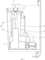
FIG. 1 is a structural schematic view of a water tank and a mounting bracket of a dehumidifier viewed from top to bottom according to an embodiment of the present application. -
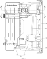
FIG. 2 is a cross-sectional view at W-W inFIG. 1 . -
FIG. 3 is a structural schematic view of a water pump assembly and a middle partition of a dehumidifier according to an embodiment of the present application. -
FIG. 4 is a structural schematic view of a middle partition plate and a water tank assembled together and viewed from top to bottom according to an embodiment of a dehumidifier of the present application. -
FIG. 5 is a structural schematic view of the cross-sectional view at X-X inFIG. 4 after rotating 180° counterclockwise. -
FIG. 6 is an enlarged view of A inFIG. 5 . -
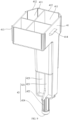
FIG. 7 is a structural schematic view of the mounting bracket and the liquid level detection device inFIG. 5 viewed from top to bottom. -
FIG. 8 is a cross-sectional view of Y-Y inFIG. 7 . -
FIG. 9 is a structural schematic view of the floating part and the trigger part inFIG. 8 from another perspective. -
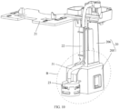
FIG. 10 is a structural schematic view of the mounting bracket and the liquid level detection device inFIG. 7 from another perspective. -
FIG. 11 is an enlarged view of B inFIG. 10 . -
FIG. 12 is a cross-sectional view at Z-Z inFIG. 4 . -
FIG. 13 is an enlarged view of C inFIG. 12 . -
FIG. 14 is an enlarged view of D inFIG. 3 . -
FIG. 15 is an exploded view of the fixed bracket and the second joint inFIG. 3 . -
FIG. 16 is an exploded view of the drainage joint and the drainage pipe inFIG. 3 . -
number name number name 10 water tank 341 snap 20 mounting bracket 40 liquid level detection device 201 accommodation cavity 41 floating part 202 water inlet 411 floating cavity 203 limit hole 412 opening 204 positioning hole 413 sliding convex rib 205 first mounting section 414 limit protrusion 206 second mounting section 42 trigger part 21 water tank cover 421 connecting rod part 22 fixed structure 422 positioning column 221 connection part 423 connection plate 222 shielding part 424 trigger piece 223 transition section 43 detection switch 224 limiting convex rib 51 water pumping pipe 23 filter bracket 52 water pump 231 water filter joint 53 first joint 24 filter cover 54 second joint 241 filter water inlet 541 sealing groove 30 middle partition plate 55 drainage joint 31 support plate 56 drainage pipe 32 water receiving tray 561 marking part 33 mounting plate 60 sealing member 331 mounting through hole 70 anti-falling piece 332 fixed bayonet 57 first connection pipe 34 fixed bracket 58 second connection pipe - The realization of the purpose, functional features and advantages of the present application will be further described in conjunction with the embodiments and with reference to the accompanying drawings.
- The technical solutions in the embodiments according to the present application will be clearly and completely described below in conjunction with the accompanying drawings in the embodiments according to the present application, and it is clear that the described embodiments are only a part of the embodiments according to the present application, and not all of the embodiments. Based on the embodiments in the present application, all other embodiments obtained by those of ordinary skill in the art without making creative labor fall within the scope of the present application.
- It should be noted that, if there are directional instructions (such as up, down, left, right, front, back or the like) involved in the embodiments of the present application, the directional indications are only used to explain the relative positional relationship, movement and so on between various components in a specific posture (as shown in the accompanying drawings). If the specific posture changes, the directional indication will also change accordingly.
- In addition, if there are descriptions involving "first", "second" or the like in the present application, the descriptions of "first", "second" or the like are only for descriptive purposes and cannot be understood as indicating or implying the relative importance or implicitly indicating the quantity of the technical features indicated. Therefore, features defined as "first" and "second" may explicitly or implicitly include at least one of these features. In addition, the meaning of "and/or" appearing in the entire text includes three parallel solutions, taking "A and/or B" as an example, it includes solution A, or solution B, or a solution that satisfies both A and B at the same time. In addition, the technical solutions of various embodiments can be combined with each other, but it must be based on that those of ordinary skill in the art can realize. When the combination of technical solutions is contradictory or cannot be realized, it should be considered that such combination of technical solutions does not exist and is not within the protection scope claimed by the present application.
- The present application proposes a dehumidifier.
- In an embodiment according to the present application, please referring to
FIG. 1 to FIG. 3 , the dehumidifier includes amiddle partition plate 30, awater tank 10, a mountingbracket 20, a liquidlevel detection device 40 and a water pump assembly. Thewater tank 10 is provided at one side of themiddle partition plate 30. An outer surface of the mountingbracket 20 is provided with a fixedstructure 22. The liquidlevel detection device 40 is provided at the mountingbracket 20. The water pump assembly includes awater pumping pipe 51 provided at the fixedstructure 22, and a water inlet end of thewater pumping pipe 51 is provided at a bottom of thewater tank 10. - In the embodiment, the mounting
bracket 20 is provided in thewater tank 10, and the water pump assembly is configured to discharge the water in thewater tank 10 to the outside of the dehumidifier. Specifically, the water pump assembly further includes awater pump 52 and adrainage pipe 56, the water inlet end of thewater pump 52 communicates with thewater pumping pipe 51, the water outlet end of thewater pump 52 communicates with thedrainage pipe 56, and thedrainage pipe 56 is configured to discharge water to the outside of the dehumidifier. The dehumidifier further includes a controller, the liquidlevel detection device 40 and the water pump assembly are both electrically connected to the controller, so that when the liquidlevel detection device 40 detects that the water in thewater tank 10 reaches the preset water level, the water level signal can be transmitted to the controller, and then the controller controls the water pump assembly to pump water to discharge the water in thewater tank 10. Certainly, in other embodiments, the liquidlevel detection device 40 can also be electrically connected to an alarm to remind the user by the alarm, and the user manually starts the water pump assembly to pump water. - The preset water level can be located at the high water level of the
water tank 10, that is, the preset water level is located at the upper end of thewater tank 10. When the water in thewater tank 10 reaches the preset water level, it means that thewater tank 10 is about to be full of water, at this time, the water in the water tank10 can be discharged by starting the water pump assembly. The preset water level can be located at the low water level of thewater tank 10, that is, the preset water level is located at the bottom of thewater tank 10. When the water in thewater tank 10 reaches the preset water level, the water in thewater tank 10 at least covers thewater inlet 202 of thewater pumping pipe 51, at this time, the water in thewater tank 10 can be discharged by starting the water pump assembly, thus avoiding the situation where the water pump assembly is started when there is no water or too much water in thewater tank 10. - The technical solution according to the present application is to provide a mounting
bracket 20, a liquidlevel detection device 40 and a water pump assembly on the dehumidifier, and install the liquidlevel detection device 40 and thewater pumping pipe 51 of the water pump assembly at the mountingbracket 20, thus making the water inlet end of thewater pumping pipe 51 be provided at the bottom of thewater tank 10. In this way, the water level in thewater tank 10 can be detected by the liquidlevel detection device 40, and then the water pump assembly can be started or shut down according to the water level in thewater tank 10, thus using the water pump assembly to automatically drain the water in thewater tank 10, which greatly facilitates the drainage of thewater tank 10, avoids the need for users to pour water more frequently during the dehumidification process, and reduces the number of times the user pours water. Compared with the method where thewater pumping pipe 51 and the liquidlevel detection device 40 each have an mounting rack, in this solution, the liquidlevel detection device 40 and thewater pumping pipe 51 of the water pump assembly are both provided at the mountingbracket 20, which can reduce the number of parts of the dehumidifier and improve the compact structure of the dehumidifier. Moreover, the liquidlevel detection device 40 can be configured to determine that there is water in thewater tank 10 before starting the water pump assembly, which can prevent the water pump assembly from being started when there is no water or too much water in thewater tank 10, which is beneficial to extending the life of the water pump assembly. - Please referring to
FIG. 4 to FIG. 9 , in an embodiment, the mountingbracket 20 is provided with anaccommodation cavity 201 and awater inlet 202 communicating with theaccommodation cavity 201, thewater inlet 202 is provided at a bottom of the mountingbracket 20, the liquidlevel detection device 40 includes a floatingpart 41, atrigger part 42 and adetection switch 43, the floatingpart 41 is movably provided at theaccommodation cavity 201, thetrigger part 42 is connected to the floatingpart 41, thedetection switch 43 is provided at intervals above thetrigger part 42, and thetrigger part 42 triggers the detection switch when the floatingpart 41 floats upward under the action of water. Specifically, thewater inlet 202 is provided at the bottom surface of the mountingbracket 20. In an embodiment, thewater inlet 202 is provided as anopening 412 to simplify the structure of the mountingbracket 20. Under the action of gravity, the floatingpart 41 can at least move down to thewater inlet 202 to ensure that water can contact the floatingpart 41 when water enters from thewater inlet 202. Thedetection switch 43 can be provided on the mountingbracket 20 or on themiddle partition plate 30 of the dehumidifier, as long as thedetection switch 43 is provided at intervals above thetrigger part 42, and thetrigger part 42 can trigger the detection switch when the floatingpart 41 floats upward under the action of water. Certainly, thewater inlet 202 can also be provided at the side of the mountingbracket 20 and near the bottom. - When the liquid
level detection device 40 is used on the dehumidifier, the mountingbracket 20 can be placed at the bottom of thewater tank 10, so that the floatingpart 41 is located at the bottom of thewater tank 10. In this way, after the dehumidifier starts working, when the water in thewater tank 10 gradually increases until the buoyancy force produced by the water on the floatingpart 41 is greater than the gravity of the floatingpart 41 and the gravity of thetrigger part 42, the floatingpart 41 can drive thetrigger part 42 to move upward, so that thedetection switch 43 can be triggered by thetrigger part 42. At this time, it can be determined that there is water in thewater tank 10, when the dehumidifier is provided with a water pump assembly for draining thewater tank 10, the waterpump water pump 52 can be started to drain the water, thus avoiding the situation where thewater pump 52 is started when there is no water in thewater tank 10. In addition, the mountingbracket 20 can also be placed near the top of thewater tank 10, so that the floatingpart 41 is located near the top of thewater tank 10, when the water in thewater tank 10 is almost full, thedetection switch 43 can be triggered by thetrigger part 42 to generate an alarm. - In an embodiment, the floating
part 41 is integrally formed with thetrigger part 42, thus reducing the assembly process of the floatingpart 41 and thetrigger part 42, which is beneficial to improving assembly efficiency and can ensure reliable connection between the floatingpart 41 and thetrigger part 42. Certainly, in other embodiments, the floatingpart 41 and thetrigger part 42 are detachably connected. - In an embodiment, the floating
part 41 is provided with a floatingcavity 411 and anopening 412 communicating with the floatingcavity 411, and theopening 412 is provided at a bottom of the floatingpart 41. Specifically, theopening 412 is provided at the bottom surface of the floatingpart 41, that is, theopening 412 is placed downward. After the liquidlevel detection device 40 is installed at thewater tank 10 of the dehumidifier, when the water in thewater tank 10 reaches theopening 412, the water can seal off theopening 412, causing the floatingcavity 411 to form a complete sealed cavity, at this time, the floatingcavity 411 is filled with gas, and the floatingpart 41 floats when the water surface rises to a point where the buoyancy force is greater than gravity. In this way, when theopening 412 is provided at the bottom of the floatingpart 41, the floatingcavity 411 can be easily formed. Moreover, there is no need to provide an additional cover plate at theopening 412, thus, it can reduce the number of parts and the assembly process of the floatingpart 41, and also reduce the overall weight of the floatingpart 41, which is beneficial to improving the floating speed of floating part41. Certainly, in other embodiments, the floatingcavity 411 may also be a sealed cavity; or the floatingpart 41 may be made of foam material. - In an embodiment, the floating
part 41 is provided with a plurality of floatingcavities 411, and the floatingpart 41 is provided with anopening 412 corresponding to each floatingcavity 411. Specifically, at least two floatingcavities 411 are provided, two adjacent floatingcavities 411 are separated by partition plate, and theopenings 412 of each floatingcavity 411 are provided at the same horizontal plane. By providing the plurality of floatingcavities 411, the buoyancy of the floatingpart 41 can be increased. Moreover, compared with the case of providing one large cavity, separating multiple floating cavities can make the structural strength of the floatingpart 41 higher, thus reducing the possibility of deformation of the floating part, and ensuring the structural reliability of the floatingpart 41. Certainly, in other embodiments, the floatingpart 41 may also be provided with only one floatingcavity 411. - In an embodiment, one of the floating
part 41 and a cavity wall of theaccommodation cavity 201 is provided with a slidingconvex rib 413 slidingly abutted against the other of the floatingpart 41 and the cavity wall of theaccommodation cavity 201, and the slidingconvex rib 413 is configured to extend along an up and down direction. Specifically, a slidingconvex rib 413 may be provided at the cavity wall of theaccommodation cavity 201, and the slidingconvex rib 413 is in sliding contact with the outer side surface of the floatingpart 41. A slidingconvex rib 413 may also be provided at the outer side surface of the floatingpart 41, and the slidingconvex rib 413 is in sliding contact with the cavity wall of theaccommodation cavity 201. In this way, the contact area between the cavity wall of theaccommodation cavity 201 and the floatingpart 41 can be reduced, that is, the friction between the cavity wall of theaccommodation cavity 201 and the floatingpart 41 can be reduced, and the resistance of the floatingpart 41 when it moves upward in theaccommodation cavity 201 can be reduced, thus making it easier for the floatingpart 41 to move upward in theaccommodation cavity 201, thereby increasing the floating speed of the floatingpart 41. Certainly, in other embodiments, the slidingconvex rib 413 may not be provided. - In an embodiment, a plurality of sliding
convex ribs 413 are provided, and the plurality of slidingconvex ribs 413 are provided at intervals in the circumferential direction of the floatingpart 41. Specifically, slidingconvex ribs 413 are provided around the floatingpart 41, so that all positions in the circumferential direction of the floatingpart 41 can be slidingly contacted by slidingconvex ribs 413, thus avoiding the situation where the outer side surface of the floatingpart 41 is in contact with the cavity wall surface of theaccommodation cavity 201. - In an embodiment, the mounting
bracket 20 is further provided with apositioning hole 204 communicating with theaccommodation cavity 201, thetrigger part 42 includes a connectingrod part 421 and atrigger piece 424, the connectingrod part 421 is connected to the floatingpart 41, thetrigger piece 424 is provided at an upper end of the connectingrod part 421, and the connectingrod part 421 is slidingly provided in thepositioning hole 204. Specifically, thetrigger piece 424 is configured to trigger thedetection switch 43, thepositioning hole 204 extends along the up and down direction, and the connectingrod part 421 can slide in thepositioning hole 204 along the up and down direction. With this arrangement, thepositioning hole 204 can be configured for positioning and installation of the connectingrod part 421, and thepositioning hole 204 can also be configured to limit the deflection of the connectingrod part 421 during the up and down movement, thus ensuring the movement stability of the connectingrod part 421. Certainly, in other embodiments, the mountingbracket 20 may also be provided with a guide column extending along the up and down direction, and the connectingrod part 421 is provided with a guide hole for slidingly matching the guide column. - In an embodiment, the
trigger piece 424 is a magnet, and thedetection switch 43 is a magnetic switch; or, thetrigger piece 424 is a light blocking piece or a reflective piece, and thedetection switch 43 is a laser sensor; or, thetrigger piece 424 is a trigger head, and thedetection switch 43 is a tact switch. Specifically, when thetrigger piece 424 is a trigger head and thedetection switch 43 is a tact switch, thetrigger piece 424 can trigger thedetection switch 43 by directly touching thedetection switch 43. When thetrigger piece 424 is a magnet and thedetection switch 43 is a magnetic switch, thedetection switch 43 can be triggered only when thetrigger piece 424 moves up to the preset position with the floatingpart 41, in this way, thetrigger piece 424 does not need to be in contact with thedetection switch 43, so thedetection switch 43 can be provided to be sealed and the risk of water intrusion in thedetection switch 43 is reduced. When thetrigger piece 424 is a light blocking piece or a reflective piece and thedetection switch 43 is a laser sensor, similarly, thedetection switch 43 can be triggered only when thetrigger piece 424 moves up to the preset position with the floatingpart 41, in this way, thetrigger piece 424 does not need to be in contact with thedetection switch 43, so thedetection switch 43 can be provided to be sealed and the risk of water intrusion in thedetection switch 43 is reduced. - In an embodiment, the connecting
rod part 421 includes apositioning column 422 and a plurality ofconnection plates 423, eachconnection plate 423 is provided with a connecting side edge extending along the up and down direction, the connecting side edge of eachconnection plate 423 is connected to each other, eachconnection plate 423 is connected to the floatingpart 41, thepositioning column 422 is connected to the connection point at the upper end of eachconnection plate 423, and thepositioning column 422 is slidingly provided in thepositioning hole 204. Specifically, at least twoconnection plates 423 are provided, twoadjacent connection plates 423 are provided at an included angle, that is, the positions between twoadjacent connection plates 423 are provided in a gap. Compared with the connectingrod part 421 having a solid columnar structure, in this way, the weight of the connectingrod part 421 can be reduced under the condition of ensuring that the connectingrod part 421 has sufficient structural strength, thus making it easier for the floatingpart 41 to move upward and increasing the floating speed of the floatingpart 41. In an embodiment, the floatingpart 41 is integrally formed with the connectingrod part 421. - Please referring to
FIG. 8 to FIG. 11 , in an embodiment, a cavity wall of theaccommodation cavity 201 is provided with alimit hole 203, the side of the floatingpart 41 is provided with alimit protrusion 414, thelimit protrusion 414 extends into thelimit hole 203 to limit the movement of the floatingpart 41 toward the outside of theaccommodation cavity 201. Specifically, the size of thelimit protrusion 414 is smaller than the size of thelimit hole 203. When the floatingpart 41 is in a waterless environment, under the action of gravity, thelimit protrusion 414 abuts against the lower edge of thelimit hole 203, and the upper edge of thelimit protrusion 414 and the upper edge of thelimit hole 203 are provided at intervals. When the floatingpart 41 floats upward under the action of water, thelimit protrusion 414 can move upward in thelimit hole 203. By providing alimit protrusion 414 at the side of the floatingpart 41, when thelimit protrusion 414 extends into thelimit hole 203 in the cavity wall of theaccommodation cavity 201, the floatingpart 41 can be prevented from detaching from theaccommodation cavity 201, and the floatingpart 41, thetrigger part 42 and the mountingbracket 20 can be assembled into an integral component, making it easy to install in the water tank of the dehumidifier. Certainly, in other embodiments, a limiting flange may also be provided at thewater inlet 202 to limit the movement of the floatingpart 41 toward the outside of theaccommodation cavity 201. - Please referring to
FIG. 10 andFIG. 11 , in an embodiment, the fixedstructure 22 includes aconnection part 221 and a shieldingpart 222, theconnection part 221 is connected to the outer surface of the mountingbracket 20, the shieldingpart 222 is connected to theconnection part 221 and is spaced apart from the outer surface of the mountingbracket 20, and thewater pumping pipe 51 is clamped between the shieldingpart 222 and the outer surface of the mountingbracket 20. Specifically, the fixedstructure 22 further includes a limitingconvex rib 224, the limitingconvex rib 224 is provided at the side of the shieldingpart 222 facing the outer surface of the mountingbracket 20, the limitingconvex rib 224 and theconnection part 221 are provided at intervals, thewater pumping pipe 51 is provided between the limitingconvex rib 224 and theconnection part 221, that is, the limitingconvex rib 224 can limit the movement of thewater pumping pipe 51 away from theconnection part 221, thus ensuring that thewater pumping pipe 51 is stably fixed on the mountingbracket 20. The fixedstructure 22 is integrally formed on the mountingbracket 20, that is, theconnection part 221, the shieldingpart 222 and the limitingconvex rib 224 are integrally formed. Compared with the method of fixing thewater pumping pipe 51 to the mountingbracket 20 by clamps or screws, in this way, it can reduce the number of parts, thereby reducing the assembly process and improving assembly efficiency. Certainly, in other embodiments, the distance between the shieldingpart 222 and the outer surface of the mountingbracket 20 can also be made smaller than the outer diameter of thewater pumping pipe 51, so that thewater pumping pipe 51 is clamped between the shieldingpart 222 and the outer surface of the mountingbracket 20. - In an embodiment, the mounting
bracket 20 includes afirst mounting section 205 and asecond mounting section 206 connected to an upper end of thefirst mounting section 205, thewater inlet 202 is provided at the bottom of thefirst mounting section 205, the interiors of thefirst mounting section 205 and thesecond mounting section 206 form anaccommodation cavity 201 together, the floatingpart 41 is provided in thefirst mounting section 205, the trigger part 42 (connecting rod part 421) is provided in thesecond mounting section 206, and the circumferential size of thesecond mounting section 206 is smaller than the circumferential size of the first mounting section. In order to ensure that the floatingpart 41 has greater buoyancy and reduce the weight of the trigger part 42 (connecting rod part 421) at the same time, the floatingpart 41 can be provided larger, while the size of the trigger part 42 (connecting rod part 421) is provided smaller. By making the circumferential size of thesecond mounting section 206 smaller than the circumferential size of the first mounting section, the gap between thesecond mounting section 206 and the trigger part 42 (connecting rod part 421) can be smaller, which is beneficial to reducing the overall size of the mountingbracket 20 and improving the structural compactness of the dehumidification device. Moreover, when the mountingbracket 20 is provided in thewater tank 10, the space occupied by the mountingbracket 20 in thewater tank 10 can be reduced, so that thewater tank 10 can accommodate more water. - In an embodiment, the shielding
part 222 is provided at thesecond mounting section 206 and extends along the up and down direction, the lower end of the shieldingpart 222 is provided with atransition section 223, thetransition section 223 is located at the connection between thefirst mounting section 205 and thesecond mounting section 206, and thewater pumping pipe 51 is located between thetransition section 223 and the surface of the mountingbracket 20. In this way, the part of thewater pumping pipe 51 located at the connection between thefirst mounting section 205 and thesecond mounting section 206 can be constrained by thetransition section 223, which allows thewater pumping pipe 51 to fit better on the surface of the mountingbracket 20, thus making the assembled component structure of the mountingbracket 20 and thewater pumping pipe 51 more compact. In an embodiment, thetransition section 223 is in a convex arc shape protruding toward the connection between thefirst mounting section 205 and thesecond mounting section 206, which is beneficial to the smooth transition of the part of thewater pumping pipe 51 located at the connection between thefirst mounting section 205 and thesecond mounting section 206. - In an embodiment, the dehumidifier further includes a
filter bracket 23, thefilter bracket 23 is provided with a filter cavity and a water filter joint 231 communicating with the filter cavity, and a lower end of thewater pumping pipe 51 is connected to thewater filter joint 231. In this embodiment, thefilter bracket 23 is connected to the bottom of the mountingbracket 20. Thefilter bracket 23 is provided with a downward-facing mounting opening. The dehumidifier further includes a filter screen and afilter cover 24. The filter screen is provided in the filter cavity, and thefilter cover 24 covers the mounting opening to limit the filter screen in the filter cavity, thefilter cover 24 is provided with afilter water inlet 241 communicating with the filter cavity. In this way, impurities such as dust particles in the water in thewater tank 10 can be filtered, thus reducing the situation where impurities enter the water pump assembly and cause blockage of the water pump assembly. Moreover, by connecting thefilter bracket 23 to the mountingbracket 20, thefilter bracket 23 can be firmly fixed, thus avoiding the situation wherefilter bracket 23 andwater pumping pipe 51 shake. Certainly, in other embodiments, the filter screen can also be stuck on the cavity wall of the filter cavity, so that thefilter cover 24 does not need to be provided. In addition, in other embodiments, thefilter bracket 23 and the mountingbracket 20 are provided separately. - In an embodiment, the fixed
structure 22 is integrally formed with the mountingbracket 20. Specifically, theconnection part 221, the shieldingpart 222, the limitingconvex rib 224, thetransition section 223 and the filterbracket filter bracket 23 are integrally formed on the mountingbracket 20, which facilitates molding, thus reducing the assembly process of the fixedstructure 22 and the mountingbracket 20, improving assembly efficiency, and also ensuring reliable connection between the fixedstructure 22 and the mountingbracket 20. Certainly, in other embodiments, the fixedstructure 22 can also be clamped or connected to the mountingbracket 20 by screws. - Please referring to
FIG. 1 ,FIG. 2 ,FIG. 3 ,FIG. 12 andFIG. 13 , in an embodiment, the water pump assembly further includes a first joint 53 and a second joint 54, the second joint 54 is provided at themiddle partition plate 30, the first joint 53 is provided at the mountingbracket 20, one end of the first joint 53 is connected to thewater pumping pipe 51, and another end of the first joint 53 is inserted into the first joint 54. When the first joint 53 is inserted into the second joint 54, the first joint 53 and the second joint 54 can be communicated with, that is, the water flowing from thewater pumping pipe 51 to the first joint 53 can flow to the second joint 54 and be discharged from the second joint 54. By inserting and mating the first joint 53 with the second joint 54, the connection between the first joint 53 and the second joint 54 can be facilitated during the process of disassembly and assembly thewater tank 10. Moreover, by directly providing the second joint 54 on themiddle partition plate 30, there is no need to provide an additional mounting base, thus eliminating the need for a mounting base, reducing the cost of the dehumidifier and improving the assembly efficiency of the dehumidifier. The first joint 53 can be inserted into the second joint 54, or the second joint 54 can also be inserted into the first joint 53. - In an embodiment, the dehumidifier further includes a housing, the
middle partition plate 30 is provided in the housing, the housing is provided with a water tank assembly port for disassembling and assembling thewater tank 10, and the second joint 54 is provided toward the water tank assembly port. That is, one end of the second joint 54 inserted into the first joint 53 faces toward the water tank assembly port, so that the direction in which thewater tank 10 is pushed into the housing is consistent with the insertion direction of the first joint 53 and the second joint 54, therefore, in the process of pushing thewater tank 10 from the water tank assembly port, the first joint 53 and the second joint 54 can be gradually connected, and when thewater tank 10 is installed in place, the first joint 53 and the second joint 54 are also inserted into place. In this way, there is no need to additionally manually connect the first joint 53 and the second joint 54, which facilitates the disassembly and assembly of thewater tank 10. Certainly, in other embodiments, the second joint 54 can also extend downward, and the first joint 53 can extend upward, and thewater tank 10 can move upward after being pushed into the housing, so that the first joint 53 and the second joint 54 are inserted into each other. - Please referring to
FIG. 12 andFIG. 13 , in an embodiment, a sealingmember 60 is provided between the first joint 53 and the second joint 54. In this way, the gap between the first joint 53 and the second joint 54 can be sealed by the sealingmember 60, thereby reducing the risk of water leakage between the first joint 53 and the second joint 54. The sealingmember 60 may be but is not limited to a sealing ring. - In an embodiment, the second joint 54 is sleeved on an outside of the first joint 53, a sealing
groove 541 is provided at an inside of the second joint 54 or an outside of the first joint 53, the sealingmember 60 is limited to the sealinggroove 541, and the sealingmember 60 partially protrudes outside the sealinggroove 541. That is, the first joint 53 is inserted into the second joint 54, in this embodiment, a sealinggroove 541 is provided inside the second joint 54, the sealinggroove 541 is annular and is provided around the outer periphery of the first joint 53. The sealingmember 60 is a sealing ring. When the sealingmember 60 is installed into the sealinggroove 541, the sealingmember 60 partially protrudes from the inner side surface of the second joint 54. When the first joint 53 is inserted into the second joint 54, the sealingmember 60 can be sleeved on the outer periphery of the first joint 53 to seal the gap between the first joint 53 and the second joint 54. In this way, the sealingmember 60 can be limited by the sealinggroove 541, thereby reducing the risk of the sealingmember 60 falling during the insertion and extraction process of the first joint 53 and the second joint 54. - In an embodiment, an
anti-falling piece 70 is provided at an inner side of the second joint 54, and theanti-falling piece 70 is provided between the sealingmember 60 and the sealinggroove 541, which can prevent the sealingmember 60 from coming out of the second joint 54, and further reduce the risk of the sealingmember 60 falling during the insertion and extraction process of the first joint 53 and the second joint 54. - In another embodiment, the first joint 53 is sleeved on an outside of the second joint 54, a sealing
groove 541 is provided at an inside of the first joint 53 or an outside of the second joint 54, the sealingmember 60 is limited to the sealinggroove 541, and the sealingmember 60 partially protrudes outside the sealinggroove 541. In this way, the sealingmember 60 can be limited by the sealinggroove 541, thereby reducing the risk of the sealingmember 60 falling during the insertion and extraction process of the first joint 53 and the second joint 54. - Please referring to
FIG. 3 ,FIG. 12 ,FIG. 13 and FIG. 14 , in an embodiment, themiddle partition plate 30 includes asupport plate 31 and a mountingplate 33 connected to an upper end of thesupport plate 31, thewater tank 10 is provided at one side of thesupport plate 31, the mountingplate 33 is provided above thewater tank 10, the mountingplate 33 is provided with a mounting throughhole 331, and the second joint 54 is provided at the mounting throughhole 331. Specifically, the water pump assembly further includes afirst connection pipe 57, thefirst connection pipe 57 passes through the mounting throughhole 331 and is connected to the second joint 54, that is, one end of the second joint 54 is inserted into the first joint 53, and another end of the second joint 54 is connected to thefirst connection pipe 57. In this way, when the mounting throughhole 331 is provided on the mountingplate 33, thefirst connection pipe 57 of the water pump assembly for connecting the second joint 54 can be passed through, thus avoiding the situation where thefirst connection pipe 57 is passed around the edge of the mountingplate 33 and then connected to the second joint 54, reducing the length of thefirst connection pipe 57, therefore, the space occupied by thefirst connection pipe 57 in the dehumidifier can be reduced, making the internal structure of the dehumidifier more compact. Certainly, in other embodiments, the second joint 54 can also be installed at thesupport plate 31. - Please referring to
FIG. 3 ,FIG. 12 to FIG. 15 , in an embodiment, themiddle partition plate 30 further includes a fixedbracket 34, the fixedbracket 34 is provided at the mounting throughhole 331, and the second joint 54 is provided at the fixedbracket 34. That is, the second joint 54 can be provided at the fixedbracket 34 firstly, and then the fixedbracket 34 can be provided at the mounting throughhole 331. In this way, when the second joint 54 is firstly provided at the fixedbracket 34, the reliability of the connection between the second joint 54 and the fixedbracket 34 can be better ensured, moreover, the connection area between the fixedbracket 34 and the mountingplate 33 can be larger, and more connection positions are provided, which can better ensure the reliability of the connection between the fixedbracket 34 and the mountingplate 33, that is, the assembly stability of the second joint 54 is improved, thereby reducing the risk of the second joint 54 loosening or even falling during the insertion and extraction process of the first joint 53 and the second joint 54. Moreover, during the insertion and extraction process of the first joint53 and the second joint54, the force on the fixedbracket 34 and the mountingplate 33 is distributed widely and evenly, thus reducing the risk of rupture of the mountingplate 33 due to concentrated stress on the fixedbracket 34 and the mountingplate 33. Certainly, in other embodiments, the second joint 54 can also be directly fixed on the mountingplate 33. - In an embodiment, the fixed
bracket 34 is provided with asnap 341 extending upward, thesnap 341 is snapped at the edge of the mounting throughhole 331, which eliminates the need for screw fixation, thus facilitating disassembly and assembly, and helping improve assembly efficiency. Certainly, in other embodiments, the fixedbracket 34 can also be fixed to the mountingplate 33 by screws. - Please referring to
FIG. 3 ,FIG. 12 andFIG. 13 , in an embodiment, the water pump assembly further includes awater pump 52, thewater pump 52 is provided at the mountingplate 33, and a water inlet end of thewater pump 52 is configured to communicate with the second joint 54. Specifically, thewater pump 52 is provided at the upper surface of the mountingplate 33, the water inlet end of thewater pump 52 is connected to thefirst connection pipe 57, that is, one end of thefirst connection pipe 57 is connected to the second joint 54, and another end of thefirst connection pipe 57 is connected to the water inlet end of thewater pump 52. In this way, using the mountingplate 33 to install thewater pump 52 can improve the space utilization on the mountingplate 33 and further improve the structural compactness of the dehumidifier. Moreover, when thewater pump 52 is installed on the mountingplate 33, the length of thefirst connection pipe 57 can be reduced. Certainly, in other embodiments, thewater pump 52 can also be provided at thesupport plate 31 or at the chassis of the dehumidifier. - In an embodiment, a fixed
bayonet 332 is provided at the upper surface of the mountingplate 33, and the fixedbayonet 332 is provided adjacent to the edge of the mounting throughhole 331, thefirst connection pipe 57 is clamped to the fixedbayonet 332. In this way, thefirst connection pipe 57 can better fit on the upper surface of the mountingplate 33, which is beneficial to improving the structural compactness of the upper side of the mountingplate 33. - Please referring to
FIG. 3 andFIG. 16 , in an embodiment, the water pump assembly further includes adrainage joint 55 and adrainage pipe 56, one end of thedrainage joint 55 communicates with thewater pumping pipe 51, another end of thedrainage joint 55 is for thedrainage pipe 56 to be inserted into, one end of thedrainage pipe 56 inserted into thedrainage joint 55 is provided with a markingpart 561, and the markingpart 561 is configured to mark an insertion depth of thedrainage pipe 56 and thedrainage joint 55. Specifically, the water pump assembly further includes asecond connection pipe 58, one end of thesecond connection pipe 58 is connected to the water outlet end of thewater pump 52, and another end of thesecond connection pipe 58 is connected to thedrainage joint 55, so that thedrainage joint 55 communicates with thewater pumping pipe 51. The markingpart 561 is provided at the outer peripheral surface of thedrainage pipe 56, and the markingpart 561 is at least partially spaced from the end of the drainage pipe 56 (the end of thedrainage pipe 56 inserted into the drainage joint 55). When one end of thedrainage pipe 56 provided at the markingpart 561 is inserted into thedrainage joint 55, the insertion depth of thedrainage pipe 56 can be determined by observing the positional relationship between the markingpart 561 and the edge of the socket of thedrainage joint 55. In this way, it can make it easier for the operator to determine the insertion depth of thedrainage pipe 56 and the insert-in joint, that is, it can make it easier for the operator to determine whether thedrainage pipe 56 is installed in place, thus reducing the risk that thedrainage pipe 56 will fall off from the insert-in joint during the drainage process due to excessive insertion depth. The markingpart 561 may be a scale, a groove, a protrusion or a label, etc. - Please referring to
FIG. 7 andFIG. 10 , in an embodiment, the dehumidifier further includes awater tank cover 21, thewater tank cover 21 is connected to an upper end of the mountingbracket 20, and thewater tank cover 21 is configured to cover an opening of thewater tank 10. In this way, thewater tank cover 21 and the mountingbracket 20 are connected together. During installation, thewater tank cover 21 and the mountingbracket 20 can be installed at the same time, which can improve the efficiency of the final assembly. In an embodiment, thewater tank cover 21 and the mountingbracket 20 are integrally formed, which can reduce the assembly process of thewater tank cover 21 and the mountingbracket 20. - Please referring to
FIG. 3 andFIG. 12 , in an embodiment, themiddle partition plate 30 is provided with awater receiving tray 32, the dehumidifier further includes a heat exchanger assembly, the heat exchanger assembly is provided on thewater receiving tray 32, and thewater receiving tray 32 is configured to receive the condensed water generated by the heat exchanger assembly. In this embodiment, thewater receiving tray 32 is connected to the upper end of thesupport plate 31, and the mountingplate 33 and thewater receiving tray 32 are respectively provided at two opposite sides of thesupport plate 31. The dehumidifier further includes a compressor connected to the heat exchanger assembly, the compressor is provided below thewater receiving tray 32, and thewater tank 10 is provided at the side of thesupport plate 31 away from the compressor. The heat exchanger assembly includes an evaporator and a condenser. The water vapor in the air is firstly condensed into water droplets by the evaporator, and the water vapor in the air is removed, and then the air after removing water vapor is heated and dried by the condenser to return the blown wind to normal temperature. Certainly, in other embodiments, the dehumidification device may also adopt dehumidification methods such as adsorption type. - The above are only some embodiments of the present application, and are not intended to limit the scope of the present application. Under the concept of the present application, any equivalent structure transformation made by using the description and accompanying drawings of the present application, or directly or indirectly applied in other related technical fields, is included within the scope of the present application.
Claims (17)
- A dehumidifier, comprising:a middle partition plate;a water tank provided at one side of the middle partition plate;a mounting bracket, wherein an outer surface of the mounting bracket is provided with a fixed structure;a liquid level detection device provided at the mounting bracket; anda water pump assembly comprising a water pumping pipe provided at the fixed structure, wherein a water inlet end of the water pumping pipe is provided at a bottom of the water tank.
- The dehumidifier according to claim 1, wherein the fixed structure comprises a connection part and a shielding part, the connection part is connected to the outer surface of the mounting bracket, the shielding part is connected to the connection part and is spaced apart from the outer surface of the mounting bracket, and the water pumping pipe is clamped between the shielding part and the outer surface of the mounting bracket.
- The dehumidifier according to claim 1, further comprising:a filter bracket,wherein the filter bracket is provided with a filter cavity and a water filter joint communicating with the filter cavity, and a lower end of the water pumping pipe is connected to the water filter joint.
- The dehumidifier according to any one of claims 1 to 3, wherein the fixed structure is integrally formed with the mounting bracket.
- The dehumidifier according to claim 1, wherein the mounting bracket is provided with an accommodation cavity and a water inlet communicating with the accommodation cavity, the water inlet is provided at a bottom of the mounting bracket, the liquid level detection device comprises a floating part, a trigger part and a detection switch, the floating part is movably provided at the accommodation cavity, the trigger part is connected to the floating part, the detection switch is provided above the trigger part, and the trigger part is configured to trigger the detection switch.
- The dehumidifier according to claim 5, wherein the floating part is provided with a floating cavity and an opening communicating with the floating cavity, and the opening is provided at a bottom of the floating part.
- The dehumidifier according to claim 5, wherein one of the floating part and a cavity wall of the accommodation cavity is provided with a sliding convex rib slidingly abutted against the other of the floating part and the cavity wall of the accommodation cavity, and the sliding convex rib is configured to extend along an up and down direction.
- The dehumidifier according to claim 1, wherein the mounting bracket is further provided with a positioning hole communicating with the accommodation cavity, the trigger part comprises a connecting rod part and a trigger piece, the connecting rod part is connected to the floating part, the trigger piece is provided at an upper end of the connecting rod part, and the connecting rod part is slidingly provided in the positioning hole.
- The dehumidifier according to claim 1, wherein the water pump assembly further comprises a first joint and a second joint, the second joint is provided at the middle partition plate, the first joint is provided at the mounting bracket, one end of the first joint is connected to the water pumping pipe, and another end of the first joint is inserted into the first joint.
- The dehumidifier according to claim 9, further comprising:a housing,wherein the middle partition plate is provided in the housing, the housing is provided with a water tank assembly port for disassembling and assembling the water tank, and the second joint is provided toward the water tank assembly port.
- The dehumidifier according to claim 9, wherein a sealing member is provided between the first j oint and the second joint.
- The dehumidifier according to claim 11, wherein:the second joint is sleeved on an outside of the first joint, a sealing groove is provided at an inside of the second joint or an outside of the first joint, the sealing member is limited to the sealing groove, and the sealing member partially protrudes outside the sealing groove; orthe first joint is sleeved on an outside of the second joint, a sealing groove is provided at an inside of the first joint or an outside of the second joint, the sealing member is limited to the sealing groove, and the sealing member partially protrudes outside the sealing groove.
- The dehumidifier according to claim 9, wherein the middle partition plate comprises a support plate and a mounting plate connected to an upper end of the support plate, the water tank is provided at one side of the support plate, the mounting plate is provided above the water tank, the mounting plate is provided with a mounting through hole, and the second joint is provided at the mounting through hole.
- The dehumidifier according to claim 13, wherein the middle partition plate further comprises a fixed bracket, the fixed bracket is provided at the mounting through hole, and the second joint is provided at the fixed bracket.
- The dehumidifier according to claim 13, wherein the water pump assembly further comprises a water pump, the water pump is provided at the mounting plate, and a water inlet end of the water pump is configured to communicate with the second joint.
- The dehumidifier according to claim 1, wherein the water pump assembly further comprises a drainage joint and a drainage pipe, one end of the drainage joint communicates with the water pumping pipe, another end of the drainage joint is for the drainage pipe to be inserted into, one end of the drainage pipe inserted into the drainage joint is provided with a marking part, and the marking part is configured to mark an insertion depth of the drainage pipe into the drainage joint.
- The dehumidifier according to claim 1, further comprising:a water tank cover,wherein the water tank cover is connected to an upper end of the mounting bracket, and the water tank cover is configured to cover an opening of the water tank.
Applications Claiming Priority (3)
| Application Number | Priority Date | Filing Date | Title |
|---|---|---|---|
| CN202122053125.9U CN215808946U (en) | 2021-08-27 | 2021-08-27 | Dehumidifier |
| CN202111000910.6A CN113587275B (en) | 2021-08-27 | 2021-08-27 | Dehumidifier |
| PCT/CN2021/127612 WO2023024255A1 (en) | 2021-08-27 | 2021-10-29 | Dehumidifier |
Publications (2)
| Publication Number | Publication Date |
|---|---|
| EP4394267A1 true EP4394267A1 (en) | 2024-07-03 |
| EP4394267A4 EP4394267A4 (en) | 2025-01-15 |
Family
ID=85322422
Family Applications (1)
| Application Number | Title | Priority Date | Filing Date |
|---|---|---|---|
| EP21954775.9A Pending EP4394267A4 (en) | 2021-08-27 | 2021-10-29 | Dehumidifier |
Country Status (3)
| Country | Link |
|---|---|
| US (1) | US20250129949A1 (en) |
| EP (1) | EP4394267A4 (en) |
| WO (1) | WO2023024255A1 (en) |
Family Cites Families (14)
| Publication number | Priority date | Publication date | Assignee | Title |
|---|---|---|---|---|
| JP2010046639A (en) * | 2008-08-25 | 2010-03-04 | Daikin Ind Ltd | Dehumidifier |
| CN201956275U (en) * | 2011-03-21 | 2011-08-31 | 广东美的电器股份有限公司 | Water-fullness protecting device for water tank |
| JP2013226484A (en) * | 2012-04-24 | 2013-11-07 | Sharp Corp | Dehumidifier |
| KR101560694B1 (en) * | 2013-12-26 | 2015-10-15 | 동부대우전자 주식회사 | Dehumidifier |
| KR102198138B1 (en) * | 2014-07-25 | 2021-01-05 | 에스케이매직 주식회사 | A dehumidifier in use with floating module of water level indicater |
| CN206989389U (en) * | 2017-07-24 | 2018-02-09 | 佛山市金星徽电器有限公司 | A kind of upper water-adding humidifier |
| CN108050602B (en) * | 2017-11-28 | 2020-08-04 | 广东美的制冷设备有限公司 | Dehumidifier |
| CN208487768U (en) * | 2018-06-05 | 2019-02-12 | 奥克斯空调股份有限公司 | A kind of ceiling machine drainage arrangement and ceiling machine |
| CN209639158U (en) * | 2019-03-22 | 2019-11-15 | 广东美的制冷设备有限公司 | dehumidifier |
| CN210004566U (en) * | 2019-04-03 | 2020-01-31 | 开平威技电器有限公司 | mobile air conditioner, chassis assembly and liquid level detection mechanism for preventing scale thereof |
| CN112082241A (en) * | 2019-06-13 | 2020-12-15 | 深圳市联创电器实业有限公司 | An easy-to-clean humidifier |
| KR102770051B1 (en) * | 2019-12-10 | 2025-02-21 | 삼성전자주식회사 | Humidifier |
| CN213180220U (en) * | 2020-09-21 | 2021-05-11 | 伊莱克斯(杭州)家用电器有限公司 | Dehumidifier and liquid level detection control mechanism |
| CN215637676U (en) * | 2021-08-27 | 2022-01-25 | 广东美的制冷设备有限公司 | Liquid level detection device and dehumidifier |
-
2021
- 2021-10-29 WO PCT/CN2021/127612 patent/WO2023024255A1/en not_active Ceased
- 2021-10-29 US US18/686,856 patent/US20250129949A1/en active Pending
- 2021-10-29 EP EP21954775.9A patent/EP4394267A4/en active Pending
Also Published As
| Publication number | Publication date |
|---|---|
| EP4394267A4 (en) | 2025-01-15 |
| WO2023024255A1 (en) | 2023-03-02 |
| US20250129949A1 (en) | 2025-04-24 |
Similar Documents
| Publication | Publication Date | Title |
|---|---|---|
| KR101949354B1 (en) | apparatus for both humidification and air cleaning | |
| US12146669B2 (en) | Window air conditioner | |
| CN108050602B (en) | Dehumidifier | |
| CN108302630A (en) | Dehumidifier | |
| US12498125B2 (en) | Dehumidifier | |
| EP4394267A1 (en) | Dehumidifier | |
| CN208059087U (en) | Dehumidifier | |
| CN113587275B (en) | Dehumidifier | |
| CN215808946U (en) | Dehumidifier | |
| CN223425369U (en) | Dehumidification equipment | |
| CN202928051U (en) | Embedded type air condition indoor machine and drainage device thereof | |
| CN213955491U (en) | Dehumidifier | |
| US12292364B2 (en) | Enricher, enrichment system, sample manufacturing system, and sample detection system | |
| CN215637676U (en) | Liquid level detection device and dehumidifier | |
| CN116136337B (en) | Drainage joint and dehumidifier | |
| CN112178810A (en) | Dehumidifier | |
| CN220017568U (en) | a dehumidifier | |
| CN217358697U (en) | Liquid level detection device | |
| CN209857488U (en) | Drainage device for refrigeration equipment and refrigeration equipment | |
| CN221980555U (en) | Water dispenser for detecting water leakage of pipeline | |
| CN223316421U (en) | water purification equipment | |
| EP4224075A1 (en) | Dehumidifier | |
| CN206940408U (en) | Cistern assembly and Soda water machine | |
| CN111750598B (en) | Drainage device for refrigeration equipment and refrigeration equipment | |
| CN223388690U (en) | Humidification apparatus |
Legal Events
| Date | Code | Title | Description |
|---|---|---|---|
| STAA | Information on the status of an ep patent application or granted ep patent |
Free format text: STATUS: THE INTERNATIONAL PUBLICATION HAS BEEN MADE |
|
| PUAI | Public reference made under article 153(3) epc to a published international application that has entered the european phase |
Free format text: ORIGINAL CODE: 0009012 |
|
| STAA | Information on the status of an ep patent application or granted ep patent |
Free format text: STATUS: REQUEST FOR EXAMINATION WAS MADE |
|
| 17P | Request for examination filed |
Effective date: 20240229 |
|
| AK | Designated contracting states |
Kind code of ref document: A1 Designated state(s): AL AT BE BG CH CY CZ DE DK EE ES FI FR GB GR HR HU IE IS IT LI LT LU LV MC MK MT NL NO PL PT RO RS SE SI SK SM TR |
|
| DAV | Request for validation of the european patent (deleted) | ||
| DAX | Request for extension of the european patent (deleted) | ||
| A4 | Supplementary search report drawn up and despatched |
Effective date: 20241212 |
|
| RIC1 | Information provided on ipc code assigned before grant |
Ipc: F24F 13/22 20060101ALI20241209BHEP Ipc: F24F 13/00 20060101ALI20241209BHEP Ipc: F24F 11/64 20180101ALI20241209BHEP Ipc: F24F 3/14 20060101AFI20241209BHEP |
|
| STAA | Information on the status of an ep patent application or granted ep patent |
Free format text: STATUS: EXAMINATION IS IN PROGRESS |
|
| 17Q | First examination report despatched |
Effective date: 20260318 |