EP4394253A1 - Gas turbine engine - Google Patents
Gas turbine engine Download PDFInfo
- Publication number
- EP4394253A1 EP4394253A1 EP22217343.7A EP22217343A EP4394253A1 EP 4394253 A1 EP4394253 A1 EP 4394253A1 EP 22217343 A EP22217343 A EP 22217343A EP 4394253 A1 EP4394253 A1 EP 4394253A1
- Authority
- EP
- European Patent Office
- Prior art keywords
- combustor
- stage
- combustion chamber
- turbine engine
- gas turbine
- Prior art date
- Legal status (The legal status is an assumption and is not a legal conclusion. Google has not performed a legal analysis and makes no representation as to the accuracy of the status listed.)
- Granted
Links
Images

Classifications
-
- F—MECHANICAL ENGINEERING; LIGHTING; HEATING; WEAPONS; BLASTING
- F23—COMBUSTION APPARATUS; COMBUSTION PROCESSES
- F23R—GENERATING COMBUSTION PRODUCTS OF HIGH PRESSURE OR HIGH VELOCITY, e.g. GAS-TURBINE COMBUSTION CHAMBERS
- F23R3/00—Continuous combustion chambers using liquid or gaseous fuel
- F23R3/42—Continuous combustion chambers using liquid or gaseous fuel characterised by the arrangement or form of the flame tubes or combustion chambers
-
- F—MECHANICAL ENGINEERING; LIGHTING; HEATING; WEAPONS; BLASTING
- F02—COMBUSTION ENGINES; HOT-GAS OR COMBUSTION-PRODUCT ENGINE PLANTS
- F02C—GAS-TURBINE PLANTS; AIR INTAKES FOR JET-PROPULSION PLANTS; CONTROLLING FUEL SUPPLY IN AIR-BREATHING JET-PROPULSION PLANTS
- F02C3/00—Gas-turbine plants characterised by the use of combustion products as the working fluid
- F02C3/14—Gas-turbine plants characterised by the use of combustion products as the working fluid characterised by the arrangement of the combustion chamber in the plant
-
- F—MECHANICAL ENGINEERING; LIGHTING; HEATING; WEAPONS; BLASTING
- F23—COMBUSTION APPARATUS; COMBUSTION PROCESSES
- F23R—GENERATING COMBUSTION PRODUCTS OF HIGH PRESSURE OR HIGH VELOCITY, e.g. GAS-TURBINE COMBUSTION CHAMBERS
- F23R3/00—Continuous combustion chambers using liquid or gaseous fuel
- F23R3/28—Continuous combustion chambers using liquid or gaseous fuel characterised by the fuel supply
- F23R3/34—Feeding into different combustion zones
- F23R3/346—Feeding into different combustion zones for staged combustion
-
- F—MECHANICAL ENGINEERING; LIGHTING; HEATING; WEAPONS; BLASTING
- F23—COMBUSTION APPARATUS; COMBUSTION PROCESSES
- F23R—GENERATING COMBUSTION PRODUCTS OF HIGH PRESSURE OR HIGH VELOCITY, e.g. GAS-TURBINE COMBUSTION CHAMBERS
- F23R3/00—Continuous combustion chambers using liquid or gaseous fuel
- F23R3/28—Continuous combustion chambers using liquid or gaseous fuel characterised by the fuel supply
- F23R3/36—Supply of different fuels
-
- F—MECHANICAL ENGINEERING; LIGHTING; HEATING; WEAPONS; BLASTING
- F23—COMBUSTION APPARATUS; COMBUSTION PROCESSES
- F23R—GENERATING COMBUSTION PRODUCTS OF HIGH PRESSURE OR HIGH VELOCITY, e.g. GAS-TURBINE COMBUSTION CHAMBERS
- F23R3/00—Continuous combustion chambers using liquid or gaseous fuel
- F23R3/42—Continuous combustion chambers using liquid or gaseous fuel characterised by the arrangement or form of the flame tubes or combustion chambers
- F23R3/50—Combustion chambers comprising an annular flame tube within an annular casing
-
- F—MECHANICAL ENGINEERING; LIGHTING; HEATING; WEAPONS; BLASTING
- F23—COMBUSTION APPARATUS; COMBUSTION PROCESSES
- F23R—GENERATING COMBUSTION PRODUCTS OF HIGH PRESSURE OR HIGH VELOCITY, e.g. GAS-TURBINE COMBUSTION CHAMBERS
- F23R2900/00—Special features of, or arrangements for continuous combustion chambers; Combustion processes therefor
- F23R2900/03341—Sequential combustion chambers or burners
Definitions
- the present invention relates to a gas turbine engine.
- a gas turbine engine comprising:
- the invention allows to exploit the advantages of sequential combustion in gas turbine engines having a single annular combustion chamber.
- the annular combustion chamber serves all the second combustor stages, while the first stage of combustion takes place separately without mixing flows of different combustors.
- Sequential combustion is very flexible and allows to meet requests on performance and pollutant emission with a wide range of fuels, that include hydrogen, ammonia, natural gas and syngas.
- fuels that include hydrogen, ammonia, natural gas and syngas.
- the benefit of sequential combustion may be made available for machines of any size, i.e. for complex and costly high-class gas turbines as well as for lower class and lower size gas turbines, which are less expensive, simpler and more compact and therefore also suitable for a variety of applications.
- the annular combustion chamber defines a common combustion chamber for the second combustor stages of the combustors.
- Microburners allows to produce short flames, with fronts near the respective nozzles. As space occupied by each microburner is very small, many of them may be distributed around the combustor axis to obtain combustion conditions in accordance with design preferences. Turbulence caused by outlets of neighboring microburners favor rapid and effective mixing of fuel and air and allow satisfactory combustion conditions even in small space. Very compact combustors may thus be made.
- each combustor comprises a combustor casing, delimiting the respective gas flow path, and a supporting plate arranged to close an upstream end of the combustor casing and supporting the microburners of the respective combustor, and wherein each microburner comprises a fuel conduit and an air conduit forming first stage nozzles at a nozzle surface of the respective supporting plate adjacent to the gas flow path.
- each nozzle surface has a density of first stage nozzles between 50 nozzles/m 2 and 300 nozzles/m 2 .
- Such a density of first stage nozzles assures effective mixing and reliable flame conditions to avoid pollutant emissions.
- each combustor comprises a central lance injector extending through the respective supporting plate up to the respective second combustor stage.
- the gas turbine engine comprises a compressor and a combustion chamber casing, defining a common air plenum configured to receive compressed air from the compressor and to supply the compressed air to the combustors.
- the combustors are housed in the common air plenum, between the combustion chamber casing and the annular combustion chamber, the combustors being preferably configured to receive air directly from the common air plenum.
- Part of the combustor assembly 3, including one of the combustors 6, is illustrated in greater detail in figure 2 .
- the combustor 6 is also shown in isolation in figures 3 and 4 . It is herein understood that all the burners 6 have the identical structure.
- the combustors 6 are circumferentially distributed around the annular combustion chamber 7 and are in fluid communication with the interior thereof through respective coupling ports 13.
- the combustors 6 are secured to the combustion chamber casing 10 by mounting plates 14 through mounting ports 15 in the combustion chamber casing 10.
- the mounting plates 14 seal the mounting ports 15, so that air is fed to the combustors 6 only from the common plenum 11.
- the combustors 6 are housed in the common air plenum 11, between the combustion chamber casing 10 and the annular combustion chamber 7.
- the mounting plates 14 and the mounting ports 15 allow connection of the combustor 6 to the fuel supply system 8.
- the first combustor stage 6a of each combustor comprises a plurality of respective microburners 23 supported by the supporting plate 21 and distributed around the respective combustor axis C.
- each microburner 23 comprises a fuel conduit 24 and an air conduit 25 coaxially arranged and forming first stage nozzles 27 at a nozzle surface 21a of the respective supporting plate 21 adjacent to the gas flow path 20.
- the number of first stage nozzles 27 is selected such that the nozzle surfaces 21a of the supporting plates 21 have a density of first stage nozzles 27 between 50 nozzles/m 2 and 300 nozzles/m 2 .
- microburners 23 have the respective fuel conduits 24 coupled to the fuel plenum 22 of the respective combustor 6.
- microburners 23 of a group of have the respective fuel conduits 24 coupled to the fuel plenum 22, whereas microburners 23 of another group are decoupled from the fuel plenum 22, thus simply defining air passages.
- the fuel plenum 22 is in turn coupled to the first fuel line 8a of the fuel supply system 8 through a first stage valve 26.
- the air conduits 25 are spaced apart from the fuel plenum 22, so that air may be fed to the microburners 23 through passages between the fuel plenum 22.
- the microburners 23 are configured to create flames at a short distance from the nozzle surfaces 21a and turbulence created by air and fuel flows leaving the first stage nozzles 27 favors mixing.
- the microburners 23 may be designed so that first stage flames are confined substantially to the cylindrical portion 18a of the combustor casing 18, where a reaction zone is defined.
- Each combustor 6 also comprises a central lance injector 28, extending through the respective supporting plate 21 and fuel plenum 22 into the combustor casing 18, up to the respective second combustor stage 6b, in the end divergent portion 18c of the combustor casing 18.
- Each central lance injector 28 comprises an inner fuel conduit 30 coupled to the second fuel line 8b of the fuel supply system 8 through respective second stage valves 31.
- the central lance injector 28 has air inlets 32 circumferentially arranged upstream of the supporting plate 21 and second stage nozzles 33 supplied by the inner fuel conduit 30 and configured to deliver fuel into the gas flow path 20 at the second stage combustor.
- the second stage nozzles 33 may be configured to deliver fuel into the gas flow path 20 substantially in a radial, crossflow direction.
- a gas turbine engine 100 comprises the compressor 2, a combustor assembly 103 and the expansion section or turbine 5.
- the combustor assembly 103 comprises the common annular combustion chamber 7 and a plurality of two-stage sequential combustors 106 circumferentially distributed around the annular combustion chamber 7 and communicating with the annular combustion chamber 7 through the coupling ports 13.
- Each sequential combustors 106 comprises a first combustor stage 106a, a second combustor stage 106b, a transition duct 107 and a dilution air mixer 135.
- the first combustor stage 106a, the transition duct 107 and the dilution air mixer 135 are housed in a combustor casing 118 outside the combustion chamber casing 10, whereas the second combustor stage 106b is accommodated in the common plenum 11.
- the combustor casing 118 has a first portion 118a and a second portion 118b joined to each other by flanges 119a, 119b.
- the first portion 118a of the combustor casing 118 houses the first combustor stage 106a and forms a local air plenum 122, coupled to the common plenum 11 and receiving compressed air through a piping system 121 arranged externally to the combustion chamber casing 10.
- the second portion 118b of the combustor casing 118 houses the transition duct 107 and the dilution air mixer 135.
- the dilution air mixer 135 is arranged downstream of the transition duct 107 and is configured to introduce air into the gas flow path 120 from the common air plenum 11 through a respective mounting port 15.
- the second combustor stage 106b is housed in the common air plenum 11, between the combustion chamber casing 10 and the annular combustion chamber 7.
- the second combustor stage 106b is directly coupled to the annular combustion chamber 7 through a respective coupling port 13.
Landscapes
- Engineering & Computer Science (AREA)
- Chemical & Material Sciences (AREA)
- Combustion & Propulsion (AREA)
- Mechanical Engineering (AREA)
- General Engineering & Computer Science (AREA)
Abstract
Description
- The present invention relates to a gas turbine engine.
- As is known, market and law requirements as to performance and pollutant emissions of gas turbine power plants are becoming more and more stringent. As a result, there is an increasing demand for gas turbine engines sufficiently flexible to run on different types of fuel, including natural gas, hydrogen and blends thereof, and at the same time meet all emissions and performance requirements.
- In many cases, gas turbine engines for power plants comprise an annular combustion chamber and a plurality of burner assemblies, which are designed to run on gaseous (natural gas or syngas) or liquid fuel. A burner assembly may include a central lance injector, a diffusion or partially premixed pilot burner and an outer main premix burner, around the pilot burners. Each burner of the burner assembly is configured to supply a fuel flowrate, which is burned in the annular combustion chamber. The burner assemblies of known gas turbine engines are specifically optimized to be operated on natural gas or syngas or on fuel oil and performance and/or emissions level cannot be assured when a different fuel is used, for example ammonia or hydrogen.
- A need is therefore felt for upgrading gas turbine engines with annular combustion chamber, whether new or already in place, so that also these kinds of turbomachines may be effectively and flexibly run on different fuels, including hydrogen, ammonia, methane and natural gas, in compliance with current market demand and law requirements for pollutant emissions.
- It is an aim of the present invention to provide a gas turbine engine that allows the above limitations to be overcome or at least reduced.
- According to the present invention, there is provided a gas turbine engine comprising:
- an annular combustion chamber;
- a plurality of combustors communicating with the annular combustion chamber, wherein each combustor defines a respective gas flow path along a respective combustor axis and comprises a first combustor stage and a second combustor stage, sequentially arranged along the respective gas flow path, and wherein the second combustor stages of the combustors are configured to discharge into the annular combustion chamber.
- The invention allows to exploit the advantages of sequential combustion in gas turbine engines having a single annular combustion chamber. The annular combustion chamber serves all the second combustor stages, while the first stage of combustion takes place separately without mixing flows of different combustors. Sequential combustion is very flexible and allows to meet requests on performance and pollutant emission with a wide range of fuels, that include hydrogen, ammonia, natural gas and syngas. Thus, the benefit of sequential combustion may be made available for machines of any size, i.e. for complex and costly high-class gas turbines as well as for lower class and lower size gas turbines, which are less expensive, simpler and more compact and therefore also suitable for a variety of applications.
- According to an aspect of the invention, the gas flow path of each combustor is separated from the gas flow paths of the other combustors upstream of the annular combustion chamber.
- According to an aspect of the invention, the annular combustion chamber defines a common combustion chamber for the second combustor stages of the combustors.
- According to an aspect of the invention, the first combustor stage of each combustor comprises a plurality of respective microburners distributed around the respective combustor axis.
- Microburners allows to produce short flames, with fronts near the respective nozzles. As space occupied by each microburner is very small, many of them may be distributed around the combustor axis to obtain combustion conditions in accordance with design preferences. Turbulence caused by outlets of neighboring microburners favor rapid and effective mixing of fuel and air and allow satisfactory combustion conditions even in small space. Very compact combustors may thus be made.
- According to an aspect of the invention, each combustor comprises a combustor casing, delimiting the respective gas flow path, and a supporting plate arranged to close an upstream end of the combustor casing and supporting the microburners of the respective combustor, and wherein each microburner comprises a fuel conduit and an air conduit forming first stage nozzles at a nozzle surface of the respective supporting plate adjacent to the gas flow path.
- According to an aspect of the invention, each nozzle surface has a density of first stage nozzles between 50 nozzles/m2 and 300 nozzles/m2.
- Such a density of first stage nozzles assures effective mixing and reliable flame conditions to avoid pollutant emissions.
- According to an aspect of the invention, each combustor comprises a fuel plenum and wherein in each combustor the microburners of at least a first group of microburners have the respective fuel conduits coupled to the fuel plenum of the respective combustor.
- According to an aspect of the invention, in each combustor all the microburners have the respective fuel conduits coupled to the fuel plenum of the respective combustor or the microburners of a second group of microburners are decoupled from the fuel plenum of the respective combustor.
- All the microburners may be used to give contribution to combustion and increase power output or, in accordance to design preferences, part of the microburners may be used to supply air only, which may improve turbulence and mixing rate and/or serve as dilution air for the second combustor stage.
- According to an aspect of the invention, each combustor comprises a central lance injector extending through the respective supporting plate up to the respective second combustor stage.
- According to an aspect of the invention, each central lance injector comprises an inner fuel conduit coupled to the fuel supply system and second stage nozzles supplied by the inner fuel conduit and configured to deliver fuel into the gas flow path at the second stage combustor.
- On the one side, lance injectors allow designing two-stage combustors with compact structure without affecting efficiency, performance and quality of combustion. On the other hand, replacement of lance injectors is straightforward, so also maintenance is made simple.
- According to an aspect of the invention, each combustor comprises a dilution air mixer, configured to introduce air into the gas flow path at a location between the first combustor stage and the second combustor stage.
- According to an aspect of the invention, the gas turbine engine comprises a compressor and a combustion chamber casing, defining a common air plenum configured to receive compressed air from the compressor and to supply the compressed air to the combustors.
- According to an aspect of the invention, the combustors are housed in the common air plenum, between the combustion chamber casing and the annular combustion chamber, the combustors being preferably configured to receive air directly from the common air plenum.
- Combustors based on microburners have an extremely compact design, especially as far as combustor axial length is concerned. As a result, the size of two-stage combustors may be so small that the combustors may be completely enclosed in the common combustor, saving space outside the combustion chamber casing.
- According to an aspect of the invention, each combustor comprises a combustor casing, having a first portion and a second portion, wherein each first stage combustor comprises a central burner housed in the first portion of the respective combustor casing and the first portion of the combustor casing defines a local air plenum for the first stage combustor, and wherein the local air plena are configured to receive air from the common air plenum through respective piping systems.
- According to an aspect of the invention, each combustor comprises a transition duct, housed in the second portion of the respective combustor casing between the respective first combustor stage and the respective second combustor stage, wherein the dilution air mixer of each combustor is housed in the second portion of the respective combustor casing and is configured to introduce air into the gas flow path from the common air plenum through a respective port in the combustion chamber casing, and wherein the second combustor stage of the combustors is housed in the common air plenum, between the combustion chamber casing and the annular combustion chamber.
- The present invention will now be described with reference to the accompanying drawings, which show a number of non-limitative embodiments thereof, in which:
-
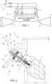
figure 1 is a simplified block diagram of a gas turbine engine in accordance with an embodiment of the present invention; -
figure 2 is a cross sectional lateral view of part of a combustor assembly of the gas turbine engine offigure 1 , with parts removed for clarity; -
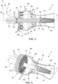
figure 3 is a cross-sectional lateral view, cut along a longitudinal axial plane, of a component of the combustor assembly offigure 2 ; -
figure 4 is a perspective view of the component offigure 3 , partially cut along a longitudinal axial plane; -
figure 5 is a cross-sectional lateral view of an enlarged detail of the component offigure 3 ; -
figure 6 is a cross-sectional lateral view of an enlarged detail of the component offigure 3 , in accordance with a different embodiment of the present invention; and -
figure 7 is a cross sectional lateral view of part of a combustor assembly of a gas turbine engine in accordance with another embodiment of the present invention, with parts removed for clarity. - With reference to
Figure 1 , a gas turbine engine in accordance with an embodiment of the present invention is indicated by numeral 1 and comprises acompressor 2, acombustor assembly 3 and an expansion section orturbine 5. - The axial-
type compressor 2 feeds thecombustor assembly 3 with a flow of air drawn from outside. - The
combustor assembly 3 comprises a plurality of two-stagesequential combustors 6 and a commonannular combustion chamber 7. Thecombustors 6 receive a fuel flowrate from one or more fuel sources, e.g. afuel supply system 8 with afirst fuel line 8a and asecond fuel line 8b, and cause the combustion of a mixture of air and fuel. The fuel may be, by way of non-limiting example, natural gas, syngas, hydrogen, methane or ammonia. Moreover, thefirst fuel line 8a and thesecond fuel line 8b may supply both the same fuel or respective different types of fuel. - The
turbine 7 receives and expands the flow exhaust gas from thecombustor assembly 3 to extract mechanical work, which is transferred to an external user, typically an electric generator, here not shown. - Part of the
combustor assembly 3, including one of thecombustors 6, is illustrated in greater detail infigure 2 . Thecombustor 6 is also shown in isolation infigures 3 and 4 . It is herein understood that all theburners 6 have the identical structure. - The
annular combustion chamber 7 is housed incombustion chamber casing 10 of the gas turbine engine 1. Thecombustion chamber casing 10 defines acommon air plenum 11 around theannular combustion chamber 7 and is coupled to thecompressor 2 to receive a flow of compressed air. Compressed air is then supplied to the burners. - The
combustors 6 are circumferentially distributed around theannular combustion chamber 7 and are in fluid communication with the interior thereof throughrespective coupling ports 13. In one embodiment, thecombustors 6 are secured to the combustion chamber casing 10 by mountingplates 14 through mountingports 15 in thecombustion chamber casing 10. The mountingplates 14 seal the mountingports 15, so that air is fed to thecombustors 6 only from thecommon plenum 11. Thecombustors 6 are housed in thecommon air plenum 11, between the combustion chamber casing 10 and theannular combustion chamber 7. The mountingplates 14 and the mountingports 15 allow connection of thecombustor 6 to thefuel supply system 8. - With reference to
figures 3 and 4 , eachcombustor 6 comprises acombustor casing 18, extending along a combustor axis C and delimiting a respectivegas flow path 20. Therefore, thegas flow path 20 of eachcombustor 6 is separated from thegas flow paths 20 of theother combustors 6 upstream of theannular combustion chamber 7. A supportingplate 21 is arranged to close an upstream end of thecombustor casing 18. In one embodiment, thecombustor casing 18 has acylindrical portion 18a, adjacent to the supportingplate 21, an intermediateconvergent portion 18b and an enddivergent portion 18c. - Each
combustor 6 also comprises afirst combustor stage 6a and asecond combustor stage 6b, sequentially arranged along the respectivegas flow path 20, and afuel plenum 22, in the form of a ring arranged coaxially to thefirst combustor stage 6a and tosecond combustor stage 6b. - The
first combustor stage 6a of each combustor comprises a plurality ofrespective microburners 23 supported by the supportingplate 21 and distributed around the respective combustor axis C. - As illustrated in
figure 5 , eachmicroburner 23 comprises afuel conduit 24 and anair conduit 25 coaxially arranged and formingfirst stage nozzles 27 at anozzle surface 21a of the respective supportingplate 21 adjacent to thegas flow path 20. The number offirst stage nozzles 27 is selected such that the nozzle surfaces 21a of the supportingplates 21 have a density offirst stage nozzles 27 between 50 nozzles/m2 and 300 nozzles/m2. - In the embodiment of
figures 3-5 , all themicroburners 23 have therespective fuel conduits 24 coupled to thefuel plenum 22 of therespective combustor 6. In another embodiment (figure 6 ), in eachcombustor 6microburners 23 of a group of have therespective fuel conduits 24 coupled to thefuel plenum 22, whereasmicroburners 23 of another group are decoupled from thefuel plenum 22, thus simply defining air passages. Thefuel plenum 22 is in turn coupled to thefirst fuel line 8a of thefuel supply system 8 through afirst stage valve 26. Theair conduits 25 are spaced apart from thefuel plenum 22, so that air may be fed to themicroburners 23 through passages between thefuel plenum 22. Themicroburners 23 are configured to create flames at a short distance from the nozzle surfaces 21a and turbulence created by air and fuel flows leaving thefirst stage nozzles 27 favors mixing. Themicroburners 23 may be designed so that first stage flames are confined substantially to thecylindrical portion 18a of thecombustor casing 18, where a reaction zone is defined. - The
second combustor stages 6b of thecombustors 6 are configured to discharge into theannular combustion chamber 7. Therefore, theannular combustion chamber 7 defines a common combustion chamber for thesecond combustor stages 6b of thecombustors 6. - Each
combustor 6 also comprises acentral lance injector 28, extending through the respective supportingplate 21 andfuel plenum 22 into thecombustor casing 18, up to the respectivesecond combustor stage 6b, in the enddivergent portion 18c of thecombustor casing 18. Eachcentral lance injector 28 comprises aninner fuel conduit 30 coupled to thesecond fuel line 8b of thefuel supply system 8 through respectivesecond stage valves 31. Thecentral lance injector 28 hasair inlets 32 circumferentially arranged upstream of the supportingplate 21 andsecond stage nozzles 33 supplied by theinner fuel conduit 30 and configured to deliver fuel into thegas flow path 20 at the second stage combustor. In one embodiment, thesecond stage nozzles 33 may be configured to deliver fuel into thegas flow path 20 substantially in a radial, crossflow direction. - Each
combustor 6 comprises adilution air mixer 35, configured to introduce air for the purpose of sequential combustion into thegas flow path 20, at a location between thefirst combustor stage 6a and thesecond combustor stage 6b. Thedilution air mixer 35 includes mixingopenings 36 in the intermediateconvergent portion 18b of therespective combustor 6. The mixingopenings 36 allow to introduce dilution air into thegas flow path 20 of thecombustors 6 directly from thecommon air plenum 11. - A different embodiment of the invention is illustrated in
figure 7 , where parts identical to parts already described are indicated by the same reference numbers. In this embodiment, agas turbine engine 100 comprises thecompressor 2, acombustor assembly 103 and the expansion section orturbine 5. - The
combustor assembly 103 comprises the commonannular combustion chamber 7 and a plurality of two-stagesequential combustors 106 circumferentially distributed around theannular combustion chamber 7 and communicating with theannular combustion chamber 7 through thecoupling ports 13. - Each
sequential combustors 106 comprises afirst combustor stage 106a, asecond combustor stage 106b, atransition duct 107 and adilution air mixer 135. Thefirst combustor stage 106a, thetransition duct 107 and thedilution air mixer 135 are housed in a combustor casing 118 outside the combustion chamber casing 10, whereas thesecond combustor stage 106b is accommodated in thecommon plenum 11. The combustor casing 118 has afirst portion 118a and asecond portion 118b joined to each other byflanges first portion 118a of the combustor casing 118 houses thefirst combustor stage 106a and forms alocal air plenum 122, coupled to thecommon plenum 11 and receiving compressed air through apiping system 121 arranged externally to thecombustion chamber casing 10. Thesecond portion 118b of the combustor casing 118 houses thetransition duct 107 and thedilution air mixer 135. - The
first stage combustor 106a and thesecond stage combustor 106b are sequentially arranged along a respectivegas flow path 120, that is also defined through thetransition duct 107 and thedilution air mixer 135. - The
first stage combustor 106a comprises acentral burner 123 housed in thefirst portion 118a of the respective combustor casing 118 and configured to feed mixture of fuel and air into thetransition duct 107, where a reaction zone is defined. - The
dilution air mixer 135 is arranged downstream of thetransition duct 107 and is configured to introduce air into thegas flow path 120 from thecommon air plenum 11 through a respective mountingport 15. - The
second combustor stage 106b is housed in thecommon air plenum 11, between the combustion chamber casing 10 and theannular combustion chamber 7. Thesecond combustor stage 106b is directly coupled to theannular combustion chamber 7 through arespective coupling port 13. - Finally, it is clear that modifications and variants may be made to the gas turbine engine described herein without departing from the scope of the present invention, as defined in the appended claims.
Claims (15)
- A gas turbine engine comprising:an annular combustion chamber (7);a plurality of combustors (6) communicating with the annular combustion chamber (7), wherein each combustor (6) defines a respective gas flow path (20) along a respective combustor axis (C) and comprises a first combustor stage (6a) and a second combustor stage (6b), sequentially arranged along the respective gas flow path (20), and wherein the second combustor stages (6b) of the combustors (6) are configured to discharge into the annular combustion chamber (7) .
- The gas turbine engine according to claim 1, wherein the gas flow path (20) of each combustor (6) is separated from the gas flow paths (20) of the other combustors (6) upstream of the annular combustion chamber (7).
- The gas turbine engine according to claim 1 or 2, wherein the annular combustion chamber (7) defines a common combustion chamber for the second combustor stages (6b) of the combustors (6).
- The gas turbine engine according to any one of the preceding claims, wherein the first combustor stage (6a) of each combustor (6) comprises a plurality of respective microburners (23) distributed around the respective combustor axis (C).
- The gas turbine engine according to claim 4, wherein each combustor (6) comprises a combustor casing (18), delimiting the respective gas flow path (20), and a supporting plate (21) arranged to close an upstream end of the combustor casing (18) and supporting the microburners (23) of the respective combustor (6), and wherein each microburner (23) comprises a fuel conduit (24) and an air conduit (25) forming first stage nozzles (27) at a nozzle surface (21a) of the respective supporting plate (21) adjacent to the gas flow path (20).
- The gas turbine engine according to claim 5, wherein each nozzle surface (21a) has a density of first stage nozzles (27) between 50 nozzles/m2 and 300 nozzles/m2.
- The gas turbine engine according to claim 5 or 6, wherein each combustor (6) comprises a fuel plenum (22) and wherein in each combustor (6) the microburners (23) of at least a first group of microburners (23) have the respective fuel conduits (24) coupled to the fuel plenum (22) of the respective combustor (6).
- The gas turbine engine according to claim 7, wherein in each combustor (6) all the microburners (23) have the respective fuel conduits (24) coupled to the fuel plenum (22) of the respective combustor (6) or the microburners (23) of a second group of microburners (23) are decoupled from the fuel plenum (22) of the respective combustor (6).
- The gas turbine engine according to any one of claims 5 to 8, wherein each combustor (6) comprises a central lance injector (28) extending through the respective supporting plate (21) up to the respective second combustor stage (6b).
- The gas turbine engine according to claim 9, comprising a fuel supply system (8), wherein each central lance injector (28) comprises an inner fuel conduit (30) coupled to the fuel supply system (8) and second stage nozzles supplied by the inner fuel conduit (30) and configured to deliver fuel into the gas flow path (20) at the second stage combustor (6).
- The gas turbine engine according to any one of claims 4 to 10, wherein each combustor (6; 106) comprises a dilution air mixer (35; 135), configured to introduce air into the gas flow path (20; 120) at a location between the first combustor stage (6a; 106a) and the second combustor stage (6b; 106b).
- The gas turbine engine according to claim 11, comprising a compressor (2) and a combustion chamber casing (10), defining a common air plenum (11) configured to receive compressed air from the compressor (2) and to supply the compressed air to the combustors (6).
- The gas turbine engine according to claim 12, wherein the combustors (6) are housed in the common air plenum, between the combustion chamber casing and the annular combustion chamber (7), the combustors (6) being preferably configured to receive air directly from the common air plenum.
- The gas turbine engine according to claim 12, wherein each combustor (106) comprises a combustor casing (118), having a first portion (118a) and a second portion (118b), wherein each first stage combustor (106) comprises a central burner (123) housed in the first portion (118a) of the respective combustor casing (118) and the first portion (118a) of the combustor casing (118) defines a local air (122) plenum for the first stage combustor (106), and wherein the local air plena (122) are configured to receive air from the common air plenum (11) through respective piping systems (121) .
- The gas turbine engine according to claim 14, wherein each combustor (106) comprises a transition duct (107), housed in the second portion (118b) of the respective combustor casing (118) between the respective first combustor stage (106a) and the respective second combustor stage (106b), wherein the dilution air mixer (135) of each combustor (106) is housed in the second portion (118b) of the respective combustor casing (118) and is configured to introduce air into the gas flow path (20) from the common air plenum (11) through a respective port (15) in the combustion chamber casing (10), and wherein the second combustor stage (6b) of the combustors (106) is housed in the common air plenum (11), between the combustion chamber casing (10) and the annular combustion chamber (7).
Priority Applications (2)
| Application Number | Priority Date | Filing Date | Title |
|---|---|---|---|
| EP22217343.7A EP4394253B1 (en) | 2022-12-30 | 2022-12-30 | Gas turbine engine |
| CN202311611407.3A CN118273816A (en) | 2022-12-30 | 2023-11-29 | Gas turbine engine |
Applications Claiming Priority (1)
| Application Number | Priority Date | Filing Date | Title |
|---|---|---|---|
| EP22217343.7A EP4394253B1 (en) | 2022-12-30 | 2022-12-30 | Gas turbine engine |
Publications (2)
| Publication Number | Publication Date |
|---|---|
| EP4394253A1 true EP4394253A1 (en) | 2024-07-03 |
| EP4394253B1 EP4394253B1 (en) | 2026-02-18 |
Family
ID=84767136
Family Applications (1)
| Application Number | Title | Priority Date | Filing Date |
|---|---|---|---|
| EP22217343.7A Active EP4394253B1 (en) | 2022-12-30 | 2022-12-30 | Gas turbine engine |
Country Status (2)
| Country | Link |
|---|---|
| EP (1) | EP4394253B1 (en) |
| CN (1) | CN118273816A (en) |
Citations (5)
| Publication number | Priority date | Publication date | Assignee | Title |
|---|---|---|---|---|
| US6374594B1 (en) * | 2000-07-12 | 2002-04-23 | Power Systems Mfg., Llc | Silo/can-annular low emissions combustor |
| US20020157400A1 (en) * | 2001-04-27 | 2002-10-31 | Siemens Aktiengesellschaft | Gas turbine with combined can-type and annular combustor and method of operating a gas turbine |
| US20160123597A1 (en) * | 2014-10-31 | 2016-05-05 | Alstom Technology Ltd | Combustor arrangement for a gas turbine |
| EP3367001A1 (en) * | 2017-02-28 | 2018-08-29 | Ansaldo Energia Switzerland AG | Second-stage combustor for a sequential combustor of a gas turbine |
| US20210301722A1 (en) * | 2020-03-30 | 2021-09-30 | General Electric Company | Compact turbomachine combustor |
-
2022
- 2022-12-30 EP EP22217343.7A patent/EP4394253B1/en active Active
-
2023
- 2023-11-29 CN CN202311611407.3A patent/CN118273816A/en active Pending
Patent Citations (5)
| Publication number | Priority date | Publication date | Assignee | Title |
|---|---|---|---|---|
| US6374594B1 (en) * | 2000-07-12 | 2002-04-23 | Power Systems Mfg., Llc | Silo/can-annular low emissions combustor |
| US20020157400A1 (en) * | 2001-04-27 | 2002-10-31 | Siemens Aktiengesellschaft | Gas turbine with combined can-type and annular combustor and method of operating a gas turbine |
| US20160123597A1 (en) * | 2014-10-31 | 2016-05-05 | Alstom Technology Ltd | Combustor arrangement for a gas turbine |
| EP3367001A1 (en) * | 2017-02-28 | 2018-08-29 | Ansaldo Energia Switzerland AG | Second-stage combustor for a sequential combustor of a gas turbine |
| US20210301722A1 (en) * | 2020-03-30 | 2021-09-30 | General Electric Company | Compact turbomachine combustor |
Also Published As
| Publication number | Publication date |
|---|---|
| EP4394253B1 (en) | 2026-02-18 |
| CN118273816A (en) | 2024-07-02 |
Similar Documents
| Publication | Publication Date | Title |
|---|---|---|
| CN1763434B (en) | Low cost dual fuel combustor and related methods | |
| US11287134B2 (en) | Combustor with dual pressure premixing nozzles | |
| CN101008497B (en) | Independent pilot fuel control in secondary fuel nozzle | |
| US20190162414A1 (en) | Gas turbine combustor | |
| US5351474A (en) | Combustor external air staging device | |
| US6848260B2 (en) | Premixed pilot burner for a combustion turbine engine | |
| EP1058063B1 (en) | Liquid fuel injector for burners in gas turbines | |
| US6968693B2 (en) | Method and apparatus for reducing gas turbine engine emissions | |
| US7690203B2 (en) | Removable diffusion stage for gas turbine engine fuel nozzle assemblages | |
| CN102597631B (en) | Combustors especially for gas turbines | |
| CN104246371A (en) | Turbomachine combustor assembly | |
| RU2535433C2 (en) | Guide vane, burner and gas turbine | |
| US20040123597A1 (en) | Secondary fuel nozzle with readily customizable pilot fuel flow rate | |
| JP2012526261A (en) | Multi premixer fuel nozzle | |
| JP2021096016A (en) | Gas turbine combustor | |
| EP4394253B1 (en) | Gas turbine engine | |
| CN116379472A (en) | Burner Assemblies with Inline Injectors | |
| CN102788369B (en) | Adaptive Combustor Fuel Nozzles | |
| RU2533045C2 (en) | Burner, namely for gas turbines | |
| US20240263786A1 (en) | Central air passage with radial fuel distributor | |
| CN116293797B (en) | Burner with fuel injector | |
| US10955141B2 (en) | Dual-fuel fuel nozzle with gas and liquid fuel capability | |
| WO2023188984A1 (en) | Combustor and gas turbine | |
| RU89671U1 (en) | BURNER DEVICE FOR COMBUSTION CHAMBER OF A GAS-TURBINE INSTALLATION | |
| EP3637000A1 (en) | Gas turbine burner for reactive fuels |
Legal Events
| Date | Code | Title | Description |
|---|---|---|---|
| PUAI | Public reference made under article 153(3) epc to a published international application that has entered the european phase |
Free format text: ORIGINAL CODE: 0009012 |
|
| STAA | Information on the status of an ep patent application or granted ep patent |
Free format text: STATUS: THE APPLICATION HAS BEEN PUBLISHED |
|
| AK | Designated contracting states |
Kind code of ref document: A1 Designated state(s): AL AT BE BG CH CY CZ DE DK EE ES FI FR GB GR HR HU IE IS IT LI LT LU LV MC ME MK MT NL NO PL PT RO RS SE SI SK SM TR |
|
| STAA | Information on the status of an ep patent application or granted ep patent |
Free format text: STATUS: REQUEST FOR EXAMINATION WAS MADE |
|
| 17P | Request for examination filed |
Effective date: 20250102 |
|
| GRAP | Despatch of communication of intention to grant a patent |
Free format text: ORIGINAL CODE: EPIDOSNIGR1 |
|
| STAA | Information on the status of an ep patent application or granted ep patent |
Free format text: STATUS: GRANT OF PATENT IS INTENDED |
|
| INTG | Intention to grant announced |
Effective date: 20250915 |
|
| GRAS | Grant fee paid |
Free format text: ORIGINAL CODE: EPIDOSNIGR3 |
|
| P01 | Opt-out of the competence of the unified patent court (upc) registered |
Free format text: CASE NUMBER: UPC_APP_0015695_4394253/2025 Effective date: 20251203 |
|
| GRAA | (expected) grant |
Free format text: ORIGINAL CODE: 0009210 |
|
| STAA | Information on the status of an ep patent application or granted ep patent |
Free format text: STATUS: THE PATENT HAS BEEN GRANTED |
|
| AK | Designated contracting states |
Kind code of ref document: B1 Designated state(s): AL AT BE BG CH CY CZ DE DK EE ES FI FR GB GR HR HU IE IS IT LI LT LU LV MC ME MK MT NL NO PL PT RO RS SE SI SK SM TR |
|
| REG | Reference to a national code |
Ref country code: CH Ref legal event code: F10 Free format text: ST27 STATUS EVENT CODE: U-0-0-F10-F00 (AS PROVIDED BY THE NATIONAL OFFICE) Effective date: 20260218 Ref country code: GB Ref legal event code: FG4D |
|
| REG | Reference to a national code |
Ref country code: IE Ref legal event code: FG4D |
|
| REG | Reference to a national code |
Ref country code: DE Ref legal event code: R096 Ref document number: 602022030557 Country of ref document: DE |