EP4394252A1 - Method for controlling a sequential combustor of a gas turbine engine and gas turbine power plant - Google Patents
Method for controlling a sequential combustor of a gas turbine engine and gas turbine power plant Download PDFInfo
- Publication number
- EP4394252A1 EP4394252A1 EP22217311.4A EP22217311A EP4394252A1 EP 4394252 A1 EP4394252 A1 EP 4394252A1 EP 22217311 A EP22217311 A EP 22217311A EP 4394252 A1 EP4394252 A1 EP 4394252A1
- Authority
- EP
- European Patent Office
- Prior art keywords
- fuel
- combustor
- stage
- air
- ammonia
- Prior art date
- Legal status (The legal status is an assumption and is not a legal conclusion. Google has not performed a legal analysis and makes no representation as to the accuracy of the status listed.)
- Granted
Links
Images


Classifications
-
- F—MECHANICAL ENGINEERING; LIGHTING; HEATING; WEAPONS; BLASTING
- F23—COMBUSTION APPARATUS; COMBUSTION PROCESSES
- F23R—GENERATING COMBUSTION PRODUCTS OF HIGH PRESSURE OR HIGH VELOCITY, e.g. GAS-TURBINE COMBUSTION CHAMBERS
- F23R3/00—Continuous combustion chambers using liquid or gaseous fuel
- F23R3/28—Continuous combustion chambers using liquid or gaseous fuel characterised by the fuel supply
- F23R3/34—Feeding into different combustion zones
- F23R3/346—Feeding into different combustion zones for staged combustion
-
- F—MECHANICAL ENGINEERING; LIGHTING; HEATING; WEAPONS; BLASTING
- F02—COMBUSTION ENGINES; HOT-GAS OR COMBUSTION-PRODUCT ENGINE PLANTS
- F02C—GAS-TURBINE PLANTS; AIR INTAKES FOR JET-PROPULSION PLANTS; CONTROLLING FUEL SUPPLY IN AIR-BREATHING JET-PROPULSION PLANTS
- F02C9/00—Controlling gas-turbine plants; Controlling fuel supply in air- breathing jet-propulsion plants
- F02C9/26—Control of fuel supply
-
- F—MECHANICAL ENGINEERING; LIGHTING; HEATING; WEAPONS; BLASTING
- F23—COMBUSTION APPARATUS; COMBUSTION PROCESSES
- F23C—METHODS OR APPARATUS FOR COMBUSTION USING FLUID FUEL OR SOLID FUEL SUSPENDED IN A CARRIER GAS OR AIR
- F23C6/00—Combustion apparatus characterised by the combination of two or more combustion chambers or combustion zones, e.g. for staged combustion
- F23C6/04—Combustion apparatus characterised by the combination of two or more combustion chambers or combustion zones, e.g. for staged combustion in series connection
- F23C6/045—Combustion apparatus characterised by the combination of two or more combustion chambers or combustion zones, e.g. for staged combustion in series connection with staged combustion in a single enclosure
- F23C6/047—Combustion apparatus characterised by the combination of two or more combustion chambers or combustion zones, e.g. for staged combustion in series connection with staged combustion in a single enclosure with fuel supply in stages
-
- F—MECHANICAL ENGINEERING; LIGHTING; HEATING; WEAPONS; BLASTING
- F23—COMBUSTION APPARATUS; COMBUSTION PROCESSES
- F23R—GENERATING COMBUSTION PRODUCTS OF HIGH PRESSURE OR HIGH VELOCITY, e.g. GAS-TURBINE COMBUSTION CHAMBERS
- F23R3/00—Continuous combustion chambers using liquid or gaseous fuel
- F23R3/02—Continuous combustion chambers using liquid or gaseous fuel characterised by the air-flow or gas-flow configuration
- F23R3/26—Controlling the air flow
-
- F—MECHANICAL ENGINEERING; LIGHTING; HEATING; WEAPONS; BLASTING
- F23—COMBUSTION APPARATUS; COMBUSTION PROCESSES
- F23R—GENERATING COMBUSTION PRODUCTS OF HIGH PRESSURE OR HIGH VELOCITY, e.g. GAS-TURBINE COMBUSTION CHAMBERS
- F23R3/00—Continuous combustion chambers using liquid or gaseous fuel
- F23R3/28—Continuous combustion chambers using liquid or gaseous fuel characterised by the fuel supply
- F23R3/36—Supply of different fuels
-
- F—MECHANICAL ENGINEERING; LIGHTING; HEATING; WEAPONS; BLASTING
- F23—COMBUSTION APPARATUS; COMBUSTION PROCESSES
- F23R—GENERATING COMBUSTION PRODUCTS OF HIGH PRESSURE OR HIGH VELOCITY, e.g. GAS-TURBINE COMBUSTION CHAMBERS
- F23R2900/00—Special features of, or arrangements for continuous combustion chambers; Combustion processes therefor
- F23R2900/00002—Gas turbine combustors adapted for fuels having low heating value [LHV]
-
- F—MECHANICAL ENGINEERING; LIGHTING; HEATING; WEAPONS; BLASTING
- F23—COMBUSTION APPARATUS; COMBUSTION PROCESSES
- F23R—GENERATING COMBUSTION PRODUCTS OF HIGH PRESSURE OR HIGH VELOCITY, e.g. GAS-TURBINE COMBUSTION CHAMBERS
- F23R2900/00—Special features of, or arrangements for continuous combustion chambers; Combustion processes therefor
- F23R2900/03341—Sequential combustion chambers or burners
Definitions
- Heat in the first combustor stage causes the residual ammonia which has not taken part to first stage combustion to be thermally decomposed into molecular nitrogen N 2 and molecular hydrogen H 2 , which are available to resume combustion in the presence of additional oxygen.
- Injection of dilution air at a location where molecular ammonia has been decomposed and is no longer present, or is present in a negligible amount determines the conditions for resuming the combustion without causing critical production of NOx. Together with control of the amount of the first fuel supplied to the first combustor stage combustion, injection of dilution air allows also to control the temperature of the gas at the inlet of the second combustor stage.
- a conventional fuel such as natural gas or syngas, may be used in the second combustor stage of the sequential combustor for hybrid operation of the gas turbine engine.
- the method comprises controlling a temperature of a first stage flame, an equivalence ratio of the first stage and a fuel massflow of the first stage so that the second air/fuel mixture is auto-ignited in the second combustor stage.
- a content of the first air/fuel mixture is entirely ammonia.
- the gas turbine power plant comprises a mixer configured to add dilution air along a flow path between the first combustor stage and the second combustor stage, at a location where unburnt ammonia from the first combustor stage is decomposed.
- the second fuel source comprises a reactor coupled to the first fuel source to receive the first fuel and configured to decompose ammonia in the first fuel and to feed the decomposed ammonia to the second combustor stage as the second fuel.
- the second fuel contains at least one of hydrogen, methane, ethane, propane, butane, pentane or any other gaseous fuel.
- the second air/fuel mixture is over-stoichiometric.
- number 1 defines a gas-turbine plant as a whole comprising a gas turbine engine 2, a first fuel supply line 3, second fuel supply line 4 a control system 5.
- the control system 5 is configured to determine set-points of the gas turbine engine 2 for desired operating conditions and to use actuators of the gas turbine engine 2, so that set-points may be achieved.
- the compressor 6 feeds the combustor assembly 7 with a flow of air drawn from outside.
- the turbine 8 receives and expands a flow of burnt hot gas from the combustor assembly 7 to extract mechanical work, which is transferred to an external user, typically an electric generator, which is not shown here.
- the first supply line 3 supplies a first fuel F1, which contains molecular ammonia and in one embodiment is sole ammonia.
- the second supply line 4 supplies a second fuel F2, which contains one of hydrogen and methane or a mixture thereof.
- the second fuel F2 may be natural gas or syngas and contain one or more of ethane, propane, butane, pentane or any other gaseous fuel.
- Figure 2 schematically shows one of the sequential combustors 10, being it understood that the other sequential combustors 10 have basically an identical structure.
- the sequential combustor 10 comprises a first combustor stage 12 and a second combustor stage 13, sequentially arranged along a gas flow path 15.
- a mixer 16 is arranged along the gas flow path 15 between the first combustor stage 12 and the second combustor stage 13 and is configured to add a controlled amount of dilution air A into gas flowing through the gas flow path 15.
- the first combustor stage 12 is fluidly coupled to the first fuel supply line 3 to receive an amount of the first fuel F1, which is adjustable by a first stage fuel actuator 18, e.g. a fuel valve system.
- the first combustor stage 12 also receives an airflow from the plenum 11, which is in turn fed by the compressor 6.
- the first fuel F1 and the airflow from the plenum 11 form a first air/fuel mixture M1 which is burned in the first combustor stage 12.
- the amount of first fuel F1 is controlled by the control system 5 through the first stage fuel actuator 18 so that the first air/fuel mixture M1 is stoichiometric or sub-stoichiometric (rich) for the first fuel F1.
- a gas-turbine plant 100 comprises the gas turbine engine 2, the (first and here sole) fuel supply line 3, which supplies the first fuel F1 containing molecular ammonia and, in one embodiment, only ammonia, and the control system 5 as already described. Additionally, the gas-turbine plant 100 comprises a reactor or ammonia cracker 104 coupled to the fuel source 3 and configured to decompose ammonia into molecular nitrogen N 2 and molecular hydrogen H 2 .
- the ammonia cracker 104 is coupled to the fuel source 3 to receive a second fraction of the first fuel F1 from the supply line 3 and to the second combustor stage 13 to supply the second fuel F2. Specifically, the ammonia cracker 104 decomposes the molecular ammonia contained in the received flow of the first fuel F into molecular nitrogen N 2 and molecular hydrogen H 2 . The ammonia cracker 104 supplies the decomposed ammonia to the second combustor stage 13 as the second fuel F2 to form the second air/fuel mixture M2 with exhaust from the first combustor stage 12 and dilution air A provided by the mixer 16.
- control system 5 also controls at least one of a temperature of a first stage flame in the first combustor stage 12, an equivalence ratio of the first stage and a fuel massflow of the first stage and the feed of the dilution air A through the mixer 16 so that the second air/fuel mixture M2 is auto-ignited in the second combustor stage 13 and a flame front position of the second combustor stage 13 is adjusted as desired.
- a gas-turbine plant 200 comprises the gas turbine engine 2, the first fuel supply line 3, which supplies the first fuel F1 containing molecular ammonia, the second supply line 4, which supplies a fuel flow containing hydrogen, methane ethane, propane, butane, pentane or any other gaseous fuel, the control system 5 and, in addition, a reactor or ammonia cracker 204 coupled to the fuel source 3 and configured to decompose ammonia into molecular nitrogen N 2 and molecular hydrogen H 2 .
- the second combustor stage 13 may receive the second fuel F2 either from the second supply line 4 or from the ammonia cracker 204, or even from both.
- the control system 5 controls the supply of the second fuel F2 through second stage fuel actuators 19, 219 so that the second air/fuel mixture M2 is over-stoichiometric, is auto-ignited in the second combustor stage 13 and a flame front position of the second combustor stage 13 is adjusted as desired.
Landscapes
- Engineering & Computer Science (AREA)
- Chemical & Material Sciences (AREA)
- Combustion & Propulsion (AREA)
- Mechanical Engineering (AREA)
- General Engineering & Computer Science (AREA)
Abstract
Description
- The present invention relates to a method for controlling a sequential combustor of a gas turbine engine and to a gas turbine power plant.
- As is known, ammonia is a promising fuel that may be used to run gas turbine engines and provide a strong contribution to decarbonization. Combustion of ammonia is in fact completely carbon free, on the one side, and, on the other side, ammonia is an energy dense fuel suitable for efficient and durable storage of large amounts of chemical energy. Required volume may be remarkably low, for example compared to hydrogen, because ammonia is rather easy to liquefy and can be kept in the liquid state under relatively low pressure even at environmental temperature. Thus, not only storage, but also transportation and distribution may be made efficient, safe and cost-effective.
- However, combustion of ammonia in ordinary operating conditions of gas turbine engines is known to produce significant amounts of nitrogen oxides (NOx). Emissions of NOx are critical and need to be minimized as well as emissions of carbon monoxide. Also blends of ammonia and carbon based fuels such as natural gas or methane may not meet current strict requirements for NOx emissions if directly supplied to gas turbine engines. The benefit of carbon free or at least low-carbon combustion may be thus cancelled by a corresponding increase in NOx emissions.
- Moreover, reactivity of ammonia is relatively low and represents another hurdle that makes use of ammonia in gas turbine engines difficult.
- In other words, gas turbine engines as normally operated are not compatible with feed of ammonia as the sole fuel or as a component of a mixture of different fuels.
- It is an aim of the present invention to provide a method for controlling a sequential combustor of a gas turbine engine and a gas turbine power plant that allow the above limitations to be overcome or at least reduced.
- According to the present invention, there is provided a method for controlling a sequential combustor of a gas turbine engine, the sequential combustor comprising a first combustor stage and a second stage;
- the method comprising supplying the first combustor stage of the sequential combustor with a first air/fuel mixture (M1) and supplying the second stage of the sequential combustor with a second air/fuel mixture;
- the first air/fuel mixture contains ammonia and is stoichiometric or sub-stoichiometric.
- The supply of an excess of ammonia with respect to air oxygen prevents or at least strongly reduces the formation of nitrogen dioxides, which is instead a major problem in conventional engines operated on lean air/fuel mixtures containing ammonia. Moreover, residual ammonia is thermally decomposed into molecular nitrogen N2 and molecular hydrogen H2, which are therefore suitable for resuming the combustion without increasing the production of NOx.
- The solution thus allows to exploit advantages of ammonia as a fuel for gas turbine engines and its potential contribution to decarbonization, without incurring in adverse effects such as high NOx emission levels. Advantages of ammonia to other carbon-free fuels mainly reside in ease of storage and transportation in amounts sufficient to meet the need of the market.
- According to an aspect of the invention, a fuel content of the first air/fuel mixture is entirely ammonia.
- Completely carbon-free combustion is thus ensured, without the drawbacks associated with supplying other fuels which are not as easy and safe to store and distribute as ammonia (e.g. direct supply of molecular hydrogen).
- According to an aspect of the invention, the method comprises supplying dilution air into the sequential combustor between the first combustor stage and the second stage, at a location where unburnt ammonia from the first combustor stage is decomposed.
- Heat in the first combustor stage causes the residual ammonia which has not taken part to first stage combustion to be thermally decomposed into molecular nitrogen N2 and molecular hydrogen H2, which are available to resume combustion in the presence of additional oxygen. Injection of dilution air at a location where molecular ammonia has been decomposed and is no longer present, or is present in a negligible amount, determines the conditions for resuming the combustion without causing critical production of NOx. Together with control of the amount of the first fuel supplied to the first combustor stage combustion, injection of dilution air allows also to control the temperature of the gas at the inlet of the second combustor stage.
- According to an aspect of the invention, the method comprises decomposing additional ammonia outside the sequential combustor.
- According to an aspect of the invention, the method comprises supplying the decomposed additional ammonia to the second combustor stage in the second air/fuel mixture.
- Decomposition of additional ammonia outside the sequential combustor and feed of such decomposed additional ammonia to the second combustor stage create the conditions for running the gas turbine engine on ammonia alone, if so desired, without incurring in excessive production of NOx.
- According to an aspect of the invention, the second air/fuel mixture contains at least one of hydrogen, methane, ethane, propane, butane pentane and any other gaseous fuel.
- A conventional fuel, such as natural gas or syngas, may be used in the second combustor stage of the sequential combustor for hybrid operation of the gas turbine engine.
- According to an aspect of the invention, the second air/fuel mixture (M2) is over-stoichiometric (lean).
- If hydrocarbons are present in the second fuel (e.g. natural gas or syngas), the excess of oxygen allows to keep production of carbon monoxide very low. Instead, in case products of ammonia decomposition are burned, the absence of molecular ammonia prevents critical production of NOx even in a lean air/fuel mixture.
- According to an aspect of the invention, the method comprises controlling a temperature of a first stage flame, an equivalence ratio of the first stage and a fuel massflow of the first stage so that the second air/fuel mixture is auto-ignited in the second combustor stage.
- According to the present invention, there is also provided a gas turbine power plant comprising:
- a gas turbine engine, provided with a sequential combustor having a first combustor stage and a second combustor stage;
- a first fuel source coupled to the first combustor stage and providing a first fuel;
- a second fuel source coupled to the second combustor stage and providing a second fuel;
- a control system, configured to control fuel supply to the first combustor stage and to the second combustor stage, whereby a first air/fuel mixture containing the first fuel is supplied to the first combustor stage and a second air/fuel mixture containing the second fuel is supplied to the second combustor stage;
- wherein the first fuel contains ammonia and the control system is configured to control supply of the first fuel so that the first air/fuel mixture is stoichiometric or sub-stoichiometric.
- According to an aspect of the invention, a content of the first air/fuel mixture is entirely ammonia.
- According to an aspect of the invention, the gas turbine power plant comprises a mixer configured to add dilution air along a flow path between the first combustor stage and the second combustor stage, at a location where unburnt ammonia from the first combustor stage is decomposed.
- According to an aspect of the invention, the second fuel source comprises a reactor coupled to the first fuel source to receive the first fuel and configured to decompose ammonia in the first fuel and to feed the decomposed ammonia to the second combustor stage as the second fuel.
- According to an aspect of the invention, the second fuel contains at least one of hydrogen, methane, ethane, propane, butane, pentane or any other gaseous fuel.
- According to an aspect of the invention, the second air/fuel mixture is over-stoichiometric.
- According to an aspect of the invention, the control system is configured to control at least one of a temperature of a first stage flame, an equivalence ratio of the first stage and a fuel massflow of the first stage so that the second air/fuel mixture is auto-ignited in the second combustor stage.
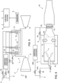
- The present invention will now be described with reference to the accompanying drawings, which show a number of non-limitative embodiments thereof, in which:
-
figure 1 is a simplified block diagram of a gas turbine engine in accordance with an embodiment of the present invention; -
figure 2 is a schematic view of a portion of the gas turbine engine offigure 1 ; -
figure 3 is a simplified block diagram of a gas turbine engine in accordance with another embodiment of the present invention; -
figure 4 is a schematic view of a portion of the gas turbine engine offigure 3 ; -
figure 5 is a simplified block diagram of a gas turbine engine in accordance with a further embodiment of the present invention; -
figure 6 is a schematic view of a portion of the gas turbine engine offigure 5 . - In the following, when dealing with mixtures of fuel and air, reference will be made to the air-to-fuel ratio λ. Therefore, the terms "sub-stoichiometric" and "over-stoichiometric" will be in any case understood as meaning an excess of fuel and an excess of air in the mixture, respectively, compared to the stoichiometric ratio λST.
- With reference to
Figure 1 , number 1 defines a gas-turbine plant as a whole comprising agas turbine engine 2, a firstfuel supply line 3, second fuel supply line 4 acontrol system 5. - The
control system 5 is configured to determine set-points of thegas turbine engine 2 for desired operating conditions and to use actuators of thegas turbine engine 2, so that set-points may be achieved. - The
gas turbine engine 2, in turn, comprises acompressor 6, acombustor assembly 7 and an expansion section orturbine 8. Moreover,sensors 9 are arranged and configured to sense operating quantities of thegas turbine engine 2 and to send measurement signals to thecontrol system 5. - The
compressor 6 feeds thecombustor assembly 7 with a flow of air drawn from outside. - The
combustor assembly 7 comprises a plurality ofsequential combustors 10, which cause the combustion of mixtures of air and fuel. Anair plenum 11, coupled to thesequential combustors 10, is supplied with compressed air by thecompressor 6 and defines a compressed air source for thesequential combustors 10. - The
turbine 8 receives and expands a flow of burnt hot gas from thecombustor assembly 7 to extract mechanical work, which is transferred to an external user, typically an electric generator, which is not shown here. - The
first supply line 3 supplies a first fuel F1, which contains molecular ammonia and in one embodiment is sole ammonia. - The second supply line 4 supplies a second fuel F2, which contains one of hydrogen and methane or a mixture thereof. For example, the second fuel F2 may be natural gas or syngas and contain one or more of ethane, propane, butane, pentane or any other gaseous fuel.
-
Figure 2 schematically shows one of thesequential combustors 10, being it understood that the othersequential combustors 10 have basically an identical structure. - The
sequential combustor 10 comprises afirst combustor stage 12 and asecond combustor stage 13, sequentially arranged along agas flow path 15. Amixer 16 is arranged along thegas flow path 15 between thefirst combustor stage 12 and thesecond combustor stage 13 and is configured to add a controlled amount of dilution air A into gas flowing through thegas flow path 15. - The
first combustor stage 12 is fluidly coupled to the firstfuel supply line 3 to receive an amount of the first fuel F1, which is adjustable by a firststage fuel actuator 18, e.g. a fuel valve system. Thefirst combustor stage 12 also receives an airflow from theplenum 11, which is in turn fed by thecompressor 6. The first fuel F1 and the airflow from theplenum 11 form a first air/fuel mixture M1 which is burned in thefirst combustor stage 12. The amount of first fuel F1 is controlled by thecontrol system 5 through the firststage fuel actuator 18 so that the first air/fuel mixture M1 is stoichiometric or sub-stoichiometric (rich) for the first fuel F1. Under both stoichiometric or sub-stoichiometric conditions, only part of the ammonia in the first fuel F1 is burned in thefirst combustor stage 12 and rate of production of NOx can be kept low, within acceptable limits. The remaining portion, which is not burned because there is no sufficient oxygen available, is thermally decomposed (or cracked) into molecular nitrogen N2 and molecular hydrogen H2. Therefore no or negligible molecular ammonia NH3 is any longer present in the mixture that leaves thefirst combustor stage 12. In particular, at the location where themixer 16 adds dilution air A into gas flowing through thegas flow path 15 ammonia has been burned or decomposed. Injection of air causes the temperature of gas to drop. However, oxidation of decomposed ammonia resumes downstream of themixer 16 and the temperature starts rising soon after, until the mixture of dilution air A and exhaust from thefirst combustor stage 12 reaches thesecond combustor stage 13. - The
second combustor stage 13 is fluidly coupled to the second fuel supply line 4 to receive an amount of the second fuel F2, which is adjustable by a secondstage fuel actuator 19, e.g. a fuel valve system. The second fuel F2 from the second fuel supply line 4 is added to the mixture of dilution air A and exhaust from thefirst combustor stage 12 flowing through thegas flow path 15 to form a second air/fuel mixture M2. Thus, a fuel content of the second air/fuel mixture M2 may include hydrogen and nitrogen fromfirst combustor stage 12 and the second fuel F2 from the second fuel supply line 4. No or negligible amount of undecomposed ammonia is present in the second air/fuel mixture M2. - The amount of second fuel F2 is controlled by the
control system 5 through the secondstage fuel actuator 19 so that the second air/fuel mixture M2 is over-stoichiometric (lean). - The
control system 5 also controls at least one of a temperature of a first stage flame in thefirst combustor stage 12, an equivalence ratio of the first stage and a fuel massflow of the first stage and the feed of the dilution air A through themixer 16 so that the second air/fuel mixture M2 is auto-ignited in thesecond combustor stage 13 and a flame front position of thesecond combustor stage 13 is adjusted as desired. As already mentioned, in fact, the dilution air A determines both temperature drop of the gas flowing from the first combustor stage and temperature rise due to reactivation of combustion of decomposed ammonia. - According to another embodiment of the invention, shown in
figures 3 and 4 , a gas-turbine plant 100 comprises thegas turbine engine 2, the (first and here sole)fuel supply line 3, which supplies the first fuel F1 containing molecular ammonia and, in one embodiment, only ammonia, and thecontrol system 5 as already described. Additionally, the gas-turbine plant 100 comprises a reactor orammonia cracker 104 coupled to thefuel source 3 and configured to decompose ammonia into molecular nitrogen N2 and molecular hydrogen H2. - The
gas turbine engine 2 comprises thecompressor 6, thecombustor assembly 7 and the expansion section orturbine 8. Thecombustor assembly 7 comprises thesequential combustors 10, each one with a respectivefirst combustor stage 12 and a respectivesecond combustor stage 13. - The
first combustor stage 12 is coupled to thefuel supply line 3 to receive a first fraction of an overall supply of the first fuel F1. The supply of the first fuel F1 is controlled by thecontrol system 5 to have a stoichiometric or sub-stoichiometric first air/fuel mixture M1 in thefirst combustor stage 12. - The
ammonia cracker 104 is coupled to thefuel source 3 to receive a second fraction of the first fuel F1 from thesupply line 3 and to thesecond combustor stage 13 to supply the second fuel F2. Specifically, theammonia cracker 104 decomposes the molecular ammonia contained in the received flow of the first fuel F into molecular nitrogen N2 and molecular hydrogen H2. Theammonia cracker 104 supplies the decomposed ammonia to thesecond combustor stage 13 as the second fuel F2 to form the second air/fuel mixture M2 with exhaust from thefirst combustor stage 12 and dilution air A provided by themixer 16. - The supply of the second fuel F2 to the
second combustor stage 13 is controlled by thecontrol system 5 through secondstage fuel actuator 119 so that the second air/fuel mixture M2 is over-stoichiometric. - Again, the
control system 5 also controls at least one of a temperature of a first stage flame in thefirst combustor stage 12, an equivalence ratio of the first stage and a fuel massflow of the first stage and the feed of the dilution air A through themixer 16 so that the second air/fuel mixture M2 is auto-ignited in thesecond combustor stage 13 and a flame front position of thesecond combustor stage 13 is adjusted as desired. - According to another embodiment, shown in
figures 5 and 6 , a gas-turbine plant 200 comprises thegas turbine engine 2, the firstfuel supply line 3, which supplies the first fuel F1 containing molecular ammonia, the second supply line 4, which supplies a fuel flow containing hydrogen, methane ethane, propane, butane, pentane or any other gaseous fuel, thecontrol system 5 and, in addition, a reactor orammonia cracker 204 coupled to thefuel source 3 and configured to decompose ammonia into molecular nitrogen N2 and molecular hydrogen H2. - The
second combustor stage 13 may receive the second fuel F2 either from the second supply line 4 or from theammonia cracker 204, or even from both. Thecontrol system 5 controls the supply of the second fuel F2 through secondstage fuel actuators second combustor stage 13 and a flame front position of thesecond combustor stage 13 is adjusted as desired. - Finally, it is clear that modifications and variants may be made to the method and to the power plant described herein without departing from the scope of the present invention, as defined in the appended claims.
Claims (15)
- A method for controlling a sequential combustor of a gas turbine engine, the sequential combustor comprising a first combustor stage and a second combustor stage;the method comprising supplying the first combustor stage with a first air/fuel mixture (M1) and supplying the second combustor stage with a second air/fuel mixture (M2);the first air/fuel mixture (M1) contains ammonia and is stoichiometric or sub-stoichiometric.
- The method according to claim 1, wherein a fuel content of the first air/fuel mixture (M1) is entirely ammonia.
- The method according to claim 1 or 2, comprising supplying dilution air into the sequential combustor between the first combustor stage and the second combustor stage, at a location where unburnt ammonia from the first combustor stage is decomposed.
- The method according to claim 3, comprising decomposing additional ammonia outside the sequential combustor.
- The method according to claim 4, comprising supplying the decomposed additional ammonia to the second combustor stage in the second air/fuel mixture (M2).
- The method according to any one of the preceding claims, wherein the second air/fuel mixture (M2) contains at least one of hydrogen, methane, ethane, propane, butane and pentane and any other gaseous fuel.
- The method according to any one of the preceding claims, wherein the second air/fuel mixture (M2) is over-stoichiometric.
- The method according to any one of the preceding claims, comprising controlling at least one of a temperature of a first stage flame, an equivalence ratio of the first stage and a fuel massflow of the first stage so that the second air/fuel mixture (M2) is auto-ignited in the second combustor stage.
- A gas turbine power plant comprising:a gas turbine engine, provided with a sequential combustor having a first combustor stage and a second combustor stage;a first fuel source coupled to the first combustor stage and providing a first fuel (F1);a second fuel source (4; 104; 4, 204) coupled to the second combustor stage and providing a second fuel (F2);a control system, configured to control fuel supply to the first combustor stage and to the second combustor stage, whereby a first air/fuel mixture (M1) containing the first fuel (F1) is supplied to the first combustor stage and a second air/fuel mixture (M2) containing the second fuel (F2) is supplied to the second combustor stage;wherein the first fuel (F1) contains ammonia and the control system is configured to control supply of the first fuel (F1) so that the first air/fuel mixture (M1) is stoichiometric or sub-stoichiometric.
- The gas turbine power plant according to claim 9, wherein a content of the first air/fuel mixture (M1) is entirely ammonia.
- The gas turbine power plant according to claim 9 or 10, comprising a mixer configured to add dilution air along a flow path between the first combustor stage and the second combustor stage, at a location where unburnt ammonia from the first combustor stage is decomposed.
- The gas turbine power plant according to any one of claims 9 to 11, wherein the second fuel source (104; 204) comprises a reactor coupled to the first fuel source to receive the first fuel (F1) and configured to decompose ammonia in the first fuel and to feed the decomposed ammonia to the second combustor stage as the second fuel (F2).
- The gas turbine power plant according to any one of claims 9 to 12, wherein the second fuel (F2) contains at least one of hydrogen, methane, ethane, propane, butane and pentane and any other gaseous fuel.
- The gas turbine power plant according to any one of claims 9 to 13, wherein the second air/fuel mixture (M2) is over-stoichiometric.
- The gas turbine power plant according to any one of the preceding claims 9 to 14, wherein the control system is configured to control at least one of a temperature of a first combustor stage flame, an equivalence ratio of the first stage and a fuel massflow of the first stage so that the second air/fuel mixture (M2) is auto-ignited in the second combustor stage.
Priority Applications (2)
| Application Number | Priority Date | Filing Date | Title |
|---|---|---|---|
| EP22217311.4A EP4394252B1 (en) | 2022-12-30 | 2022-12-30 | Method for controlling a sequential combustor of a gas turbine engine and gas turbine power plant |
| CN202311611400.1A CN118273823A (en) | 2022-12-30 | 2023-11-29 | Method for controlling a sequential burner of a gas turbine engine and a gas turbine power plant |
Applications Claiming Priority (1)
| Application Number | Priority Date | Filing Date | Title |
|---|---|---|---|
| EP22217311.4A EP4394252B1 (en) | 2022-12-30 | 2022-12-30 | Method for controlling a sequential combustor of a gas turbine engine and gas turbine power plant |
Publications (2)
| Publication Number | Publication Date |
|---|---|
| EP4394252A1 true EP4394252A1 (en) | 2024-07-03 |
| EP4394252B1 EP4394252B1 (en) | 2025-08-20 |
Family
ID=84766980
Family Applications (1)
| Application Number | Title | Priority Date | Filing Date |
|---|---|---|---|
| EP22217311.4A Active EP4394252B1 (en) | 2022-12-30 | 2022-12-30 | Method for controlling a sequential combustor of a gas turbine engine and gas turbine power plant |
Country Status (2)
| Country | Link |
|---|---|
| EP (1) | EP4394252B1 (en) |
| CN (1) | CN118273823A (en) |
Citations (6)
| Publication number | Priority date | Publication date | Assignee | Title |
|---|---|---|---|---|
| US6201029B1 (en) * | 1996-02-13 | 2001-03-13 | Marathon Oil Company | Staged combustion of a low heating value fuel gas for driving a gas turbine |
| US20050026095A1 (en) * | 2001-11-20 | 2005-02-03 | Fischer Larry E. | Multi-stage combustion using nitrogen-enriched air |
| US20200018231A1 (en) * | 2017-03-27 | 2020-01-16 | Ihi Corporation | Combustion device and gas turbine |
| EP3772615A1 (en) * | 2019-08-08 | 2021-02-10 | Ansaldo Energia Switzerland AG | Sequential combustor assembly for a gas turbine assembly and method for operating said sequential combustor assembly |
| US20210180250A1 (en) * | 2017-12-22 | 2021-06-17 | Valmet Technologies Oy | Method and apparatus for burning odor gas |
| EP4001618A2 (en) * | 2020-11-20 | 2022-05-25 | Raytheon Technologies Corporation | Cracking and separation of ammonia fuel |
-
2022
- 2022-12-30 EP EP22217311.4A patent/EP4394252B1/en active Active
-
2023
- 2023-11-29 CN CN202311611400.1A patent/CN118273823A/en active Pending
Patent Citations (6)
| Publication number | Priority date | Publication date | Assignee | Title |
|---|---|---|---|---|
| US6201029B1 (en) * | 1996-02-13 | 2001-03-13 | Marathon Oil Company | Staged combustion of a low heating value fuel gas for driving a gas turbine |
| US20050026095A1 (en) * | 2001-11-20 | 2005-02-03 | Fischer Larry E. | Multi-stage combustion using nitrogen-enriched air |
| US20200018231A1 (en) * | 2017-03-27 | 2020-01-16 | Ihi Corporation | Combustion device and gas turbine |
| US20210180250A1 (en) * | 2017-12-22 | 2021-06-17 | Valmet Technologies Oy | Method and apparatus for burning odor gas |
| EP3772615A1 (en) * | 2019-08-08 | 2021-02-10 | Ansaldo Energia Switzerland AG | Sequential combustor assembly for a gas turbine assembly and method for operating said sequential combustor assembly |
| EP4001618A2 (en) * | 2020-11-20 | 2022-05-25 | Raytheon Technologies Corporation | Cracking and separation of ammonia fuel |
Also Published As
| Publication number | Publication date |
|---|---|
| CN118273823A (en) | 2024-07-02 |
| EP4394252B1 (en) | 2025-08-20 |
Similar Documents
| Publication | Publication Date | Title |
|---|---|---|
| US7624564B2 (en) | Apparatus and method for providing an off-gas to a combustion system | |
| US8701383B2 (en) | Late lean injection system configuration | |
| US8707707B2 (en) | Late lean injection fuel staging configurations | |
| US8275533B2 (en) | Late lean injection with adjustable air splits | |
| US8683808B2 (en) | Late lean injection control strategy | |
| US8701382B2 (en) | Late lean injection with expanded fuel flexibility | |
| US8701418B2 (en) | Late lean injection for fuel flexibility | |
| US7089745B2 (en) | System for vaporization of liquid fuels for combustion and method of use | |
| US20140260309A1 (en) | System and method for fuel blending and control in gas turbines | |
| US20100095649A1 (en) | Staged combustion systems and methods | |
| EP2206964A2 (en) | Late lean injection fuel injector configurations | |
| US20110296844A1 (en) | Gas turbine combustion system with rich premixed fuel reforming and methods of use thereof | |
| EA026915B1 (en) | Methods and systems for controlling the products of combustion | |
| US20140283523A1 (en) | System and method for controlled fuel blending in gas turbines | |
| CN101900036A (en) | Gas turbine combustion system with inline fuel reforming and method of use | |
| US20090056334A1 (en) | System and method for fuel and air mixing in a gas turbine | |
| EP4394252B1 (en) | Method for controlling a sequential combustor of a gas turbine engine and gas turbine power plant | |
| US8511094B2 (en) | Combustion apparatus using pilot fuel selected for reduced emissions | |
| US20250137410A1 (en) | Gas turbine system with diffusion-flame combustion and fuel blending for reducing undesired emissions | |
| EP4667725A1 (en) | Hybrid fuel gas turbine engine and method for controlling a hybrid fuel gas turbine engine | |
| CN112344370A (en) | Sequential combustor assembly for a gas turbine assembly and method of operating the same |
Legal Events
| Date | Code | Title | Description |
|---|---|---|---|
| PUAI | Public reference made under article 153(3) epc to a published international application that has entered the european phase |
Free format text: ORIGINAL CODE: 0009012 |
|
| STAA | Information on the status of an ep patent application or granted ep patent |
Free format text: STATUS: THE APPLICATION HAS BEEN PUBLISHED |
|
| AK | Designated contracting states |
Kind code of ref document: A1 Designated state(s): AL AT BE BG CH CY CZ DE DK EE ES FI FR GB GR HR HU IE IS IT LI LT LU LV MC ME MK MT NL NO PL PT RO RS SE SI SK SM TR |
|
| STAA | Information on the status of an ep patent application or granted ep patent |
Free format text: STATUS: REQUEST FOR EXAMINATION WAS MADE |
|
| 17P | Request for examination filed |
Effective date: 20250102 |
|
| GRAP | Despatch of communication of intention to grant a patent |
Free format text: ORIGINAL CODE: EPIDOSNIGR1 |
|
| STAA | Information on the status of an ep patent application or granted ep patent |
Free format text: STATUS: GRANT OF PATENT IS INTENDED |
|
| INTG | Intention to grant announced |
Effective date: 20250319 |
|
| GRAS | Grant fee paid |
Free format text: ORIGINAL CODE: EPIDOSNIGR3 |
|
| GRAA | (expected) grant |
Free format text: ORIGINAL CODE: 0009210 |
|
| STAA | Information on the status of an ep patent application or granted ep patent |
Free format text: STATUS: THE PATENT HAS BEEN GRANTED |
|
| AK | Designated contracting states |
Kind code of ref document: B1 Designated state(s): AL AT BE BG CH CY CZ DE DK EE ES FI FR GB GR HR HU IE IS IT LI LT LU LV MC ME MK MT NL NO PL PT RO RS SE SI SK SM TR |
|
| P01 | Opt-out of the competence of the unified patent court (upc) registered |
Free format text: CASE NUMBER: UPC_APP_0347_4394252/2025 Effective date: 20250715 |
|
| REG | Reference to a national code |
Ref country code: GB Ref legal event code: FG4D |
|
| REG | Reference to a national code |
Ref country code: CH Ref legal event code: EP |
|
| REG | Reference to a national code |
Ref country code: IE Ref legal event code: FG4D |
|
| REG | Reference to a national code |
Ref country code: DE Ref legal event code: R096 Ref document number: 602022019780 Country of ref document: DE |
|
| REG | Reference to a national code |
Ref country code: NL Ref legal event code: MP Effective date: 20250820 |
|
| PG25 | Lapsed in a contracting state [announced via postgrant information from national office to epo] |
Ref country code: IS Free format text: LAPSE BECAUSE OF FAILURE TO SUBMIT A TRANSLATION OF THE DESCRIPTION OR TO PAY THE FEE WITHIN THE PRESCRIBED TIME-LIMIT Effective date: 20251220 |
|
| PG25 | Lapsed in a contracting state [announced via postgrant information from national office to epo] |
Ref country code: NO Free format text: LAPSE BECAUSE OF FAILURE TO SUBMIT A TRANSLATION OF THE DESCRIPTION OR TO PAY THE FEE WITHIN THE PRESCRIBED TIME-LIMIT Effective date: 20251120 |
|
| REG | Reference to a national code |
Ref country code: LT Ref legal event code: MG9D |
|
| PG25 | Lapsed in a contracting state [announced via postgrant information from national office to epo] |
Ref country code: PT Free format text: LAPSE BECAUSE OF FAILURE TO SUBMIT A TRANSLATION OF THE DESCRIPTION OR TO PAY THE FEE WITHIN THE PRESCRIBED TIME-LIMIT Effective date: 20251222 |
|
| PG25 | Lapsed in a contracting state [announced via postgrant information from national office to epo] |
Ref country code: FI Free format text: LAPSE BECAUSE OF FAILURE TO SUBMIT A TRANSLATION OF THE DESCRIPTION OR TO PAY THE FEE WITHIN THE PRESCRIBED TIME-LIMIT Effective date: 20250820 |
|
| PG25 | Lapsed in a contracting state [announced via postgrant information from national office to epo] |
Ref country code: NL Free format text: LAPSE BECAUSE OF FAILURE TO SUBMIT A TRANSLATION OF THE DESCRIPTION OR TO PAY THE FEE WITHIN THE PRESCRIBED TIME-LIMIT Effective date: 20250820 Ref country code: HR Free format text: LAPSE BECAUSE OF FAILURE TO SUBMIT A TRANSLATION OF THE DESCRIPTION OR TO PAY THE FEE WITHIN THE PRESCRIBED TIME-LIMIT Effective date: 20250820 |
|
| PG25 | Lapsed in a contracting state [announced via postgrant information from national office to epo] |
Ref country code: GR Free format text: LAPSE BECAUSE OF FAILURE TO SUBMIT A TRANSLATION OF THE DESCRIPTION OR TO PAY THE FEE WITHIN THE PRESCRIBED TIME-LIMIT Effective date: 20251121 |
|
| PG25 | Lapsed in a contracting state [announced via postgrant information from national office to epo] |
Ref country code: SE Free format text: LAPSE BECAUSE OF FAILURE TO SUBMIT A TRANSLATION OF THE DESCRIPTION OR TO PAY THE FEE WITHIN THE PRESCRIBED TIME-LIMIT Effective date: 20250820 |
|
| PG25 | Lapsed in a contracting state [announced via postgrant information from national office to epo] |
Ref country code: LV Free format text: LAPSE BECAUSE OF FAILURE TO SUBMIT A TRANSLATION OF THE DESCRIPTION OR TO PAY THE FEE WITHIN THE PRESCRIBED TIME-LIMIT Effective date: 20250820 |
|
| PG25 | Lapsed in a contracting state [announced via postgrant information from national office to epo] |
Ref country code: PL Free format text: LAPSE BECAUSE OF FAILURE TO SUBMIT A TRANSLATION OF THE DESCRIPTION OR TO PAY THE FEE WITHIN THE PRESCRIBED TIME-LIMIT Effective date: 20250820 Ref country code: BG Free format text: LAPSE BECAUSE OF FAILURE TO SUBMIT A TRANSLATION OF THE DESCRIPTION OR TO PAY THE FEE WITHIN THE PRESCRIBED TIME-LIMIT Effective date: 20250820 |
|
| PG25 | Lapsed in a contracting state [announced via postgrant information from national office to epo] |
Ref country code: RS Free format text: LAPSE BECAUSE OF FAILURE TO SUBMIT A TRANSLATION OF THE DESCRIPTION OR TO PAY THE FEE WITHIN THE PRESCRIBED TIME-LIMIT Effective date: 20251120 |
|
| PG25 | Lapsed in a contracting state [announced via postgrant information from national office to epo] |
Ref country code: ES Free format text: LAPSE BECAUSE OF FAILURE TO SUBMIT A TRANSLATION OF THE DESCRIPTION OR TO PAY THE FEE WITHIN THE PRESCRIBED TIME-LIMIT Effective date: 20250820 |
|
| REG | Reference to a national code |
Ref country code: AT Ref legal event code: MK05 Ref document number: 1827651 Country of ref document: AT Kind code of ref document: T Effective date: 20250820 |
|
| PG25 | Lapsed in a contracting state [announced via postgrant information from national office to epo] |
Ref country code: RO Free format text: LAPSE BECAUSE OF FAILURE TO SUBMIT A TRANSLATION OF THE DESCRIPTION OR TO PAY THE FEE WITHIN THE PRESCRIBED TIME-LIMIT Effective date: 20250820 |
|
| PG25 | Lapsed in a contracting state [announced via postgrant information from national office to epo] |
Ref country code: SM Free format text: LAPSE BECAUSE OF FAILURE TO SUBMIT A TRANSLATION OF THE DESCRIPTION OR TO PAY THE FEE WITHIN THE PRESCRIBED TIME-LIMIT Effective date: 20250820 |
|
| PG25 | Lapsed in a contracting state [announced via postgrant information from national office to epo] |
Ref country code: DK Free format text: LAPSE BECAUSE OF FAILURE TO SUBMIT A TRANSLATION OF THE DESCRIPTION OR TO PAY THE FEE WITHIN THE PRESCRIBED TIME-LIMIT Effective date: 20250820 |
|
| PGFP | Annual fee paid to national office [announced via postgrant information from national office to epo] |
Ref country code: DE Payment date: 20251222 Year of fee payment: 4 |
|
| PG25 | Lapsed in a contracting state [announced via postgrant information from national office to epo] |
Ref country code: AT Free format text: LAPSE BECAUSE OF FAILURE TO SUBMIT A TRANSLATION OF THE DESCRIPTION OR TO PAY THE FEE WITHIN THE PRESCRIBED TIME-LIMIT Effective date: 20250820 |
|
| PGFP | Annual fee paid to national office [announced via postgrant information from national office to epo] |
Ref country code: IT Payment date: 20251231 Year of fee payment: 4 |
|
| PG25 | Lapsed in a contracting state [announced via postgrant information from national office to epo] |
Ref country code: CZ Free format text: LAPSE BECAUSE OF FAILURE TO SUBMIT A TRANSLATION OF THE DESCRIPTION OR TO PAY THE FEE WITHIN THE PRESCRIBED TIME-LIMIT Effective date: 20250820 |
|
| PG25 | Lapsed in a contracting state [announced via postgrant information from national office to epo] |
Ref country code: SK Free format text: LAPSE BECAUSE OF FAILURE TO SUBMIT A TRANSLATION OF THE DESCRIPTION OR TO PAY THE FEE WITHIN THE PRESCRIBED TIME-LIMIT Effective date: 20250820 Ref country code: EE Free format text: LAPSE BECAUSE OF FAILURE TO SUBMIT A TRANSLATION OF THE DESCRIPTION OR TO PAY THE FEE WITHIN THE PRESCRIBED TIME-LIMIT Effective date: 20250820 |