EP4394239A1 - Quick connection structure and ceiling lamp - Google Patents
Quick connection structure and ceiling lamp Download PDFInfo
- Publication number
- EP4394239A1 EP4394239A1 EP22874464.5A EP22874464A EP4394239A1 EP 4394239 A1 EP4394239 A1 EP 4394239A1 EP 22874464 A EP22874464 A EP 22874464A EP 4394239 A1 EP4394239 A1 EP 4394239A1
- Authority
- EP
- European Patent Office
- Prior art keywords
- connection structure
- quick connection
- limiting member
- lamp body
- annular wall
- Prior art date
- Legal status (The legal status is an assumption and is not a legal conclusion. Google has not performed a legal analysis and makes no representation as to the accuracy of the status listed.)
- Pending
Links
- 238000009434 installation Methods 0.000 claims description 27
- 241000258971 Brachiopoda Species 0.000 claims description 7
- 241000255925 Diptera Species 0.000 abstract description 4
- 239000000428 dust Substances 0.000 abstract description 4
- 230000013011 mating Effects 0.000 abstract 1
- 230000006872 improvement Effects 0.000 description 12
- 238000010586 diagram Methods 0.000 description 7
- 238000000034 method Methods 0.000 description 4
- 230000009545 invasion Effects 0.000 description 3
- 238000007789 sealing Methods 0.000 description 3
- 230000002708 enhancing effect Effects 0.000 description 2
- 230000008569 process Effects 0.000 description 2
- 230000009471 action Effects 0.000 description 1
- 230000009286 beneficial effect Effects 0.000 description 1
- 238000000354 decomposition reaction Methods 0.000 description 1
- 230000000694 effects Effects 0.000 description 1
- 230000005484 gravity Effects 0.000 description 1
- 230000017525 heat dissipation Effects 0.000 description 1
- 238000011900 installation process Methods 0.000 description 1
- 238000012986 modification Methods 0.000 description 1
- 230000004048 modification Effects 0.000 description 1
- 230000003014 reinforcing effect Effects 0.000 description 1
Images

Classifications
-
- F—MECHANICAL ENGINEERING; LIGHTING; HEATING; WEAPONS; BLASTING
- F21—LIGHTING
- F21V—FUNCTIONAL FEATURES OR DETAILS OF LIGHTING DEVICES OR SYSTEMS THEREOF; STRUCTURAL COMBINATIONS OF LIGHTING DEVICES WITH OTHER ARTICLES, NOT OTHERWISE PROVIDED FOR
- F21V21/00—Supporting, suspending, or attaching arrangements for lighting devices; Hand grips
- F21V21/02—Wall, ceiling, or floor bases; Fixing pendants or arms to the bases
- F21V21/03—Ceiling bases, e.g. ceiling roses
-
- F—MECHANICAL ENGINEERING; LIGHTING; HEATING; WEAPONS; BLASTING
- F21—LIGHTING
- F21S—NON-PORTABLE LIGHTING DEVICES; SYSTEMS THEREOF; VEHICLE LIGHTING DEVICES SPECIALLY ADAPTED FOR VEHICLE EXTERIORS
- F21S8/00—Lighting devices intended for fixed installation
- F21S8/04—Lighting devices intended for fixed installation intended only for mounting on a ceiling or the like overhead structures
-
- F—MECHANICAL ENGINEERING; LIGHTING; HEATING; WEAPONS; BLASTING
- F21—LIGHTING
- F21V—FUNCTIONAL FEATURES OR DETAILS OF LIGHTING DEVICES OR SYSTEMS THEREOF; STRUCTURAL COMBINATIONS OF LIGHTING DEVICES WITH OTHER ARTICLES, NOT OTHERWISE PROVIDED FOR
- F21V1/00—Shades for light sources, i.e. lampshades for table, floor, wall or ceiling lamps
- F21V1/02—Frames
- F21V1/04—Frames rigid
-
- F—MECHANICAL ENGINEERING; LIGHTING; HEATING; WEAPONS; BLASTING
- F21—LIGHTING
- F21V—FUNCTIONAL FEATURES OR DETAILS OF LIGHTING DEVICES OR SYSTEMS THEREOF; STRUCTURAL COMBINATIONS OF LIGHTING DEVICES WITH OTHER ARTICLES, NOT OTHERWISE PROVIDED FOR
- F21V17/00—Fastening of component parts of lighting devices, e.g. shades, globes, refractors, reflectors, filters, screens, grids or protective cages
- F21V17/10—Fastening of component parts of lighting devices, e.g. shades, globes, refractors, reflectors, filters, screens, grids or protective cages characterised by specific fastening means or way of fastening
- F21V17/14—Bayonet-type fastening
-
- F—MECHANICAL ENGINEERING; LIGHTING; HEATING; WEAPONS; BLASTING
- F21—LIGHTING
- F21V—FUNCTIONAL FEATURES OR DETAILS OF LIGHTING DEVICES OR SYSTEMS THEREOF; STRUCTURAL COMBINATIONS OF LIGHTING DEVICES WITH OTHER ARTICLES, NOT OTHERWISE PROVIDED FOR
- F21V23/00—Arrangement of electric circuit elements in or on lighting devices
- F21V23/06—Arrangement of electric circuit elements in or on lighting devices the elements being coupling devices, e.g. connectors
-
- F—MECHANICAL ENGINEERING; LIGHTING; HEATING; WEAPONS; BLASTING
- F21—LIGHTING
- F21V—FUNCTIONAL FEATURES OR DETAILS OF LIGHTING DEVICES OR SYSTEMS THEREOF; STRUCTURAL COMBINATIONS OF LIGHTING DEVICES WITH OTHER ARTICLES, NOT OTHERWISE PROVIDED FOR
- F21V31/00—Gas-tight or water-tight arrangements
-
- F—MECHANICAL ENGINEERING; LIGHTING; HEATING; WEAPONS; BLASTING
- F21—LIGHTING
- F21Y—INDEXING SCHEME ASSOCIATED WITH SUBCLASSES F21K, F21L, F21S and F21V, RELATING TO THE FORM OR THE KIND OF THE LIGHT SOURCES OR OF THE COLOUR OF THE LIGHT EMITTED
- F21Y2115/00—Light-generating elements of semiconductor light sources
- F21Y2115/10—Light-emitting diodes [LED]
Definitions
- the present application relates to a quick connection structure and a ceiling lamp, which belong to a lighting technical field.
- the object of the present application is to provide a quick connection structure and a ceiling lamp, which facilitate installation and disassembly.
- the present application provides a ceiling lamp
- the ceiling lamp comprises a quick connection structure and a lamp body
- the quick connection structure is configured to connect the lamp body to a mounting surface
- the quick connection structure is in a circular shape
- an edge of the quick connection structure is formed with a first annular wall extending towards the lamp body
- the lamp body is provided with a second annular wall extending towards the quick connection structure
- the second annular wall is provided on an inner side of the first annular wall
- the quick connection structure is provided with a first limiting member
- an inner wall of the second annular wall is provided with a second limiting member for cooperating with the first limiting member
- the lamp body is rotated to drive the first limiting member to cooperate with the second limiting member to install the lamp body on the quick connection structure.
- an annular groove is provided between the first annular wall and the first limiting member for rotation of the second annular wall
- the first limiting member comprises a bearing portion for carrying the second limiting member and a stop portion for preventing excessive rotation of the second limiting member, the bearing portion and the stop portion are enclosed to form an accommodating chamber for accommodating the second limiting member.
- the bearing portion is not horizontally arranged to enable the second limiting member to have a tendency to move towards the stop portion in the accommodating chamber.
- the lamp body comprises a lampshell and a lampshade, and the lampshell is sealed and assembled with the lampshade.
- an annular groove is provided between the first annular wall and the first limiting member, the first limiting member comprises a bearing portion for carrying the second limiting member and a stop portion for preventing excessive rotation of the second limiting member, the bearing portion and the stop portion are enclosed to form an accommodating chamber for accommodating the second limiting member.
- the beneficial effect of the present application is that the quick connection structure provided by the present application can provide an installation platform for different lamps, which is convenient for installation and disassembly, and at the same time, the lamp body is an integrated sealed assembly, thereby avoiding the invasion of mosquitoes and dust.
- the present application discloses a ceiling lamp 100
- the ceiling lamp 100 is provided with a quick connection structure 10 for mounting on a mounting surface.
- the quick connection structure 10 can connect different lamps to meet the different requirements of users, and there is no limitation here.
- the following section of the specification will provide a detailed illustration of the specific structure of the ceiling lamp 100.
- the connector 11 is provided with a wiring terminal 12, the wiring terminal 12 has a first end facing the mounting surface and a second end facing the lamp body 20.
- the first end and the second end are electrically conductive, and the first end of the wiring terminal 12 is configured to be connected with a wire of the mounting surface, and the second end of the wiring terminal 12 is configured to be connected with a wire of a connection port 21 of the lamp body 20 (not shown).
- the second end of the wiring terminal 12 can be detachably connected to the connection port 21 of the lamp body 20 for easy installation and disassembly.
- the second end of the wiring terminal 12 includes but is not limited to a press type structure or a locking type structure. It can be understood that during the installation process of the ceiling lamp 100, only the quick connection structure 10 needs to be preinstalled and the wire of the installation surface needs to be connected to quickly install the lamp body 20.
- an edge of the quick connection structure 10 is formed with a first annular wall 13 extending towards the lamp body 20, and the lamp body 20 is provided with a second annular wall 22 extending towards the quick connection structure 10.
- the first annular wall 13 is opposite to the second annular wall 22, and the second annular wall 22 is located on an inner side of the first annular wall 13, that is, the quick connection structure 10 covers an outer side of the second annular wall 22.
- the bearing portion 141 is configured to carry the second limiting member 23, that is, carry the weight of the lamp body 20, and the stop portion 142 is configured to prevent the second limiting member 23 from excessive rotation.
- the quick connection structure 10 covers the outer side of the second annular wall 22, the first limiting member 14 and the second limiting member 23 are driven to cooperate with each other by rotating the lamp body 20, to install the lamp body 20 on the quick connection structure 10.
- reinforcing ribs may be provided on the side edges of the bearing portion 141 and the stop portion 142, or the bearing portion 141 and the stop portion 142 may be integrally formed or embedded in the quick connection structure 10, which is not limited herein.
- the second limiting member 23 is provided with a stop rib 231 that is protruding, and a stop groove 144 is correspondingly provided in the accommodating chamber 143 to accommodate the stop rib 231.
- the stop rib 231 slides into the stop groove 144 to fix the relative position of the lamp body 20 relative to the quick connection structure 10.
- the stop rib 231 may be provided at the lower end of the second limiting member 23, and the stop groove 144 may be provided on the bearing portion 141.
- the stop rib 231 and the stop groove 144 may also be provided on the side or above of the second limiting member 23.
- the stop groove 144 may be provided on the second limiting member 23, and the stop rib 231 may be provided in the accommodating chamber 143.
- the specific connection structure between the second limiting member 23 and the accommodating chamber 143 includes but is not limited to an elastic structure, as long as it is easy to install and disassemble, which is not limited herein.
- a guiding inclined surface 145 is provided on the second limiting member 23, the guiding inclined surface 145 is oriented towards the opening to insert the second limiting member 23 into the accommodating chamber 143 from the opening.
- the guiding inclined surface 145 can be used to indicate the correct installation direction and prevent incorrect installation.
- the quick connection structure 10 is provided with a through hole 17 that communicates with the accommodating chamber 143.
- the through hole 17 can be used for heat dissipation of the lamp body 20, while reducing the frictional force between the upper end of the second limiting member 23 and the corresponding position of the lower end of the quick connection structure 10.
- the quick connection structure 10 provided by the present application can provide an installation platform for different lamps, which is convenient for installation and disassembly.
- the lamp body 20 is an integrated sealed assembly to avoid the invasion of mosquitoes and dust.
Landscapes
- Engineering & Computer Science (AREA)
- General Engineering & Computer Science (AREA)
- Non-Portable Lighting Devices Or Systems Thereof (AREA)
- Arrangement Of Elements, Cooling, Sealing, Or The Like Of Lighting Devices (AREA)
Abstract
Description
- The present application claims the priority to
Chinese patent applications with the number of 202111147423.2 and the number of 202122369500.0 and the titles of "quick connection structure and ceiling lamp" submitted on September 29, 2021 - The present application relates to a quick connection structure and a ceiling lamp, which belong to a lighting technical field.
- At present, most ceiling lamps on the market require users to assemble lampshades and lampshells of the ceiling lamps, which is time-consuming and laborious during installation, causing inconvenience to users. In addition, the sealing of the lamps is easily affected by non-standard user operations and objective conditions of the installation environment during actual use, resulting in poor sealing of the lamps and affecting the luminous effect of the lamps, thus unable to fundamentally solve the problem of mosquito and dust invasion.
- In view of this, it is necessary to propose improvements to the existing quick connection structure and ceiling lamps to solve the above problem.
- The object of the present application is to provide a quick connection structure and a ceiling lamp, which facilitate installation and disassembly.
- To achieve the above object, the present application provides a ceiling lamp, the ceiling lamp comprises a quick connection structure and a lamp body, the quick connection structure is configured to connect the lamp body to a mounting surface, the quick connection structure is in a circular shape, and an edge of the quick connection structure is formed with a first annular wall extending towards the lamp body, the lamp body is provided with a second annular wall extending towards the quick connection structure, and the second annular wall is provided on an inner side of the first annular wall, the quick connection structure is provided with a first limiting member, an inner wall of the second annular wall is provided with a second limiting member for cooperating with the first limiting member, in a case that the quick connection structure covers an outer side of the second annular wall, the lamp body is rotated to drive the first limiting member to cooperate with the second limiting member to install the lamp body on the quick connection structure.
- As a further improvement of the present application, an annular groove is provided between the first annular wall and the first limiting member for rotation of the second annular wall, the first limiting member comprises a bearing portion for carrying the second limiting member and a stop portion for preventing excessive rotation of the second limiting member, the bearing portion and the stop portion are enclosed to form an accommodating chamber for accommodating the second limiting member.
- As a further improvement of the present application, the second limiting member is provided with a stop rib that is protruding, and a stop groove is correspondingly provided in the accommodating chamber for accommodating the stop rib.
- As a further improvement of the present application, the second limiting element is provided with a guiding inclined surface to facilitate inserting the second limiting element into the accommodating chamber.
- As a further improvement of the present application, the bearing portion is not horizontally arranged to enable the second limiting member to have a tendency to move towards the stop portion in the accommodating chamber.
- As a further improvement of the present application, the quick connection structure is provided with a through hole for communicating with the accommodating chamber.
- As a further improvement of the present application, the annular groove extends towards a radial direction of the quick connection structure to form an installation portion, the installation portion is provided with a mounting hole and a mounting member, the mounting member passes through the mounting hole to install the quick connection structure on the mounting surface.
- As a further improvement of the present application, at least two first limiting members are provided, and the installation portion is provided close to the stop portion.
- As a further improvement of the present application, the quick connection structure is provided with a connector that is radially arranged, the connector is configured to be connected with the inner side of the first annular wall, the connector is provided with a wiring terminal, one end of the wiring terminal is configured to be connected with a wire of the mounting surface, and the other end of the wiring terminal is configured to be electrically connected with the lamp body.
- As a further improvement of the present application, the lamp body comprises a lampshell and a lampshade, and the lampshell is sealed and assembled with the lampshade.
- To achieve the above object, the present application further provides a quick connection structure, configured to connect a lamp body to a mounting surface, the lamp body being provided with a second limiting member, in which the quick connection structure is in a circular shape, an edge of the quick connection structure is formed with a first annular wall extending towards the lamp body, the quick connection structure is provided with a first limiting member, and the lamp body is rotated to drive the first limiting member to cooperate with the second limiting member to install the lamp body on the quick connection structure.
- As a further improvement of the present application, an annular groove is provided between the first annular wall and the first limiting member, the first limiting member comprises a bearing portion for carrying the second limiting member and a stop portion for preventing excessive rotation of the second limiting member, the bearing portion and the stop portion are enclosed to form an accommodating chamber for accommodating the second limiting member.
- As a further improvement of the present application, the quick connection structure is provided with a connector that is radially arranged, the connector is configured to be connected with the inner side of the first annular wall, the connector is provided with a wiring terminal, one end of the wiring terminal is configured to be connected with a wire of the mounting surface, and the other end of the wiring terminal is configured to be electrically connected with the lamp body.
- The beneficial effect of the present application is that the quick connection structure provided by the present application can provide an installation platform for different lamps, which is convenient for installation and disassembly, and at the same time, the lamp body is an integrated sealed assembly, thereby avoiding the invasion of mosquitoes and dust.
-
-
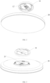
FIG. 1 is a decomposition schematic diagram of a ceiling lamp according to a preferred embodiment of the present application. -
FIG. 2 is a schematic diagram of an electrical connection of a ceiling lamp according to a preferred embodiment of the present application. -
FIG. 3 is a schematic diagram from another perspective of an electrical connection of a ceiling lamp according to a preferred embodiment of the present application. -
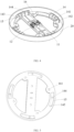
FIG. 4 is a schematic diagram of a quick structure of a ceiling lamp according to a preferred embodiment of the present application. -
FIG. 5 is a schematic diagram from another perspective of a quick structure of a ceiling lamp according to a preferred embodiment of the present application. -
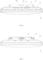
FIG. 6 is a cross-sectional schematic diagram of a ceiling lamp according to a preferred embodiment of the present application. -
FIG. 7 is a cross-sectional schematic diagram from another perspective of a ceiling lamp according to a preferred embodiment of the present application. - In order to make the purpose, technical solutions, and advantages of the present application clearer, a detailed description of the present application will be provided below in conjunction with the accompanying drawings and specific embodiments.
- It should be noted that in order to avoid blurring the present application due to unnecessary details, only the structure and/or processing steps closely related to the object of the present application are shown in the accompanying drawings, and other details that are not closely related to the present application are omitted.
- In addition, it should be noted that the terms "comprise", "comprising", "include", "including", or any other variant are intended to encompass non exclusive inclusion, such that a process, a method, an item, or a device that includes a series of elements not only includes those elements, but also other elements that are not explicitly listed, or also include elements inherent to such a process, a method, an item, or a device.
- As shown in
FIG. 1 to FIG. 7 , the present application discloses aceiling lamp 100, theceiling lamp 100 is provided with aquick connection structure 10 for mounting on a mounting surface. Thequick connection structure 10 can connect different lamps to meet the different requirements of users, and there is no limitation here. For clarity, the following section of the specification will provide a detailed illustration of the specific structure of theceiling lamp 100. - As shown in
FIG. 1 , theceiling lamp 100 includes aquick connection structure 10 and alamp body 20. Thequick connection structure 10 is in a circular shape, and one side of thequick connection structure 10 is fixed on a mounting surface, the other side of thequick connection structure 10 is configured to install thelamp body 20. Thequick connection structure 10 is provided with aconnector 11 that is radially arranged, theconnector 11 is configured to be connected with an inner side of thequick connection structure 10 to enhance the strength of thequick connection structure 10, and a gap is reserved on two sides of theconnector 11 for thelamp body 20 to dissipate heat. The width of theconnector 11 can be set as needed, which is not limited herein. - The
connector 11 is provided with awiring terminal 12, thewiring terminal 12 has a first end facing the mounting surface and a second end facing thelamp body 20. The first end and the second end are electrically conductive, and the first end of thewiring terminal 12 is configured to be connected with a wire of the mounting surface, and the second end of thewiring terminal 12 is configured to be connected with a wire of aconnection port 21 of the lamp body 20 (not shown). It can be understood that the second end of thewiring terminal 12 can be detachably connected to theconnection port 21 of thelamp body 20 for easy installation and disassembly. The second end of thewiring terminal 12 includes but is not limited to a press type structure or a locking type structure. It can be understood that during the installation process of theceiling lamp 100, only thequick connection structure 10 needs to be preinstalled and the wire of the installation surface needs to be connected to quickly install thelamp body 20. - As shown in
FIG. 2 and FIG. 3 , in another preferred embodiment of the present application, the wiring terminal 12' and the connection port 21' can also be electrically connected using the structure of an electrical connector. In this way, there is no need to set a wire between the wiring terminal 12' and the connection port 21', which is not limited herein, as long as it is easy to install and disassemble. - Specifically, an edge of the
quick connection structure 10 is formed with a firstannular wall 13 extending towards thelamp body 20, and thelamp body 20 is provided with a secondannular wall 22 extending towards thequick connection structure 10. The firstannular wall 13 is opposite to the secondannular wall 22, and the secondannular wall 22 is located on an inner side of the firstannular wall 13, that is, thequick connection structure 10 covers an outer side of the secondannular wall 22. - In another embodiment of the present application, the first
annular wall 13 and the secondannular wall 22 can be tightly combined to prevent loosening, which can be set as needed, which is not limited herein. In other embodiments of the present application, there may be a mutually matched threaded structure between the firstannular wall 13 and the secondannular wall 22 to enable thelamp body 20 to be securely connected to thequick connection structure 10 through rotation, which is not limited herein. - As shown in
FIG. 6 and FIG. 7 , preferably, thelamp body 20 includes alampshell 24 and alampshade 25, thelamp lampshell 24 is sealed and assembled with thelampshade 25, so that thelamp body 20 can achieve integrated sealing, and therefore users only need to assemble thelamp body 20 with thequick connection structure 10. - As shown in
FIG. 4 , further, thequick connection structure 10 is provided with a first limitingmember 14, the first limitingmember 14 includes abearing portion 141 and astop portion 142, and thebearing portion 141 and thestop portion 142 are enclosed to form anaccommodating chamber 143, theaccommodating chamber 143 is provided with an opening that is horizontally oriented, the opening and thestop portion 142 are respectively located on both sides of thebearing portion 141. The inner wall of the secondannular wall 22 is provided with a second limitingmember 23 for cooperating with the first limitingmember 14. The second limitingmember 23 includes but is not limited to a block shape or a strip shape, and the second limitingmember 23 can enter theaccommodating chamber 143 from the opening to be accommodated in theaccommodating chamber 143. Thebearing portion 141 is configured to carry the second limitingmember 23, that is, carry the weight of thelamp body 20, and thestop portion 142 is configured to prevent the second limitingmember 23 from excessive rotation. In a case that thequick connection structure 10 covers the outer side of the secondannular wall 22, the first limitingmember 14 and the second limitingmember 23 are driven to cooperate with each other by rotating thelamp body 20, to install thelamp body 20 on thequick connection structure 10. In other embodiments of the present application, reinforcing ribs may be provided on the side edges of thebearing portion 141 and thestop portion 142, or thebearing portion 141 and thestop portion 142 may be integrally formed or embedded in thequick connection structure 10, which is not limited herein. - As a preferred embodiment of the present application, the
bearing portion 141 is not horizontally arranged, that is, thebearing portion 141 is higher at the opening and lower at thestop portion 142, in this way, the second limitingmember 23 has a tendency to move towards thestop portion 142 in theaccommodating chamber 143 under the action of gravity, to prevent accidental detachment of thelamp body 20. - As shown in
FIG. 4 and FIG. 5 , specifically, anannular groove 15 is formed between the firstannular wall 13 and the first limitingmember 14 for the rotation of the secondannular wall 22. As the second limitingmember 23 is connected to the inner wall of the secondannular wall 22, a corresponding sliding groove (not shown) for the sliding of the second limitingmember 23 can be opened on the side of theaccommodating chamber 143 facing the firstannular wall 13, and the sliding groove is connected to the opening. - The
annular groove 15 extends towards a radial direction of thequick connection structure 10 to form aninstallation portion 16, theinstallation portion 16 is provided with aninstallation hole 161 and an installation member (not shown). The installation member passes through theinstallation hole 161 to install thequick connection structure 10 on the mounting surface. Theinstallation hole 161 and the installation member include but are not limited to a bolt and a screw hole, and theinstallation portion 16 is arranged close to thestop portion 142. - In a preferred embodiment of the present application, at least two first limiting
members 14 are provided, preferably, four first limitingmembers 14 are provided, and the four first limitingmembers 14 are uniformly distributed on thequick connection structure 10. Correspondingly, four second limitingmembers 23 and fourinstallation portions 16 are provided, thereby enhancing the bearing capacity of the bearingportion 141 on thelamp body 20 and enhancing the stability of the structure. It can be understood that the larger the contact area between the first limitingmember 14 and the second limitingmember 23, the more stable the connection between thelamp body 20 and thequick connection structure 10. Specific arrangements can be made as needed, which is not limited herein. - As shown in
FIG. 5 , in a preferred embodiment of the present application, the second limitingmember 23 is provided with astop rib 231 that is protruding, and astop groove 144 is correspondingly provided in theaccommodating chamber 143 to accommodate thestop rib 231. In a case that the second limitingmember 23 enters theaccommodating chamber 143 from the opening, thestop rib 231 slides into thestop groove 144 to fix the relative position of thelamp body 20 relative to thequick connection structure 10. Specifically, thestop rib 231 may be provided at the lower end of the second limitingmember 23, and thestop groove 144 may be provided on the bearingportion 141. In other embodiments of the present application, thestop rib 231 and thestop groove 144 may also be provided on the side or above of the second limitingmember 23. Of course, it can be understood that thestop groove 144 may be provided on the second limitingmember 23, and thestop rib 231 may be provided in theaccommodating chamber 143. The specific connection structure between the second limitingmember 23 and theaccommodating chamber 143 includes but is not limited to an elastic structure, as long as it is easy to install and disassemble, which is not limited herein. - Preferably, a guiding
inclined surface 145 is provided on the second limitingmember 23, the guidinginclined surface 145 is oriented towards the opening to insert the second limitingmember 23 into theaccommodating chamber 143 from the opening. In this case, the guidinginclined surface 145 can be used to indicate the correct installation direction and prevent incorrect installation. - The
quick connection structure 10 is provided with a throughhole 17 that communicates with theaccommodating chamber 143. The throughhole 17 can be used for heat dissipation of thelamp body 20, while reducing the frictional force between the upper end of the second limitingmember 23 and the corresponding position of the lower end of thequick connection structure 10. - In summary, the
quick connection structure 10 provided by the present application can provide an installation platform for different lamps, which is convenient for installation and disassembly. At the same time, thelamp body 20 is an integrated sealed assembly to avoid the invasion of mosquitoes and dust. - The above embodiments are only used to illustrate the technical solutions of the present application and not to limit the present application. Although the present application has been described in detail with reference to preferred embodiments, ordinary technical personnel in the art should understand that modifications or equivalent replacements can be made to the technical solutions of the present application without departing from the spirit and scope of the technical solutions of the present application.
Claims (13)
- A ceiling lamp, comprising a quick connection structure and a lamp body, wherein the quick connection structure is configured to connect the lamp body to a mounting surface, the quick connection structure is in a circular shape, and an edge of the quick connection structure is formed with a first annular wall extending towards the lamp body, the lamp body is provided with a second annular wall extending towards the quick connection structure, and the second annular wall is provided on an inner side of the first annular wall, the quick connection structure is provided with a first limiting member, an inner wall of the second annular wall is provided with a second limiting member for cooperating with the first limiting member, in a case that the quick connection structure covers an outer side of the second annular wall, the lamp body is rotated to drive the first limiting member to cooperate with the second limiting member to install the lamp body on the quick connection structure.
- The ceiling lamp according to claim 1, wherein an annular groove is provided between the first annular wall and the first limiting member for rotation of the second annular wall, the first limiting member comprises a bearing portion for carrying the second limiting member and a stop portion for preventing excessive rotation of the second limiting member, the bearing portion and the stop portion are enclosed to form an accommodating chamber for accommodating the second limiting member.
- The ceiling lamp according to claim 2, wherein the second limiting member is provided with a stop rib that is protruding, and a stop groove is correspondingly provided in the accommodating chamber for accommodating the stop rib.
- The ceiling lamp according to claim 2, wherein the second limiting element is provided with a guiding inclined surface to facilitate inserting the second limiting element into the accommodating chamber.
- The ceiling lamp according to claim 2, wherein the bearing portion is not horizontally arranged to enable the second limiting member to have a tendency to move towards the stop portion in the accommodating chamber.
- The ceiling lamp according to claim 2, wherein the quick connection structure is provided with a through hole for communicating with the accommodating chamber.
- The ceiling lamp according to claim 2, wherein the annular groove extends towards a radial direction of the quick connection structure to form an installation portion, the installation portion is provided with a mounting hole and a mounting member, the mounting member passes through the mounting hole to install the quick connection structure on the mounting surface.
- The ceiling lamp according to claim 7, wherein at least two first limiting members are provided, and the installation portion is provided close to the stop portion.
- The ceiling lamp according to claim 1, wherein the quick connection structure is provided with a connector that is radially arranged, the connector is configured to be connected with the inner side of the first annular wall, the connector is provided with a wiring terminal, one end of the wiring terminal is configured to be connected with a wire of the mounting surface, and the other end of the wiring terminal is configured to be electrically connected with the lamp body.
- The ceiling lamp according to claim 2, wherein the lamp body comprises a lampshell and a lampshade, and the lampshell is sealed and assembled with the lampshade.
- A quick connection structure, configured to connect a lamp body to a mounting surface, the lamp body being provided with a second limiting member, wherein the quick connection structure is in a circular shape, an edge of the quick connection structure is formed with a first annular wall extending towards the lamp body, the quick connection structure is provided with a first limiting member, and the lamp body is rotated to drive the first limiting member to cooperate with the second limiting member to install the lamp body on the quick connection structure.
- The quick connection structure according to claim 11, wherein an annular groove is provided between the first annular wall and the first limiting member, the first limiting member comprises a bearing portion for carrying the second limiting member and a stop portion for preventing excessive rotation of the second limiting member, the bearing portion and the stop portion are enclosed to form an accommodating chamber for accommodating the second limiting member.
- The quick connection structure according to claim 11, wherein the quick connection structure is provided with a connector that is radially arranged, the connector is configured to be connected with the inner side of the first annular wall, the connector is provided with a wiring terminal, one end of the wiring terminal is configured to be connected with a wire of the mounting surface, and the other end of the wiring terminal is configured to be electrically connected with the lamp body.
Applications Claiming Priority (3)
| Application Number | Priority Date | Filing Date | Title |
|---|---|---|---|
| CN202122369500.0U CN216079536U (en) | 2021-09-29 | 2021-09-29 | Quick-connection structure and ceiling lamp |
| CN202111147423.2A CN113775984A (en) | 2021-09-29 | 2021-09-29 | Quick-connection structure and ceiling lamp |
| PCT/CN2022/112939 WO2023051069A1 (en) | 2021-09-29 | 2022-08-17 | Quick connection structure and ceiling lamp |
Publications (2)
| Publication Number | Publication Date |
|---|---|
| EP4394239A1 true EP4394239A1 (en) | 2024-07-03 |
| EP4394239A4 EP4394239A4 (en) | 2025-01-22 |
Family
ID=85781268
Family Applications (1)
| Application Number | Title | Priority Date | Filing Date |
|---|---|---|---|
| EP22874464.5A Pending EP4394239A4 (en) | 2021-09-29 | 2022-08-17 | QUICK LINK STRUCTURE AND CEILING LAMP |
Country Status (3)
| Country | Link |
|---|---|
| US (1) | US20240295309A1 (en) |
| EP (1) | EP4394239A4 (en) |
| WO (1) | WO2023051069A1 (en) |
Families Citing this family (3)
| Publication number | Priority date | Publication date | Assignee | Title |
|---|---|---|---|---|
| USD1058025S1 (en) * | 2022-03-25 | 2025-01-14 | shenzhen Homi Lighting Co., ltd | LED ceiling lamp |
| USD1070151S1 (en) * | 2022-03-25 | 2025-04-08 | shenzhen Homi Lighting Co., ltd | LED panel light |
| USD1117906S1 (en) * | 2023-05-24 | 2026-03-10 | Jinmei LI | Lens for a ceiling light |
Family Cites Families (9)
| Publication number | Priority date | Publication date | Assignee | Title |
|---|---|---|---|---|
| JP6152940B2 (en) * | 2013-10-11 | 2017-06-28 | パナソニックIpマネジメント株式会社 | Lighting fixture adapter and lighting fixture |
| CN207599436U (en) * | 2017-09-05 | 2018-07-10 | 青岛亿联客信息技术有限公司 | For assisting the device and its ceiling lamp of installation ceiling lamp |
| CN207527424U (en) * | 2017-11-21 | 2018-06-22 | 厦门恩耐照明技术有限公司 | A kind of lamp design of ceiling lamp |
| CN209726005U (en) * | 2019-05-24 | 2019-12-03 | 中山市凯迪佳电子有限公司 | A kind of split type ceiling lamp and its power pack facilitating installation |
| CN110056807A (en) * | 2019-05-24 | 2019-07-26 | 中山市凯迪佳电子有限公司 | A kind of split type ceiling lamp facilitating installation and its application method |
| CN213394941U (en) * | 2020-10-12 | 2021-06-08 | 深圳市豪恩智能物联股份有限公司 | Installation structure and ceiling light |
| DE202021000169U1 (en) * | 2021-01-11 | 2021-04-20 | Guangdong Lijing lntelligent Lighting Co., Ltd | An ultra-thin panel lamp mounting structure |
| CN113124353A (en) * | 2021-05-25 | 2021-07-16 | 欧普照明电器(中山)有限公司 | Ceiling lamp |
| CN113775984A (en) * | 2021-09-29 | 2021-12-10 | 苏州欧普照明有限公司 | Quick-connection structure and ceiling lamp |
-
2022
- 2022-08-17 EP EP22874464.5A patent/EP4394239A4/en active Pending
- 2022-08-17 WO PCT/CN2022/112939 patent/WO2023051069A1/en not_active Ceased
-
2024
- 2024-03-06 US US18/596,768 patent/US20240295309A1/en active Pending
Also Published As
| Publication number | Publication date |
|---|---|
| EP4394239A4 (en) | 2025-01-22 |
| US20240295309A1 (en) | 2024-09-05 |
| WO2023051069A1 (en) | 2023-04-06 |
Similar Documents
| Publication | Publication Date | Title |
|---|---|---|
| US20240295309A1 (en) | Quick connection structure and ceiling lamp | |
| CN113775984A (en) | Quick-connection structure and ceiling lamp | |
| CN112803210A (en) | Connector and lamp assembly | |
| CN216079536U (en) | Quick-connection structure and ceiling lamp | |
| CN217109322U (en) | Lamp fixing device and ceiling lamp | |
| CN211902542U (en) | LED three-proofing lamp | |
| CN209569695U (en) | Luminaires and luminaire components | |
| CN220911292U (en) | LED explosion-proof lamp | |
| CN104349562B (en) | The box body of ballast structure of lamps and lanterns | |
| CN215908961U (en) | Dustproof flame-proof miner's lamp | |
| CN110131685B (en) | Lamp shell and lamp mounting structure | |
| CN213394809U (en) | Casual spotlight | |
| CN108832370A (en) | an adapter | |
| WO2022247662A1 (en) | Ceiling lamp | |
| CN210317871U (en) | Special copper sleeve of split type radiator fan | |
| CN209762963U (en) | Lamp adjusting structure and lamp | |
| CN114321783A (en) | Lamp shell assembly and lamp applying same | |
| CN217608131U (en) | Improved industrial case | |
| CN223448331U (en) | A lamp that is easy to install | |
| CN212408424U (en) | Clean lamp and lamp | |
| CN223360577U (en) | Plug and play drive power supply | |
| CN223178782U (en) | Dampproofing lamp convenient to wiring | |
| CN207652810U (en) | Electric control box | |
| CN219654955U (en) | Mounting structure for small fan blade | |
| CN213457614U (en) | A rotatory lamp strip of light filling for film studio |
Legal Events
| Date | Code | Title | Description |
|---|---|---|---|
| STAA | Information on the status of an ep patent application or granted ep patent |
Free format text: STATUS: THE INTERNATIONAL PUBLICATION HAS BEEN MADE |
|
| PUAI | Public reference made under article 153(3) epc to a published international application that has entered the european phase |
Free format text: ORIGINAL CODE: 0009012 |
|
| STAA | Information on the status of an ep patent application or granted ep patent |
Free format text: STATUS: REQUEST FOR EXAMINATION WAS MADE |
|
| 17P | Request for examination filed |
Effective date: 20240328 |
|
| AK | Designated contracting states |
Kind code of ref document: A1 Designated state(s): AL AT BE BG CH CY CZ DE DK EE ES FI FR GB GR HR HU IE IS IT LI LT LU LV MC MK MT NL NO PL PT RO RS SE SI SK SM TR |
|
| DAV | Request for validation of the european patent (deleted) | ||
| DAX | Request for extension of the european patent (deleted) | ||
| A4 | Supplementary search report drawn up and despatched |
Effective date: 20241219 |
|
| RIC1 | Information provided on ipc code assigned before grant |
Ipc: F21Y 115/10 20160101ALN20241213BHEP Ipc: F21V 31/00 20060101ALN20241213BHEP Ipc: F21V 23/06 20060101ALI20241213BHEP Ipc: F21V 21/03 20060101ALI20241213BHEP Ipc: F21V 17/14 20060101ALI20241213BHEP Ipc: F21S 8/04 20060101AFI20241213BHEP |