EP4394236A1 - A storage tank for a vehicle for storing fluids - Google Patents
A storage tank for a vehicle for storing fluids Download PDFInfo
- Publication number
- EP4394236A1 EP4394236A1 EP23150004.2A EP23150004A EP4394236A1 EP 4394236 A1 EP4394236 A1 EP 4394236A1 EP 23150004 A EP23150004 A EP 23150004A EP 4394236 A1 EP4394236 A1 EP 4394236A1
- Authority
- EP
- European Patent Office
- Prior art keywords
- wall
- storage tank
- wall member
- plate wall
- conical plate
- Prior art date
- Legal status (The legal status is an assumption and is not a legal conclusion. Google has not performed a legal analysis and makes no representation as to the accuracy of the status listed.)
- Granted
Links
Images


Classifications
-
- F—MECHANICAL ENGINEERING; LIGHTING; HEATING; WEAPONS; BLASTING
- F17—STORING OR DISTRIBUTING GASES OR LIQUIDS
- F17C—VESSELS FOR CONTAINING OR STORING COMPRESSED, LIQUEFIED OR SOLIDIFIED GASES; FIXED-CAPACITY GAS-HOLDERS; FILLING VESSELS WITH, OR DISCHARGING FROM VESSELS, COMPRESSED, LIQUEFIED, OR SOLIDIFIED GASES
- F17C13/00—Details of vessels or of the filling or discharging of vessels
-
- B—PERFORMING OPERATIONS; TRANSPORTING
- B60—VEHICLES IN GENERAL
- B60K—ARRANGEMENT OR MOUNTING OF PROPULSION UNITS OR OF TRANSMISSIONS IN VEHICLES; ARRANGEMENT OR MOUNTING OF PLURAL DIVERSE PRIME-MOVERS IN VEHICLES; AUXILIARY DRIVES FOR VEHICLES; INSTRUMENTATION OR DASHBOARDS FOR VEHICLES; ARRANGEMENTS IN CONNECTION WITH COOLING, AIR INTAKE, GAS EXHAUST OR FUEL SUPPLY OF PROPULSION UNITS IN VEHICLES
- B60K15/00—Arrangement in connection with fuel supply of combustion engines or other fuel consuming energy converters, e.g. fuel cells; Mounting or construction of fuel tanks
- B60K15/03—Fuel tanks
- B60K15/077—Fuel tanks with means modifying or controlling distribution or motion of fuel, e.g. to prevent noise, surge, splash or fuel starvation
-
- F—MECHANICAL ENGINEERING; LIGHTING; HEATING; WEAPONS; BLASTING
- F17—STORING OR DISTRIBUTING GASES OR LIQUIDS
- F17C—VESSELS FOR CONTAINING OR STORING COMPRESSED, LIQUEFIED OR SOLIDIFIED GASES; FIXED-CAPACITY GAS-HOLDERS; FILLING VESSELS WITH, OR DISCHARGING FROM VESSELS, COMPRESSED, LIQUEFIED, OR SOLIDIFIED GASES
- F17C13/00—Details of vessels or of the filling or discharging of vessels
- F17C13/08—Mounting arrangements for vessels
- F17C13/084—Mounting arrangements for vessels for small-sized storage vessels, e.g. compressed gas cylinders or bottles, disposable gas vessels, vessels adapted for automotive use
-
- B—PERFORMING OPERATIONS; TRANSPORTING
- B60—VEHICLES IN GENERAL
- B60K—ARRANGEMENT OR MOUNTING OF PROPULSION UNITS OR OF TRANSMISSIONS IN VEHICLES; ARRANGEMENT OR MOUNTING OF PLURAL DIVERSE PRIME-MOVERS IN VEHICLES; AUXILIARY DRIVES FOR VEHICLES; INSTRUMENTATION OR DASHBOARDS FOR VEHICLES; ARRANGEMENTS IN CONNECTION WITH COOLING, AIR INTAKE, GAS EXHAUST OR FUEL SUPPLY OF PROPULSION UNITS IN VEHICLES
- B60K15/00—Arrangement in connection with fuel supply of combustion engines or other fuel consuming energy converters, e.g. fuel cells; Mounting or construction of fuel tanks
- B60K15/03—Fuel tanks
- B60K15/077—Fuel tanks with means modifying or controlling distribution or motion of fuel, e.g. to prevent noise, surge, splash or fuel starvation
- B60K2015/0777—Fuel tanks with means modifying or controlling distribution or motion of fuel, e.g. to prevent noise, surge, splash or fuel starvation in-tank reservoirs or baffles integrally manufactured with the fuel Tank
-
- F—MECHANICAL ENGINEERING; LIGHTING; HEATING; WEAPONS; BLASTING
- F17—STORING OR DISTRIBUTING GASES OR LIQUIDS
- F17C—VESSELS FOR CONTAINING OR STORING COMPRESSED, LIQUEFIED OR SOLIDIFIED GASES; FIXED-CAPACITY GAS-HOLDERS; FILLING VESSELS WITH, OR DISCHARGING FROM VESSELS, COMPRESSED, LIQUEFIED, OR SOLIDIFIED GASES
- F17C2201/00—Vessel construction, in particular geometry, arrangement or size
- F17C2201/01—Shape
- F17C2201/0104—Shape cylindrical
- F17C2201/0109—Shape cylindrical with exteriorly curved end-piece
-
- F—MECHANICAL ENGINEERING; LIGHTING; HEATING; WEAPONS; BLASTING
- F17—STORING OR DISTRIBUTING GASES OR LIQUIDS
- F17C—VESSELS FOR CONTAINING OR STORING COMPRESSED, LIQUEFIED OR SOLIDIFIED GASES; FIXED-CAPACITY GAS-HOLDERS; FILLING VESSELS WITH, OR DISCHARGING FROM VESSELS, COMPRESSED, LIQUEFIED, OR SOLIDIFIED GASES
- F17C2201/00—Vessel construction, in particular geometry, arrangement or size
- F17C2201/01—Shape
- F17C2201/0176—Shape variable
-
- F—MECHANICAL ENGINEERING; LIGHTING; HEATING; WEAPONS; BLASTING
- F17—STORING OR DISTRIBUTING GASES OR LIQUIDS
- F17C—VESSELS FOR CONTAINING OR STORING COMPRESSED, LIQUEFIED OR SOLIDIFIED GASES; FIXED-CAPACITY GAS-HOLDERS; FILLING VESSELS WITH, OR DISCHARGING FROM VESSELS, COMPRESSED, LIQUEFIED, OR SOLIDIFIED GASES
- F17C2201/00—Vessel construction, in particular geometry, arrangement or size
- F17C2201/01—Shape
- F17C2201/0176—Shape variable
- F17C2201/0185—Shape variable with separating membrane
-
- F—MECHANICAL ENGINEERING; LIGHTING; HEATING; WEAPONS; BLASTING
- F17—STORING OR DISTRIBUTING GASES OR LIQUIDS
- F17C—VESSELS FOR CONTAINING OR STORING COMPRESSED, LIQUEFIED OR SOLIDIFIED GASES; FIXED-CAPACITY GAS-HOLDERS; FILLING VESSELS WITH, OR DISCHARGING FROM VESSELS, COMPRESSED, LIQUEFIED, OR SOLIDIFIED GASES
- F17C2201/00—Vessel construction, in particular geometry, arrangement or size
- F17C2201/03—Orientation
- F17C2201/035—Orientation with substantially horizontal main axis
-
- F—MECHANICAL ENGINEERING; LIGHTING; HEATING; WEAPONS; BLASTING
- F17—STORING OR DISTRIBUTING GASES OR LIQUIDS
- F17C—VESSELS FOR CONTAINING OR STORING COMPRESSED, LIQUEFIED OR SOLIDIFIED GASES; FIXED-CAPACITY GAS-HOLDERS; FILLING VESSELS WITH, OR DISCHARGING FROM VESSELS, COMPRESSED, LIQUEFIED, OR SOLIDIFIED GASES
- F17C2201/00—Vessel construction, in particular geometry, arrangement or size
- F17C2201/05—Size
- F17C2201/056—Small (<1 m3)
-
- F—MECHANICAL ENGINEERING; LIGHTING; HEATING; WEAPONS; BLASTING
- F17—STORING OR DISTRIBUTING GASES OR LIQUIDS
- F17C—VESSELS FOR CONTAINING OR STORING COMPRESSED, LIQUEFIED OR SOLIDIFIED GASES; FIXED-CAPACITY GAS-HOLDERS; FILLING VESSELS WITH, OR DISCHARGING FROM VESSELS, COMPRESSED, LIQUEFIED, OR SOLIDIFIED GASES
- F17C2203/00—Vessel construction, in particular walls or details thereof
- F17C2203/06—Materials for walls or layers thereof; Properties or structures of walls or their materials
- F17C2203/0602—Wall structures; Special features thereof
- F17C2203/0612—Wall structures
- F17C2203/0614—Single wall
-
- F—MECHANICAL ENGINEERING; LIGHTING; HEATING; WEAPONS; BLASTING
- F17—STORING OR DISTRIBUTING GASES OR LIQUIDS
- F17C—VESSELS FOR CONTAINING OR STORING COMPRESSED, LIQUEFIED OR SOLIDIFIED GASES; FIXED-CAPACITY GAS-HOLDERS; FILLING VESSELS WITH, OR DISCHARGING FROM VESSELS, COMPRESSED, LIQUEFIED, OR SOLIDIFIED GASES
- F17C2203/00—Vessel construction, in particular walls or details thereof
- F17C2203/06—Materials for walls or layers thereof; Properties or structures of walls or their materials
- F17C2203/0634—Materials for walls or layers thereof
- F17C2203/0636—Metals
-
- F—MECHANICAL ENGINEERING; LIGHTING; HEATING; WEAPONS; BLASTING
- F17—STORING OR DISTRIBUTING GASES OR LIQUIDS
- F17C—VESSELS FOR CONTAINING OR STORING COMPRESSED, LIQUEFIED OR SOLIDIFIED GASES; FIXED-CAPACITY GAS-HOLDERS; FILLING VESSELS WITH, OR DISCHARGING FROM VESSELS, COMPRESSED, LIQUEFIED, OR SOLIDIFIED GASES
- F17C2221/00—Handled fluid, in particular type of fluid
- F17C2221/03—Mixtures
- F17C2221/032—Hydrocarbons
- F17C2221/033—Methane, e.g. natural gas, CNG, LNG, GNL, GNC, PLNG
-
- F—MECHANICAL ENGINEERING; LIGHTING; HEATING; WEAPONS; BLASTING
- F17—STORING OR DISTRIBUTING GASES OR LIQUIDS
- F17C—VESSELS FOR CONTAINING OR STORING COMPRESSED, LIQUEFIED OR SOLIDIFIED GASES; FIXED-CAPACITY GAS-HOLDERS; FILLING VESSELS WITH, OR DISCHARGING FROM VESSELS, COMPRESSED, LIQUEFIED, OR SOLIDIFIED GASES
- F17C2221/00—Handled fluid, in particular type of fluid
- F17C2221/03—Mixtures
- F17C2221/032—Hydrocarbons
- F17C2221/035—Propane butane, e.g. LPG, GPL
-
- F—MECHANICAL ENGINEERING; LIGHTING; HEATING; WEAPONS; BLASTING
- F17—STORING OR DISTRIBUTING GASES OR LIQUIDS
- F17C—VESSELS FOR CONTAINING OR STORING COMPRESSED, LIQUEFIED OR SOLIDIFIED GASES; FIXED-CAPACITY GAS-HOLDERS; FILLING VESSELS WITH, OR DISCHARGING FROM VESSELS, COMPRESSED, LIQUEFIED, OR SOLIDIFIED GASES
- F17C2223/00—Handled fluid before transfer, i.e. state of fluid when stored in the vessel or before transfer from the vessel
- F17C2223/01—Handled fluid before transfer, i.e. state of fluid when stored in the vessel or before transfer from the vessel characterised by the phase
- F17C2223/0146—Two-phase
- F17C2223/0153—Liquefied gas, e.g. LPG, GPL
-
- F—MECHANICAL ENGINEERING; LIGHTING; HEATING; WEAPONS; BLASTING
- F17—STORING OR DISTRIBUTING GASES OR LIQUIDS
- F17C—VESSELS FOR CONTAINING OR STORING COMPRESSED, LIQUEFIED OR SOLIDIFIED GASES; FIXED-CAPACITY GAS-HOLDERS; FILLING VESSELS WITH, OR DISCHARGING FROM VESSELS, COMPRESSED, LIQUEFIED, OR SOLIDIFIED GASES
- F17C2223/00—Handled fluid before transfer, i.e. state of fluid when stored in the vessel or before transfer from the vessel
- F17C2223/01—Handled fluid before transfer, i.e. state of fluid when stored in the vessel or before transfer from the vessel characterised by the phase
- F17C2223/0146—Two-phase
- F17C2223/0153—Liquefied gas, e.g. LPG, GPL
- F17C2223/0161—Liquefied gas, e.g. LPG, GPL cryogenic, e.g. LNG, GNL, PLNG
-
- F—MECHANICAL ENGINEERING; LIGHTING; HEATING; WEAPONS; BLASTING
- F17—STORING OR DISTRIBUTING GASES OR LIQUIDS
- F17C—VESSELS FOR CONTAINING OR STORING COMPRESSED, LIQUEFIED OR SOLIDIFIED GASES; FIXED-CAPACITY GAS-HOLDERS; FILLING VESSELS WITH, OR DISCHARGING FROM VESSELS, COMPRESSED, LIQUEFIED, OR SOLIDIFIED GASES
- F17C2223/00—Handled fluid before transfer, i.e. state of fluid when stored in the vessel or before transfer from the vessel
- F17C2223/03—Handled fluid before transfer, i.e. state of fluid when stored in the vessel or before transfer from the vessel characterised by the pressure level
- F17C2223/033—Small pressure, e.g. for liquefied gas
-
- F—MECHANICAL ENGINEERING; LIGHTING; HEATING; WEAPONS; BLASTING
- F17—STORING OR DISTRIBUTING GASES OR LIQUIDS
- F17C—VESSELS FOR CONTAINING OR STORING COMPRESSED, LIQUEFIED OR SOLIDIFIED GASES; FIXED-CAPACITY GAS-HOLDERS; FILLING VESSELS WITH, OR DISCHARGING FROM VESSELS, COMPRESSED, LIQUEFIED, OR SOLIDIFIED GASES
- F17C2260/00—Purposes of gas storage and gas handling
- F17C2260/01—Improving mechanical properties or manufacturing
- F17C2260/016—Preventing slosh
-
- F—MECHANICAL ENGINEERING; LIGHTING; HEATING; WEAPONS; BLASTING
- F17—STORING OR DISTRIBUTING GASES OR LIQUIDS
- F17C—VESSELS FOR CONTAINING OR STORING COMPRESSED, LIQUEFIED OR SOLIDIFIED GASES; FIXED-CAPACITY GAS-HOLDERS; FILLING VESSELS WITH, OR DISCHARGING FROM VESSELS, COMPRESSED, LIQUEFIED, OR SOLIDIFIED GASES
- F17C2270/00—Applications
- F17C2270/01—Applications for fluid transport or storage
- F17C2270/0165—Applications for fluid transport or storage on the road
- F17C2270/0168—Applications for fluid transport or storage on the road by vehicles
-
- F—MECHANICAL ENGINEERING; LIGHTING; HEATING; WEAPONS; BLASTING
- F17—STORING OR DISTRIBUTING GASES OR LIQUIDS
- F17C—VESSELS FOR CONTAINING OR STORING COMPRESSED, LIQUEFIED OR SOLIDIFIED GASES; FIXED-CAPACITY GAS-HOLDERS; FILLING VESSELS WITH, OR DISCHARGING FROM VESSELS, COMPRESSED, LIQUEFIED, OR SOLIDIFIED GASES
- F17C2270/00—Applications
- F17C2270/01—Applications for fluid transport or storage
- F17C2270/0165—Applications for fluid transport or storage on the road
- F17C2270/0168—Applications for fluid transport or storage on the road by vehicles
- F17C2270/0171—Trucks
-
- F—MECHANICAL ENGINEERING; LIGHTING; HEATING; WEAPONS; BLASTING
- F17—STORING OR DISTRIBUTING GASES OR LIQUIDS
- F17C—VESSELS FOR CONTAINING OR STORING COMPRESSED, LIQUEFIED OR SOLIDIFIED GASES; FIXED-CAPACITY GAS-HOLDERS; FILLING VESSELS WITH, OR DISCHARGING FROM VESSELS, COMPRESSED, LIQUEFIED, OR SOLIDIFIED GASES
- F17C2270/00—Applications
- F17C2270/01—Applications for fluid transport or storage
- F17C2270/0165—Applications for fluid transport or storage on the road
- F17C2270/0168—Applications for fluid transport or storage on the road by vehicles
- F17C2270/0176—Buses
-
- F—MECHANICAL ENGINEERING; LIGHTING; HEATING; WEAPONS; BLASTING
- F17—STORING OR DISTRIBUTING GASES OR LIQUIDS
- F17C—VESSELS FOR CONTAINING OR STORING COMPRESSED, LIQUEFIED OR SOLIDIFIED GASES; FIXED-CAPACITY GAS-HOLDERS; FILLING VESSELS WITH, OR DISCHARGING FROM VESSELS, COMPRESSED, LIQUEFIED, OR SOLIDIFIED GASES
- F17C2270/00—Applications
- F17C2270/01—Applications for fluid transport or storage
- F17C2270/0165—Applications for fluid transport or storage on the road
- F17C2270/0168—Applications for fluid transport or storage on the road by vehicles
- F17C2270/0178—Cars
Definitions
- Storage tanks for storing fluids in vehicles may be designed in different ways depending on the specific needs for the vehicle. For example, it is known to design storage tanks for storing diesel, gasoline, liquid natural gas (LNG), washer fluids, etc.
- LNG liquid natural gas
- the storage tank further comprises a sealing element attached to a radially outer edge of the at least one wall.
- a technical benefit may include an improved sealing function between the inner envelope surface and the at least one wall member, e.g., preventing any unwanted leakage of fluids.
- the sealing element may completely enclose the radially outer edge, i.e. it may enclose a complete perimeter of the at least one wall member.
- the sealing element comprises a fastening portion which protrudes radially inwardly of the at least one wall and is located in-between the second concave-shaped side and the first wall side when the base plate wall member and the conical plate wall member are attached to each other.
- a technical benefit may include an improved connection of the sealing element to the at least one wall, reducing e.g. a risk of detachment of the sealing element when moving the at least one wall inside the storage tank.
- the attachment arrangement is extending through a center point of the at least one wall.
- a technical benefit may include that it provides more uniform attachment forces for keeping the base plate wall member and the conical wall member pressed together. As such, a more reliable and robust attachment may be obtained.
- At least one of the at least one wall is a partition wall dividing the inner volume into at least two sub-volumes.
- a technical benefit may include that it allows sub-volumes of the storage tank to be adjusted.
- the storage tank 1 comprises an inner envelope surface 10 defining an inner volume 12 for storing fluids.
- the storage tank 1 further comprises at least one wall 20, 20', 20", 20′′′ which is releasably attached to the inner envelope surface 10 and defines a fluid barrier for fluid in the inner volume 12.
- the storage tank 1 is configured for storing more than one fluid.
- the storage tank 1 may have any number of such walls, for example one, two, three or more walls which are configured according to any one of the examples of the first aspect of the disclosure.
- FIG. 3 depicts a cross-sectional view of such a wall, in this example the wall 20 shown in FIGS. 2a-b . It shall however be noted that any of the other walls 20', 20", 20′′′ may be configured in a similar manner.
- FIGS. 4 and 5 show enlarged views of the wall 20 in FIG. 3 .
- FIG. 4 is an enlarged view of a center portion of the wall 20 and
- FIG. 5 is an enlarged view of a peripheral portion of the wall 20.
- the storage tank 1 may further comprise a sealing element 26 attached to a radially outer edge 202 of the at least one wall 20, 20', 20", 20'".
- the sealing element 26 may for example be made of rubber or any other suitable polymer, or any combination of different polymers.
- the sealing element 26 may comprise one or more sealing lips 264 which is/are configured to contact the inner envelope surface 10.
- the radially outer edge 246 of the conical plate wall member 24 may comprise a cylindrically shaped outer surface 2462 facing towards the inner envelope surface 10.
- the cylindrically shaped outer surface 2462 extends in the longitudinal direction L, thereby forming an outer peripheral surface 2462 facing the inner envelope surface 10.
- the cylindrically shaped outer surface 2462 may imply improved stability and attachment interface to the inner envelope surface 10, e.g., reducing the risk of twisting of the wall 20 and/or improving sealing.
- the at least one wall 20, 20', 20", 20′′′ may be an outer wall 20, 20′′′ of the storage tank 1. Additionally or alternatively, the at least one wall 20, 20', 20", 20′′′ may be a partition wall 20', 20" dividing the inner volume 12 into at least two sub-volumes 120, 122, 124. In the shown example, there are three sub-volumes 120, 122, 124.
Landscapes
- Engineering & Computer Science (AREA)
- Mechanical Engineering (AREA)
- General Engineering & Computer Science (AREA)
- Life Sciences & Earth Sciences (AREA)
- Sustainable Development (AREA)
- Sustainable Energy (AREA)
- Chemical & Material Sciences (AREA)
- Combustion & Propulsion (AREA)
- Transportation (AREA)
- Cooling, Air Intake And Gas Exhaust, And Fuel Tank Arrangements In Propulsion Units (AREA)
Abstract
- an inner envelope surface (10) defining an inner volume (12) for storing fluids,
- at least one wall (20, 20', 20", 20‴) which is releasably attached to the inner envelope surface (10) and defines a fluid barrier for fluid in the inner volume (12), wherein the inner envelope surface (10) is cylinder-formed and wherein the at least one wall (20, 20', 20", 20‴) is associated with a radial plane of the cylinder-formed inner envelope surface (10),
wherein the at least one wall (20, 20', 20", 20‴) is configured to be moved inside the inner volume (12) to change a volume size of the inner volume (12) and/or to change volume sizes of sub-volumes (120, 122, 124) of the inner volume (12). The disclosure also relates to a vehicle (100).
Description
- The disclosure relates generally to storage tanks for vehicles. In particular aspects, the disclosure relates to a storage tank for a vehicle for storing fluids, and to a vehicle. The disclosure can be applied in heavy-duty vehicles, such as trucks, buses, and construction equipment. Although the disclosure may be described with respect to a particular vehicle, the disclosure is not restricted to any particular vehicle.
- Storage tanks for storing fluids in vehicles may be designed in different ways depending on the specific needs for the vehicle. For example, it is known to design storage tanks for storing diesel, gasoline, liquid natural gas (LNG), washer fluids, etc.
- A storage tank may be designed to store more than one fluid by providing sub-volumes in the storage tank.
- Even though it is known to provide storage tanks for storing more than one fluid, there is still a strive to develop improved technology relating to storage tanks for storing more than one fluid.
- According to a first aspect of the disclosure, there is provided a storage tank for a vehicle for storing fluids, comprising:
- an inner envelope surface defining an inner volume for storing fluids,
- at least one wall which is releasably attached to the inner envelope surface and defines a fluid barrier for fluid in the inner volume, wherein the inner envelope surface is cylinder-formed and wherein the at least one wall is associated with a radial plane of the cylinder-formed inner envelope surface,
- wherein the at least one wall is configured to be moved inside the inner volume to change a volume size of the inner volume and/or to change volume sizes of sub-volumes of the inner volume,
- wherein the at least one wall comprises a base plate wall member and a conical plate wall member which are attached to each other, the conical plate wall member having a first convex-shaped side and a second concave-shaped side,
- wherein the second concave-shaped side is facing a first wall side of the base plate wall member when the base plate wall member and the conical plate wall member are attached to each other,
- wherein the at least one wall is configured to be attached to the inner envelope surface by pressing the conical plate wall member towards the base plate wall member so that the conical plate wall member is expanded in a radial direction thereof. The first aspect of the disclosure may seek to provide a flexible storage tank for fluids in which more than one fluid can be stored in a reliable manner. A technical benefit may include that the at least one wall may be easily moved in the inner volume whilst still enabling a secure and robust attachment to the inner envelope surface in a leak-free manner. By the provision of the first aspect of the disclosure, for example by the configuration of the base plate wall member and the conical plate wall member which are attached to each other, a robust and secure attachment to the inner envelope surface can be achieved. This is achieved in that the conical plate wall member is pressed towards the base plate wall member, thereby enabling the radial expansion of the conical plate wall member. It has been found that this configuration provides a reliable and robust attachment, whilst still enabling for easy adjustment of the wall member in the storage tank.
- In some examples, the at least one wall is configured to be released from the inner envelope surface by moving the conical plate wall member in a direction away from the base plate wall member so that an extension of the conical plate wall member in the radial direction is reduced. A technical benefit may include that the at least one wall can thereby be easily released from the inner envelope surface so that it allows the at least one wall member to be moved inside the inner volume.
- In some examples, the storage tank further comprises a sealing element attached to a radially outer edge of the at least one wall. A technical benefit may include an improved sealing function between the inner envelope surface and the at least one wall member, e.g., preventing any unwanted leakage of fluids. The sealing element may completely enclose the radially outer edge, i.e. it may enclose a complete perimeter of the at least one wall member.
- In some examples, the sealing element is attached to a radially outer edge of the conical plate wall member and/or a radially outer edge of the base plate wall member. The sealing element may completely enclose the radially outer edge of the conical plate wall member and/or the radially outer edge of the base plate wall member.
- In some examples, the sealing element comprises a fastening portion which protrudes radially inwardly of the at least one wall and is located in-between the second concave-shaped side and the first wall side when the base plate wall member and the conical plate wall member are attached to each other. A technical benefit may include an improved connection of the sealing element to the at least one wall, reducing e.g. a risk of detachment of the sealing element when moving the at least one wall inside the storage tank.
- In some examples, a radially outer edge of the conical plate wall member comprises a cylindrically shaped outer surface facing towards the inner envelope surface. A technical benefit may include a more reliable attachment to the inner envelope surface, e.g., preventing the at least one wall from twisting when it is moved inside the storage tank.
- In some examples, the at least one wall further comprises an attachment arrangement for pressing the conical plate wall member towards the base plate wall member.
- In some examples, the attachment arrangement comprises at least one of a stud member, a screw member, a nut member, a spring member, such as a compression spring and/or a tension spring.
- In some examples, the attachment arrangement is extending through a center point of the at least one wall. A technical benefit may include that it provides more uniform attachment forces for keeping the base plate wall member and the conical wall member pressed together. As such, a more reliable and robust attachment may be obtained.
- In some examples, at least one of the at least one wall is an outer wall of the storage tank. A technical benefit may include that it allows the total storage volume of the storage tank to be adjusted.
- In some examples, at least one of the at least one wall is a partition wall dividing the inner volume into at least two sub-volumes. A technical benefit may include that it allows sub-volumes of the storage tank to be adjusted.
- In some examples, the at least one wall comprises at least one cover for covering a side of the at least one wall, such as one cover on each side of the at least one wall. A technical benefit may include that it prevents the base plate wall member and/or the conical plate wall member from coming into direct contact with any storage fluid. Thereby, the risk of contaminating any storage fluid and/or for damaging the wall members due to unwanted contact with storage fluid may be reduced.
- According to a second aspect of the disclosure, there is provided a vehicle comprising a storage tank according to any one of the examples of the first aspect of the disclosure. Advantages and effects of examples of the second aspect of the disclosure are analogous to advantages and effects of the first aspect of the disclosure, and vice versa. It shall also be noted that all examples of the first aspect of the disclosure are applicable to and combinable with all examples of the second aspect of the disclosure, and vice versa.
- The above aspects, accompanying claims, and/or examples disclosed herein above and later below may be suitably combined with each other as would be apparent to anyone of ordinary skill in the art.
- Additional features and advantages are disclosed in the following description, claims, and drawings, and in part will be readily apparent therefrom to those skilled in the art or recognized by practicing the disclosure as described herein. There are also disclosed herein control units, computer readable media, and computer program products associated with the above discussed technical benefits.
- With reference to the appended drawings, below follows a more detailed description of aspects of the disclosure cited as examples.
-
FIG. 1 is a side view of a vehicle according to one example. -
FIG. 2a is a cross-sectional and perspective view of a storage tank according one example. -
FIG. 2b is a schematic cross-sectional view of a storage tank according to one example. -
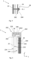
FIG. 3 is a cross-sectional view of a wall according to one example. -
FIG. 4 is an enlarged view of a portion of the example shown inFIG. 3 . -
FIG. 5 is a further enlarged view of another portion of the example shown inFIG. 3 . - The drawings show diagrammatic exemplifying examples of the present disclosure and are thus not necessarily drawn to scale. It shall be understood that the examples shown and described are exemplifying and that the invention is not limited to these examples. It shall also be noted that some details in the drawings may be exaggerated in order to better describe and illustrate the disclosure. Like reference characters refer to like elements throughout the description, unless expressed otherwise.
- Aspects set forth below represent the necessary information to enable those skilled in the art to practice the disclosure.
- An aim of the present disclosure is to provide a flexible storage tank for fluids which alleviates at least one drawback of the prior art, or which at least provides a suitable alternative. For example, by the provision of the present disclosure, a flexible storage tank for fluids is obtained in which the at least one wall is allowed to be attached to the inner envelope surface in a reliable, robust and facilitated manner. Furthermore, by the provision of the present disclosure, the at least one wall is allowed to be moved inside the inner volume in a reliable and facilitated manner. Still further, the configuration of the storage tank may provide a flexible storage tank in a cost-effective manner.
-
FIG. 1 is a side view of avehicle 100 according to one example. Theexample vehicle 100 is herein a truck, more particularly a towing truck for towing one or more trailers (not shown). Even though atruck 100 is shown, in this case a heavy-duty truck, it shall be noted that the present disclosure is not only applicable to trucks, but also to other vehicles, such as buses, construction equipment and passenger cars. The vehicle may also for example be in the form of a vessel, such as a marine vessel. Construction equipment for example comprises dump trucks, wheel loaders, excavators etc. - The
vehicle 100 comprises astorage tank 1 for storing fluids. Thestorage tank 1 may be configured for storing a fuel, such as diesel, gasoline, LNG and hydrogen. The fuel may for example be used by any one of a combustion engine (not shown) and a fuel cell (not shown) for propelling thevehicle 100. Thestorage tank 1 may additionally or alternatively be used for storing other fluids, such as fluids for an exhaust aftertreatment system (EATS) and washer fluids. - With reference to e.g.
FIGS. 2-3 , an example of astorage tank 1 for storing fluids will be described. Thestorage tank 1 may for example be thestorage tank 1 as shown inFIG. 1 . InFIG. 2a , thestorage tank 1 is shown in perspective and cross-sectional view. InFIG. 2b , thestorage tank 1 is shown in schematic and cross-sectional view. The cross-sections correspond to a plane which is defined by a center axis A of thestorage tank 1 which extends in a longitudinal direction L of thestorage tank 1 and by a radial direction r of thestorage tank 1 which orthogonally intersects the center axis A. - The
storage tank 1 comprises aninner envelope surface 10 defining aninner volume 12 for storing fluids. Thestorage tank 1 further comprises at least onewall inner envelope surface 10 and defines a fluid barrier for fluid in theinner volume 12. In the shown example, there are fourwalls storage tank 1 is configured for storing more than one fluid. It shall however be noted that thestorage tank 1 may have any number of such walls, for example one, two, three or more walls which are configured according to any one of the examples of the first aspect of the disclosure.FIG. 3 depicts a cross-sectional view of such a wall, in this example thewall 20 shown inFIGS. 2a-b . It shall however be noted that any of theother walls 20', 20", 20‴ may be configured in a similar manner. - The
inner envelope surface 10 is cylinder-formed and the at least onewall inner envelope surface 10. The cylinder-formedinner envelope surface 10 may for example be a circular cylinder-form, but any other cylinder-form is also applicable, such as with a base which is more squareformed or oval-formed. - The at least one
wall inner volume 12 to change a volume size of theinner volume 12 and/or to change volume sizes ofsub-volumes inner volume 12. The sub-volumes 120, 122, 124 may be used for storing fluids of different kinds. As such, each sub-volume 120, 122, 124 may be associated with a respective opening (not shown) for allowing fluid to be inserted therein and/or to be taken out therefrom. - As may be gleaned from e.g.
FIG. 2a andFIG. 3 , the at least onewall plate wall member 22 and a conicalplate wall member 24 which are attached to each other. The conicalplate wall member 24 has a first convex-shapedside 242 and a second concave-shapedside 244. - The second concave-shaped
side 244 is facing afirst wall side 222 of the baseplate wall member 22 when the baseplate wall member 22 and the conicalplate wall member 24 are attached to each other. The at least onewall inner envelope surface 10 by pressing the conicalplate wall member 24 towards the baseplate wall member 22 so that the conicalplate wall member 24 is expanded in a radial direction r thereof. Accordingly, by way of example, by pressing the conicalplate wall member 24 towards the baseplate wall member 22, a diameter of the conicalplate wall member 24 may be increased, thereby providing an attachment force between the at least onewall inner envelope surface 10. - The at least one
wall inner envelope surface 10 by moving the conicalplate wall member 24 in a direction away from the baseplate wall member 22 so that an extension of the conicalplate wall member 24 in the radial direction r is reduced. -
FIGS. 4 and 5 show enlarged views of thewall 20 inFIG. 3 .FIG. 4 is an enlarged view of a center portion of thewall 20 andFIG. 5 is an enlarged view of a peripheral portion of thewall 20. - With reference to e.g.
FIGS. 3 and5 , it may be gleaned that thestorage tank 1 may further comprise a sealingelement 26 attached to a radiallyouter edge 202 of the at least onewall element 26 may for example be made of rubber or any other suitable polymer, or any combination of different polymers. As shown, the sealingelement 26 may comprise one ormore sealing lips 264 which is/are configured to contact theinner envelope surface 10. - As shown in
FIG. 5 , the sealingelement 26 may be attached to a radiallyouter edge 246 of the conicalplate wall member 24 and/or a radiallyouter edge 226 of the baseplate wall member 22. In the shown example, the sealingelement 26 is attached to the radiallyouter edge 246 of the conicalplate wall member 24 and to the radiallyouter edge 226 of the baseplate wall member 22. - As further shown, the sealing
element 26 may comprise afastening portion 262 which protrudes radially inwardly of the at least onewall side 244 and thefirst wall side 222 when the baseplate wall member 22 and the conicalplate wall member 24 are attached to each other. Thereby, a more robust attachment to thewall 20 may be provided, e.g., preventing the sealingelement 26 from being released from thewall 20. - As shown in
FIG. 5 , the radiallyouter edge 246 of the conicalplate wall member 24 may comprise a cylindrically shapedouter surface 2462 facing towards theinner envelope surface 10. The cylindrically shapedouter surface 2462 extends in the longitudinal direction L, thereby forming an outerperipheral surface 2462 facing theinner envelope surface 10. The cylindrically shapedouter surface 2462 may imply improved stability and attachment interface to theinner envelope surface 10, e.g., reducing the risk of twisting of thewall 20 and/or improving sealing. - With reference to e.g.
FIG. 4 , it may be gleaned that the at least onewall attachment arrangement 28 for pressing the conicalplate wall member 24 towards the baseplate wall member 22. In the shown example, theattachment arrangement 28 is extending through a center portion, or center point, of thewall 20, i.e. along the center axis A. Theattachment arrangement 28 may as shown comprise at least one of astud member 282 and anut member 284. Additionally or alternatively, theattachment arrangement 28 may comprise a screw member, a spring member, such as a compression spring and/or a tension spring. - In the shown example, the
stud member 282 is welded to the baseplate wall member 22, implying a cost-effective and robust attachment. - The
stud member 282 comprises threads for receiving thenut member 284, whereby rotating thenut member 284 relative thestud member 282 in one direction presses theconical plate member 24 towards the baseplate wall member 22. - The at least one
wall outer wall storage tank 1. Additionally or alternatively, the at least onewall partition wall 20', 20" dividing theinner volume 12 into at least twosub-volumes sub-volumes - As depicted in
FIG. 5 , the at least onewall cover 204 for covering a side of the at least onewall cover 204 is covering the convex-shapedside 242 of the conicalplate wall member 24. A second cover (not shown) may additionally or alternatively be provided on the other side of the at least onewall plate wall member 22. - The terminology used herein is for the purpose of describing particular aspects only and is not intended to be limiting of the disclosure. As used herein, the singular forms "a," "an," and "the" are intended to include the plural forms as well, unless the context clearly indicates otherwise. As used herein, the term "and/or" includes any and all combinations of one or more of the associated listed items. It will be further understood that the terms "comprises," "comprising," "includes," and/or "including" when used herein specify the presence of stated features, integers, steps, operations, elements, and/or components, but do not preclude the presence or addition of one or more other features, integers, steps, operations, elements, components, and/or groups thereof.
- It will be understood that, although the terms first, second, etc., may be used herein to describe various elements, these elements should not be limited by these terms. These terms are only used to distinguish one element from another. For example, a first element could be termed a second element, and, similarly, a second element could be termed a first element without departing from the scope of the present disclosure.
- Relative terms such as "below" or "above" or "upper" or "lower" or "horizontal" or "vertical" may be used herein to describe a relationship of one element to another element as illustrated in the Figures. It will be understood that these terms and those discussed above are intended to encompass different orientations of the device in addition to the orientation depicted in the Figures. It will be understood that when an element is referred to as being "connected" or "coupled" to another element, it can be directly connected or coupled to the other element, or intervening elements may be present. In contrast, when an element is referred to as being "directly connected" or "directly coupled" to another element, there are no intervening elements present.
- Unless otherwise defined, all terms (including technical and scientific terms) used herein have the same meaning as commonly understood by one of ordinary skill in the art to which this disclosure belongs. It will be further understood that terms used herein should be interpreted as having a meaning consistent with their meaning in the context of this specification and the relevant art and will not be interpreted in an idealized or overly formal sense unless expressly so defined herein.
- It is to be understood that the present disclosure is not limited to the aspects described above and illustrated in the drawings; rather, the skilled person will recognize that many changes and modifications may be made within the scope of the present disclosure and appended claims. In the drawings and specification, there have been disclosed aspects for purposes of illustration only and not for purposes of limitation, the scope of the inventive concepts being set forth in the following claims.
Claims (13)
- A storage tank (1) for a vehicle (100) for storing fluids, comprising:- an inner envelope surface (10) defining an inner volume (12) for storing fluids,- at least one wall (20, 20', 20", 20‴) which is releasably attached to the inner envelope surface (10) and defines a fluid barrier for fluid in the inner volume (12), wherein the inner envelope surface (10) is cylinder-formed and wherein the at least one wall (20, 20', 20", 20‴) is associated with a radial plane of the cylinder-formed inner envelope surface (10),wherein the at least one wall (20, 20', 20", 20‴) is configured to be moved inside the inner volume (12) to change a volume size of the inner volume (12) and/or to change volume sizes of sub-volumes (120, 122, 124) of the inner volume (12),wherein the at least one wall (20, 20', 20", 20‴) comprises a base plate wall member (22) and a conical plate wall member (24) which are attached to each other, the conical plate wall member (24) having a first convex-shaped side (242) and a second concave-shaped side (244),wherein the second concave-shaped side (244) is facing a first wall side (222) of the base plate wall member (22) when the base plate wall member (22) and the conical plate wall member (24) are attached to each other,wherein the at least one wall (20, 20', 20", 20‴) is configured to be attached to the inner envelope surface (10) by pressing the conical plate wall member (24) towards the base plate wall member (22) so that the conical plate wall member (24) is expanded in a radial direction thereof.
- The storage tank (1) according to claim 1, wherein the at least one wall (20, 20', 20", 20‴) is configured to be released from the inner envelope surface (10) by moving the conical plate wall member (24) in a direction away from the base plate wall member (22) so that an extension of the conical plate wall member (24) in the radial direction is reduced.
- The storage tank (1) according to any one of the preceding claims, further comprising a sealing element (26) attached to a radially outer edge (202) of the at least one wall (20, 20', 20", 20‴).
- The storage tank (1) according to claim 3, wherein the sealing element (26) is attached to a radially outer edge (246) of the conical plate wall member (24) and/or a radially outer edge (226) of the base plate wall member (22).
- The storage tank (1) according to any one of claims 3-4, wherein the sealing element (26) comprises a fastening portion (262) which protrudes radially inwardly of the at least one wall (20, 20', 20", 20‴) and is located in-between the second concave-shaped side (244) and the first wall side (222) when the base plate wall member (22) and the conical plate wall member (24) are attached to each other.
- The storage tank (1) according to any one of the preceding claims, wherein a radially outer edge (246) of the conical plate wall member (24) comprises a cylindrically shaped outer surface (2462) facing towards the inner envelope surface (10).
- The storage tank (1) according to any one of the preceding claims, wherein the at least one wall (20, 20', 20", 20‴) further comprises an attachment arrangement (28) for pressing the conical plate wall member (24) towards the base plate wall member (22).
- The storage tank (1) according to claim 7, wherein the attachment arrangement (28) comprises at least one of a stud member (282), a screw member, a nut member (284), a spring member, such as a compression spring and/or a tension spring.
- The storage tank (1) according to any one of claims 7-8, wherein the attachment arrangement (28) is extending through a center point of the at least one wall (20, 20', 20", 20‴).
- The storage tank (1) according to any one of the preceding claims, wherein at least one of the at least one wall (20, 20‴) is an outer wall of the storage tank (1).
- The storage tank (1) according to any one of the preceding claims, wherein at least one of the at least one wall (20', 20") is a partition wall dividing the inner volume (12) into at least two sub-volumes (120, 122, 124).
- The storage tank (1) according to any one of the preceding claims, wherein the at least one wall (20, 20', 20", 20‴) comprises at least one cover (204, 206) for covering a side of the at least one wall (20, 20', 20", 20‴), such as one cover on each side of the at least one wall (20, 20', 20", 20‴).
- A vehicle (100) comprising a storage tank (1) according to any one of the preceding claims.
Priority Applications (2)
| Application Number | Priority Date | Filing Date | Title |
|---|---|---|---|
| EP23150004.2A EP4394236B1 (en) | 2023-01-02 | 2023-01-02 | A storage tank for a vehicle for storing fluids |
| US18/396,902 US20240217335A1 (en) | 2023-01-02 | 2023-12-27 | Storage tank for a vehicle for storing fluids |
Applications Claiming Priority (1)
| Application Number | Priority Date | Filing Date | Title |
|---|---|---|---|
| EP23150004.2A EP4394236B1 (en) | 2023-01-02 | 2023-01-02 | A storage tank for a vehicle for storing fluids |
Publications (2)
| Publication Number | Publication Date |
|---|---|
| EP4394236A1 true EP4394236A1 (en) | 2024-07-03 |
| EP4394236B1 EP4394236B1 (en) | 2025-08-27 |
Family
ID=84785327
Family Applications (1)
| Application Number | Title | Priority Date | Filing Date |
|---|---|---|---|
| EP23150004.2A Active EP4394236B1 (en) | 2023-01-02 | 2023-01-02 | A storage tank for a vehicle for storing fluids |
Country Status (2)
| Country | Link |
|---|---|
| US (1) | US20240217335A1 (en) |
| EP (1) | EP4394236B1 (en) |
Families Citing this family (1)
| Publication number | Priority date | Publication date | Assignee | Title |
|---|---|---|---|---|
| EP4455019B1 (en) * | 2023-04-27 | 2026-02-11 | Airbus Operations GmbH | Tank with at least one anti-sloshing wall arrangement, and aircraft with such tank |
Citations (5)
| Publication number | Priority date | Publication date | Assignee | Title |
|---|---|---|---|---|
| EP0617672B1 (en) * | 1991-12-23 | 1997-03-12 | Scania Cv Aktiebolag | Fuel tank arrangement for motor vehicles |
| US20090071174A1 (en) * | 2007-09-18 | 2009-03-19 | T. Baden Hardstaff Ltd. | Storage tank assembly |
| FR2940398A1 (en) * | 2008-12-22 | 2010-06-25 | Areva Np | SHUTTER FOR OPENING A JUNCTION TUBE OF AN ENCLOSURE AND A PIPE, IN PARTICULAR A STEAM GENERATOR OF A PRESSURE WATER REACTOR |
| EP2212145B1 (en) * | 2007-10-16 | 2012-04-18 | Volvo Lastvagnar AB | A modular fuel tank and a method of manufacturing a modular fuel tank |
| EP3421864B1 (en) * | 2017-06-26 | 2020-01-29 | Ateliers et Chantiers de la Grande Bruyere (ACGB) | Liquefied natural gas tank for motor vehicles |
Family Cites Families (12)
| Publication number | Priority date | Publication date | Assignee | Title |
|---|---|---|---|---|
| US38600A (en) * | 1863-05-19 | Improved stopper for fruit-jars | ||
| US147929A (en) * | 1874-02-24 | Improvement in cans for transporting milk | ||
| US701117A (en) * | 1901-06-01 | 1902-05-27 | Hans J Wintherlich | Jar-closure. |
| US735402A (en) * | 1902-12-29 | 1903-08-04 | Oriental Tea Company | Stopper for jars or tanks. |
| US1114625A (en) * | 1914-03-31 | 1914-10-20 | Edwin Metcalf | Bottle or jar stopper. |
| GB139064A (en) * | 1919-04-17 | 1920-02-26 | Arthur Eden Smith | Improvements relating to covers or closing devices for churns, drums and the like |
| US2891694A (en) * | 1956-08-01 | 1959-06-23 | Deere & Co | Tank closure |
| US3613936A (en) * | 1970-04-20 | 1971-10-19 | Arthur E Kaiser | Adjustable diameter pipe closure plug |
| SE440945B (en) * | 1983-10-13 | 1985-08-26 | Stig Westman | PIPE SWITCHING OFF |
| US5044403A (en) * | 1990-10-03 | 1991-09-03 | Chen Chung F | Dirt and moisture sealing pipe plug for sealing different size pipe |
| DE29508145U1 (en) * | 1995-05-17 | 1995-08-24 | Rössmann, Andreas, 26122 Oldenburg | Pipe closure for pipes of different types and geometries |
| US8915531B2 (en) * | 2013-05-21 | 2014-12-23 | Nissan North America, Inc. | Vehicle console assembly |
-
2023
- 2023-01-02 EP EP23150004.2A patent/EP4394236B1/en active Active
- 2023-12-27 US US18/396,902 patent/US20240217335A1/en active Pending
Patent Citations (5)
| Publication number | Priority date | Publication date | Assignee | Title |
|---|---|---|---|---|
| EP0617672B1 (en) * | 1991-12-23 | 1997-03-12 | Scania Cv Aktiebolag | Fuel tank arrangement for motor vehicles |
| US20090071174A1 (en) * | 2007-09-18 | 2009-03-19 | T. Baden Hardstaff Ltd. | Storage tank assembly |
| EP2212145B1 (en) * | 2007-10-16 | 2012-04-18 | Volvo Lastvagnar AB | A modular fuel tank and a method of manufacturing a modular fuel tank |
| FR2940398A1 (en) * | 2008-12-22 | 2010-06-25 | Areva Np | SHUTTER FOR OPENING A JUNCTION TUBE OF AN ENCLOSURE AND A PIPE, IN PARTICULAR A STEAM GENERATOR OF A PRESSURE WATER REACTOR |
| EP3421864B1 (en) * | 2017-06-26 | 2020-01-29 | Ateliers et Chantiers de la Grande Bruyere (ACGB) | Liquefied natural gas tank for motor vehicles |
Also Published As
| Publication number | Publication date |
|---|---|
| US20240217335A1 (en) | 2024-07-04 |
| EP4394236B1 (en) | 2025-08-27 |
Similar Documents
| Publication | Publication Date | Title |
|---|---|---|
| US11312229B1 (en) | Fuel system mountable to a vehicle frame | |
| US9878611B1 (en) | Vehicle with natural gas storage array | |
| US6182693B1 (en) | Vapor canister and fuel tank assembly | |
| US3552599A (en) | Blow molded fuel tank | |
| US20240217335A1 (en) | Storage tank for a vehicle for storing fluids | |
| US20090272590A1 (en) | Hydrogen storage system for vehicle | |
| US9242541B2 (en) | Integrated type engine mount for vehicle | |
| US6564961B1 (en) | Trapezoidal fluid storage tank | |
| US11648836B2 (en) | Gas fuel storage device for vehicle | |
| RU2478527C2 (en) | Container for storing liquid medium in chamber | |
| KR19990044504A (en) | Fluid storage container with double chamber | |
| US20050029173A1 (en) | Strainer device for fuel tank | |
| CN203892074U (en) | Vehicle-mounted refueling oil-gas recovery system and vehicle comprising the same | |
| US20020175165A1 (en) | Fuel tank neck seal arrangement | |
| CN214890466U (en) | Ring-shaped liquefied petroleum gas steel cylinder for motor vehicle | |
| AU2014250612A1 (en) | Spare tire fuel tank | |
| CN209191936U (en) | A kind of split type braking oil storage kettle | |
| CN212563500U (en) | Fuel tank built-in oil pump bottom barrel and fuel tank | |
| CN218537015U (en) | Saddle support system of liquid hydrogen fuel spherical tank of automobile roll-on-roll-off ship | |
| CN215944286U (en) | Integrated fuel urea tank assembly of light automobile | |
| WO2018232519A1 (en) | EXPANDABLE TANK ASSEMBLY | |
| CN218236568U (en) | Oil tank exhaust joint and car | |
| CN221054363U (en) | High-sealing overflow-stopping valve for vehicle | |
| CN219827296U (en) | Hydraulic oil tank assembly special for truck-mounted crane transport vehicle | |
| CN210591380U (en) | External welding type combination valve for fuel tank |
Legal Events
| Date | Code | Title | Description |
|---|---|---|---|
| PUAI | Public reference made under article 153(3) epc to a published international application that has entered the european phase |
Free format text: ORIGINAL CODE: 0009012 |
|
| STAA | Information on the status of an ep patent application or granted ep patent |
Free format text: STATUS: THE APPLICATION HAS BEEN PUBLISHED |
|
| AK | Designated contracting states |
Kind code of ref document: A1 Designated state(s): AL AT BE BG CH CY CZ DE DK EE ES FI FR GB GR HR HU IE IS IT LI LT LU LV MC ME MK MT NL NO PL PT RO RS SE SI SK SM TR |
|
| STAA | Information on the status of an ep patent application or granted ep patent |
Free format text: STATUS: REQUEST FOR EXAMINATION WAS MADE |
|
| 17P | Request for examination filed |
Effective date: 20241210 |
|
| GRAP | Despatch of communication of intention to grant a patent |
Free format text: ORIGINAL CODE: EPIDOSNIGR1 |
|
| STAA | Information on the status of an ep patent application or granted ep patent |
Free format text: STATUS: GRANT OF PATENT IS INTENDED |
|
| RIC1 | Information provided on ipc code assigned before grant |
Ipc: F17C 13/08 20060101ALI20250324BHEP Ipc: F17C 13/00 20060101AFI20250324BHEP |
|
| INTG | Intention to grant announced |
Effective date: 20250410 |
|
| GRAS | Grant fee paid |
Free format text: ORIGINAL CODE: EPIDOSNIGR3 |
|
| GRAA | (expected) grant |
Free format text: ORIGINAL CODE: 0009210 |
|
| STAA | Information on the status of an ep patent application or granted ep patent |
Free format text: STATUS: THE PATENT HAS BEEN GRANTED |
|
| AK | Designated contracting states |
Kind code of ref document: B1 Designated state(s): AL AT BE BG CH CY CZ DE DK EE ES FI FR GB GR HR HU IE IS IT LI LT LU LV MC ME MK MT NL NO PL PT RO RS SE SI SK SM TR |
|
| REG | Reference to a national code |
Ref country code: CH Ref legal event code: EP |
|
| REG | Reference to a national code |
Ref country code: DE Ref legal event code: R096 Ref document number: 602023005953 Country of ref document: DE |
|
| REG | Reference to a national code |
Ref country code: IE Ref legal event code: FG4D |
|
| REG | Reference to a national code |
Ref country code: NL Ref legal event code: MP Effective date: 20250827 |
|
| PG25 | Lapsed in a contracting state [announced via postgrant information from national office to epo] |
Ref country code: IS Free format text: LAPSE BECAUSE OF FAILURE TO SUBMIT A TRANSLATION OF THE DESCRIPTION OR TO PAY THE FEE WITHIN THE PRESCRIBED TIME-LIMIT Effective date: 20251227 |
|
| PG25 | Lapsed in a contracting state [announced via postgrant information from national office to epo] |
Ref country code: NO Free format text: LAPSE BECAUSE OF FAILURE TO SUBMIT A TRANSLATION OF THE DESCRIPTION OR TO PAY THE FEE WITHIN THE PRESCRIBED TIME-LIMIT Effective date: 20251127 |
|
| REG | Reference to a national code |
Ref country code: LT Ref legal event code: MG9D |
|
| PG25 | Lapsed in a contracting state [announced via postgrant information from national office to epo] |
Ref country code: PT Free format text: LAPSE BECAUSE OF FAILURE TO SUBMIT A TRANSLATION OF THE DESCRIPTION OR TO PAY THE FEE WITHIN THE PRESCRIBED TIME-LIMIT Effective date: 20251229 |
|
| PG25 | Lapsed in a contracting state [announced via postgrant information from national office to epo] |
Ref country code: FI Free format text: LAPSE BECAUSE OF FAILURE TO SUBMIT A TRANSLATION OF THE DESCRIPTION OR TO PAY THE FEE WITHIN THE PRESCRIBED TIME-LIMIT Effective date: 20250827 |
|
| PG25 | Lapsed in a contracting state [announced via postgrant information from national office to epo] |
Ref country code: HR Free format text: LAPSE BECAUSE OF FAILURE TO SUBMIT A TRANSLATION OF THE DESCRIPTION OR TO PAY THE FEE WITHIN THE PRESCRIBED TIME-LIMIT Effective date: 20250827 Ref country code: NL Free format text: LAPSE BECAUSE OF FAILURE TO SUBMIT A TRANSLATION OF THE DESCRIPTION OR TO PAY THE FEE WITHIN THE PRESCRIBED TIME-LIMIT Effective date: 20250827 |
|
| PG25 | Lapsed in a contracting state [announced via postgrant information from national office to epo] |
Ref country code: GR Free format text: LAPSE BECAUSE OF FAILURE TO SUBMIT A TRANSLATION OF THE DESCRIPTION OR TO PAY THE FEE WITHIN THE PRESCRIBED TIME-LIMIT Effective date: 20251128 |
|
| PG25 | Lapsed in a contracting state [announced via postgrant information from national office to epo] |
Ref country code: SE Free format text: LAPSE BECAUSE OF FAILURE TO SUBMIT A TRANSLATION OF THE DESCRIPTION OR TO PAY THE FEE WITHIN THE PRESCRIBED TIME-LIMIT Effective date: 20250827 |
|
| PG25 | Lapsed in a contracting state [announced via postgrant information from national office to epo] |
Ref country code: LV Free format text: LAPSE BECAUSE OF FAILURE TO SUBMIT A TRANSLATION OF THE DESCRIPTION OR TO PAY THE FEE WITHIN THE PRESCRIBED TIME-LIMIT Effective date: 20250827 |
|
| PG25 | Lapsed in a contracting state [announced via postgrant information from national office to epo] |
Ref country code: PL Free format text: LAPSE BECAUSE OF FAILURE TO SUBMIT A TRANSLATION OF THE DESCRIPTION OR TO PAY THE FEE WITHIN THE PRESCRIBED TIME-LIMIT Effective date: 20250827 Ref country code: BG Free format text: LAPSE BECAUSE OF FAILURE TO SUBMIT A TRANSLATION OF THE DESCRIPTION OR TO PAY THE FEE WITHIN THE PRESCRIBED TIME-LIMIT Effective date: 20250827 |
|
| PG25 | Lapsed in a contracting state [announced via postgrant information from national office to epo] |
Ref country code: RS Free format text: LAPSE BECAUSE OF FAILURE TO SUBMIT A TRANSLATION OF THE DESCRIPTION OR TO PAY THE FEE WITHIN THE PRESCRIBED TIME-LIMIT Effective date: 20251127 |
|
| PG25 | Lapsed in a contracting state [announced via postgrant information from national office to epo] |
Ref country code: ES Free format text: LAPSE BECAUSE OF FAILURE TO SUBMIT A TRANSLATION OF THE DESCRIPTION OR TO PAY THE FEE WITHIN THE PRESCRIBED TIME-LIMIT Effective date: 20250827 |
|
| REG | Reference to a national code |
Ref country code: AT Ref legal event code: MK05 Ref document number: 1830274 Country of ref document: AT Kind code of ref document: T Effective date: 20250827 |
|
| PG25 | Lapsed in a contracting state [announced via postgrant information from national office to epo] |
Ref country code: SM Free format text: LAPSE BECAUSE OF FAILURE TO SUBMIT A TRANSLATION OF THE DESCRIPTION OR TO PAY THE FEE WITHIN THE PRESCRIBED TIME-LIMIT Effective date: 20250827 |
|
| PG25 | Lapsed in a contracting state [announced via postgrant information from national office to epo] |
Ref country code: DK Free format text: LAPSE BECAUSE OF FAILURE TO SUBMIT A TRANSLATION OF THE DESCRIPTION OR TO PAY THE FEE WITHIN THE PRESCRIBED TIME-LIMIT Effective date: 20250827 |
|
| PGFP | Annual fee paid to national office [announced via postgrant information from national office to epo] |
Ref country code: DE Payment date: 20260127 Year of fee payment: 4 |
|
| PG25 | Lapsed in a contracting state [announced via postgrant information from national office to epo] |
Ref country code: AT Free format text: LAPSE BECAUSE OF FAILURE TO SUBMIT A TRANSLATION OF THE DESCRIPTION OR TO PAY THE FEE WITHIN THE PRESCRIBED TIME-LIMIT Effective date: 20250827 |
|
| PG25 | Lapsed in a contracting state [announced via postgrant information from national office to epo] |
Ref country code: IT Free format text: LAPSE BECAUSE OF FAILURE TO SUBMIT A TRANSLATION OF THE DESCRIPTION OR TO PAY THE FEE WITHIN THE PRESCRIBED TIME-LIMIT Effective date: 20250827 |
|
| PG25 | Lapsed in a contracting state [announced via postgrant information from national office to epo] |
Ref country code: CZ Free format text: LAPSE BECAUSE OF FAILURE TO SUBMIT A TRANSLATION OF THE DESCRIPTION OR TO PAY THE FEE WITHIN THE PRESCRIBED TIME-LIMIT Effective date: 20250827 |
|
| PG25 | Lapsed in a contracting state [announced via postgrant information from national office to epo] |
Ref country code: SK Free format text: LAPSE BECAUSE OF FAILURE TO SUBMIT A TRANSLATION OF THE DESCRIPTION OR TO PAY THE FEE WITHIN THE PRESCRIBED TIME-LIMIT Effective date: 20250827 Ref country code: EE Free format text: LAPSE BECAUSE OF FAILURE TO SUBMIT A TRANSLATION OF THE DESCRIPTION OR TO PAY THE FEE WITHIN THE PRESCRIBED TIME-LIMIT Effective date: 20250827 |