EP4394232A1 - Mounting bracket and sensor assembly - Google Patents
Mounting bracket and sensor assembly Download PDFInfo
- Publication number
- EP4394232A1 EP4394232A1 EP23307306.3A EP23307306A EP4394232A1 EP 4394232 A1 EP4394232 A1 EP 4394232A1 EP 23307306 A EP23307306 A EP 23307306A EP 4394232 A1 EP4394232 A1 EP 4394232A1
- Authority
- EP
- European Patent Office
- Prior art keywords
- mounting
- region
- mounting bracket
- mounting surface
- bracket
- Prior art date
- Legal status (The legal status is an assumption and is not a legal conclusion. Google has not performed a legal analysis and makes no representation as to the accuracy of the status listed.)
- Granted
Links
Images



Classifications
-
- F—MECHANICAL ENGINEERING; LIGHTING; HEATING; WEAPONS; BLASTING
- F16—ENGINEERING ELEMENTS AND UNITS; GENERAL MEASURES FOR PRODUCING AND MAINTAINING EFFECTIVE FUNCTIONING OF MACHINES OR INSTALLATIONS; THERMAL INSULATION IN GENERAL
- F16M—FRAMES, CASINGS OR BEDS OF ENGINES, MACHINES OR APPARATUS, NOT SPECIFIC TO ENGINES, MACHINES OR APPARATUS PROVIDED FOR ELSEWHERE; STANDS; SUPPORTS
- F16M13/00—Other supports for positioning apparatus or articles; Means for steadying hand-held apparatus or articles
- F16M13/02—Other supports for positioning apparatus or articles; Means for steadying hand-held apparatus or articles for supporting on, or attaching to, an object, e.g. tree, gate, window-frame, cycle
- F16M13/027—Ceiling supports
-
- F—MECHANICAL ENGINEERING; LIGHTING; HEATING; WEAPONS; BLASTING
- F16—ENGINEERING ELEMENTS AND UNITS; GENERAL MEASURES FOR PRODUCING AND MAINTAINING EFFECTIVE FUNCTIONING OF MACHINES OR INSTALLATIONS; THERMAL INSULATION IN GENERAL
- F16M—FRAMES, CASINGS OR BEDS OF ENGINES, MACHINES OR APPARATUS, NOT SPECIFIC TO ENGINES, MACHINES OR APPARATUS PROVIDED FOR ELSEWHERE; STANDS; SUPPORTS
- F16M13/00—Other supports for positioning apparatus or articles; Means for steadying hand-held apparatus or articles
- F16M13/02—Other supports for positioning apparatus or articles; Means for steadying hand-held apparatus or articles for supporting on, or attaching to, an object, e.g. tree, gate, window-frame, cycle
-
- F—MECHANICAL ENGINEERING; LIGHTING; HEATING; WEAPONS; BLASTING
- F16—ENGINEERING ELEMENTS AND UNITS; GENERAL MEASURES FOR PRODUCING AND MAINTAINING EFFECTIVE FUNCTIONING OF MACHINES OR INSTALLATIONS; THERMAL INSULATION IN GENERAL
- F16M—FRAMES, CASINGS OR BEDS OF ENGINES, MACHINES OR APPARATUS, NOT SPECIFIC TO ENGINES, MACHINES OR APPARATUS PROVIDED FOR ELSEWHERE; STANDS; SUPPORTS
- F16M13/00—Other supports for positioning apparatus or articles; Means for steadying hand-held apparatus or articles
- F16M13/02—Other supports for positioning apparatus or articles; Means for steadying hand-held apparatus or articles for supporting on, or attaching to, an object, e.g. tree, gate, window-frame, cycle
- F16M13/025—Corner supports
Definitions
- sensing devices such as motion sensors may be utilized to sense people's activities or other conditions in an area or space for intelligent control in terms of lighting, household appliances, etc. to provide convenience for people's work and life.
- the second sub-region of the second mounting region is provided with an opening to enable the conductor wires or wire conduits to pass through the mounting bracket from a side of the second surface to a side of the first surface.
- the conductor wires or wire conduits may be enabled to pass through the interior of the mounting bracket to reach the device to be mounted, thereby ensuring integrity and aesthetics after the mounting.
- the mounting bracket is integrally formed. Though this embodiment, the mounting bracket may be manufactured at a low cost and has the advantage of being robust and reliable.
- first sub-regions or the second sub-regions may also be provided, and that in this case the area of the omitted sub-regions may be used to increase the area of the provided sub-regions and the first mounting region.
- the third mounting surface 1221 is located on a side of the first mounting surface 1211 away from the second mounting surface 1212 and obliquely extends from a first edge of the first mounting surface 1211 in a direction toward the first surface 110
- the fourth mounting surface 1222 is located on a side of the second mounting surface 1212 away from the first mounting surface 1211 and obliquely extends from a first edge of the second mounting surface 1212 in a direction toward the first surface 110.
- the first angle ⁇ 1 and the second angle ⁇ 2 are right angles. Since the corners of most walls are at right angles, setting the angles as right angles may ensure that the mounting bracket 100 may be adapted for most wall corner mounting scenarios. It will be appreciated that where the angle of the wall corner is a non-right angle, the first angle ⁇ 1 and the second angle ⁇ 2 may also be other angles matching the angle of the wall corner.
- the mounting bracket 100 may further comprise a removable first sidewall portion 130 (see FIG. 2 and FIG. 3 ) that extends from an edge of the second mounting region to a position aligned with the first mounting region.
- the first sidewall portion 130 extends from edges of both sides of the fifth mounting surface 1223 and the sixth mounting surface 1224 to a position aligned with the first mounting surface 1211 and the second mounting surface 1212.
- the first sidewall portion 130 may also extend from an edge of the third mounting surface 1221 and/or an edge of the fourth mounting surface 1222 to a position aligned with the first mounting surface 1211 and the second mounting surface 1212.
- a portion of sidewall 1401 of the second sidewall portion 140 can be removed upon mounting conductor wires or wire conduits 300 to the motion sensor 200 or to the device to be mounted.
- the motion sensor 200 or device to be mounted may need to be connected to a utility grid or other power source through conductor wires or wire conduits 300.
- the portion of side wall 1401 of the second sidewall portion 140 may be set removable, e.g., the removable sidewall 1401 may be set thinner than other portions of the second sidewall portion 140, or may be made of a breakable material.
- the second sub-regions of the second mounting region are provided with an opening 150 to enable the conductor wires or wire conduits 300 to pass through the mounting bracket 100 from a side of the second surface 120 to a side of the first surface 110.
- the opening 150 may be provided in the fourth mounting surface 1223 and/or the fifth mounting surface 1224, so that the external conductor wires and wire conduits 300 can continue to connect with the motion sensor 200 or device to be mounted through the mounting bracket 100 after passing through the removable portion 1401 of the second sidewall portion 140, or connect with the motion sensor 200 or device to be mounted directly through the mounting bracket 100 without passing through the second sidewall portion 140.
- the mounting bracket 100 may be firmly engaged to the device to be mounted, for example to the base of the motion sensor 100.
- the mounting bracket 100 may be integrally formed. In this way, the mounting bracket 100 may be manufactured at a low cost and has the advantage of being robust and reliable.
- the mounting bracket may be mounted to a variety of positions, such as corners, wall surfaces, and ceilings, by providing a variety of mounting regions on the surface of the mounting bracket, which increases the application scenarios and scope of the mounting bracket and the motion sensor or other devices engaged by the mounting bracket.
- the mounting bracket of the present disclosure may also conveniently mount conductor wires and wire conduits in multiple directions without affecting the overall appearance.
Landscapes
- Engineering & Computer Science (AREA)
- General Engineering & Computer Science (AREA)
- Mechanical Engineering (AREA)
- Casings For Electric Apparatus (AREA)
Abstract
Description
- The present disclosure relates to the technical field of mounting of devices, and more specifically to a mounting bracket and a sensor assembly comprising the mounting bracket.
- In some indoor and outdoor scenarios, sensing devices such as motion sensors may be utilized to sense people's activities or other conditions in an area or space for intelligent control in terms of lighting, household appliances, etc. to provide convenience for people's work and life.
- These sensing devices may be mounted in locations such as walls that facilitate sensing of large areas and spaces without interfering with people's activities. However, there are currently more problems with the installation of these devices. For example, the device cannot be conveniently mounted anywhere on a wall, installation of the wire conduits of the device is inconvenient, and the overall appearance is affected.
- To at least partially address the above and other potential problems, embodiments of the present disclosure provide a mounting bracket and a sensor assembly including the mounting bracket.
- According to a first aspect of the present disclosure, there is provided a mounting bracket comprising: a first surface adapted to engage a device to be mounted; and a second surface opposite the first surface, and comprising: a first mounting region formed as a planar structure and adapted to be mounted to a planar surface; and a second mounting region formed as an angled structure and adapted to be mounted to a non-planar surface.
- In embodiments of the present disclosure, the mounting bracket may be mounted to a variety of positions, such as corners, wall surfaces, and ceilings, by providing a variety of mounting regions on the surface of the mounting bracket, which effectively increases the application scenarios and scope of the mounting bracket and the motion sensor or other devices engaged by the mounting bracket.
- In some embodiments of the present disclosure, the second mounting region comprises a first sub-region and a second sub-region, the first sub-region is formed as a structure with a first angle and adapted to be mounted to an interior wall corner, and the second sub-regions are formed as a structure with a second angle and adapted to be mounted to an exterior wall corner. Through this embodiment, the mounting bracket may be mounted to both an interior wall corner and an exterior wall corner, thereby increasing the application scenario of the mounting bracket.
- In some embodiments of the present disclosure, the first mounting region comprises a first mounting surface and a second mounting surface, wherein the first mounting surface and the second mounting surface are separate from each other and extend in the same plane. Through this embodiment, it is possible to ensure that the mounting bracket is stably placed on the plane surface, and reduce the occupation area of the first mounting region to some extent.
- In some embodiments of the present disclosure, the first sub-region of the second mounting region comprises a third mounting surface and a fourth mounting surface, an extension plane where the third mounting surface lies and an extension plane where the fourth mounting surface lies forming the first angle to fit the interior wall corner; the second sub-region of the second mounting region comprises a fifth mounting surface and a sixth mounting surface, the fifth mounting surface and the sixth mounting surface forming the second angle to fit an exterior wall corner. Through this embodiment, the mounting bracket may be mounted to the interior wall corner and exterior wall corner in a simple manner.
- In some embodiments of the present disclosure, the third mounting surface is located on a side of the first mounting surface away from the second mounting surface and obliquely extends from a first edge of the first mounting surface in a direction toward the first surface; the fourth mounting surface is located on a side of the second mounting surface away from the first mounting surface and obliquely extends from a first edge of the second mounting surface in a direction toward the first surface; the fifth mounting surface and the sixth mounting surface are located between the first mounting surface and the second mounting surface, the fifth mounting surface extends obliquely from a second edge of the first mounting surface in a direction toward the first surface, and the sixth mounting surface extends obliquely from a second edge of the second mounting surface in a direction toward the first surface. Through this embodiment, it is possible to make full use of the surface area of the second surface and ensure that the various mounting regions for interior wall corner mounting, exterior wall corner mounting and planar mounting do not interfere with and affect each other.
- In some embodiments of the present disclosure, the mounting bracket further comprises a first sidewall portion extending from an edge of the second mounting region to a position aligned with the first mounting region, the first sidewall portion being removable. Though this embodiment, it may be ensured that the mounting bracket is on the whole complete and aesthetically pleasant when the mounting bracket is mounted on a planar surface, and when the mounting bracket is mounted to the exterior wall corner or interior wall corner, the first sidewall portion may be removed without affecting the mounting.
- In some embodiments of the present disclosure, the mounting bracket further comprises a second sidewall portion extending from edges of the first mounting region and second mounting region in a direction toward the first surface, a portion of the second sidewall portion being removable. Through the embodiment, the second sidewall portion helps to receive and mount the base of the device to be mounted, and removing a portion of sidewall upon mounting the conductor wires or wire conduits facilitates the mounting of the conductor wires or wire conduits and ensures integrity and aesthetics after the mounting.
- In some embodiments of the present disclosure, the second sub-region of the second mounting region is provided with an opening to enable the conductor wires or wire conduits to pass through the mounting bracket from a side of the second surface to a side of the first surface. Through this embodiment, the conductor wires or wire conduits may be enabled to pass through the interior of the mounting bracket to reach the device to be mounted, thereby ensuring integrity and aesthetics after the mounting.
- In some embodiments of the present disclosure, the first mounting region and each sub-region of the second mounting region are provided with mounting holes, and the first surface is provided with mounting studs. Through this embodiment, mounting and fixing of the device and the mounting bracket can be achieved in a simple and reliable manner.
- In some embodiments of the present disclosure, the mounting bracket is integrally formed. Though this embodiment, the mounting bracket may be manufactured at a low cost and has the advantage of being robust and reliable.
- In some embodiments of the present disclosure, the first angle and the second angle are right angles. Through the embodiment, it can be ensured that the mounting bracket may be adapted for most wall corner mounting scenarios.
- According to a second aspect of the present disclosure, there is provided a sensor assembly comprising: the mounting bracket according to the first aspect; and a motion sensor engaged to the mounting bracket.
- This Summary is provided to introduce a selection of concepts in a simplified form that are further described below in the Detailed Description. This Summary is not intended to identify key features or essential features of the claimed subject matter, nor is it intended to be used to limit the scope of the claimed subject matter.
- Through the following detailed description of exemplary embodiments of the present disclosure with reference to the accompanying drawings, the above and other objects, features and advantages of the present disclosure will become more apparent, where the same reference numbers generally refer to the same elements in the exemplary embodiments of the present disclosure.
-
FIG. 1 illustrates a perspective view of a sensor assembly according to an embodiment of the present disclosure. -
FIG. 2 illustrates a perspective view of a mounting bracket according to an embodiment of the present disclosure as viewed from a first perspective view. -
FIG. 3 illustrates a side view of a mounting bracket according to an embodiment of the present disclosure. -
FIG. 4 illustrates a schematic view of a mounting bracket and a motion sensor mounted to a wall surface according to an embodiment of the present disclosure. -
FIG. 5 illustrates a schematic view of a mounting bracket and a motion sensor mounted to an interior wall corner according to an embodiment of the present disclosure. -
FIG. 6 illustrates a schematic view of a mounting bracket and a motion sensor mounted to an exterior wall corner according to an embodiment of the present disclosure. -
FIG. 7 illustrates a perspective view of a mounting bracket according to an embodiment of the present disclosure as viewed from a second perspective view. -
FIG. 8 illustrates a bottom view of a side of a first surface of a mounting bracket according to an embodiment of the present disclosure. -
FIG. 9 illustrates a perspective view of a mounting bracket mounted with wire conduits and a motion sensor according to an embodiment of the present disclosure. - Embodiments of the present disclosure will be described as follows in greater detail with reference to the drawings. Although embodiments of the present disclosure are illustrated in the drawings, it is to be understood that the present disclosure described herein can be implemented in various manners, not limited to the embodiments illustrated herein. Rather, these embodiments are provided to make the present disclosure described herein clearer and more complete and convey the scope of the present disclosure described herein completely to those skilled in the art. Those skilled in the art may obtain alternative technical solutions from the following description without departing from the spirit and scope of the disclosure.
- As used herein, the term "comprises" and its variants are to be read as open-ended terms that mean "comprises, but is not limited to." The term "or" is to be read as "and/or" unless the context clearly indicates otherwise. The term "based on" is to be read as "based at least in part on." The term "one example embodiment" and "an example embodiment" are to be read as "at least one example embodiment." The following text may also contain other explicit or implicit definitions.
- Embodiments of the present disclosure provide a novel mounting bracket solution. In this solution, the mounting bracket may be adapted for a variety of mounting scenarios, at least including planar mounting and corner mounting. Thus, a device to be mounted, such as a motion sensor, coupled to a mounting bracket may be conveniently fixed to any position of corners, walls, ceilings, floors, etc. without the need for complex modifications to the walls and devices to be mounted. In addition, the mounting bracket may conveniently mount the wires and the wire conduits in a plurality of directions without affecting the overall appearance.
-
FIG. 1 illustrates a perspective view of asensor assembly 1000 according to an embodiment of the present disclosure. As shown inFIG. 1 , thesensor assembly 1000 comprises amounting bracket 100 and amotion sensor 200. Themotion sensor 200 is engaged with themounting bracket 100. As an example, themotion sensor 200 may be used in cooperation with a lighting device or other devices to enable intelligent control of the lighting devices or other devices. In one embodiment, themotion sensor 200 may include a base that may be engaged with themounting bracket 100 to enable relative fixation of themotion sensor 200 to themounting bracket 100. -
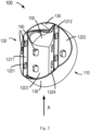
FIG. 2 illustrates a perspective view of amounting bracket 100 according to an embodiment of the present disclosure as viewed from a first perspective view. The mountingbracket 100 may be used to engage themotion sensor 100 to aid in mounting themotion sensor 100 to various positions including walls, corners, ceilings, floors, etc. It will be appreciated that in addition to themotion sensor 100, the mountingbracket 100 may also be used to engage other types of devices to be mounted to assist in mounting the devices to be mounted in place. - As shown in
FIG. 2 , the mountingbracket 100 comprises afirst surface 110 and asecond surface 120. Thefirst surface 110 is adapted to engage themotion sensor 100 or the device to be mounted, and thesecond surface 120 is opposite thefirst surface 110. By way of example, thesecond surface 120 may be attached to a variety of different positions, such as a corner, a wall surface, a ceiling, a floor, etc. In this manner, the mountingbracket 100 may help secure themotion sensor 100 or the device to be mounted in a desired position. -
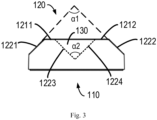
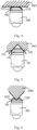
FIG. 3 illustrates a side view of the mountingbracket 100 as viewed in direction A inFIG. 2 ,FIG. 4 illustrates a schematic view of the mountingbracket 100 and themotion sensor 200 mounted to awall surface 2001,FIG. 5 illustrates a schematic view of the mountingbracket 100 and themotion sensor 200 mounted to aninterior wall corner 2002, andFIG. 6 illustrates a schematic view of the mountingbracket 100 and themotion sensor 200 mounted to anexterior wall corner 2003. Hereinafter, the mountingbracket 100 will be described in detail with reference toFIG. 2 to FIG. 6 . - According to an embodiment of the present disclosure, the
second surface 120 of the mountingbracket 100 comprises a first mounting region, wherein the first mounting region is formed as a planar structure and is adapted to be mounted to a planar surface. By way of example, the first mounting region generally appears planar, whereby when the mountingbracket 100 is mounted to a wall, ceiling, floor, or other generally flat mounting position, the first mounting region may be securely attached to the mounting position, thereby helping to secure the mountingbracket 100 and the device to be mounted in place. In some embodiments of the present disclosure, the first mounting region comprises afirst mounting surface 1211 and asecond mounting surface 1212, wherein thefirst mounting surface 1211 and thesecond mounting surface 1212 are separate from each other and extend in the same plane. By providing the two mountingsurfaces bracket 100 is stably placed on the plane surface, and reduce the occupation area of the first mounting region to some extent. - According to embodiments of the present disclosure, the
second surface 120 of the mountingbracket 100 further comprises a second mounting region formed as an angled structure and adapted to be mounted to a non-planar surface. By way of example, the second mounting region as a whole exhibits an angled structure, whereby when the mountingbracket 100 is mounted to a mounting position such as a corner of a wall, the shape of the second mounting region may cooperate with the angled shape of the mounting position to determine that the mountingbracket 100 can be firmly attached to the mounting position. By forming a variety of mounting regions on thesecond surface 120, the mountingbracket 100 may be attached to a variety of different mounting positions, thereby greatly widening the application and scope of the mountingbracket 100. - The second mounting region may comprise a first sub-region and a second sub-region. The first sub-region is formed as a structure with a first angle α1 (see
FIG. 3 ) and adapted to be mounted to aninterior wall corner 2002; thesecond sub-regions FIG. 3 ) and adapted to be mounted to anexterior wall corner 2003. With the first sub-regions and the second sub-regions being provided, the mountingbracket 100 may be mounted to both an interior wall corner and an exterior wall corner, which greatly increases the application scenario of the mountingbracket 100. It will be appreciated that only the first sub-regions or the second sub-regions may also be provided, and that in this case the area of the omitted sub-regions may be used to increase the area of the provided sub-regions and the first mounting region. However, it is more preferable to provide the first mounting region and the first sub-regions and the second sub-regions of the second mounting region at the same time, because this makes the mountingbracket 100 adapted to be mounted in three scenarios, namely, a plane, an interior wall corner and an outer corner, so that the mountingbracket 100 and themotion sensor 200 may be applied to most indoor and outdoor mounting scenarios, which substantially improves the difficulty in mounting themotion sensor 200 and other devices to be mounted. - The first sub-region may include a
third mounting surface 1221 and afourth mounting surface 1222, wherein an extension plane where thethird mounting surface 1221 lies and an extension plane where thefourth mounting surface 1222 lies form a first angle α1 to fit theinterior wall corner 2002. As an example, when the mountingbracket 100 is made abut against theinterior wall corner 2002, thethird mounting surface 1221 and thefourth mounting surface 1222 may abut against two wall surfaces of theinterior wall corner 2002, respectively, thereby securely mounting the mountingbracket 100 to theinterior wall corner 2002. The second sub-region may include afifth mounting surface 1223 and asixth mounting surface 1224 that form a second angle α2 to fit anexterior wall corner 2003. As an example, thefifth mounting surface 1223 and thesixth mounting surface 1224 may abut against two wall surfaces of theexterior wall corner 2003, respectively, thereby securely mounting the mountingbracket 100 to theexterior wall corner 2003. - The
third mounting surface 1221 is located on a side of thefirst mounting surface 1211 away from thesecond mounting surface 1212 and obliquely extends from a first edge of thefirst mounting surface 1211 in a direction toward thefirst surface 110, and thefourth mounting surface 1222 is located on a side of thesecond mounting surface 1212 away from thefirst mounting surface 1211 and obliquely extends from a first edge of thesecond mounting surface 1212 in a direction toward thefirst surface 110. Thefifth mounting surface 1223 and thesixth mounting surface 1224 are located between thefirst mounting surface 1211 and thesecond mounting surface 1212, thefifth mounting surface 1223 extends obliquely from the second edge of thefirst mounting surface 1211 in a direction toward thefirst surface 110, and thesixth mounting surface 1224 extends obliquely from the second edge of thesecond mounting surface 1212 in a direction toward thefirst surface 110. - In this manner, the first to sixth mounting surfaces constitute the
second surface 120 having a continuous surface, wherein thethird mounting surface 1221 and thefifth mounting surface 1223 extend obliquely downward from both sides of thefirst mounting surface 1211, respectively, and thefourth mounting surface 1222 and thesixth mounting surface 1224 extend obliquely downward from both sides of thesecond mounting surface 1212, respectively. Thus, an angled structure matching the interior wall corner is formed on the outside of thesecond surface 120, an angled structure matching the exterior wall corner is formed on the inside of thesecond surface 120, and the raised first mountingsurface 1211 and second mountingsurface 1212 form a planar structure suitable for planar mounting. Such a structure makes full use of the surface area of thesecond surface 120 and ensures that the various mounting regions for interior wall corner mounting, exterior wall corner mounting and planar mounting do not interfere with and affect each other. - In some embodiments of the present disclosure, the first angle α1 and the second angle α2 are right angles. Since the corners of most walls are at right angles, setting the angles as right angles may ensure that the mounting
bracket 100 may be adapted for most wall corner mounting scenarios. It will be appreciated that where the angle of the wall corner is a non-right angle, the first angle α1 and the second angle α2 may also be other angles matching the angle of the wall corner. - In some embodiments of the present disclosure, the mounting
bracket 100 may further comprise a removable first sidewall portion 130 (seeFIG. 2 andFIG. 3 ) that extends from an edge of the second mounting region to a position aligned with the first mounting region. For example, thefirst sidewall portion 130 extends from edges of both sides of thefifth mounting surface 1223 and thesixth mounting surface 1224 to a position aligned with thefirst mounting surface 1211 and thesecond mounting surface 1212. Furthermore, although not shown inFIG. 2 andFIG. 3 , thefirst sidewall portion 130 may also extend from an edge of thethird mounting surface 1221 and/or an edge of thefourth mounting surface 1222 to a position aligned with thefirst mounting surface 1211 and thesecond mounting surface 1212. When the mountingbracket 100 is mounted to a planar surface such as a wall surface, a ceiling, and a floor, thefirst sidewall portion 130 may ensure that the overall appearance of the mountingbracket 100 is complete and aesthetically pleasant, and when the mountingbracket 100 is mounted to the exterior wall corner or interior wall corner, thefirst sidewall portion 130 may be removed, thereby not affecting the mounting of the mountingbracket 100. -
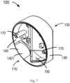
FIG. 7 illustrates a perspective view of the mountingbracket 100 according to an embodiment of the present disclosure as viewed from a second perspective view,FIG. 8 illustrates a bottom view of a side of thefirst surface 110 of the mountingbracket 100 according to an embodiment of the present disclosure; andFIG. 9 illustrates a perspective view of the mountingbracket 100 mounted withwire conduits 300 and themotion sensor 200. - As shown in
FIG. 7 andFIG. 8 , the mountingbracket 100 may further comprise asecond sidewall portion 140. Thesecond sidewall portion 140 extends from edges of the first mounting region and second mounting region in a direction toward thefirst surface 110. For example, thesecond sidewall portion 140 may extend from an edge of one or more of thefirst mounting surface 1211, thesecond mounting surface 1212, thethird mounting surface 1221, thefourth mounting surface 1222, thefifth mounting surface 1223, and thesixth mounting surface 1224 to form an annular wall surrounding thefirst surface 110, and an space formed by the annular wall and thefirst surface 110 may be used to receive themotion sensor 200 or the base of the device to be mounted. Further referring toFIG. 9 , a portion ofsidewall 1401 of thesecond sidewall portion 140 can be removed upon mounting conductor wires orwire conduits 300 to themotion sensor 200 or to the device to be mounted. Specifically, themotion sensor 200 or device to be mounted may need to be connected to a utility grid or other power source through conductor wires orwire conduits 300. To this end, the portion ofside wall 1401 of thesecond sidewall portion 140 may be set removable, e.g., theremovable sidewall 1401 may be set thinner than other portions of thesecond sidewall portion 140, or may be made of a breakable material. Thus, with the portion ofsidewall 1401 being removed, the conductor wires andwire conduits 300 can enter the interior of the mountingbracket 100 in any direction from the side of the mountingbracket 100, so that the mounting and connection of the conductor wires andwire conduits 300 is achieved without destroying or affecting the overall appearance of the mountingbracket 100 andmotion sensor 200. - In some embodiments of the present disclosure, the second sub-regions of the second mounting region are provided with an
opening 150 to enable the conductor wires orwire conduits 300 to pass through the mountingbracket 100 from a side of thesecond surface 120 to a side of thefirst surface 110. For example, the opening 150 (seeFIG. 2, FIG. 2 andFIG. 8 ) may be provided in thefourth mounting surface 1223 and/or thefifth mounting surface 1224, so that the external conductor wires andwire conduits 300 can continue to connect with themotion sensor 200 or device to be mounted through the mountingbracket 100 after passing through theremovable portion 1401 of thesecond sidewall portion 140, or connect with themotion sensor 200 or device to be mounted directly through the mountingbracket 100 without passing through thesecond sidewall portion 140. - In some embodiments of the present disclosure, each sub-region of the first mounting region and the second mounting region is provided with a mounting
hole 160. For example, the mountingholes 160 may be provided on one or both of thefirst mounting surface 1211 and thesecond mounting surface 1212 so as to secure the mountingbracket 100 to a wall, ceiling, floor, or other planar position by screws or bolts when performing the planar mounting shown inFIG. 4 . Similarly, the mountinghole 160 may be provided on one or both of thethird mounting surface 1221 and thefourth mounting surface 1222, and on one or both of thefifth mounting surface 1223 and thesixth mounting surface 1224, to achieve corresponding mounting and securing. In addition, thefirst surface 110 may be provided with mounting studs 170 (seeFIG. 7 andFIG. 8 ). By means of the mountingstuds 170 and corresponding bolts, the mountingbracket 100 may be firmly engaged to the device to be mounted, for example to the base of themotion sensor 100. In some embodiments, the mountingbracket 100 may be integrally formed. In this way, the mountingbracket 100 may be manufactured at a low cost and has the advantage of being robust and reliable. - In embodiments of the present disclosure, the mounting bracket may be mounted to a variety of positions, such as corners, wall surfaces, and ceilings, by providing a variety of mounting regions on the surface of the mounting bracket, which increases the application scenarios and scope of the mounting bracket and the motion sensor or other devices engaged by the mounting bracket. In addition, the mounting bracket of the present disclosure may also conveniently mount conductor wires and wire conduits in multiple directions without affecting the overall appearance.
- Through the teaching given by the above depictions and related figures, many modifications and other embodiments of the present disclosure will be apparent to those skilled in the art. Therefore, it is to be appreciated that the embodiments of the present disclosure are not limited to the disclosed specific embodiments, and modifications and other embodiments are intended to be comprised within the scope of the present disclosure. In addition, while the above description and related figures have described example embodiments in the context of certain example combinations of components and/or functions, it should be appreciated that different combination forms of the components and/or functions may be provided by alternative embodiments without departing from the scope of the present disclosure. In this regard, for example, other combination forms of components and/or functions that are different from those explicitly described above are also contemplated as being within the scope of the present disclosure. Although specific terms are employed herein, they are used in a generic and illustrative sense and are not intended to be limiting.
Claims (12)
- A mounting bracket (100), wherein the mounting bracket (100) comprises:a first surface (110) adapted to engage a device to be mounted; anda second surface (120) being opposite the first surface (110), and comprising:a first mounting region (1211, 1212) formed as a planar structure and adapted to be mounted to a planar surface (2001); anda second mounting region (1221, 1222, 1223, 1224) formed as an angled structure and adapted to be mounted to a non-planar surface (2002, 2003).
- The mounting bracket (100) according to claim 1, wherein the second mounting region (1221, 1222, 1223, 1224) comprises a first sub-region (1221, 1222) and a second sub-region (1223, 1224), the first sub-region (1221, 1222) is formed as a structure with a first angle (α1) and adapted to be mounted to an interior wall corner (2002), and the second sub-regions (1223, 1224) are formed as a structure with a second angle (α2) and adapted to be mounted to an exterior wall corner (2003).
- The mounting bracket (100) according to claim 2, wherein
the first mounting region (1211, 1212) comprises a first mounting surface (1211) and a second mounting surface (1212), and the first mounting surface (1211) and the second mounting surface (1212) are separate from each other and extend in the same plane. - The mounting bracket (100) according to claim 3,wherein the first sub-region (1221, 1222) of the second mounting region (1221, 1222, 1223, 1224) comprises a third mounting surface (1221) and a fourth mounting surface (1222), an extension plane where the third mounting surface (1221) lies and an extension plane where the fourth mounting surface (1222) lies forming the first angle (α1) to fit the interior wall corner (2002); andwherein the second sub-region (1223, 1224) of the second mounting region (1221, 1222, 1223, 1224) comprises a fifth mounting surface (1223) and a sixth mounting surface (1224), the fifth mounting surface (1223) and the sixth mounting surface (1224) forming the second angle (α2) to fit the exterior wall corner (2003).
- The mounting bracket (100) according to claim 4,wherein the third mounting surface (1221) is located on a side of the first mounting surface (1211) away from the second mounting surface (1212) and obliquely extends from a first edge of the first mounting surface (1211) in a direction toward the first surface (110);wherein the fourth mounting surface (1222) is located on a side of the second mounting surface (1212) away from the first mounting surface (1211) and obliquely extends from a first edge of the second mounting surface (1212) in a direction toward the first surface (110); andwherein the fifth mounting surface (1223) and the sixth mounting surface (1224) are located between the first mounting surface (1211) and the second mounting surface (1212), the fifth mounting surface (1223) extends obliquely from a second edge of the first mounting surface (1211) in a direction toward the first surface (110), and the sixth mounting surface (1224) extends obliquely from a second edge of the second mounting surface (1212) in a direction toward the first surface (110).
- The mounting bracket (100) according to any of claims 1-5, wherein the mounting bracket further comprises:
a first sidewall portion (130) extending from an edge of the second mounting region (1221, 1222, 1223, 1224) to a position aligned with the first mounting region (1211, 1212), the first sidewall portion (130) being removable. - The mounting bracket (100) according to any of claims 1-5, wherein the mounting bracket further comprises:
a second sidewall portion (140) extending from edges of the first mounting region (1211, 1212) and the second mounting region (1221, 1222, 1223, 1224) in a direction toward the first surface (110), a portion (1401) of the second sidewall portion (140) being removable. - The mounting bracket (100) according to any of claims 2-5, wherein
the second sub-region (1223, 1224) of the second mounting region (1221, 1222, 1223, 1224) is provided with an opening (150) to enable conductor wires or wire conduits (300) to pass through the mounting bracket (100) from a side of the second surface (120) to a side of the first surface (110). - The mounting bracket (100) according to any of claims 2-5, wherein the first mounting region (1211, 1212) and each sub-region of the second mounting region (1221, 1222, 1223, 1224) are provided with mounting holes (160), and the first surface (110) is provided with mounting studs (170).
- The mounting bracket (100) according to any of claims 1-5, wherein the mounting bracket (100) is integrally formed.
- The mounting bracket (100) according to any of claims 2-5, wherein the first angle (α1) and the second angle (α2) are right angles.
- A sensor assembly (1000), comprising:the mounting bracket (100) according to any of claims 1-11; anda motion sensor (200) engaged to the mounting bracket (100).
Applications Claiming Priority (1)
| Application Number | Priority Date | Filing Date | Title |
|---|---|---|---|
| CN202223544183.2U CN219829940U (en) | 2022-12-29 | 2022-12-29 | Mounting bracket and sensor assembly |
Publications (3)
| Publication Number | Publication Date |
|---|---|
| EP4394232A1 true EP4394232A1 (en) | 2024-07-03 |
| EP4394232B1 EP4394232B1 (en) | 2025-08-13 |
| EP4394232C0 EP4394232C0 (en) | 2025-08-13 |
Family
ID=88274163
Family Applications (1)
| Application Number | Title | Priority Date | Filing Date |
|---|---|---|---|
| EP23307306.3A Active EP4394232B1 (en) | 2022-12-29 | 2023-12-21 | Mounting bracket and sensor assembly |
Country Status (4)
| Country | Link |
|---|---|
| EP (1) | EP4394232B1 (en) |
| CN (1) | CN219829940U (en) |
| AU (1) | AU2023285819B2 (en) |
| ES (1) | ES3048933T3 (en) |
Citations (7)
| Publication number | Priority date | Publication date | Assignee | Title |
|---|---|---|---|---|
| US1219596A (en) * | 1915-08-23 | 1917-03-20 | Manley H Simmons | Sign-holder. |
| DE9303267U1 (en) * | 1993-03-05 | 1993-06-09 | Fa. Peter Kremser, 2000 Hamburg | Mounting base for a lamp or similar. |
| WO1999044472A1 (en) * | 1998-03-03 | 1999-09-10 | Sensormatic Electronics Corporation | Mounting bracket for a camera base |
| JP2001238101A (en) * | 2000-02-22 | 2001-08-31 | Elbex Video Ltd | TV camera |
| GB2384520A (en) * | 2002-01-28 | 2003-07-30 | Everspring Ind Co Ltd | A corner fastening device |
| US20060237603A1 (en) * | 2005-04-11 | 2006-10-26 | Qingdao Minmetals And Machinery, Inc. | Appliance support assembly |
| CN201706162U (en) * | 2010-08-20 | 2011-01-12 | 河南省电力公司漯河供电公司 | Wall-mounted video surveillance camera support |
-
2022
- 2022-12-29 CN CN202223544183.2U patent/CN219829940U/en active Active
-
2023
- 2023-12-20 AU AU2023285819A patent/AU2023285819B2/en active Active
- 2023-12-21 ES ES23307306T patent/ES3048933T3/en active Active
- 2023-12-21 EP EP23307306.3A patent/EP4394232B1/en active Active
Patent Citations (7)
| Publication number | Priority date | Publication date | Assignee | Title |
|---|---|---|---|---|
| US1219596A (en) * | 1915-08-23 | 1917-03-20 | Manley H Simmons | Sign-holder. |
| DE9303267U1 (en) * | 1993-03-05 | 1993-06-09 | Fa. Peter Kremser, 2000 Hamburg | Mounting base for a lamp or similar. |
| WO1999044472A1 (en) * | 1998-03-03 | 1999-09-10 | Sensormatic Electronics Corporation | Mounting bracket for a camera base |
| JP2001238101A (en) * | 2000-02-22 | 2001-08-31 | Elbex Video Ltd | TV camera |
| GB2384520A (en) * | 2002-01-28 | 2003-07-30 | Everspring Ind Co Ltd | A corner fastening device |
| US20060237603A1 (en) * | 2005-04-11 | 2006-10-26 | Qingdao Minmetals And Machinery, Inc. | Appliance support assembly |
| CN201706162U (en) * | 2010-08-20 | 2011-01-12 | 河南省电力公司漯河供电公司 | Wall-mounted video surveillance camera support |
Also Published As
| Publication number | Publication date |
|---|---|
| EP4394232B1 (en) | 2025-08-13 |
| CN219829940U (en) | 2023-10-13 |
| EP4394232C0 (en) | 2025-08-13 |
| AU2023285819A1 (en) | 2024-07-18 |
| ES3048933T3 (en) | 2025-12-12 |
| AU2023285819B2 (en) | 2025-07-17 |
Similar Documents
| Publication | Publication Date | Title |
|---|---|---|
| US20230318274A1 (en) | Weatherproof electrical enclosure with reinforcement | |
| US6164475A (en) | Electrical box for fan or fixture support | |
| US6825414B2 (en) | Exterior mounting block for electrical fixtures | |
| JPH0923534A (en) | Ceiling fan installation distributing box | |
| JP7610670B2 (en) | Partition device | |
| EP4394232B1 (en) | Mounting bracket and sensor assembly | |
| JP2021197234A (en) | Lighting device | |
| KR20060101738A (en) | Connection structure of wiring duct | |
| CN217064255U (en) | Automatically controlled box and air conditioner | |
| JP2021197357A (en) | Lighting device | |
| JP3040257U (en) | Lighting equipment | |
| JP3470187B2 (en) | Outlet box fixture | |
| JP2521117Y2 (en) | Air conditioning pipe cover | |
| JP7787017B2 (en) | Mounting base for alarm | |
| JPH0628917U (en) | Mounting structure for lens and extension | |
| JP2013087601A (en) | Bathroom structure | |
| KR200220988Y1 (en) | Air conditioner body improves installation | |
| JP3129161U (en) | Decorative cover for piping | |
| JPS6310588Y2 (en) | ||
| JP2006321636A (en) | Elevator cab wall fixing structure | |
| JPH041241Y2 (en) | ||
| JP6832733B2 (en) | Lighting device mounting structure in the luggage compartment of the vehicle | |
| JPS6345629Y2 (en) | ||
| JPH0541571Y2 (en) | ||
| JPS641697Y2 (en) |
Legal Events
| Date | Code | Title | Description |
|---|---|---|---|
| PUAI | Public reference made under article 153(3) epc to a published international application that has entered the european phase |
Free format text: ORIGINAL CODE: 0009012 |
|
| STAA | Information on the status of an ep patent application or granted ep patent |
Free format text: STATUS: THE APPLICATION HAS BEEN PUBLISHED |
|
| AK | Designated contracting states |
Kind code of ref document: A1 Designated state(s): AL AT BE BG CH CY CZ DE DK EE ES FI FR GB GR HR HU IE IS IT LI LT LU LV MC ME MK MT NL NO PL PT RO RS SE SI SK SM TR |
|
| STAA | Information on the status of an ep patent application or granted ep patent |
Free format text: STATUS: REQUEST FOR EXAMINATION WAS MADE |
|
| 17P | Request for examination filed |
Effective date: 20250103 |
|
| GRAP | Despatch of communication of intention to grant a patent |
Free format text: ORIGINAL CODE: EPIDOSNIGR1 |
|
| STAA | Information on the status of an ep patent application or granted ep patent |
Free format text: STATUS: GRANT OF PATENT IS INTENDED |
|
| INTG | Intention to grant announced |
Effective date: 20250408 |
|
| GRAS | Grant fee paid |
Free format text: ORIGINAL CODE: EPIDOSNIGR3 |
|
| GRAA | (expected) grant |
Free format text: ORIGINAL CODE: 0009210 |
|
| STAA | Information on the status of an ep patent application or granted ep patent |
Free format text: STATUS: THE PATENT HAS BEEN GRANTED |
|
| AK | Designated contracting states |
Kind code of ref document: B1 Designated state(s): AL AT BE BG CH CY CZ DE DK EE ES FI FR GB GR HR HU IE IS IT LI LT LU LV MC ME MK MT NL NO PL PT RO RS SE SI SK SM TR |
|
| REG | Reference to a national code |
Ref country code: GB Ref legal event code: FG4D |
|
| REG | Reference to a national code |
Ref country code: CH Ref legal event code: EP |
|
| REG | Reference to a national code |
Ref country code: IE Ref legal event code: FG4D |
|
| U01 | Request for unitary effect filed |
Effective date: 20250813 |
|
| U07 | Unitary effect registered |
Designated state(s): AT BE BG DE DK EE FI FR IT LT LU LV MT NL PT RO SE SI Effective date: 20250820 |
|
| REG | Reference to a national code |
Ref country code: ES Ref legal event code: FG2A Ref document number: 3048933 Country of ref document: ES Kind code of ref document: T3 Effective date: 20251212 |
|
| PG25 | Lapsed in a contracting state [announced via postgrant information from national office to epo] |
Ref country code: IS Free format text: LAPSE BECAUSE OF FAILURE TO SUBMIT A TRANSLATION OF THE DESCRIPTION OR TO PAY THE FEE WITHIN THE PRESCRIBED TIME-LIMIT Effective date: 20251213 |
|
| PG25 | Lapsed in a contracting state [announced via postgrant information from national office to epo] |
Ref country code: NO Free format text: LAPSE BECAUSE OF FAILURE TO SUBMIT A TRANSLATION OF THE DESCRIPTION OR TO PAY THE FEE WITHIN THE PRESCRIBED TIME-LIMIT Effective date: 20251113 |
|
| PG25 | Lapsed in a contracting state [announced via postgrant information from national office to epo] |
Ref country code: HR Free format text: LAPSE BECAUSE OF FAILURE TO SUBMIT A TRANSLATION OF THE DESCRIPTION OR TO PAY THE FEE WITHIN THE PRESCRIBED TIME-LIMIT Effective date: 20250813 |
|
| PG25 | Lapsed in a contracting state [announced via postgrant information from national office to epo] |
Ref country code: GR Free format text: LAPSE BECAUSE OF FAILURE TO SUBMIT A TRANSLATION OF THE DESCRIPTION OR TO PAY THE FEE WITHIN THE PRESCRIBED TIME-LIMIT Effective date: 20251114 |
|
| PG25 | Lapsed in a contracting state [announced via postgrant information from national office to epo] |
Ref country code: PL Free format text: LAPSE BECAUSE OF FAILURE TO SUBMIT A TRANSLATION OF THE DESCRIPTION OR TO PAY THE FEE WITHIN THE PRESCRIBED TIME-LIMIT Effective date: 20250813 |
|
| PG25 | Lapsed in a contracting state [announced via postgrant information from national office to epo] |
Ref country code: RS Free format text: LAPSE BECAUSE OF FAILURE TO SUBMIT A TRANSLATION OF THE DESCRIPTION OR TO PAY THE FEE WITHIN THE PRESCRIBED TIME-LIMIT Effective date: 20251113 |
|
| U20 | Renewal fee for the european patent with unitary effect paid |
Year of fee payment: 3 Effective date: 20251223 |
|
| PG25 | Lapsed in a contracting state [announced via postgrant information from national office to epo] |
Ref country code: SM Free format text: LAPSE BECAUSE OF FAILURE TO SUBMIT A TRANSLATION OF THE DESCRIPTION OR TO PAY THE FEE WITHIN THE PRESCRIBED TIME-LIMIT Effective date: 20250813 |
|
| PG25 | Lapsed in a contracting state [announced via postgrant information from national office to epo] |
Ref country code: CZ Free format text: LAPSE BECAUSE OF FAILURE TO SUBMIT A TRANSLATION OF THE DESCRIPTION OR TO PAY THE FEE WITHIN THE PRESCRIBED TIME-LIMIT Effective date: 20250813 |
|
| PG25 | Lapsed in a contracting state [announced via postgrant information from national office to epo] |
Ref country code: SK Free format text: LAPSE BECAUSE OF FAILURE TO SUBMIT A TRANSLATION OF THE DESCRIPTION OR TO PAY THE FEE WITHIN THE PRESCRIBED TIME-LIMIT Effective date: 20250813 |