EP4394212A1 - Method for manufacturing seal body, and seal body - Google Patents
Method for manufacturing seal body, and seal body Download PDFInfo
- Publication number
- EP4394212A1 EP4394212A1 EP22861043.2A EP22861043A EP4394212A1 EP 4394212 A1 EP4394212 A1 EP 4394212A1 EP 22861043 A EP22861043 A EP 22861043A EP 4394212 A1 EP4394212 A1 EP 4394212A1
- Authority
- EP
- European Patent Office
- Prior art keywords
- seal body
- belt
- kneading
- manufacturing
- press
- Prior art date
- Legal status (The legal status is an assumption and is not a legal conclusion. Google has not performed a legal analysis and makes no representation as to the accuracy of the status listed.)
- Pending
Links
Images


Classifications
-
- C—CHEMISTRY; METALLURGY
- C09—DYES; PAINTS; POLISHES; NATURAL RESINS; ADHESIVES; COMPOSITIONS NOT OTHERWISE PROVIDED FOR; APPLICATIONS OF MATERIALS NOT OTHERWISE PROVIDED FOR
- C09K—MATERIALS FOR MISCELLANEOUS APPLICATIONS, NOT PROVIDED FOR ELSEWHERE
- C09K3/00—Materials not provided for elsewhere
- C09K3/10—Materials in mouldable or extrudable form for sealing or packing joints or covers
-
- C—CHEMISTRY; METALLURGY
- C09—DYES; PAINTS; POLISHES; NATURAL RESINS; ADHESIVES; COMPOSITIONS NOT OTHERWISE PROVIDED FOR; APPLICATIONS OF MATERIALS NOT OTHERWISE PROVIDED FOR
- C09J—ADHESIVES; NON-MECHANICAL ASPECTS OF ADHESIVE PROCESSES IN GENERAL; ADHESIVE PROCESSES NOT PROVIDED FOR ELSEWHERE; USE OF MATERIALS AS ADHESIVES
- C09J133/00—Adhesives based on homopolymers or copolymers of compounds having one or more unsaturated aliphatic radicals, each having only one carbon-to-carbon double bond, and at least one being terminated by only one carboxyl radical, or of salts, anhydrides, esters, amides, imides, or nitriles thereof; Adhesives based on derivatives of such polymers
- C09J133/04—Homopolymers or copolymers of esters
- C09J133/06—Homopolymers or copolymers of esters of esters containing only carbon, hydrogen and oxygen, the oxygen atom being present only as part of the carboxyl radical
- C09J133/062—Copolymers with monomers not covered by C09J133/06
-
- B—PERFORMING OPERATIONS; TRANSPORTING
- B29—WORKING OF PLASTICS; WORKING OF SUBSTANCES IN A PLASTIC STATE IN GENERAL
- B29D—PRODUCING PARTICULAR ARTICLES FROM PLASTICS OR FROM SUBSTANCES IN A PLASTIC STATE
- B29D99/00—Subject matter not provided for in other groups of this subclass
- B29D99/0053—Producing sealings
-
- B—PERFORMING OPERATIONS; TRANSPORTING
- B29—WORKING OF PLASTICS; WORKING OF SUBSTANCES IN A PLASTIC STATE IN GENERAL
- B29D—PRODUCING PARTICULAR ARTICLES FROM PLASTICS OR FROM SUBSTANCES IN A PLASTIC STATE
- B29D99/00—Subject matter not provided for in other groups of this subclass
- B29D99/0082—Producing articles in the form of closed loops, e.g. rings
- B29D99/0085—Producing articles in the form of closed loops, e.g. rings for sealing purposes
-
- C—CHEMISTRY; METALLURGY
- C08—ORGANIC MACROMOLECULAR COMPOUNDS; THEIR PREPARATION OR CHEMICAL WORKING-UP; COMPOSITIONS BASED THEREON
- C08F—MACROMOLECULAR COMPOUNDS OBTAINED BY REACTIONS ONLY INVOLVING CARBON-TO-CARBON UNSATURATED BONDS
- C08F220/00—Copolymers of compounds having one or more unsaturated aliphatic radicals, each having only one carbon-to-carbon double bond, and only one being terminated by only one carboxyl radical or a salt, anhydride ester, amide, imide or nitrile thereof
- C08F220/02—Monocarboxylic acids having less than ten carbon atoms; Derivatives thereof
- C08F220/10—Esters
- C08F220/12—Esters of monohydric alcohols or phenols
- C08F220/16—Esters of monohydric alcohols or phenols of phenols or of alcohols containing two or more carbon atoms
- C08F220/18—Esters of monohydric alcohols or phenols of phenols or of alcohols containing two or more carbon atoms with acrylic or methacrylic acids
- C08F220/1802—C2-(meth)acrylate, e.g. ethyl (meth)acrylate
-
- C—CHEMISTRY; METALLURGY
- C09—DYES; PAINTS; POLISHES; NATURAL RESINS; ADHESIVES; COMPOSITIONS NOT OTHERWISE PROVIDED FOR; APPLICATIONS OF MATERIALS NOT OTHERWISE PROVIDED FOR
- C09K—MATERIALS FOR MISCELLANEOUS APPLICATIONS, NOT PROVIDED FOR ELSEWHERE
- C09K3/00—Materials not provided for elsewhere
- C09K3/10—Materials in mouldable or extrudable form for sealing or packing joints or covers
- C09K3/1006—Materials in mouldable or extrudable form for sealing or packing joints or covers characterised by the chemical nature of one of its constituents
-
- F—MECHANICAL ENGINEERING; LIGHTING; HEATING; WEAPONS; BLASTING
- F16—ENGINEERING ELEMENTS AND UNITS; GENERAL MEASURES FOR PRODUCING AND MAINTAINING EFFECTIVE FUNCTIONING OF MACHINES OR INSTALLATIONS; THERMAL INSULATION IN GENERAL
- F16J—PISTONS; CYLINDERS; SEALINGS
- F16J15/00—Sealings
- F16J15/02—Sealings between relatively-stationary surfaces
- F16J15/06—Sealings between relatively-stationary surfaces with solid packing compressed between sealing surfaces
- F16J15/10—Sealings between relatively-stationary surfaces with solid packing compressed between sealing surfaces with non-metallic packing
- F16J15/108—Special methods for making a non-metallic packing
-
- F—MECHANICAL ENGINEERING; LIGHTING; HEATING; WEAPONS; BLASTING
- F16—ENGINEERING ELEMENTS AND UNITS; GENERAL MEASURES FOR PRODUCING AND MAINTAINING EFFECTIVE FUNCTIONING OF MACHINES OR INSTALLATIONS; THERMAL INSULATION IN GENERAL
- F16J—PISTONS; CYLINDERS; SEALINGS
- F16J15/00—Sealings
- F16J15/16—Sealings between relatively-moving surfaces
- F16J15/32—Sealings between relatively-moving surfaces with elastic sealings, e.g. O-rings
- F16J15/3284—Sealings between relatively-moving surfaces with elastic sealings, e.g. O-rings characterised by their structure; Selection of materials
-
- G—PHYSICS
- G01—MEASURING; TESTING
- G01M—TESTING STATIC OR DYNAMIC BALANCE OF MACHINES OR STRUCTURES; TESTING OF STRUCTURES OR APPARATUS, NOT OTHERWISE PROVIDED FOR
- G01M3/00—Investigating fluid-tightness of structures
- G01M3/02—Investigating fluid-tightness of structures by using fluid or vacuum
- G01M3/04—Investigating fluid-tightness of structures by using fluid or vacuum by detecting the presence of fluid at the leakage point
- G01M3/16—Investigating fluid-tightness of structures by using fluid or vacuum by detecting the presence of fluid at the leakage point using electric detection means
- G01M3/18—Investigating fluid-tightness of structures by using fluid or vacuum by detecting the presence of fluid at the leakage point using electric detection means for pipes, cables or tubes; for pipe joints or seals; for valves; for welds; for containers, e.g. radiators
- G01M3/183—Investigating fluid-tightness of structures by using fluid or vacuum by detecting the presence of fluid at the leakage point using electric detection means for pipes, cables or tubes; for pipe joints or seals; for valves; for welds; for containers, e.g. radiators for pipe joints or seals
-
- B—PERFORMING OPERATIONS; TRANSPORTING
- B29—WORKING OF PLASTICS; WORKING OF SUBSTANCES IN A PLASTIC STATE IN GENERAL
- B29K—INDEXING SCHEME ASSOCIATED WITH SUBCLASSES B29B, B29C OR B29D, RELATING TO MOULDING MATERIALS OR TO MATERIALS FOR MOULDS, REINFORCEMENTS, FILLERS OR PREFORMED PARTS, e.g. INSERTS
- B29K2033/00—Use of polymers of unsaturated acids or derivatives thereof as moulding material
- B29K2033/04—Polymers of esters
-
- B—PERFORMING OPERATIONS; TRANSPORTING
- B29—WORKING OF PLASTICS; WORKING OF SUBSTANCES IN A PLASTIC STATE IN GENERAL
- B29K—INDEXING SCHEME ASSOCIATED WITH SUBCLASSES B29B, B29C OR B29D, RELATING TO MOULDING MATERIALS OR TO MATERIALS FOR MOULDS, REINFORCEMENTS, FILLERS OR PREFORMED PARTS, e.g. INSERTS
- B29K2105/00—Condition, form or state of moulded material or of the material to be shaped
- B29K2105/0002—Condition, form or state of moulded material or of the material to be shaped monomers or prepolymers
-
- B—PERFORMING OPERATIONS; TRANSPORTING
- B29—WORKING OF PLASTICS; WORKING OF SUBSTANCES IN A PLASTIC STATE IN GENERAL
- B29K—INDEXING SCHEME ASSOCIATED WITH SUBCLASSES B29B, B29C OR B29D, RELATING TO MOULDING MATERIALS OR TO MATERIALS FOR MOULDS, REINFORCEMENTS, FILLERS OR PREFORMED PARTS, e.g. INSERTS
- B29K2105/00—Condition, form or state of moulded material or of the material to be shaped
- B29K2105/24—Condition, form or state of moulded material or of the material to be shaped crosslinked or vulcanised
-
- C—CHEMISTRY; METALLURGY
- C08—ORGANIC MACROMOLECULAR COMPOUNDS; THEIR PREPARATION OR CHEMICAL WORKING-UP; COMPOSITIONS BASED THEREON
- C08F—MACROMOLECULAR COMPOUNDS OBTAINED BY REACTIONS ONLY INVOLVING CARBON-TO-CARBON UNSATURATED BONDS
- C08F2810/00—Chemical modification of a polymer
- C08F2810/20—Chemical modification of a polymer leading to a crosslinking, either explicitly or inherently
Definitions
- a member called an endless seal body or a sealing device such as an O-ring is attached to a ring-shaped groove (an annular groove) provided on one member side of two members opposed to each other and fastened to each other such as a shaft and a bearing.
- the Patent Document 1 discloses an O-ring molding die for forming an annular O-ring, wherein the O-ring molding die has a pair of molds (upper and lower molds) of the same shape that are symmetrical to a parting line, and the upper mold and lower side are superposed in a state in which the upper mold and the lower side are aligned with each other, and in a state of being mold clamped, an annular molding recessed part capable of configuring a planar annular O-ring vulcanization molding space is provided on the molding surfaces of the upper and lower molds, respectively.
- the O-ring molding die has a pair of molds (upper and lower molds) of the same shape that are symmetrical to a parting line, and the upper mold and lower side are superposed in a state in which the upper mold and the lower side are aligned with each other, and in a state of being mold clamped, an annular molding recessed part capable of configuring a planar annular O-ring vulcanization molding space is provided
- the sealing structure is constructed using the reaction force of the seal body, depending on the size and shape of the seal body, there is a possibility that housing may be loaded, and there is a possibility that a housing or an attachment groove formed in the housing may be deformed or the like.
- the compound 2 to be the main raw material of the seal body 8 includes, for example, a constitutional unit of acrylic monomer derivation (an acrylic monomer derived constitutional unit) derived from an acrylic monomer and a constitutional unit of halogen group-containing monomer derivation (a halogen group-containing monomer derived constitutional unit) derived from a halogen group-containing monomer, and an acrylic rubber or the like configured to include each of these constitutional units as a repeating unit can be used.
- a mill kneader for kneading the mixture 4 by using a rotor blade connected to a driving motor and rotating the rotor blade, a roll kneader (not shown) for kneading the mixture 4 between a plurality of rolls, and the like can be used.
- the kneading step S2 can be carried out in two steps using the above-described mill kneader and roll kneader as kneaders.
- a roll kneading step S2b in which the mill kneaded material 5a obtained by the mill kneading step S2a is defined as a second step, and is further kneaded using a roll kneader as a kneader, can be performed.
- the kneading conditions for the mixture 4 in the kneading step S2 are not particularly limited, and for example, the rotational speed of the rotor blade in the mill kneader that performs the mill kneading step S2a can be set to a range of 5rpm to 20rpm, the kneading temperature can be set to a range of 30°C to 70°C, and the kneading time can be set to a range of 30 minutes to 60 minutes, or the rotational speed of the roll in the roll kneader that performs the roll kneading step S2b can be set to a range of 7rpm to 20rpm, the kneading temperature can be set to a range of 30°C to 80°C, and the kneading time can be set to a range of 10 minutes to 30 minutes.
- the mixture 4 delivered to the kneading step S2 is adjusted to a material having an appropriate viscosity and fluidity for performing the subsequent step.
- the pressurizing conditions of the press machine in the pressurizing step S3 are not particularly limited, and by performing a press in a well-known press mold at, for example, pressurizing pressure: 95 to 105kgf/cm 2 , pressurizing temperature: 150°C, pressurizing time: 1 hour, or the like, a pressurized body 6 in which the pressurized body thickness t after pressurizing is adjusted to the thickness of 2mm can be formed.
- the belt-like body forming step in the method 1 for manufacturing a seal body of the present embodiment is configured to include a cutting step S4 of cutting the thin plate-shaped pressurized body 6 pressed so as to have a uniform pressurized body thickness t (e.g., the thickness of 2mm) by the pressurizing step S3 into a belt-like body 7 (see FIG. 2(b) ).
- one end 7a and the other end 7b are provided at both longitudinal ends. That is, by the cutting step S4, an ended-shaped belt-like body 7 having a pair of ends 7a and 7b is formed.
- the belt-like body 7 is deformed in a predetermined direction (the arrow direction in FIG. 2(c) ) so as to bring the one end 7a and the other end 7b of the belt-like body 7 close to each other, and press-fixing is performed in such a deformed condition.
- the belt-like body 7 is made of a compound 2 such as acrylic rubber that has undergone the kneading step S2 and the pressurizing step S3 included in the belt-like body forming step as a main raw material, and has a property of being freely deformable as described above.
- a compound 2 or the like such as an acrylic rubber containing a halogen group-containing monomer as a constitutional unit is used as a main raw material, thereby it is possible to form an annular (endless) seal body 8 using a self-healing function by forming the material into a belt-like shape, and then bonding the ends 7a and 7b together. Therefore, there is no need for a mold unlike in the manufacturing of the conventional seal body, and the manufacturing costs and the like for such a mold can be reduced. Further, there is no excessive load on the housing side to which the seal body 8 is attached, and a processing step of providing a groove or the like in the housing can be omitted.
- the sealing bodies of Examples 1 to 9 and Comparative Examples 1 to 2 were prepared by using an acrylic rubber (corresponding to the compound in the present invention) described in Table 1 shown below as a main raw material and adding a crosslinking agent to the acrylic rubber, followed by kneading, pressurizing, and cutting steps included in the belt-like body forming step.
- the thin plate-shaped pressurized body subjected to the pressurizing step is cut into the predetermined shape and size, and samples for evaluation are prepared, respectively.
- Example 1 to 9 and Comparative Examples 1 to 2 were kneaded by using a mill-kneader (Labo Plastomill 30C150: manufactured by Toyo Seiki Co., Ltd.).
- the kneading conditions were adjusted such that the rotational speed of the rotor blade was 10rpm and the temperature at the time of kneading was 60°C or less, and kneading was performed for a kneading time of 20 minutes.
- a test piece 9 (see FIG. 3(a) ) having a dumbbell-shaped No. 8 size defined in JIS K6251:2017 (Rubber, vulcanized or thermoplastic-Determination of tensile stress-strain properties) was punched out from the thin plate-shaped pressurized bodies having a thickness of 2mm of Examples 1 to 9 and Comparative Examples 1 to 2 obtained by the pressurizing step, respectively, and was prepared as a measurement sample for evaluating the self-healing function.
- the center part of the obtained test piece 9 was cut with a knife, after dividing into the cutting test piece 11a having a cut surface 10a and the cutting test piece 11b having a cut surface 10b (see FIG.
- Example 2 As shown in Table 2 below, it was shown that the measurement samples of Example 1 to 9, in which the addition amount of the crosslinking agent to be added to 100 parts by weight of the acrylic rubber corresponding to the scope of rights of the method for manufacturing a seal body of the present invention corresponds to 1.0 to 20.6 parts by weight (0.2 to 4 in terms of molar equivalent), were capable of forming a seal body (corresponding to "good” in Table 2). That is, by heating in a state of press-fixing and bonding, the cut surfaces 10a and 10b were bonded to each other, resulting in an integrated state.
- the measurement sample after heating was subjected to a tensile test using a tensile tester (Autograph AG-X: manufactured by Shimadzu Corporation) under the following conditions.
- Self-healing rate (%) [Tensile strength (N) of measurement sample for evaluation] / [Tensile strength (N) of sample for comparison] ⁇ 100
- the seal body manufactured by the method for manufacturing a seal body of the present invention is excellent in self-healing rate. Therefore, it was confirmed that after cutting to a predetermined size, by performing a press-fixing step (or press-fixing/heating step) for heating by press-fixing one end and the other end to each other, the ends are integrated to exhibit sufficient strength. Therefore, it becomes possible to use as a seal body, and it is possible to exhibit high sealability, in other words, sufficient sealing performance.
- Compression test pieces (not shown) for the compression test evaluation of 15mm ⁇ 15mm ⁇ 8mm were prepared from thin plate-shaped pressurized bodies having a thickness of 8mm of Examples 1 to 9 obtained by the pressurizing step (however, using a pressing mold having a thickness of 8mm), respectively.
- the obtained compression test piece was subjected to the compression test using a tensile tester (Autograph AG-IS 100kN: manufactured by Shimadzu Corporation) under the following conditions.
- the measurement samples for evaluation for evaluating the adhesiveness and peelability were prepared from the pressurized bodies of Examples 1 to 9 and Comparative Examples 1 to 2 obtained by the pressurizing step, respectively, and the tensile strength test was performed using a peel strength tester (LTS-200N-S100: manufactured by Minebea Co., Ltd.) after pressurization under the following conditions.
- Measurement sample 12 for evaluation for evaluating the adhesiveness and peelability having a length of 50mm to 70mm, a width of 18mm, a thickness of 2mm, and an adhesive part with a size of 18mm ⁇ 18mm, was prepared from a thin plate-like pressurized body having a thickness of 2mm of Examples 1 to 9 and Comparative examples 1 to 2.
- plate shape bodies 13a, 13b, and 13c of different materials each made of acrylonitrile-butadiene rubber (hereinafter referred to as "NBR"), nylon, and aluminium, each having the same size as the measurement sample 12 for evaluation to be evaluated for the adhesiveness and peelability and having a length of 50mm to 70mm, a width of 18mm, and a thickness of 2mm, were prepared.
- NBR acrylonitrile-butadiene rubber
- a plate shape body 13a or the like of a different material is placed, and only the upper surface of the area facing an adhesive part 14 of the measurement sample 12 for evaluation is exposed, and the other upper surface stacked so as to be covered with the fluororesin sheet 15. Further, the adhesive part 14 of 18mm ⁇ 18mm of the measurement sample 12 for evaluation is placed at the position of the exposed area 16 of the plate shape body 13a or the like of a different material not covered with the fluororesin sheet 15 so as to overlap, and the stainless-steel plate 17, which is adjusted to the size of 18mm ⁇ 18mm, is further placed on the top of the adhesive part 14.
- the weight 18 of 3.3kg is placed on the stainless-steel plate 17, and the load (pressure) of the weight 18 is applied only on the adhesive part 14 (see FIG. 4 ).
- the plate shape body 13a or the like of a different material, the fluororesin sheet 15, the measurement sample 12 for evaluation, the stainless-steel plate 17, and the weight 18 are stacked from below is formed, and the adhesive part 14 of the measurement sample 18 for evaluation and the exposed area 16 of the plate shape body 13a or the like of a different material are brought into close contact with each other by the load of the weight 18.
- the stacked body is put into an oven (not shown) while maintaining such an adhesion state, and is heated at a heating temperature of 100°C under atmospheric pressure for 24 hours. After 24 hours have elapsed, the stacked body is taken out of the oven, and the adhesiveness and peelability of the measurement sample for evaluation 12 to the plate shape body 13a or the like of a different material in the adhesive part 14 and the exposed area 16 are evaluated by the peel strength test.
- the seal body manufactured by the method for manufacturing a seal body of the present invention has high peel strength against different materials. That is, it was shown that the peel strength against different materials of NBR, nylon, and aluminium was higher than the peel strength of Comparative Example 2. Therefore, it becomes possible to use as a seal body, and it is possible to exhibit high sealability, in other words, sufficient sealing performance.
- Water resistance was evaluated using a submergence test jig 19 shown in FIG. 5 , and a water resistance measurement sample 20 made of an endless seal body shown in FIG. 6 (prepared by adding 0.37 equivalent amounts of 1-methylimidazole to a chlorine group-type acrylic rubber). More specifically, the submergence test jig 19 for evaluating the water resistance was constructed by combining a vertical pipe 21 and a horizontal pipe 22, and was adjusted so that the pipe water depth H was 1m.
- the sample 24 which is formed by arranging an acrylic cylindrical member 23a above and SUS cylindrical member 23b below, sandwiching a water resistance measurement sample 20 between the acrylic cylindrical member 23a and the SUS cylindrical member 23b by adjusting the compression rate to be 10%, was left to stand in a pipe bottom 26 of a pipe inner space 25, and held in such a standing condition for 30 minutes.
- the water resistance measurement sample 20 has an endless shape having a joining part 27 which is press-fixed, and a water leakage detection seal 28 capable of detecting water leakage by the contact with water is disposed in an inner space (annular space) surrounded by the water resistance measurement sample 20.
- FIG. 6 shows a drawing in which the acrylic cylindrical member 23a is removed and the water resistance measurement sample 20 is viewed from above.
- the water resistance measurement sample 20 was taken out from the submergence test jig 19, and the presence or absence of water leakage to the water leakage detection seal 28 was visually confirmed to have water resistance equivalent to IPX7.
Landscapes
- Engineering & Computer Science (AREA)
- Chemical & Material Sciences (AREA)
- Mechanical Engineering (AREA)
- General Engineering & Computer Science (AREA)
- Organic Chemistry (AREA)
- Materials Engineering (AREA)
- Medicinal Chemistry (AREA)
- Polymers & Plastics (AREA)
- Chemical Kinetics & Catalysis (AREA)
- Health & Medical Sciences (AREA)
- Physics & Mathematics (AREA)
- General Physics & Mathematics (AREA)
- Sealing Material Composition (AREA)
- Gasket Seals (AREA)
Abstract
Description
- The present invention relates to a method for manufacturing a seal body and a seal body. More specifically, the present invention relates to a method for manufacturing a seal body having an endless shape (or an annular shape) that has a self-healing function and can be manufactured without requiring a molding process using a mold, and a seal body that can be manufactured using the manufacturing method.
- Conventionally, in order to prevent leakage of a fluid such as a liquid such as water or oil or a gas, or to prevent impurities such as dirt and dust from entering from outside, for example, a member called an endless seal body or a sealing device such as an O-ring is attached to a ring-shaped groove (an annular groove) provided on one member side of two members opposed to each other and fastened to each other such as a shaft and a bearing.
- By attaching such a seal body, a gap (space) formed between the two members can be physically closed, and a sealing structure can be constructed to prevent fluid or contaminants from entering to the gap and to restrict flow of fluid or the like between the two members.
- The seal body is mainly formed of a rubber-like elastic body such as a hard rubber which is elastically deformable, and is mainly manufactured by pouring a raw material of a rubber-like elastic body having fluidity into a cavity of a mold which is previously engraved into a predetermined shape, curing the raw material by cooling or the like in the mold, and then demolding from the cavity of the mold (for example, refer to Patent Document 1). The seal body thus obtained is provided with an elastic force and a repulsive force caused by the rubber-like elastic body of the raw material, whereby it is possible to seal between the two members. In order to construct a sealing structure, a large number of seal bodies having an annular shape, in other words, an endless shape, such as the O-ring described above, have been manufactured.
- A method for manufacturing a seal body having an annular shape, such as an O-ring, will be explained in more detail. The Patent Document 1 discloses an O-ring molding die for forming an annular O-ring, wherein the O-ring molding die has a pair of molds (upper and lower molds) of the same shape that are symmetrical to a parting line, and the upper mold and lower side are superposed in a state in which the upper mold and the lower side are aligned with each other, and in a state of being mold clamped, an annular molding recessed part capable of configuring a planar annular O-ring vulcanization molding space is provided on the molding surfaces of the upper and lower molds, respectively.
- [Patent Document 1]
JP-A- 2002-264004 - As described above, in the case of a general seal body, since a mold (for example, a molding die) is used for processing into a predetermined shape, a manufacturing cost for manufacturing the molding die or the like may be required. In addition, in the case of a general annular seal body, it is necessary to form an attachment groove to attach the seal body in advance on the housing side to be attached, a processing step for providing such an attachment groove is required, the number of work steps may be increased and a processing cost for providing an attachment groove may be further required.
- In addition, since the sealing structure is constructed using the reaction force of the seal body, depending on the size and shape of the seal body, there is a possibility that housing may be loaded, and there is a possibility that a housing or an attachment groove formed in the housing may be deformed or the like.
- Here, as the seal body and the sealing device, those using solid seal bodies as described above were mainly exemplified and explained, but the seal body is not limited to this, for example, it is also performed to construct a sealing structure using a liquid-like gasket called a "liquid gasket".
- However, in the case of a liquid gasket, it is necessary to apply a liquid material to a surface to be processed on which two members for obtaining a sealing structure overlap each other, and it is sometimes troublesome to form a liquid gasket such as protruding from a surface to be processed or flowing in the coating. In addition, since a large amount of time is required to affect the liquid gasket after the liquid material is applied, there is a possibility that the working time becomes long, and when the curing of the liquid gasket is completed, problems such as not being able to easily removed may occur.
- In view of the above circumstances, an object of the present invention is to provide a method for manufacturing a seal body for manufacturing an endless (annular) seal body that has excellent attachability, can suppress manufacturing costs and processing costs, and does not apply an excessive load to a housing to be attached, and a seal body manufactured using the manufacturing method.
- According to the present invention, a method for manufacturing a seal body and a seal body that solve the above-described problems are provided below.
- [1] A method for manufacturing a seal body whose main raw material is a compound containing a halogen group-containing monomer as a constitutional unit, the method includes a belt-like body forming step of adding a crosslinking agent to the compound to form a belt-like body from the obtained mixture, and a press-fixing step of press-fixing one end and the other end of the belt-like body obtained by the belt-like body forming step to form an endless seal body.
- [2] The method for manufacturing a seal body according to [1], wherein, in the belt-like body forming step, the crosslinking agent is added so that the molar equivalent of the crosslinking agent with respect to a halogen group of the halogen group-containing monomer contained in the compound is in the range of 0.2 to 4.0.
- [3] The method for manufacturing a seal body according to [1] or [2], wherein the belt-like body forming step includes two stages of kneading step including: a mill kneading step using a mill kneader which kneads the mixture using a rotor blade, and a roll kneading step using a roll kneader which kneads a mill kneaded material obtained by the mill kneading step between a plurality of rolls.
- [4] The method for manufacturing a seal body according to [3], wherein the kneading conditions for the kneading step are as follows: the rotational speed of the rotor blade of the mill kneader performing the mill kneading step is in the range of 5rpm to 20rpm, the kneading temperature is in the range of 30°C to 70°C, and the kneading time is in the range of 30 minutes to 60 minutes, and the rotational speed of the roll of the roll kneader performing the roll kneading step is in the range of 7rpm to 20rpm, the kneading temperature is in the range of 30°C to 80°C, and the kneading time is in the range of 10 minutes to 30 minutes.
- [5] The method for manufacturing a seal body according to any one of [1] to [4], wherein the belt-like body forming step includes a pressurizing step of pressurizing using a press machine, and the pressurizing conditions of the pressurizing step are such that the pressurizing pressure of the press machine is in the range of 95 to 105kgf/cm2, the pressurizing temperature is 150°C, the pressurizing time is 1 hour, and the thickness of the pressurized body after the pressurizing is adjusted to the thickness of 2mm.
- [6] The method for manufacturing a seal body according to any one of [1] to [5], wherein the press-fixing step further includes a press-fixing/heating step of press-fixing the one end and the other end of the belt-like body and then heating the belt-like body at 100°C for 24 hours in the atmosphere.
- [7] A seal body manufactured by the method for manufacturing a seal body according to any one of [1] to [6], wherein the compound includes an acrylic monomer derived constitutional unit derived from an acrylic monomer and a halogen group-containing monomer derived constitutional unit derived from the halogen group-containing monomer.
- [8] The seal body according to [7], wherein the acrylic monomer is ethyl acrylate, the halogen group-containing monomer is 2-chloroethyl vinyl monomer, and the crosslinking agent is imidazole.
- [9] The seal body according to [7] or [8], wherein the self-healing rate is 50% or more.
- [10] The seal body according to any one of [7] to [9], wherein the adhesive strength to acrylonitrile-butadiene rubber is 0.30N/mm or more and 0.70N/mm or less.
- [11] The seal body according to any one of [7] to [10], wherein the adhesive strength to nylon is 0.30N/mm or more and 0.50N/mm or less.
- [12] The seal body according to any one of [7] to [11], wherein the adhesive strength to aluminium of 0.10N/mm or more and 0.40N/mm or less.
- [13] The seal body according to any one of [7] to [12], wherein the reaction force at the time of 40% shrinkage is 200N or less.
- [14] The seal body according to any one of [7] to [13], which has water resistance equivalent to IPX7.
- According to the method for manufacturing a seal body of the present invention, it is possible to form an endless seal body by using a compound such as an acrylic rubber containing a halogen group-containing monomer as a main raw material and press-fixing one end and the other end of the belt-like body formed by the belt-like body forming step. Accordingly, it is not necessary to use a conventional molding die, and an endless (annular) seal body can be easily formed with a reduced manufacturing cost. In addition, the obtained seal body has a self-healing function, thereby exhibiting excellent attachability and not being excessively loaded on a housing.
-
-
FIG. 1 is an explanatory drawing schematically showing a flow of a method for manufacturing a seal body of one embodiment of the present invention. -
FIG. 2 is an explanatory drawing showing a schematic configuration of (a) pressurized body, (b) belt-like body, (c) press-fixing between ends of the belt-like body, and an endless seal body. -
FIG. 3 is an explanatory drawing showing a schematic configuration of (a) test piece, (b) test cut piece, (c) measurement sample for evaluation for evaluating the self-healing function of the tensile test. -
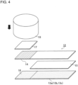
FIG. 4 is an explanatory drawing showing a schematic configuration of the adjustment of the measurement sample for evaluation for evaluating the adhesiveness and peelability. -
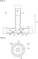
FIG. 5 is an explanatory drawing showing a schematic configuration of a submergence test jig. -
FIG. 6 is an explanatory drawing showing a schematic configuration of a water resistance measurement sample. - Hereinafter, embodiments of a method for manufacturing a seal body and a seal body of the present invention will be described in detail with reference to the drawings. It should be noted that the method for manufacturing seal body and the seal body of the embodiments of the present invention are not limited to those shown below, and various design changes, modifications, improvements, and the like can be made without departing from the gist of the present invention.
- As shown in
FIGs. 1 to 6 , a method 1 for manufacturing a seal body of an embodiment of the present invention includes acompound 2 containing a halogen group-containing monomer as a constitutional unit as a main raw material, and is mainly composed of a belt-like body forming step of adding a crosslinking agent 3 to thecompound 2 to form a belt-like body 7 from the obtainedmixture 4, and a press-fixing step S5 of press-fixing oneend 7a and theother end 7b of the belt-like body 7 obtained by the belt-like body forming step to form an endless seal body 8. - The
compound 2 to be the main raw material of the seal body 8 includes, for example, a constitutional unit of acrylic monomer derivation (an acrylic monomer derived constitutional unit) derived from an acrylic monomer and a constitutional unit of halogen group-containing monomer derivation (a halogen group-containing monomer derived constitutional unit) derived from a halogen group-containing monomer, and an acrylic rubber or the like configured to include each of these constitutional units as a repeating unit can be used. Further, as the acrylic monomer (acrylic monomer derived constitutional unit), for example, ethyl acrylate, butyl acrylate, methoxyethyl acrylate and the like can be used, while as the halogen group-containing monomer (halogen group-containing monomer derived constitutional unit), for example, 2-chloroethyl vinyl monomer such as 2-chloroethyl vinyl ether can be used. As the halogen group in the halogen group-containing monomer, a fluorine group, a butyl group, an iodine group, or the like may be used in addition to the above-described chlorine group. - The belt-like body forming step in the method 1 for manufacturing a seal body of the present embodiment is configured to include a crosslinking agent adding step S1 in which a predetermined addition amount of a crosslinking agent 3 is added to the
compound 2 as the main raw material containing the halogen group-containing monomer, and theacrylic rubber 2 and the crosslinking agent 3 are uniformly mixed using a well-known stirrer (not shown) to form amixture 4. Here, as the crosslinking agent 3, for example, an imidazole compound such as 1-butylimidazole can be added and used. That is, any crosslinking agent 3 can be used as long as it can be added to thecompound 2 such as acrylic rubber and can be uniformly mixed, and the crosslinking reaction can proceed with thecompound 2. - Here, the addition amount of the crosslinking agent 3 to the
compound 2 in the crosslinking agent adding step S1 can be defined based on the following. That is, the molar equivalent of the crosslinking agent 3 to the halogen group of the halogen group-containing monomer contained in theacrylic rubber 2 may be in the range of 0.2 to 4.0. - When the range of such molar equivalents is converted into mol%, the addition amount of the crosslinking agent 3 may be in the range of 0.8mol% to 4.2mol% with respect to the addition amount of the
acrylic rubber 2. By adding the crosslinking agent 3 having the molar equivalent (or mol%) of as defined above, thecompound 2 can accelerate good crosslinking reaction. - The belt-like body forming step in the method 1 for manufacturing a seal body of the present embodiment is configured to include a kneading step S2 in which a specified amount of the crosslinking agent 3 is added by the crosslinking agent adding step S1, and the
mixture 4 obtained by stirring with theacrylic rubber 2 and mixing the mixture so as to be uniform is further kneaded. Here, the kneading step S2 can be carried out using a well-known kneader, and is not particularly limited, and themixture 4 is kneaded and adjusted to a predetermined viscosity. - For example, a mill kneader (not shown) for kneading the
mixture 4 by using a rotor blade connected to a driving motor and rotating the rotor blade, a roll kneader (not shown) for kneading themixture 4 between a plurality of rolls, and the like can be used. - Further, the kneading step S2 can be carried out in two steps using the above-described mill kneader and roll kneader as kneaders. Specifically, a mill kneading step S2a in which the
mixture 4 obtained by the crosslinking agent adding step S 1 is defined as a first step, and is kneaded using a mill kneader as a kneader, and a roll kneading step S2b in which the mill kneadedmaterial 5a obtained by the mill kneading step S2a is defined as a second step, and is further kneaded using a roll kneader as a kneader, can be performed. Incidentally, the kneading step S2 is not limited to the above, and may be only one of the mill kneading step S2a and the roll kneading step S2b, or may be one in which the roll kneading step S2b is performed prior to the mill kneading step S2a. - Here, the kneading conditions for the
mixture 4 in the kneading step S2 are not particularly limited, and for example, the rotational speed of the rotor blade in the mill kneader that performs the mill kneading step S2a can be set to a range of 5rpm to 20rpm, the kneading temperature can be set to a range of 30°C to 70°C, and the kneading time can be set to a range of 30 minutes to 60 minutes, or the rotational speed of the roll in the roll kneader that performs the roll kneading step S2b can be set to a range of 7rpm to 20rpm, the kneading temperature can be set to a range of 30°C to 80°C, and the kneading time can be set to a range of 10 minutes to 30 minutes. - In this way, by performing the kneading by the kneading step S2 described above (the mill kneading step S2a and the roll kneading step S2b), the
mixture 4 delivered to the kneading step S2 is adjusted to a material having an appropriate viscosity and fluidity for performing the subsequent step. - The belt-like body forming step in the method 1 for manufacturing a seal body of the present embodiment is configured to include a pressurizing step S3 of pressurizing the kneaded
material 5 obtained by the kneading step S2 using a press machine. In the pressurizing step S3, it is possible to use a well-known press machine, and by applying pressure while being heated at a predetermined pressurizing pressure, for example, an aggregated kneadedmaterial 5 delivered from the kneading step S2 is thinly stretched to a predetermined thickness to form a thin plate-shaped pressurized body 6 (seeFIG. 2(a) ). Note that, althoughFIG. 2(a) shows a substantially square cut shape, the present invention is not limited to this. - The pressurizing conditions of the press machine in the pressurizing step S3 are not particularly limited, and by performing a press in a well-known press mold at, for example, pressurizing pressure: 95 to 105kgf/cm2, pressurizing temperature: 150°C, pressurizing time: 1 hour, or the like, a
pressurized body 6 in which the pressurized body thickness t after pressurizing is adjusted to the thickness of 2mm can be formed. - The belt-like body forming step in the method 1 for manufacturing a seal body of the present embodiment is configured to include a cutting step S4 of cutting the thin plate-shaped
pressurized body 6 pressed so as to have a uniform pressurized body thickness t (e.g., the thickness of 2mm) by the pressurizing step S3 into a belt-like body 7 (seeFIG. 2(b) ). Incidentally, the cutting step S4 is not particularly limited, any step that can cut the thin plate-shapedpressurized body 6 into a belt-like body 7 having a predetermined width (in other words, the aspect of the elongated shape) may be used, for example, it may be formed by cutting using a well-known cutting means (cutter) or the like, or by using a mold that matches the shape of the belt-like body 7 and demolding. As a result, it is possible to finally form the belt-like body 7 having an elongated shape (or a strip shape) having a predetermined width having a longitudinal direction and a lateral direction. - Further, in order to form the belt-like body 7, one
end 7a and theother end 7b are provided at both longitudinal ends. That is, by the cutting step S4, an ended-shaped belt-like body 7 having a pair ofends - The method 1 for manufacturing a seal body of the present embodiment further includes a press-fixing step of press-fixing one
end 7a and theother end 7b of the belt-like body 7 having a predetermined width formed through the belt-like body forming step (seeFIG. 2(c) ). As a result, oneend 7a and theother end 7b of the ended-shaped belt-like body 7 described above are integrated by press-fixing, theends FIG. 2 (d) ). - Further, in the press-fixing step, the belt-like body 7 is deformed in a predetermined direction (the arrow direction in
FIG. 2(c) ) so as to bring the oneend 7a and theother end 7b of the belt-like body 7 close to each other, and press-fixing is performed in such a deformed condition. As described above, the belt-like body 7 is made of acompound 2 such as acrylic rubber that has undergone the kneading step S2 and the pressurizing step S3 included in the belt-like body forming step as a main raw material, and has a property of being freely deformable as described above. - The press-fixing step in the method for manufacturing a seal body of the present embodiment may further include a press-fixing and heating step of holding the one
end 7a and theother end 7b of the belt-like body 7 after being press-fixed and heating them in the atmosphere at 100°C for 24 hours. Thus, the endless seal body 8 can be obtained by a crosslinking reaction of thecompounds 2 constituting the belt-like body 7 progressing and theends - As described above, in the method 1 for manufantiring a seal body of the present embodiment, a
compound 2 or the like such as an acrylic rubber containing a halogen group-containing monomer as a constitutional unit is used as a main raw material, thereby it is possible to form an annular (endless) seal body 8 using a self-healing function by forming the material into a belt-like shape, and then bonding theends - In addition, compared with the liquid gasket used in the related art, since the seal body 8 is a solid material, it does not flow out of the attachment site after being attached to the housing, and is easier to handle than the liquid gasket. In addition, it can be attached to the housing in a shorter time than the liquid gasket, and can be easily removed even after the attachment.
- Furthermore, the seal body 8 manufactured by the method 1 for manufacturing a seal body of the present embodiment has the following properties. That is, the self-healing rate (which will be described in detail later) is 50% or more, the adhesive strength to acrylonitrile-butadiene rubber (NBR) is 0.30N/mm or more and 0.70N/mm or less, the adhesive strength to nylon is 0.30N/mm or more and 0.50N/mm or less, the adhesive strength to aluminium is 0.10N/mm or more and 0.40N/mm or less, and the reaction force at the time of 40% shrinkage is 200N or less. Furthermore, it has water resistance equivalent to IPX7.
- Hereinafter, the present invention will be described in detail based on Examples, but the present invention is not limited to these Examples, and it is needless to say that the present invention can be implemented in various aspects as long as it falls within the technical scope of the present invention.
- The sealing bodies of Examples 1 to 9 and Comparative Examples 1 to 2 were prepared by using an acrylic rubber (corresponding to the compound in the present invention) described in Table 1 shown below as a main raw material and adding a crosslinking agent to the acrylic rubber, followed by kneading, pressurizing, and cutting steps included in the belt-like body forming step. In order to evaluate the performance of the seal bodies of Examples 1 to 9 and Comparative Examples 1 to 2, the thin plate-shaped pressurized body subjected to the pressurizing step is cut into the predetermined shape and size, and samples for evaluation are prepared, respectively. Therefore, the shape and the like of the endless seal body formed in the press-fixing step and the press-fixing/heating step in the method for manufacturing the seal body and the samples for evaluation may be different from each other.
Table 1 Example 1 Ex. 2 Ex. 3 Ex. 4 Ex. 5 Ex. 6 Ex. 7 Ex. 8 Ex. 9 Comparativ e Example 1 Comparative Example 2 Acrylic rubber Chlorine group acrylic rubber Blending amount /parts by weight 100 Crosslinking agent 1-Butylimidazole Crosslinking agent a,b*1) Addition amount of Crosslinking agent/parts by weight 1 1.6 1.9 2.1 2.6 5.2 10.3 15.5 20.6 0.5 a)3 b)1 Molar equivalent 0.2 0.3 0.37 0.4 0.5 1 2 3 4 0.1 - *1) Crosslinking agent a: hydrotalcite, Crosslinking agent b: hexamethylene diamine carbamate - Specifically, as an acrylic rubber containing a halogen group-containing monomer, a chlorine-group type acrylic rubber (NOXTITE A-1095: manufactured by Unimatec Co., Ltd.) is used, and 1-butylimidazole (manufactured by Tokyo Chemical Industry Co., Ltd.) is used as a crosslinking agent of Examples 1 to 9 and Comparative Example 1. Further, as a crosslinking agent of Comparative Example 2, hydrotalcite (DHT-4A: manufactured by Kyowa Chemical Industry Co., Ltd., crosslinking agent a) and hexamethylene diamine carbamate (CHEMINOX AC6-66: manufactured by Unimatec Co., Ltd., crosslinking agent b) are used.
- The addition amount of the crosslinking agent added to the acrylic rubber is 1.0 parts by weight of a crosslinking agent of 1-butylimidazole added to 100 parts by weight of the acrylic rubber in the case of Example 1 as shown in Table 1 above. In this case, the molar equivalent of the crosslinking agent to the halogen group of the halogen group-containing monomer is 0.2. These were mixed uniformly using a stirrer or the like to obtain a mixture of Example 1.
- Similarly, based on Table 1 above, 1.6 parts by weight (molar equivalent: 0.3) of a crosslinking agent in Example 2, 1.9 parts by weight (molar equivalent: 0.37) of a crosslinking agent in Example 3, 2.1 parts by weight (molar equivalent: 0.4) in Example 4, 2.6 parts by weight (molar equivalent: 0.5) in Example 5, 5.2 parts by weight (molar equivalent: 1.0) in Example 6, 10.3 parts by weight (molar equivalent : 2.0) in Example 7, 15.5 parts by weight (molar equivalent: 3.0) in Example 8, and 20.6 parts by weight (molar equivalent : 4 0) in Example 9 were added to 100 parts by weight of acrylic rubber, respectively, and mixed uniformly to obtain mixtures of Examples 2 to 9.
- In addition, 0.5 parts by weight (molar equivalent: 0.1) of a crosslinking agent was added to 100 parts by weight of acrylic rubber, and the mixture was uniformly mixed to obtain a mixture of Comparative Example 1. Further, in Comparative Example 2, 3 parts by weight of hydrotalcite and 1 part by weight of hexamethylenediamine carbamate were added as a crosslinking agent to 100 parts by weight of acrylic rubber, and mixed uniformly to obtain a mixture of Comparative Example 2.
- Using the acrylic rubber and the crosslinking agent described in Table 1 above, the mixtures of Example 1 to 9 and Comparative Examples 1 to 2, each containing a predetermined amount of the crosslinking agent added to the acrylic rubber, were kneaded by using a mill-kneader (Labo Plastomill 30C150: manufactured by Toyo Seiki Co., Ltd.). Here, the kneading conditions were adjusted such that the rotational speed of the rotor blade was 10rpm and the temperature at the time of kneading was 60°C or less, and kneading was performed for a kneading time of 20 minutes.
- The mill kneaded material obtained by the mill kneading step was kneaded using a roll kneader (LABORATORY MILL: manufactured by Kansai Roll Co., Ltd.). Here, the kneading conditions were adjusted such that the rotational speed of the roll was 10rpm and the temperature at the time of kneading was 30 to 60°C, and further, kneading was performed for a kneading time of 30 minutes.
- The kneaded products of Examples 1 to 9 and Comparative Examples 1 to 2 obtained by the roll kneading step were pressurized using a press machine (80TON press: manufactured by Hokutan Machinery Co., Ltd.). Here, the pressurizing conditions were such that the pressing pressure was 95kgf/cm2, the pressurizing temperature at the time of pressing was 150°C, the pressurizing time was 1 hour, using a pressing mold having a thickness of 2mm. The pressurizing conditions of the kneaded product of Comparative Example 2 were such that the pressing pressure was 95kgf/cm2, the pressurizing temperature at the time of pressing was 170°C, the pressurizing time was 30 minutes, using a pressing mold having a thickness of 2mm.
- A test piece 9 (see
FIG. 3(a) ) having a dumbbell-shaped No. 8 size defined in JIS K6251:2017 (Rubber, vulcanized or thermoplastic-Determination of tensile stress-strain properties) was punched out from the thin plate-shaped pressurized bodies having a thickness of 2mm of Examples 1 to 9 and Comparative Examples 1 to 2 obtained by the pressurizing step, respectively, and was prepared as a measurement sample for evaluating the self-healing function. The center part of the obtainedtest piece 9 was cut with a knife, after dividing into thecutting test piece 11a having acut surface 10a and thecutting test piece 11b having acut surface 10b (seeFIG. 3 (b) ), they are placed in an oven adjusted to 100°C inside with the cut surfaces 10a and 10b of each cuttingtest piece 11a and 1 1b in close contact with each other and bonded together, and heated for 24 hours in the atmosphere. Thereby, themeasurement sample 9a for evaluation of the self-healing function was obtained. In Examples 1 to 9 and Comparative Examples 1 to 2, samples for comparison, which were placed into an oven and heated in the atmosphere without being cut into thecutting test piece Table 2] Example 1 Ex. 2 Ex. 3 Ex. 4 Ex. 5 Ex. 6 Ex. 7 Ex. 8 Ex. 9 Comparative Example 1 Comp. Ex. 2 Possibility of forming seal body good good good good good good good good good bad good Self-healing rate/% 72.4 80.3 88.2 84.8 68.2 52.6 55.4 33.6 44.6 - 21.8 Peel strength with NBR/[N/m m] 0.31 0.34 0.34 0.41 0.63 0.69 0.6 0.6 0.23 - 0.14 Peel strength with nylon/ [N/mm] 0.48 0.43 0.43 0.46 0.45 0.38 0.3 0.22 0.14 - 0.13 Peel strength with aluminium/ [N/mm] 0.35 0.4 0.36 0.35 0.32 0.37 0.24 0.19 0.15 - 0.06 - As shown in Table 2 below, it was shown that the measurement samples of Example 1 to 9, in which the addition amount of the crosslinking agent to be added to 100 parts by weight of the acrylic rubber corresponding to the scope of rights of the method for manufacturing a seal body of the present invention corresponds to 1.0 to 20.6 parts by weight (0.2 to 4 in terms of molar equivalent), were capable of forming a seal body (corresponding to "good" in Table 2). That is, by heating in a state of press-fixing and bonding, the cut surfaces 10a and 10b were bonded to each other, resulting in an integrated state.
- On the other hand, the measurement sample of Comparative Example 1, in which the addition amount of the crosslinking agent to be added to 100 parts by weight of the acrylic rubber deviating from the scope of rights of the method for manufacturing a seal body of the present invention corresponds to 0.5 parts by weight (0.1 in terms of molar equivalent), was difficult to form the seal body itself, and was not possible to produce the
test piece 9 itself shown inFIG. 3 (a) or the like (corresponding to "bad" in Table 2). On the other hand, in Comparative Example 2, it was possible to form a seal body. - The measurement sample after heating was subjected to a tensile test using a tensile tester (Autograph AG-X: manufactured by Shimadzu Corporation) under the following conditions.
-
- Tensile rate: 500mm/min
- Ambient temperature: Room temperature
- Ambient atmosphere: Atmosphere
- Tensile tests were performed on the measurement samples for evaluating the self-healing function of Examples 1 to 9 and Comparative Example 2, and the respective samples for comparison, and the self-healing rate was evaluated as follows.
That is,Self-healing rate (%) = [Tensile strength (N) of measurement sample for evaluation] / [Tensile strength (N) of sample for comparison] × 100 - As shown in Tables 2, Examples 1 to 9 showed a self-healing rate of at least 30% or more with respect to the tensile strength of the sample for comparison, and in particular, Examples 1 to 5 were confirmed to have a higher self-healing rate of 65% or more. On the other hand, in Comparative Example 2, the self-healing rate was 21.8%, which was lower than that of Examples 1 to 9 and the like. Therefore, it is assumed that the measurement sample of Comparative Example 2 cannot exhibit high sealability. In Comparative Example 1, since the formation of the seal body itself was impossible, the self-healing rate was not evaluated.
- As described above, it was confirmed that the seal body manufactured by the method for manufacturing a seal body of the present invention is excellent in self-healing rate. Therefore, it was confirmed that after cutting to a predetermined size, by performing a press-fixing step (or press-fixing/heating step) for heating by press-fixing one end and the other end to each other, the ends are integrated to exhibit sufficient strength. Therefore, it becomes possible to use as a seal body, and it is possible to exhibit high sealability, in other words, sufficient sealing performance.
- Compression test pieces (not shown) for the compression test evaluation of 15mm×15mm×8mm were prepared from thin plate-shaped pressurized bodies having a thickness of 8mm of Examples 1 to 9 obtained by the pressurizing step (however, using a pressing mold having a thickness of 8mm), respectively. The obtained compression test piece was subjected to the compression test using a tensile tester (Autograph AG-IS 100kN: manufactured by Shimadzu Corporation) under the following conditions.
-
- Test speed speed: 5mm/min
- Measuring direction: Compression direction
- Ambient temperature: Room temperature
- Ambient atmosphere: Atmosphere
- Max. load: 1500N
- Under the compression test conditions described above, it was confirmed that the reaction force when the compression was performed so as to be 40% with respect to the height of the compression test piece prior to compression was all 200N or less.
- The measurement samples for evaluation for evaluating the adhesiveness and peelability were prepared from the pressurized bodies of Examples 1 to 9 and Comparative Examples 1 to 2 obtained by the pressurizing step, respectively, and the tensile strength test was performed using a peel strength tester (LTS-200N-S100: manufactured by Minebea Co., Ltd.) after pressurization under the following conditions.
-
Measurement sample 12 for evaluation for evaluating the adhesiveness and peelability having a length of 50mm to 70mm, a width of 18mm, a thickness of 2mm, and an adhesive part with a size of 18mm×18mm, was prepared from a thin plate-like pressurized body having a thickness of 2mm of Examples 1 to 9 and Comparative examples 1 to 2. On the other hand,plate shape bodies measurement sample 12 for evaluation to be evaluated for the adhesiveness and peelability and having a length of 50mm to 70mm, a width of 18mm, and a thickness of 2mm, were prepared. - As shown in
FIG. 4 , aplate shape body 13a or the like of a different material is placed, and only the upper surface of the area facing anadhesive part 14 of themeasurement sample 12 for evaluation is exposed, and the other upper surface stacked so as to be covered with thefluororesin sheet 15. Further, theadhesive part 14 of 18mm×18mm of themeasurement sample 12 for evaluation is placed at the position of the exposedarea 16 of theplate shape body 13a or the like of a different material not covered with thefluororesin sheet 15 so as to overlap, and the stainless-steel plate 17, which is adjusted to the size of 18mm×18mm, is further placed on the top of theadhesive part 14. Thereafter, theweight 18 of 3.3kg is placed on the stainless-steel plate 17, and the load (pressure) of theweight 18 is applied only on the adhesive part 14 (seeFIG. 4 ). As a result, a stacked body in which theplate shape body 13a or the like of a different material, thefluororesin sheet 15, themeasurement sample 12 for evaluation, the stainless-steel plate 17, and theweight 18 are stacked from below is formed, and theadhesive part 14 of themeasurement sample 18 for evaluation and the exposedarea 16 of theplate shape body 13a or the like of a different material are brought into close contact with each other by the load of theweight 18. - The stacked body is put into an oven (not shown) while maintaining such an adhesion state, and is heated at a heating temperature of 100°C under atmospheric pressure for 24 hours. After 24 hours have elapsed, the stacked body is taken out of the oven, and the adhesiveness and peelability of the measurement sample for
evaluation 12 to theplate shape body 13a or the like of a different material in theadhesive part 14 and the exposedarea 16 are evaluated by the peel strength test. -
- Peel strength tester: LTS-200N-S100 (manufactured by Minebea Co., Ltd.)
- Tensile strength: 50mm/min
- Temperature: Room temperature
- Peel angle: 90°
- On the basis of the above-described measurement conditions of peel strength, the peel strength at the adhered parts of the
adhesive part 14 and the exposedarea 16 required when the measurement sample forevaluation 12 was peeled off in the 90° direction with respect to theplate shape body 13a or the like of a different material was measured. The results are shown in Table 2 above. - As shown in Table 2, it was confirmed that Examples 1 to 9 exhibited a higher peel strength value of approximately equivalent (Example 9 only) or higher with respect to the peel strength value with NBR, nylon, and aluminium of Comparative Example 2. In particular, a remarkable increase in peel strength was observed compared to Comparative Example 2 in which aluminium was used as the
plate member 13c of a different material. - As described above, it was confirmed that the seal body manufactured by the method for manufacturing a seal body of the present invention has high peel strength against different materials. That is, it was shown that the peel strength against different materials of NBR, nylon, and aluminium was higher than the peel strength of Comparative Example 2. Therefore, it becomes possible to use as a seal body, and it is possible to exhibit high sealability, in other words, sufficient sealing performance.
- Water resistance was evaluated using a
submergence test jig 19 shown inFIG. 5 , and a waterresistance measurement sample 20 made of an endless seal body shown inFIG. 6 (prepared by adding 0.37 equivalent amounts of 1-methylimidazole to a chlorine group-type acrylic rubber). More specifically, thesubmergence test jig 19 for evaluating the water resistance was constructed by combining avertical pipe 21 and ahorizontal pipe 22, and was adjusted so that the pipe water depth H was 1m. Thesample 24 which is formed by arranging an acryliccylindrical member 23a above and SUScylindrical member 23b below, sandwiching a waterresistance measurement sample 20 between the acryliccylindrical member 23a and the SUScylindrical member 23b by adjusting the compression rate to be 10%, was left to stand in a pipe bottom 26 of a pipeinner space 25, and held in such a standing condition for 30 minutes. As schematically shown inFIG. 6 , the waterresistance measurement sample 20 has an endless shape having a joiningpart 27 which is press-fixed, and a waterleakage detection seal 28 capable of detecting water leakage by the contact with water is disposed in an inner space (annular space) surrounded by the waterresistance measurement sample 20.FIG. 6 shows a drawing in which the acryliccylindrical member 23a is removed and the waterresistance measurement sample 20 is viewed from above. - After standing for 30 minutes, the water
resistance measurement sample 20 was taken out from thesubmergence test jig 19, and the presence or absence of water leakage to the waterleakage detection seal 28 was visually confirmed to have water resistance equivalent to IPX7. - The method for manufacturing a seal body and the seal body of the present invention have industrial applicability in the industrial field using various mechanical parts and the like using the seal body.
-
- 1: method for manufacturing a seal body
- 2: compound
- 3: cosslinking agent
- 4: mixture
- 5: kneaded material
- 5a: mill kneaded material (kneaded material)
- 5b: roll kneaded material (kneaded material)
- 6: pressurized body
- 7: belt-like body
- 7a: one end
- 7b: other end
- 8: seal body
- 9: test piece
- 9a: measurement sample for evaluating self-healing function
- 10a, 10b: cut surface
- 11a, 11b: test cut piece
- 12: measurement sample for evaluation
- 13a, 13b, 13c: plate shape body of a different material
- 14: adhesive part
- 15: fluororesin sheet
- 16: exposed area
- 17: stainless-steel plate
- 18: weight
- 19: submergence test jig
- 20: water resistance measurement sample
- 21: vertical pipe
- 22: horizontal pipe
- 23a: acrylic cylindrical member
- 23b: SUS cylindrical member
- 24: sample
- 25: in-pipe space
- 26: pipe bottom
- 27: joining part
- 28: water leakage detection seal
- S1 : crosslinking agent adding step (belt-like body forming step)
- S2 : kneading step (belt-like body forming step)
- S2a : mill kneading step (belt-like body forming step)
- S2b : roll kneading step (belt-like body forming step)
- S3 : pressurizing step (belt-like body forming step)
- S4 : cutting step (belt-like body forming step)
- S5: press-fixing/heating step (press-fixing step)
- H: pipe water depth
- t: pressurized body thickness
Claims (14)
- A method for manufacturing a seal body whose main raw material is a compound containing a halogen group-containing monomer as a constitutional unit, the method comprisesa belt-like body forming step of adding a crosslinking agent to the compound to form a belt-like body from the obtained mixture, anda press-fixing step of press-fixing one end and the other end of the belt-like body obtained by the belt-like body forming step to form an endless seal body.
- The method for manufacturing a seal body according to claim 1, wherein, in the belt-like body forming step, the crosslinking agent is added so that the molar equivalent of the crosslinking agent with respect to a halogen group of the halogen group-containing monomer contained in the compound is in the range of 0.2 to 4.0.
- The method for manufacturing a seal body according to claim 1 or 2, wherein the belt-like body forming step comprises two stages of kneading step comprising:a mill kneading step using a mill kneader which kneads the mixture using a rotor blade, anda roll kneading step using a roll kneader which kneads a mill kneaded material obtained by the mill kneading step between a plurality of rolls.
- The method for manufacturing a seal body according to claim 3, wherein the kneading conditions for the kneading step are as follows:the rotational speed of the rotor blade of the mill kneader performing the mill kneading step is in the range of 5rpm to 20rpm, the kneading temperature is in the range of 30°C to 70°C, and the kneading time is in the range of 30 minutes to 60 minutes, andthe rotational speed of the roll of the roll kneader performing the roll kneading step is in the range of 7rpm to 20rpm, the kneading temperature is in the range of 30°C to 80°C, and the kneading time is in the range of 10 minutes to 30 minutes.
- The method for manufacturing a seal body according to any one of claims 1 to 4, wherein the belt-like body forming step comprises a pressurizing step of pressurizing using a press machine, and
the pressurizing conditions of the pressurizing step are such that the pressurizing pressure of the press machine is in the range of 95 to 105kgf/cm2, the pressing temperature is 150°C, the pressing time is 1 hour, and the thickness of the pressurized body after pressurizing is adjusted to the thickness of 2mm. - The method for manufacturing a seal body according to any one of claims 1 to 5, wherein the press-fixing step further comprises a press-fixing/heating step of press-fixing the one end and the other end of the belt-like body and then heating the belt-like body at 100°C for 24 hours in the atmosphere.
- A seal body manufactured by the method for manufacturing a seal body according to any one of claims 1 to 6, wherein the compound comprisesan acrylic monomer derived constitutional unit derived from an acrylic monomer, anda halogen group-containing monomer derived constitutional unit derived from the halogen group-containing monomer.
- The seal body according to claim 7, whereinthe acrylic monomer is ethyl acrylate,the halogen group-containing monomer is 2-chloroethyl vinyl monomer, andthe crosslinking agent is imidazole.
- The seal body according to claim 7 or 8, wherein the self-healing rate is 50% or more.
- The seal body according to any one of claims 7 to 9, wherein the adhesive strength to acrylonitrile-butadiene rubber is 0.30N/mm or more and 0.70N/mm or less.
- The seal body according to any one of claims 7 to 10, wherein the adhesive strength to nylon is 0.30N/mm or more and 0.50N/mm or less.
- The seal body according to any one of claims 7 to 11, wherein the adhesive strength to aluminium is 0.10N/mm or more and 0.40N/mm or less.
- The seal body according to any one of claims 7 to 12, wherein the reaction force at the time of 40% shrinkage is 200N or less.
- The seal body according to any one of claims 7 to 13, which has water resistance equivalent to IPX7.
Applications Claiming Priority (2)
| Application Number | Priority Date | Filing Date | Title |
|---|---|---|---|
| JP2021137103 | 2021-08-25 | ||
| PCT/JP2022/028911 WO2023026752A1 (en) | 2021-08-25 | 2022-07-27 | Method for manufacturing seal body, and seal body |
Publications (2)
| Publication Number | Publication Date |
|---|---|
| EP4394212A1 true EP4394212A1 (en) | 2024-07-03 |
| EP4394212A4 EP4394212A4 (en) | 2025-09-10 |
Family
ID=85323006
Family Applications (1)
| Application Number | Title | Priority Date | Filing Date |
|---|---|---|---|
| EP22861043.2A Pending EP4394212A4 (en) | 2021-08-25 | 2022-07-27 | METHOD FOR PRODUCING A SEALING BODY AND SEALING BODY |
Country Status (5)
| Country | Link |
|---|---|
| US (1) | US20250084288A1 (en) |
| EP (1) | EP4394212A4 (en) |
| JP (2) | JP7625708B2 (en) |
| CN (1) | CN117836543A (en) |
| WO (1) | WO2023026752A1 (en) |
Family Cites Families (6)
| Publication number | Priority date | Publication date | Assignee | Title |
|---|---|---|---|---|
| JP2002212341A (en) * | 2000-11-14 | 2002-07-31 | Nsk Ltd | Rubber material composition |
| JP2002264004A (en) | 2001-03-08 | 2002-09-18 | Fujikura Rubber Ltd | Polishing method and polishing device for o-ring mold |
| JP2007051257A (en) * | 2005-08-19 | 2007-03-01 | Japan Gore Tex Inc | Seal material and manufacturing method thereof |
| WO2013105609A1 (en) * | 2012-01-12 | 2013-07-18 | ダイキン工業株式会社 | Acrylic rubber composition, acrylic rubber molded product, and method for producing same |
| RU2614275C2 (en) * | 2012-05-23 | 2017-03-24 | Сен-Гобен Перфоманс Пластикс Корпорейшн | Method of large diameter thermoplastic sealants moulding |
| EP4015545B1 (en) * | 2019-09-30 | 2024-05-29 | Denka Company Limited | Acrylic rubber, crosslinkable rubber composition, and rubber cured product |
-
2022
- 2022-07-27 US US18/290,654 patent/US20250084288A1/en active Pending
- 2022-07-27 EP EP22861043.2A patent/EP4394212A4/en active Pending
- 2022-07-27 WO PCT/JP2022/028911 patent/WO2023026752A1/en not_active Ceased
- 2022-07-27 CN CN202280057253.5A patent/CN117836543A/en active Pending
- 2022-07-27 JP JP2023543759A patent/JP7625708B2/en active Active
-
2024
- 2024-11-25 JP JP2024204338A patent/JP2025019213A/en active Pending
Also Published As
| Publication number | Publication date |
|---|---|
| US20250084288A1 (en) | 2025-03-13 |
| EP4394212A4 (en) | 2025-09-10 |
| JP7625708B2 (en) | 2025-02-03 |
| JP2025019213A (en) | 2025-02-06 |
| JPWO2023026752A1 (en) | 2023-03-02 |
| WO2023026752A1 (en) | 2023-03-02 |
| CN117836543A (en) | 2024-04-05 |
Similar Documents
| Publication | Publication Date | Title |
|---|---|---|
| KR101594092B1 (en) | Methods for bonding perfluoroelastomer materials to surfaces | |
| EP2141015A3 (en) | Gasket material | |
| US9169339B2 (en) | Curable composition, molded product and method for producing molded product | |
| KR20160037796A (en) | Jointed gasket | |
| EP2985307A1 (en) | Method for producing crosslinked fluoroelastomer | |
| US20250084288A1 (en) | Method for manufacturing seal body, and seal body | |
| EP3395887A1 (en) | Fluororubber composition | |
| CN105860179A (en) | Rubber sealing product and preparation method and application thereof | |
| KR101236651B1 (en) | Elastomer composition and molded body | |
| CN112485097A (en) | Sample preparation method for factory inspection of elastic adhesive | |
| EP1908796B1 (en) | Curable composition, molded article obtained from same, and method for producing molded article | |
| KR100906367B1 (en) | Large Diameter O-ring Manufacturing Machine for LCD Equipment Seals | |
| JP4634069B2 (en) | Method for producing fluororesin-coated ring-shaped sealing material | |
| EP2864003B1 (en) | Adhesion promoting curative and stabilizer system for elastomer composition | |
| JP4394462B2 (en) | Cork filled rubber gasket | |
| JP2008273199A (en) | Sealing material | |
| EP1279872B1 (en) | Small portable instrument | |
| CN104374694A (en) | Method for testing adhesive force of two sizing materials | |
| TW202346738A (en) | Annular sealing material and manufacturing method | |
| US3418201A (en) | Polychloroprene-fluoroelastomer composite articles | |
| EP3127944A1 (en) | Molded body and method for producing same | |
| KR102730591B1 (en) | Elastomer compositions and sealants | |
| CN117922078A (en) | A method for preparing PVC seal | |
| JP2003253067A (en) | Refrigerator seal and rubber composition for the same | |
| KR101725141B1 (en) | Rubber composition and preparation method thereof |
Legal Events
| Date | Code | Title | Description |
|---|---|---|---|
| STAA | Information on the status of an ep patent application or granted ep patent |
Free format text: STATUS: THE INTERNATIONAL PUBLICATION HAS BEEN MADE |
|
| PUAI | Public reference made under article 153(3) epc to a published international application that has entered the european phase |
Free format text: ORIGINAL CODE: 0009012 |
|
| STAA | Information on the status of an ep patent application or granted ep patent |
Free format text: STATUS: REQUEST FOR EXAMINATION WAS MADE |
|
| 17P | Request for examination filed |
Effective date: 20240117 |
|
| AK | Designated contracting states |
Kind code of ref document: A1 Designated state(s): AL AT BE BG CH CY CZ DE DK EE ES FI FR GB GR HR HU IE IS IT LI LT LU LV MC MK MT NL NO PL PT RO RS SE SI SK SM TR |
|
| DAV | Request for validation of the european patent (deleted) | ||
| DAX | Request for extension of the european patent (deleted) | ||
| REG | Reference to a national code |
Ref country code: DE Ref legal event code: R079 Free format text: PREVIOUS MAIN CLASS: F16J0015000000 Ipc: B29D0099000000 |
|
| A4 | Supplementary search report drawn up and despatched |
Effective date: 20250813 |
|
| RIC1 | Information provided on ipc code assigned before grant |
Ipc: B29D 99/00 20100101AFI20250807BHEP Ipc: F16J 15/00 20060101ALI20250807BHEP Ipc: C09K 3/10 20060101ALI20250807BHEP Ipc: F16J 15/10 20060101ALI20250807BHEP Ipc: G01M 3/18 20060101ALI20250807BHEP |