EP4394207A1 - Strain wave gear device - Google Patents
Strain wave gear device Download PDFInfo
- Publication number
- EP4394207A1 EP4394207A1 EP21954991.2A EP21954991A EP4394207A1 EP 4394207 A1 EP4394207 A1 EP 4394207A1 EP 21954991 A EP21954991 A EP 21954991A EP 4394207 A1 EP4394207 A1 EP 4394207A1
- Authority
- EP
- European Patent Office
- Prior art keywords
- toothed gear
- externally toothed
- wave generator
- internally toothed
- friction
- Prior art date
- Legal status (The legal status is an assumption and is not a legal conclusion. Google has not performed a legal analysis and makes no representation as to the accuracy of the status listed.)
- Pending
Links
Images

Classifications
-
- F—MECHANICAL ENGINEERING; LIGHTING; HEATING; WEAPONS; BLASTING
- F16—ENGINEERING ELEMENTS AND UNITS; GENERAL MEASURES FOR PRODUCING AND MAINTAINING EFFECTIVE FUNCTIONING OF MACHINES OR INSTALLATIONS; THERMAL INSULATION IN GENERAL
- F16H—GEARING
- F16H49/00—Other gearings
- F16H49/001—Wave gearings, e.g. harmonic drive transmissions
-
- F—MECHANICAL ENGINEERING; LIGHTING; HEATING; WEAPONS; BLASTING
- F16—ENGINEERING ELEMENTS AND UNITS; GENERAL MEASURES FOR PRODUCING AND MAINTAINING EFFECTIVE FUNCTIONING OF MACHINES OR INSTALLATIONS; THERMAL INSULATION IN GENERAL
- F16H—GEARING
- F16H1/00—Toothed gearings for conveying rotary motion
- F16H1/28—Toothed gearings for conveying rotary motion with gears having orbital motion
- F16H1/32—Toothed gearings for conveying rotary motion with gears having orbital motion in which the central axis of the gearing lies inside the periphery of an orbital gear
Definitions
- the output-side end surface 4c of the externally toothed gear 4 faces a friction surface 11a of a friction plate 11 (friction member) across a prescribed space, the friction plate 11 being formed integrally with the rotating shaft part 5a of the wave generator 5.
- the material of the friction plate 11 depends on the material of the externally toothed gear 4 (steel, stainless steel, an aluminum alloy, plastic, or the like) and is selected in consideration of wear, heat dissipation, strength, and other properties.
- the friction surface 11a may also be subjected to a variety of surface reformation processes.
Landscapes
- Engineering & Computer Science (AREA)
- General Engineering & Computer Science (AREA)
- Mechanical Engineering (AREA)
- Retarders (AREA)
Abstract
Description
- The present invention relates to a "pancake-shaped" or "flat" strain wave gearing. More specifically, the present invention relates to a strain wave gearing in which a mechanism for lowering efficiency during increased-speed operation is incorporated.
- In strain wave gearings, because internal loss torque is the same during reduced-speed operation and increased-speed operation, the torque transmission efficiency during increased-speed operation is somewhat low and is proportional to the torque transmission efficiency during reduced-speed operation. There are cases where it is desirable for strain wave gearings to have low increased-speed efficiency (low efficiency at the time of reverse input) in order to lower the total amount of electric power consumed according to operating conditions.
- In
Patent Document 1, the inventors propose a method that makes it possible to greatly reduce input-side retention torque that is required in order for a wave generator, which is an input-side rotating member of a cup-shaped or top-hat-shaped strain wave gearing, to be retained so as not to rotate due to load-side torque. In this method, a strain wave gearing provided with a flexible cup-shaped or top-hat-shaped externally toothed gear is configured such that input-side retention torque can be reduced using a difference between the direction of thrust acting on the wave generator during an increase in speed and that during a reduction in speed. In the strain wave gearing, thrust in a direction toward a reduced-rotation output side acts on the wave generator during a reduction in speed, and thrust in the opposite direction acts on the wave generator during an increase in speed. To give an explanation with a focus on this feature, due to the thrust acting during the reduction in speed, constituent components of the wave generator are moved and pressed against a motor housing or other fixed member, and frictional force generated thereby is used to restrain the wave generator so as not to rotate. As a result, it is possible to lower the input-side retention torque that is required in order for the wave generator, or a motor shaft or other input-side rotating shaft linked to the wave generator, to be retained so as not to rotate due to output-side torque (load-side torque). Because no frictional force is generated during the reduction in speed, efficiency does not decrease due to frictional force. - "Pancake-shaped" or "flat" strain wave gearings are also known. Strain wave gearings of such configuration comprise two internally toothed gears, a cylindrical flexible externally toothed gear that is coaxially disposed inside the internally toothed gears, and a wave generator that is coaxially mounted inside the externally toothed gear. One of the internally toothed gears is a fixed-side (stationary-side) gear that has a different number of teeth than the externally toothed gear, and the other internally toothed gear is an output-side (drive-side) gear that has the same number of teeth as the externally toothed gear and rotates integrally therewith. During reduced-speed operation, if high-speed rotation is inputted from a motor or the like to the wave generator, the rotation of the wave generator is greatly reduced in accordance with the difference between the number of teeth of the fixed-side internally toothed gear and that of the externally toothed gear, and the externally toothed gear rotates at a reduced rate. The reduced rotation is outputted from the output-side internally toothed gear, which rotates integrally with the externally toothed gear, to a load side. Conversely, during increased-speed operation, input rotation from the output-side internally toothed gear is greatly increased between the externally toothed gear and the fixed-side internally toothed gear, and high-speed rotation is outputted from the wave generator.
- The externally toothed gear in a pancake-shaped or flat strain wave gearing differs from a cup-shaped or top-hat-shaped externally toothed gear by being directly linked to an output shaft or other member. A phenomenon referred to as "walking," in which the externally toothed gear moves in an axial direction (thrust direction), occurs due to thrust generated during reduced-speed operation or increased operation. A restricting member that restricts movement of the externally toothed gear is provided in order to limit axial-direction movement of the externally toothed gear to a permitted movable range. In the flexible-meshing gearing (strain wave gearing) disclosed in
Patent Document 2, restricting members are disposed on both sides of an externally toothed gear, and axial-direction movement of the externally toothed gear is limited. -
- Patent Document 1:
JP 2007-231996 A - Patent Document 2:
JP 2019-105314 A - In pancake-shaped or flat strain wave gearings as well, it is desirable to lower only increased-speed efficiency (efficiency at the time of reverse input) without lowering reduced-speed efficiency in order to lower the total amount of electric power consumed according to operating conditions. Doing so makes it possible to reduce the input-side retention torque that is required in order for the wave generator, or a motor shaft or other input-side rotating shaft linked to the wave generator, to be retained so as not to rotate due to load torque (output-side torque), even if high load torque is applied from the output side.
- It is an object of the present invention to provide a pancake-shaped or flat strain wave gearing in which it is possible to lower only increased-speed efficiency (efficiency at the time of reverse input) without lowering reduced-speed efficiency, by using axial-direction movement of an externally toothed gear, in order to lower the total amount of electric power consumed according to operating conditions.
- A strain wave gearing serving as the subject of the present invention is a pancake-shaped or flat strain wave gearing comprising a first internally toothed gear and a second internally toothed gear that have differing numbers of teeth, a flexible externally toothed gear that is capable of meshing with the first and second internally toothed gears and has the same number of teeth as the second internally toothed gear, and a wave generator that causes the externally toothed gear to flex into a non-circular shape and partially mesh with each of the first and second internally toothed gears.
- The strain wave gearing according to the present invention has a friction member provided with a friction surface with which the externally toothed gear, moving in a first direction, can come into contact, where the first direction is a direction extending from the first-internally-toothed-gear side toward the second-internally-toothed-gear side along an axis. The friction member is attached to a rotating shaft part of the wave generator or is formed integrally with the rotating shaft part so as to rotate integrally with the rotating shaft part and so as not to move relative to the rotating shaft part in the direction of the axis.
- Due to thrust during increased-speed operation, the externally toothed gear moves in the first direction and is pressed against the friction surface of the friction member, which is integrated with or attached to the rotating shaft part of the wave generator. Loss of friction occurring between the externally toothed gear and the friction member makes it possible to lower the torque transmission efficiency only during an increase in speed. Thus, it is possible to reduce the input-side retention torque even if high load torque is applied from the reduced-rotation output side.
-
-
FIG. 1A is a schematic longitudinal cross-sectional view showing one example of a strain wave gearing to which the present invention is applied; -
FIG. 1B is a diagram showing a state of meshing between a fixed-side internally toothed gear and an externally toothed gear that is flexed into an ellipsoidal shape; -
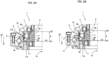
FIG. 2A is a diagram showing a state in which the externally toothed gear is separated from a friction plate during reduced-speed operation of the strain wave gearing; and -
FIG. 2B is a diagram showing a state in which the externally toothed gear contacts the friction plate during increased-speed operation of the strain wave gearing. - As shown in
FIGS. 1A and 1B , the basic configuration of thestrain wave gearing 1 is identical to that of a typical pancake-shaped or flat strain wave gearing. Thestrain wave gearing 1 comprises a first internallytoothed gear 2 and a second internallytoothed gear 3 that are coaxially aligned in the direction of anaxis 1a. The direction extending from the first internallytoothed gear 2 toward the second internallytoothed gear 3 along theaxis 1a is taken as a first direction a1, and the direction extending from the second internallytoothed gear 3 toward the first internallytoothed gear 2 along theaxis 1a is taken as a second direction a2. A cylindrical flexible externallytoothed gear 4 is coaxially disposed inside the first and second internallytoothed gears toothed gear 4 is capable of flexing in a radial direction, andexternal teeth 4a of the externallytoothed gear 4 are capable of meshing with both firstinternal teeth 2a of the first internallytoothed gear 2 and secondinternal teeth 3a of the second internallytoothed gear 3. Awave generator 5 is coaxially mounted inside the externallytoothed gear 4. Thewave generator 5 causes the externallytoothed gear 4 to flex in the radial direction and partially mesh with each of the first and second internallytoothed gears wave generator 5 is formed to have an ellipsoidal contour, thewave generator 5 causing the externallytoothed gear 4 to flex into an ellipsoidal shape and causing theexternal teeth 4a of the externallytoothed gear 4 that are positioned at both end portions on a long axis Lmax of the ellipsoidal shape to mesh with each of the firstinternal teeth 2a of the first internallytoothed gear 2 and the secondinternal teeth 3a of the second internallytoothed gear 3. - The first internally
toothed gear 2 is a fixed-side (or stationary-side) internally toothed gear, the first internallytoothed gear 2 being fixed to a fixed-side member (not shown) of a device housing or the like. The first internallytoothed gear 2 has a different number of teeth than the externallytoothed gear 4. In the present example, the first internallytoothed gear 2 has at least 2n more teeth than the externally toothed gear 4 (where n is a positive integer), ordinarily two more. In contrast, the second internallytoothed gear 3 is a reduced-rotation-output-side (drive-side) internally toothed gear, the second internallytoothed gear 3 having the same number of teeth as the externallytoothed gear 4. - The fixed-side first internally
toothed gear 2 and the output-side second internallytoothed gear 3 are supported by a main bearing 6 (a cross roller bearing) in a manner that allows relative rotation. The main bearing 6 is an outer-race separated-type bearing provided with separated outer-race elements inner race 6c, and a plurality ofrollers 6d that are mounted between the separated outer-race elements and the inner race. The separated outer-race element 6a positioned on the side of the first internallytoothed gear 2 is formed integrally with the first internallytoothed gear 2, and theinner race 6c is formed integrally with the second internallytoothed gear 3. Furthermore, anannular end plate 7 is also formed integrally with the first internallytoothed gear 2. An annular reduced-rotation output shaft 8 is formed integrally with the second internallytoothed gear 3 together with theinner race 6c. - The
wave generator 5 is provided with a hollowrotating shaft part 5a to which rotation is inputted from a motor or the like, an ellipsoidally contouredwave generator plug 5b that is formed integrally with the outer peripheral surface of therotating shaft part 5a, and a wave generator bearing 5d that is mounted on an ellipsoidal outerperipheral surface 5c of thewave generator plug 5b. A shaft end section of therotating shaft part 5a on the side of the second direction a2 is rotatably supported by theend plate 7 via abearing 9. The opposite-side shaft end section of therotating shaft part 5a is rotatably supported by theoutput shaft 8 via abearing 10. - In the present example, an end surface of the externally
toothed gear 4 on the side of the second direction a2 is referred to as an input-side end surface 4b, and an end surface of the externallytoothed gear 4 on the side of the first direction a1 is referred to as an output-side end surface 4c. The input-side end surface 4b of the externallytoothed gear 4 faces an annular inner-side end surface 7a of theend plate 7 across a prescribed space. The inner-side end surface 7a is orthogonal to theaxis 1a. In contrast, the output-side end surface 4c of the externallytoothed gear 4 faces afriction surface 11a of a friction plate 11 (friction member) across a prescribed space, thefriction plate 11 being formed integrally with therotating shaft part 5a of thewave generator 5. - A permitted movable range of the externally
toothed gear 4 in the direction of theaxis 1a is referred to as a movable range S. If the externallytoothed gear 4 were to move beyond the movable range S, a suitable meshing state with the first and second internallytoothed gears toothed gear 4 is located at a neutral position S0, which is an intermediate position between the first and second positions S1, S2. The neutral position S0 is ordinarily the support center (ball center) of thewave generator bearing 5d. Thefriction surface 11a of thefriction plate 11 is disposed at a position S3 that is closer to the neutral position s0 than is the first position S1. In contrast, the inner-side end surface 7a of theend plate 7 is disposed at the second position S2. - The
friction plate 11 is a disc-shaped plate that extends radially outward from the outer peripheral surface of therotating shaft part 5a. Thefriction surface 11a, which is formed on one end surface of thefriction plate 11, is large enough to encompass the output-side end surface 4c of the externallytoothed gear 4. Specifically, the outside diameter of thefriction surface 11a is equal to or greater than the outside diameter of the long axis Lmax of the output-side end surface 4c of the ellipsoidally flexed externallytoothed gear 4, and the inside diameter of thefriction surface 11a is equal to or less than the inside diameter of a short axis Lmin of the output-side end surface 4c. The material of thefriction plate 11 depends on the material of the externally toothed gear 4 (steel, stainless steel, an aluminum alloy, plastic, or the like) and is selected in consideration of wear, heat dissipation, strength, and other properties. Thefriction surface 11a may also be subjected to a variety of surface reformation processes. - In the present example, the
friction plate 11 is formed integrally with therotating shaft part 5a of thewave generator 5, thefriction plate 11 being configured so as to rotate integrally with therotating shaft part 5a and so as not to move relative to therotating shaft part 5a in the direction of theaxis 1a. Thefriction plate 11 may instead be formed as a component that is separate from therotating shaft part 5a of thewave generator 5 and be attached to therotating shaft part 5a or to thewave generator plug 5b so as to rotate integrally therewith and so as not to move relative thereto in the direction of theaxis 1a. -
FIGS. 2A and 2B illustrate movement of the externallytoothed gear 4 in the direction of theaxis 1a during a reduction in speed and an increase in speed of thestrain wave gearing 1. - During reduced-speed operation, in which rotation is inputted from a motor or the like to the
wave generator 5, greatly reduced rotation is generated in the externallytoothed gear 4 in accordance with the difference between the number of teeth of the fixed-side first internallytoothed gear 2 and that of the externallytoothed gear 4. As shown inFIG. 2A , during reduced-speed operation, thrust F2 acts on the externallytoothed gear 4 toward the second direction a2 (toward the reduced-rotation input side) along theaxis 1a, as indicated by the arrow, and the externallytoothed gear 4 moves in the second direction a2. Movement of the externallytoothed gear 4 is limited due to the input-side end surface 4b of the externallytoothed gear 4 coming into contact with the inner-side end surface 7a of theend plate 7. The inner-side end surface 7a differs from thefriction surface 11a of thefriction plate 11 by being, inter alia, a smooth surface having low frictional resistance. Friction loss originating from contact between the externallytoothed gear 4 and the inner-side end surface 7a can substantially be disregarded. The output-side end surface 4c at the other end of the externallytoothed gear 4 moves in a direction away from thefriction surface 11a of thefriction plate 11, and a gap between the output-side end surface 4c and thefriction surface 11a increases in size. The externallytoothed gear 4 does not come into frictional contact with thefriction plate 11, and no friction loss occurs. - In contrast, during increased-speed operation, rotation is inputted from the output-
shaft 8 side, and increased rotation is outputted from thewave generator 5. During increased-speed operation, thrust F1 acts on the externallytoothed gear 4 toward the first direction a1 (toward the reduced-rotation output side) along theaxis 1a, as indicated by the arrow inFIG. 2B , and the externallytoothed gear 4 moves in the first direction a1. The output-side end surface 4c of the externallytoothed gear 4 comes into contact with thefriction surface 11a of thefriction plate 11 before reaching the second position S2 at the end of the movable range S. Movement of the externallytoothed gear 4 is limited, and the externallytoothed gear 4 assumes a state of being pressed against thefriction surface 11a. Friction loss occurring due to sliding friction between the externallytoothed gear 4 and thefriction plate 11 makes it possible to lower the torque transmission efficiency during an increase in speed. The input-side end surface 4b at the other end of the externallytoothed gear 4 is separated from the inner-side end surface 7a of theend plate 7. - As a result of friction loss caused by the output-
side end surface 4c of the externallytoothed gear 4 contacting thefriction plate 11, which is integrated with therotating shaft part 5a of thewave generator 5, due to the thrust F1 during increased-speed operation, the torque transmission efficiency decreases only during an increase in speed. This makes it possible to reduce the input-side retention torque even if high load torque is applied from the output side. Specifically, it is possible to lower the input-side retention torque that is required in order for thewave generator 5, or a motor shaft or other input-side rotating shaft linked to thewave generator 5, to be retained so as not to rotate due to output-side torque (load-side torque).
Claims (5)
- A strain wave gearing comprising:a first internally toothed gear and a second internally toothed gear that have differing numbers of teeth;a flexible externally toothed gear that is capable of meshing with the first and second internally toothed gears and has the same number of teeth as the second internally toothed gear; anda wave generator that causes the externally toothed gear to flex into a non-circular shape and partially mesh with each of the first and second internally toothed gears,whereinthe strain wave gearing has a friction member provided with a friction surface that is disposed at a position with which the externally toothed gear can come into contact when moving in a first direction, where the first direction is a direction extending from a side of the first internally toothed gear toward a side of the second internally toothed gear along an axis; andthe friction member is attached to a rotating shaft part of the wave generator or is formed integrally with the rotating shaft part so as to rotate integrally with the rotating shaft part and so as not to move relative to the rotating shaft part in the direction of the axis.
- The strain wave gearing according to claim 1, whereinthe wave generator is provided witha wave generator plug that is provided with a non-circular outer peripheral surface, anda wave generator bearing that is mounted on the non-circular outer peripheral surface; andthe rotating shaft part and the friction member are formed integrally with the wave generator plug.
- The strain wave gearing according to claim 1, whereinthe wave generator causes the externally toothed gear to flex into an ellipsoidal shape and mesh with the first and second internally toothed gears;the friction surface of the friction member is an annular end surface; andan outside diameter of the friction surface is equal to or greater than a long-axis outside diameter of an end surface of the ellipsoidally flexed externally toothed gear, the end surface being located on a side that comes into contact with the friction surface, and an inside diameter of the friction surface is equal to or less than a short-axis inside diameter of the end surface.
- The strain wave gearing according to claim 1, further comprising:a restricting member provided with a contact surface that is disposed at a position with which the externally toothed gear can come into contact when moving in a second direction,where the second direction is a direction extending from the side of the second internally toothed gear toward the side of the first internally toothed gear along the axis.
- The strain wave gearing according to claim 4, whereinthe friction surface is disposed between a first position and a neutral position, and the contact surface is disposed at a second position,where the first position is a first-direction position for restricting a permitted movable range of the externally toothed gear in the direction of the axis, the second position is a second-direction position for the same, and the neutral position is an intermediate position between the first and second positions.
Applications Claiming Priority (1)
| Application Number | Priority Date | Filing Date | Title |
|---|---|---|---|
| PCT/JP2021/031054 WO2023026377A1 (en) | 2021-08-24 | 2021-08-24 | Strain wave gear device |
Publications (2)
| Publication Number | Publication Date |
|---|---|
| EP4394207A1 true EP4394207A1 (en) | 2024-07-03 |
| EP4394207A4 EP4394207A4 (en) | 2025-05-07 |
Family
ID=85321883
Family Applications (1)
| Application Number | Title | Priority Date | Filing Date |
|---|---|---|---|
| EP21954991.2A Pending EP4394207A4 (en) | 2021-08-24 | 2021-08-24 | Stress wave transmission device |
Country Status (6)
| Country | Link |
|---|---|
| US (1) | US12222028B2 (en) |
| EP (1) | EP4394207A4 (en) |
| JP (1) | JP7520475B2 (en) |
| KR (1) | KR20240021957A (en) |
| CN (1) | CN117836539A (en) |
| WO (1) | WO2023026377A1 (en) |
Family Cites Families (6)
| Publication number | Priority date | Publication date | Assignee | Title |
|---|---|---|---|---|
| JP4646233B2 (en) | 2006-02-28 | 2011-03-09 | 株式会社ハーモニック・ドライブ・システムズ | Method for reducing holding torque of input side of wave gear device and rotary actuator |
| DE112015000197T5 (en) | 2015-05-29 | 2017-02-16 | Harmonic Drive Systems Inc. | Flat deformation wave gear |
| DE102015113155B4 (en) * | 2015-08-10 | 2017-04-13 | Ovalo Gmbh | Tension shaft gear |
| JP6871818B2 (en) * | 2017-07-20 | 2021-05-12 | 住友重機械工業株式会社 | Flexible meshing gear device |
| JP6909141B2 (en) | 2017-12-13 | 2021-07-28 | 住友重機械工業株式会社 | Flexible meshing gear device |
| WO2023026488A1 (en) * | 2021-08-27 | 2023-03-02 | 株式会社ハーモニック・ドライブ・システムズ | Strain wave gear device and actuator |
-
2021
- 2021-08-24 CN CN202180101338.4A patent/CN117836539A/en active Pending
- 2021-08-24 EP EP21954991.2A patent/EP4394207A4/en active Pending
- 2021-08-24 JP JP2023543535A patent/JP7520475B2/en active Active
- 2021-08-24 WO PCT/JP2021/031054 patent/WO2023026377A1/en not_active Ceased
- 2021-08-24 US US18/573,062 patent/US12222028B2/en active Active
- 2021-08-24 KR KR1020247001678A patent/KR20240021957A/en active Pending
Also Published As
| Publication number | Publication date |
|---|---|
| JPWO2023026377A1 (en) | 2023-03-02 |
| JP7520475B2 (en) | 2024-07-23 |
| WO2023026377A1 (en) | 2023-03-02 |
| US20240376972A1 (en) | 2024-11-14 |
| CN117836539A (en) | 2024-04-05 |
| US12222028B2 (en) | 2025-02-11 |
| EP4394207A4 (en) | 2025-05-07 |
| TW202311646A (en) | 2023-03-16 |
| KR20240021957A (en) | 2024-02-19 |
Similar Documents
| Publication | Publication Date | Title |
|---|---|---|
| EP3388713B1 (en) | Flat strain wave gearing device | |
| US20160178044A1 (en) | Strain wave gearing device | |
| US11473653B2 (en) | Fixed ratio traction or friction drive | |
| KR101007069B1 (en) | Gear box with two-speed planetary gear system | |
| EP3702642A1 (en) | Wave generator and wave gear device | |
| US12326186B2 (en) | Strain wave gearing and actuator | |
| CN117685342A (en) | Transmission mechanism | |
| US12222028B2 (en) | Strain wave gearing | |
| US11440181B2 (en) | Planetary gear train, gearbox and industrial robot | |
| WO2018096939A1 (en) | Electric actuator | |
| TWI920346B (en) | Strain wave gearing | |
| CN111212993A (en) | transmission | |
| JP5130194B2 (en) | Power transmission device | |
| EP4636280A1 (en) | Toroidal continuously variable transmission | |
| JP4890905B2 (en) | Actuator for continuously variable transmission | |
| JP2002054705A (en) | Continuously variable transmission | |
| JP2008069928A (en) | Friction transmission | |
| JP2024101255A (en) | Planetary gear mechanism | |
| WO2019119288A1 (en) | Frictional cycloidal drive | |
| JP2015124817A (en) | Belt-type stepless transmission | |
| JP2005042874A (en) | Internal gear mechanism | |
| JP2007247851A (en) | Continuously variable transmission | |
| JP2007255595A (en) | Continuously variable transmission device | |
| JP2008064122A (en) | Continuously variable transmission | |
| JP2005233276A (en) | Traction drive type continuously variable transmission |
Legal Events
| Date | Code | Title | Description |
|---|---|---|---|
| STAA | Information on the status of an ep patent application or granted ep patent |
Free format text: STATUS: THE INTERNATIONAL PUBLICATION HAS BEEN MADE |
|
| PUAI | Public reference made under article 153(3) epc to a published international application that has entered the european phase |
Free format text: ORIGINAL CODE: 0009012 |
|
| STAA | Information on the status of an ep patent application or granted ep patent |
Free format text: STATUS: REQUEST FOR EXAMINATION WAS MADE |
|
| 17P | Request for examination filed |
Effective date: 20231228 |
|
| AK | Designated contracting states |
Kind code of ref document: A1 Designated state(s): AL AT BE BG CH CY CZ DE DK EE ES FI FR GB GR HR HU IE IS IT LI LT LU LV MC MK MT NL NO PL PT RO RS SE SI SK SM TR |
|
| DAV | Request for validation of the european patent (deleted) | ||
| DAX | Request for extension of the european patent (deleted) | ||
| REG | Reference to a national code |
Ref country code: DE Ref legal event code: R079 Free format text: PREVIOUS MAIN CLASS: F16H0001320000 Ipc: F16H0049000000 |
|
| A4 | Supplementary search report drawn up and despatched |
Effective date: 20250404 |
|
| RIC1 | Information provided on ipc code assigned before grant |
Ipc: F16H 49/00 20060101AFI20250331BHEP |