EP4394199A1 - Retaining ring, electric machine and vehicle - Google Patents
Retaining ring, electric machine and vehicle Download PDFInfo
- Publication number
- EP4394199A1 EP4394199A1 EP23212905.6A EP23212905A EP4394199A1 EP 4394199 A1 EP4394199 A1 EP 4394199A1 EP 23212905 A EP23212905 A EP 23212905A EP 4394199 A1 EP4394199 A1 EP 4394199A1
- Authority
- EP
- European Patent Office
- Prior art keywords
- retaining ring
- reinforcing portion
- present disclosure
- opening
- center
- Prior art date
- Legal status (The legal status is an assumption and is not a legal conclusion. Google has not performed a legal analysis and makes no representation as to the accuracy of the status listed.)
- Pending
Links
- 230000003014 reinforcing effect Effects 0.000 claims abstract description 51
- 230000007423 decrease Effects 0.000 claims description 5
- 230000005484 gravity Effects 0.000 description 3
- 230000004048 modification Effects 0.000 description 3
- 238000012986 modification Methods 0.000 description 3
- 230000008859 change Effects 0.000 description 2
- 238000006073 displacement reaction Methods 0.000 description 2
- 230000000694 effects Effects 0.000 description 2
- 230000002787 reinforcement Effects 0.000 description 2
- 230000007704 transition Effects 0.000 description 2
- UFHFLCQGNIYNRP-UHFFFAOYSA-N Hydrogen Chemical compound [H][H] UFHFLCQGNIYNRP-UHFFFAOYSA-N 0.000 description 1
- 230000002411 adverse Effects 0.000 description 1
- 230000003247 decreasing effect Effects 0.000 description 1
- 239000000446 fuel Substances 0.000 description 1
- 229910052739 hydrogen Inorganic materials 0.000 description 1
- 239000001257 hydrogen Substances 0.000 description 1
- 238000000034 method Methods 0.000 description 1
- 230000008569 process Effects 0.000 description 1
- 230000004044 response Effects 0.000 description 1
Images



Classifications
-
- F—MECHANICAL ENGINEERING; LIGHTING; HEATING; WEAPONS; BLASTING
- F16—ENGINEERING ELEMENTS AND UNITS; GENERAL MEASURES FOR PRODUCING AND MAINTAINING EFFECTIVE FUNCTIONING OF MACHINES OR INSTALLATIONS; THERMAL INSULATION IN GENERAL
- F16C—SHAFTS; FLEXIBLE SHAFTS; ELEMENTS OR CRANKSHAFT MECHANISMS; ROTARY BODIES OTHER THAN GEARING ELEMENTS; BEARINGS
- F16C35/00—Rigid support of bearing units; Housings, e.g. caps, covers
- F16C35/04—Rigid support of bearing units; Housings, e.g. caps, covers in the case of ball or roller bearings
- F16C35/06—Mounting or dismounting of ball or roller bearings; Fixing them onto shaft or in housing
- F16C35/067—Fixing them in a housing
-
- H—ELECTRICITY
- H02—GENERATION; CONVERSION OR DISTRIBUTION OF ELECTRIC POWER
- H02K—DYNAMO-ELECTRIC MACHINES
- H02K7/00—Arrangements for handling mechanical energy structurally associated with dynamo-electric machines, e.g. structural association with mechanical driving motors or auxiliary dynamo-electric machines
- H02K7/04—Balancing means
-
- F—MECHANICAL ENGINEERING; LIGHTING; HEATING; WEAPONS; BLASTING
- F16—ENGINEERING ELEMENTS AND UNITS; GENERAL MEASURES FOR PRODUCING AND MAINTAINING EFFECTIVE FUNCTIONING OF MACHINES OR INSTALLATIONS; THERMAL INSULATION IN GENERAL
- F16B—DEVICES FOR FASTENING OR SECURING CONSTRUCTIONAL ELEMENTS OR MACHINE PARTS TOGETHER, e.g. NAILS, BOLTS, CIRCLIPS, CLAMPS, CLIPS OR WEDGES; JOINTS OR JOINTING
- F16B21/00—Means for preventing relative axial movement of a pin, spigot, shaft or the like and a member surrounding it; Stud-and-socket releasable fastenings
- F16B21/10—Means for preventing relative axial movement of a pin, spigot, shaft or the like and a member surrounding it; Stud-and-socket releasable fastenings by separate parts
- F16B21/16—Means for preventing relative axial movement of a pin, spigot, shaft or the like and a member surrounding it; Stud-and-socket releasable fastenings by separate parts with grooves or notches in the pin or shaft
- F16B21/18—Means for preventing relative axial movement of a pin, spigot, shaft or the like and a member surrounding it; Stud-and-socket releasable fastenings by separate parts with grooves or notches in the pin or shaft with circlips or like resilient retaining devices, i.e. resilient in the plane of the ring or the like; Details
-
- F—MECHANICAL ENGINEERING; LIGHTING; HEATING; WEAPONS; BLASTING
- F16—ENGINEERING ELEMENTS AND UNITS; GENERAL MEASURES FOR PRODUCING AND MAINTAINING EFFECTIVE FUNCTIONING OF MACHINES OR INSTALLATIONS; THERMAL INSULATION IN GENERAL
- F16B—DEVICES FOR FASTENING OR SECURING CONSTRUCTIONAL ELEMENTS OR MACHINE PARTS TOGETHER, e.g. NAILS, BOLTS, CIRCLIPS, CLAMPS, CLIPS OR WEDGES; JOINTS OR JOINTING
- F16B21/00—Means for preventing relative axial movement of a pin, spigot, shaft or the like and a member surrounding it; Stud-and-socket releasable fastenings
- F16B21/10—Means for preventing relative axial movement of a pin, spigot, shaft or the like and a member surrounding it; Stud-and-socket releasable fastenings by separate parts
- F16B21/16—Means for preventing relative axial movement of a pin, spigot, shaft or the like and a member surrounding it; Stud-and-socket releasable fastenings by separate parts with grooves or notches in the pin or shaft
- F16B21/18—Means for preventing relative axial movement of a pin, spigot, shaft or the like and a member surrounding it; Stud-and-socket releasable fastenings by separate parts with grooves or notches in the pin or shaft with circlips or like resilient retaining devices, i.e. resilient in the plane of the ring or the like; Details
- F16B21/183—Means for preventing relative axial movement of a pin, spigot, shaft or the like and a member surrounding it; Stud-and-socket releasable fastenings by separate parts with grooves or notches in the pin or shaft with circlips or like resilient retaining devices, i.e. resilient in the plane of the ring or the like; Details internal, i.e. with spreading action
-
- F—MECHANICAL ENGINEERING; LIGHTING; HEATING; WEAPONS; BLASTING
- F16—ENGINEERING ELEMENTS AND UNITS; GENERAL MEASURES FOR PRODUCING AND MAINTAINING EFFECTIVE FUNCTIONING OF MACHINES OR INSTALLATIONS; THERMAL INSULATION IN GENERAL
- F16B—DEVICES FOR FASTENING OR SECURING CONSTRUCTIONAL ELEMENTS OR MACHINE PARTS TOGETHER, e.g. NAILS, BOLTS, CIRCLIPS, CLAMPS, CLIPS OR WEDGES; JOINTS OR JOINTING
- F16B21/00—Means for preventing relative axial movement of a pin, spigot, shaft or the like and a member surrounding it; Stud-and-socket releasable fastenings
- F16B21/10—Means for preventing relative axial movement of a pin, spigot, shaft or the like and a member surrounding it; Stud-and-socket releasable fastenings by separate parts
- F16B21/16—Means for preventing relative axial movement of a pin, spigot, shaft or the like and a member surrounding it; Stud-and-socket releasable fastenings by separate parts with grooves or notches in the pin or shaft
- F16B21/18—Means for preventing relative axial movement of a pin, spigot, shaft or the like and a member surrounding it; Stud-and-socket releasable fastenings by separate parts with grooves or notches in the pin or shaft with circlips or like resilient retaining devices, i.e. resilient in the plane of the ring or the like; Details
- F16B21/186—Means for preventing relative axial movement of a pin, spigot, shaft or the like and a member surrounding it; Stud-and-socket releasable fastenings by separate parts with grooves or notches in the pin or shaft with circlips or like resilient retaining devices, i.e. resilient in the plane of the ring or the like; Details external, i.e. with contracting action
-
- F—MECHANICAL ENGINEERING; LIGHTING; HEATING; WEAPONS; BLASTING
- F16—ENGINEERING ELEMENTS AND UNITS; GENERAL MEASURES FOR PRODUCING AND MAINTAINING EFFECTIVE FUNCTIONING OF MACHINES OR INSTALLATIONS; THERMAL INSULATION IN GENERAL
- F16C—SHAFTS; FLEXIBLE SHAFTS; ELEMENTS OR CRANKSHAFT MECHANISMS; ROTARY BODIES OTHER THAN GEARING ELEMENTS; BEARINGS
- F16C35/00—Rigid support of bearing units; Housings, e.g. caps, covers
- F16C35/04—Rigid support of bearing units; Housings, e.g. caps, covers in the case of ball or roller bearings
- F16C35/06—Mounting or dismounting of ball or roller bearings; Fixing them onto shaft or in housing
- F16C35/07—Fixing them on the shaft or housing with interposition of an element
- F16C35/073—Fixing them on the shaft or housing with interposition of an element between shaft and inner race ring
-
- F—MECHANICAL ENGINEERING; LIGHTING; HEATING; WEAPONS; BLASTING
- F16—ENGINEERING ELEMENTS AND UNITS; GENERAL MEASURES FOR PRODUCING AND MAINTAINING EFFECTIVE FUNCTIONING OF MACHINES OR INSTALLATIONS; THERMAL INSULATION IN GENERAL
- F16C—SHAFTS; FLEXIBLE SHAFTS; ELEMENTS OR CRANKSHAFT MECHANISMS; ROTARY BODIES OTHER THAN GEARING ELEMENTS; BEARINGS
- F16C35/00—Rigid support of bearing units; Housings, e.g. caps, covers
- F16C35/04—Rigid support of bearing units; Housings, e.g. caps, covers in the case of ball or roller bearings
- F16C35/06—Mounting or dismounting of ball or roller bearings; Fixing them onto shaft or in housing
- F16C35/07—Fixing them on the shaft or housing with interposition of an element
- F16C35/077—Fixing them on the shaft or housing with interposition of an element between housing and outer race ring
-
- H—ELECTRICITY
- H02—GENERATION; CONVERSION OR DISTRIBUTION OF ELECTRIC POWER
- H02K—DYNAMO-ELECTRIC MACHINES
- H02K1/00—Details of the magnetic circuit
- H02K1/06—Details of the magnetic circuit characterised by the shape, form or construction
- H02K1/22—Rotating parts of the magnetic circuit
- H02K1/28—Means for mounting or fastening rotating magnetic parts on to, or to, the rotor structures
-
- F—MECHANICAL ENGINEERING; LIGHTING; HEATING; WEAPONS; BLASTING
- F16—ENGINEERING ELEMENTS AND UNITS; GENERAL MEASURES FOR PRODUCING AND MAINTAINING EFFECTIVE FUNCTIONING OF MACHINES OR INSTALLATIONS; THERMAL INSULATION IN GENERAL
- F16C—SHAFTS; FLEXIBLE SHAFTS; ELEMENTS OR CRANKSHAFT MECHANISMS; ROTARY BODIES OTHER THAN GEARING ELEMENTS; BEARINGS
- F16C19/00—Bearings with rolling contact, for exclusively rotary movement
- F16C19/02—Bearings with rolling contact, for exclusively rotary movement with bearing balls essentially of the same size in one or more circular rows
- F16C19/04—Bearings with rolling contact, for exclusively rotary movement with bearing balls essentially of the same size in one or more circular rows for radial load mainly
- F16C19/06—Bearings with rolling contact, for exclusively rotary movement with bearing balls essentially of the same size in one or more circular rows for radial load mainly with a single row or balls
-
- F—MECHANICAL ENGINEERING; LIGHTING; HEATING; WEAPONS; BLASTING
- F16—ENGINEERING ELEMENTS AND UNITS; GENERAL MEASURES FOR PRODUCING AND MAINTAINING EFFECTIVE FUNCTIONING OF MACHINES OR INSTALLATIONS; THERMAL INSULATION IN GENERAL
- F16C—SHAFTS; FLEXIBLE SHAFTS; ELEMENTS OR CRANKSHAFT MECHANISMS; ROTARY BODIES OTHER THAN GEARING ELEMENTS; BEARINGS
- F16C2326/00—Articles relating to transporting
- F16C2326/01—Parts of vehicles in general
-
- F—MECHANICAL ENGINEERING; LIGHTING; HEATING; WEAPONS; BLASTING
- F16—ENGINEERING ELEMENTS AND UNITS; GENERAL MEASURES FOR PRODUCING AND MAINTAINING EFFECTIVE FUNCTIONING OF MACHINES OR INSTALLATIONS; THERMAL INSULATION IN GENERAL
- F16C—SHAFTS; FLEXIBLE SHAFTS; ELEMENTS OR CRANKSHAFT MECHANISMS; ROTARY BODIES OTHER THAN GEARING ELEMENTS; BEARINGS
- F16C2380/00—Electrical apparatus
- F16C2380/26—Dynamo-electric machines or combinations therewith, e.g. electro-motors and generators
Definitions
- the rotor rotates, and the retaining ring rotates with the rotor shaft of the rotor.
- the centrifugal force produced by this rotation tends to cause the opening of the retaining ring to open.
- the rotation speed of the electric machine reaches a rotation speed threshold that the retaining ring can sustain, the centrifugal force produced by the rotation of the retaining ring is sufficient to make the opening of the retaining ring open to the extent that the retaining ring can detach from the rotor shaft, so that the rotation speed of the electric machine cannot be further increased.
- the balance hole is an oblong hole.
- the width of the oblong hole is relatively small for the same area, which reduces the negative impact on the reinforcement effect of the reinforcing portion.
- the present disclosure further relates to an electric machine comprising the retaining ring described above, and the retaining ring is used to constrain an axial position of a bearing on a rotor of the electric machine.
- the increased width of the reinforcing portion 6 at its center 61 is roughly equivalent to the width of other parts of the annular body 2, i.e., the maximum width at the reinforcing portion 6 is approximately twice the width of other parts of the annular body 2.
Landscapes
- Engineering & Computer Science (AREA)
- General Engineering & Computer Science (AREA)
- Mechanical Engineering (AREA)
- Power Engineering (AREA)
- Rolling Contact Bearings (AREA)
- Motor Or Generator Frames (AREA)
Abstract
The present disclosure relates to a retaining ring (1), including: an annular body (2) including an opening (3); an operating part (4) arranged at two sides of the opening, and including operating holes (5) arranged at two sides of the opening (3). The annular body (2) further includes a reinforcing portion (6) arranged opposite the opening (3). The present disclosure further relates to an electric machine including the retaining ring and a vehicle including the electric machine.
Description
- The present disclosure relates to a retaining ring. In particular, an annular body of the retaining ring comprises a reinforcing portion to increase its strength and adapt to high rotation speed applications. The present disclosure further relates to an electric machine comprising the retaining ring and a vehicle comprising the electric machine.
- In an electric machine of a vehicle, the rotor shaft of the rotor is fitted with one or more components, such as a rotor core, end plates, and bearings for rotationally supporting the rotor shaft, etc. A protrusion may be provided at one end of the rotor shaft of the rotor to constrain the axial position of components set thereon, while at the opposite end thereof, a protrusion is inconveniently provided due to the need for assembly. In order to constrain the axial position of the components at this end, it is known to install an additional retaining ring at this end of the rotor shaft.
- The retaining ring is an annular member comprising an opening, and its inner diameter is smaller than the diameter of the rotor shaft. The retaining ring may be opened, placed and clamped onto a pre-machined groove on the rotor shaft using tools such as callipers. After being opened, the size of the opening of the retaining ring is larger than the diameter of the groove, so the retaining ring can be removed from the groove or reinstalled in the groove.
- When the electric machine is operating, the rotor rotates, and the retaining ring rotates with the rotor shaft of the rotor. The centrifugal force produced by this rotation tends to cause the opening of the retaining ring to open. When the rotation speed of the electric machine reaches a rotation speed threshold that the retaining ring can sustain, the centrifugal force produced by the rotation of the retaining ring is sufficient to make the opening of the retaining ring open to the extent that the retaining ring can detach from the rotor shaft, so that the rotation speed of the electric machine cannot be further increased.
- Therefore, a retaining ring is needed that can reduce the extent to which the opening expands at high rotation speeds and is thus difficult to detach from the shaft, so as to increase the rotation speed threshold and adapt to high rotation speed applications.
- In response to the problems and demands mentioned above, the present disclosure proposes a new type of retaining ring, which solves the above problems and brings about other technical effects by adopting the following technical features.
- The retaining ring according to the present disclosure comprises: an annular body comprising an opening; an operating part arranged at two sides of the opening, and comprising operating holes arranged at two sides of the opening. The annular body further comprises a reinforcing portion arranged opposite the opening.
- One of the objects of the present disclosure is to provide a retaining ring in which it is possible to reduce the extent to which the opening expands at high rotation speeds, making it difficult to detach from the shaft, increasing the rotation speed threshold, and adapting to high rotation speed applications. The retaining ring according to the present disclosure comprises a reinforcing portion on the annular body arranged opposite the opening of the retaining ring. Such a reinforcing portion increases the strength of the retaining ring, enabling it to resist centrifugal force with relatively small deformation, and the opening degree becomes smaller. Therefore, the rotation speed threshold for detachment of the retaining ring from the shaft is increased and adapted to high rotation speed applications. The inventors of the present disclosure have discovered that, compared with a conventional retaining ring without a reinforcing portion, the rotation speed threshold that the retaining ring according to the present disclosure can sustain can be increased from about 17000 RPM to over 20000 RPM.
- The retaining ring according to the present disclosure may also comprise one or more of the following features individually or in combination.
- According to one embodiment of the present disclosure, the retaining ring further comprises a balance hole arranged on the reinforcing portion. The reinforcing portion on the retaining ring increases the strength of the retaining ring, but also cause the gravity center of the retaining ring to shift, and the retaining ring is no longer balanced. In this way, after assembly, the gravity center of the retaining ring will shift from the center of the shaft, resulting in imbalance during rotation process. By arranging a balance hole on the reinforcing portion, the deviation of the gravity center caused by the reinforcing portion is counteracted, and the retaining ring restores balance.
- According to one embodiment of the present disclosure, the balance hole is symmetrical with respect to a diameter (D) passing through the center of the reinforcing portion.
- According to one embodiment of the present disclosure, the retaining ring comprises multiple balance holes, and the multiple balance holes are symmetrical with respect to a diameter (D) passing through the center of the reinforcing portion.
- According to the above features, the balance hole is only used to eliminate the imbalance of the reinforcing portion, and will not cause the imbalance of the retaining ring itself.
- According to one embodiment of the present disclosure, the balance hole is an oblong hole. The width of the oblong hole is relatively small for the same area, which reduces the negative impact on the reinforcement effect of the reinforcing portion.
- According to one embodiment of the present disclosure, the increased width of the reinforcing portion is variable, and/or the increased thickness of the reinforcing portion is variable.
- According to one embodiment of the present disclosure, the reinforcing portion has a maximum width at its center, and gradually decreases from its center towards two ends; and/or the reinforcing portion has a maximum thickness at its center, and gradually decreases from its center towards the two ends.
- According to the above features, the reinforcing portion has a smooth transition relative to other parts of the annular body, and is largest in size at its center opposite the opening. Such a structure increases the ability of the reinforcing portion to resist expansion of the opening.
- According to one embodiment of the present disclosure, the retaining ring is made by stamping.
- The present disclosure further relates to an electric machine comprising the retaining ring described above, and the retaining ring is used to constrain an axial position of a bearing on a rotor of the electric machine.
- The present disclosure further relates to a vehicle comprising the electric machine described above.
- The above and other features and advantages of the present disclosure will become more apparent through the following detailed description of exemplary embodiments combined with the accompanying drawings, and the description and the accompanying drawings are only for illustrative purposes and are not intended to limit the scope of the present disclosure in any way. The following accompanying drawings are not intentionally drawn in equal scaling according to actual size, and the focus is on showing the main idea of the present disclosure.
-
Fig. 1A is a cross-sectional view of a portion of the electric machine according to the present disclosure, wherein a retaining ring is installed on the rotor shaft of the rotor; -
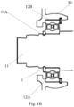
Fig. 1B is an enlarged view of the retaining ring inFig. 1A ; -
Fig. 2 is a perspective view of the retaining ring according to the present disclosure; -
Fig. 3 is a top view of the retaining ring according to the present disclosure. - In order to make the purpose, technical solution and advantages of the embodiments of the present disclosure clearer, the technical solution of the embodiments of the present disclosure will be described clearly and completely below in conjunction with the accompanying drawings of the embodiments of the present disclosure.
- Unless otherwise defined, technical terms or scientific terms used herein shall have the common meanings understood by those skilled in the art. Similar words such as "one", "a" or "the" used in the description and claims of the patent application do not indicate a quantity limit, but mean that there is at least one. Similar words such as "comprise" or "include" mean that the elements or objects appearing before the word cover the elements or objects and their equivalents listed after the word. Similar words such as "connecting" or "connection" are not limited to physical or mechanical connections, but may comprise electrical connections, whether direct or indirect. The terms "up", "down", "left", "right", etc. are only used to indicate relative positional relationships, and when the absolute position of the described object changes, the relative positional relationship may also change accordingly.
-
Fig. 1A is a cross-sectional view of a portion of anelectric machine 100 according to one embodiment of the present disclosure. Theelectric machine 100 comprises arotor 10, astator 20 and ahousing 30. Therotor shaft 11 of therotor 10 is fitted with a bearing 12. Theinner ring 12A of the bearing 12 rotates synchronously with therotor shaft 11, while itsouter ring 12B of is fixed relative to thehousing 30 and used to support therotor 10. The axial position of the bearing 12 is maintained by theretaining ring 1. Referring to the enlarged view ofFig. 1B , the retainingring 1 is clamped in agroove 11A of therotor shaft 11, and rotates synchronously with therotor shaft 11. The retainingring 1 is in contact with theinner ring 12A of the bearing 12, and thus limits the axial displacement of the bearing 12. -
Fig. 2 andFig. 3 are perspective view and top view of the retainingring 1 according to one exemplary embodiment of the present disclosure respectively. - As shown in
Fig. 2 , the retainingring 1 comprises anannular body 2 and anoperating part 4. Theannular body 2 has anopening 3. When the retainingring 1 is not operated, the inner diameter of theannular body 2 is smaller than the diameter of therotor shaft 11 but larger than the diameter of thegroove 11A, while the size of theopening 3 is smaller than the diameter of thegroove 11A, and the retainingring 1 can thus be clamped in thegroove 11A. - The operating
part 4 is arranged at two sides of theopening 3, and comprises operatingholes 5 arranged at two sides of theopening 3. The callipers for operating the retainingring 1 can be inserted into the operating holes 5 through protrusions, and apply force to expand theopening 3 to a size larger than the diameter of thegroove 11A of therotor shaft 11, so as to clamp the retainingring 1 into thegroove 11A or remove the retainingring 1 from thegroove 11A. - When the retaining
ring 1 rotates with therotor shaft 11, the produced centrifugal force will also expand theopening 3 of the retainingring 1. With the rotation speed of theelectric machine 100 increases, the centrifugal force on the retainingring 1 will also increase. When the rotation speed of the electric machine increases beyond a rotation speed threshold that the retainingring 1 can sustain, the opening degree of theopening 3 allows the retainingring 1 to detach from therotor shaft 11, and the retainingring 1 can no longer serve the function of limiting the axial displacement of the bearing 12. In one specific embodiment, this limitation limits the rotation speed of theelectric machine 100 to a maximum speed of about 17000 RPM. - In order to increase the strength of the retaining
ring 1 and increase the rotation speed threshold that it can sustain, theannular body 2 further comprises a reinforcingportion 6 arranged opposite theopening 3. Compared to the other parts of theannular body 2, the reinforcingportion 6 may comprise an increased size. For example, in the embodiment shown inFig. 3 , it is shown that the reinforcingportion 6 of the retainingring 1 has an increased width. InFig. 3 , the portion of theannular body 2 outside the curved dashed line is a width-increased portion of the reinforcingportion 6. As shown in the figure, the increased width of the reinforcingportion 6 is variable, being largest at itscenter 61, and gradually decreasing from itscenter 61 towards two ends 62. Therefore, the reinforcingportion 6 transitions smoothly to other parts of theannular body 2. The size of the reinforcingportion 6 being largest at itscenter 61 can increase its ability to resist centrifugal force. For the retainingring 1 used to constrain the axial position of the bearing on therotor 10 of theelectric machine 100, the width of the reinforcingportion 6 at itscenter 61 is constrained by the inner diameter of theouter ring 12B of the bearing 12, i.e., the contact between the reinforcingportion 6 and theouter ring 12B must be avoided. In particular, the increased width of the reinforcingportion 6 at itscenter 61 is roughly equivalent to the width of other parts of theannular body 2, i.e., the maximum width at the reinforcingportion 6 is approximately twice the width of other parts of theannular body 2. - Although not shown in the drawings, the reinforcing
portion 6 may also have different structures. For example, the reinforcingportion 6 may have an increased thickness, and this increased thickness may also be variable, such that the reinforcingportion 6 has a maximum thickness at itscenter 61, and gradually decreases from itscenter 61 towards two ends 62. It should be noted that the reinforcingportion 6 may also have a constant size with the increased width or thickness that is unchanged. - By providing the reinforcing portion, the strength of the retaining ring according to the present disclosure is increased, so that the rotation speed threshold that it can sustain is increased. In one specific embodiment, the rotation speed of the
electric machine 100 employing the retainingring 1 according to the present disclosure can reach about 20000 RPM. - The reinforcing
portion 6 of theannular body 2 increases the mass of the retainingring 1 at a top side thereof, such that the mass center of the retainingring 1 is shifted upwards from its center, so the balance of the retainingring 1 is destroyed. As the retainingring 1 rotates with therotor shaft 11, the mass center of the retaining ring will shift from its rotation axis. In order to reduce or eliminate this imbalance, the retainingring 1 is provided withbalance holes 7 at the reinforcingportion 6. - The balance holes 7 can reduce the mass of the reinforcing
portion 6, so that the mass center of the retainingring 1 remains at its center. The retainingring 1 can thus restore balance. In addition, because the balance holes 7 will not reduce the increased size of the reinforcingportion 6, they will not have a significant adverse impact on thereinforcement portion 6 in increasing the strength of the retainingring 1. - Referring to
Fig. 3 , the retainingring 1 may comprise 7balance holes 7 which are symmetrical with respect to a diameter D passing through thecenter 61 of the reinforcingportion 6. It can be understood that the number ofbalance holes 7 can change according to requirements. It is also conceivable to provide only onebalance hole 7 symmetrical with respect to the diameter D. In the embodiment shown inFig. 3 , thebalance hole 7 has the form of an oblong hole. In different embodiments, thebalance hole 7 may also have different shapes, such as a round hole, etc. In addition, thebalance hole 7 may also be a blind hole, or have the form of a recess provided at the reinforcingportion 6. - According to another aspect of the present disclosure, a vehicle is proposed which comprises the electric machine mentioned above. The vehicle may be an electrified vehicle, such as a battery electric vehicle (BEV), a hybrid electric vehicle (HEV), a plug-in hybrid electric vehicle (PHEV), a range extended EV and a fuel cell electric vehicle (FCEV). The vehicle may also be a hydrogen powered vehicle.
- Certain features, structures or characteristics in one or more embodiments of the present disclosure may be combined appropriately.
- The above is a description of the present disclosure and should not be considered as a limitation thereof. Although several exemplary embodiments of the present disclosure have been described, those skilled in the art shall easily understand that many modifications can be made to the exemplary embodiments without departing from the novel teaching and advantages of the present disclosure. Therefore, all such modifications are intended to be comprised within the scope of the present disclosure as defined by the claims. It should be understood that the above is a description of the present disclosure and that the present disclosure should not be considered as being limited to the disclosed specific embodiments, and the modifications to the disclosed embodiments and other embodiments are intended to be comprised within the scope of the present disclosure.
Claims (11)
- A retaining ring (1), comprising:an annular body (2) comprising an opening (3);an operating part (4) arranged at two sides of the opening (3), and comprising operating holes (5) arranged at two sides of the opening (3),wherein, the annular body (2) further comprises a reinforcing portion (6) arranged opposite the opening (3).
- The retaining ring (1) according to claim 1, further comprising a balance hole (7) arranged on the reinforcing portion (6).
- The retaining ring (1) according to claim 2, wherein,
the balance hole (7) is symmetrical with respect to a diameter (D) passing through a center (61) of the reinforcing portion (6). - The retaining ring (1) according to claim 2 or claim 3, wherein,
the retaining ring (1) comprises multiple balance holes (7), the multiple balance holes (7) are symmetrical with respect to a diameter (D) passing through a center (61) of the reinforcing portion (6). - The retaining ring (1) according to claim 4, wherein,
the balance hole (7) is an oblong hole. - The retaining ring (1) according to any one of claims 1 to 3, wherein,
the reinforcing portion (6) has an increased width and/or an increased thickness. - The retaining ring (1) according to claim 6, wherein,
the increased width of the reinforcing portion (6) is variable, and/or the increased thickness of the reinforcing portion (6) is variable. - The retaining ring (1) according to claim 7, wherein,the reinforcing portion (6) has a maximum width at its center (61), and gradually decreases from its center (61) towards two ends (62); and/orthe reinforcing portion (6) has a maximum thickness at its center (61), and gradually decreases from its center (61) towards the two ends (62).
- The retaining ring according to any one of claims 1 to 3, wherein,
the retaining ring (1) is made by stamping. - An electric machine, comprising the retaining ring (1) according to any one of claims 1 to 9, wherein, the retaining ring (1) is used to constrain an axial position of a bearing on a rotor of the electric machine.
- A vehicle, comprising the electric machine according to claim 10.
Applications Claiming Priority (1)
| Application Number | Priority Date | Filing Date | Title |
|---|---|---|---|
| CN202211689702.6A CN118264038A (en) | 2022-12-27 | 2022-12-27 | Retaining ring, motor and vehicle |
Publications (1)
| Publication Number | Publication Date |
|---|---|
| EP4394199A1 true EP4394199A1 (en) | 2024-07-03 |
Family
ID=89029615
Family Applications (1)
| Application Number | Title | Priority Date | Filing Date |
|---|---|---|---|
| EP23212905.6A Pending EP4394199A1 (en) | 2022-12-27 | 2023-11-29 | Retaining ring, electric machine and vehicle |
Country Status (2)
| Country | Link |
|---|---|
| EP (1) | EP4394199A1 (en) |
| CN (1) | CN118264038A (en) |
Citations (5)
| Publication number | Priority date | Publication date | Assignee | Title |
|---|---|---|---|---|
| US2416852A (en) * | 1942-12-17 | 1947-03-04 | Waldes Koh I Noer Inc | Retaining ring |
| GB1165680A (en) * | 1966-12-12 | 1969-10-01 | Eaton Yale & Towne | Split Resilient Rings for use as Locating or Retaining Members |
| JP2010038254A (en) * | 2008-08-05 | 2010-02-18 | Jtekt Corp | Mounting structure for retaining ring and steering device for vehicle |
| US20220154754A1 (en) * | 2020-10-30 | 2022-05-19 | Seeger-Orbis Gmbh | Retaining Ring |
| US20220349313A1 (en) * | 2021-04-29 | 2022-11-03 | Pratt & Whitney Canada Corp. | Internal retaining ring for a rotating assembly in a gas turbine engine |
-
2022
- 2022-12-27 CN CN202211689702.6A patent/CN118264038A/en active Pending
-
2023
- 2023-11-29 EP EP23212905.6A patent/EP4394199A1/en active Pending
Patent Citations (5)
| Publication number | Priority date | Publication date | Assignee | Title |
|---|---|---|---|---|
| US2416852A (en) * | 1942-12-17 | 1947-03-04 | Waldes Koh I Noer Inc | Retaining ring |
| GB1165680A (en) * | 1966-12-12 | 1969-10-01 | Eaton Yale & Towne | Split Resilient Rings for use as Locating or Retaining Members |
| JP2010038254A (en) * | 2008-08-05 | 2010-02-18 | Jtekt Corp | Mounting structure for retaining ring and steering device for vehicle |
| US20220154754A1 (en) * | 2020-10-30 | 2022-05-19 | Seeger-Orbis Gmbh | Retaining Ring |
| US20220349313A1 (en) * | 2021-04-29 | 2022-11-03 | Pratt & Whitney Canada Corp. | Internal retaining ring for a rotating assembly in a gas turbine engine |
Also Published As
| Publication number | Publication date |
|---|---|
| CN118264038A (en) | 2024-06-28 |
Similar Documents
| Publication | Publication Date | Title |
|---|---|---|
| EP2395631B1 (en) | Electric motor and rotor | |
| EP2782217B1 (en) | Rotor for rotating electric machine and motor for electric power steering | |
| CN103944291A (en) | Rotary electric machine | |
| JPS59194652A (en) | Rotor of permanent magnet synchronous motor | |
| CN102377306B (en) | The manufacture method of electric rotating machine, wind generator system and electric rotating machine | |
| WO2022142498A1 (en) | Disc motor | |
| EP3748820B1 (en) | Rotor for dynamo-electric machine, and dynamo-electric machine | |
| EP4394199A1 (en) | Retaining ring, electric machine and vehicle | |
| US11277053B2 (en) | Rotor, motor, and method for manufacturing rotor | |
| US20200227963A1 (en) | Rotor core of rotating electrical machine | |
| WO2022267011A1 (en) | Rotor, electric motor, powertrain and vehicle | |
| JP5495045B2 (en) | Rotating electrical machine rotor | |
| JP7554727B2 (en) | Rotor, rotating electric machine, and method for manufacturing rotor | |
| CN114483921A (en) | Electrically-driven gearbox assembly for positioning stepped hole | |
| US7911095B2 (en) | Servo motor with large rotor inertia | |
| CN108471189A (en) | Motor and its manufacturing method | |
| CN219760737U (en) | Rotor core mounting structure, motor, automobile power system and automobile | |
| CN214626674U (en) | Motor and compressor with same | |
| CN112106280A (en) | Motor, power device, movable platform and motor installation method | |
| CN113098166B (en) | Rotor punching sheet and rotor iron core | |
| WO2023246014A1 (en) | Motor outer rotor structure, rotary power unit, and quadruped robot | |
| JP2005176530A (en) | Rotation balance correction structure of permanent magnet type rotating electrical machine | |
| JP2009124881A (en) | Rotating electric machine | |
| US20250379484A1 (en) | Motor shell, manufacturing method of motor shell, and electric fan | |
| CN218335468U (en) | Rotor assembly, rotor and motor |
Legal Events
| Date | Code | Title | Description |
|---|---|---|---|
| PUAI | Public reference made under article 153(3) epc to a published international application that has entered the european phase |
Free format text: ORIGINAL CODE: 0009012 |
|
| STAA | Information on the status of an ep patent application or granted ep patent |
Free format text: STATUS: REQUEST FOR EXAMINATION WAS MADE |
|
| 17P | Request for examination filed |
Effective date: 20231129 |
|
| AK | Designated contracting states |
Kind code of ref document: A1 Designated state(s): AL AT BE BG CH CY CZ DE DK EE ES FI FR GB GR HR HU IE IS IT LI LT LU LV MC ME MK MT NL NO PL PT RO RS SE SI SK SM TR |