EP4394195A1 - Sliding structure - Google Patents
Sliding structure Download PDFInfo
- Publication number
- EP4394195A1 EP4394195A1 EP22861343.6A EP22861343A EP4394195A1 EP 4394195 A1 EP4394195 A1 EP 4394195A1 EP 22861343 A EP22861343 A EP 22861343A EP 4394195 A1 EP4394195 A1 EP 4394195A1
- Authority
- EP
- European Patent Office
- Prior art keywords
- sliding
- hard layer
- base member
- layer
- sliding element
- Prior art date
- Legal status (The legal status is an assumption and is not a legal conclusion. Google has not performed a legal analysis and makes no representation as to the accuracy of the status listed.)
- Pending
Links
Images


Classifications
-
- F—MECHANICAL ENGINEERING; LIGHTING; HEATING; WEAPONS; BLASTING
- F16—ENGINEERING ELEMENTS AND UNITS; GENERAL MEASURES FOR PRODUCING AND MAINTAINING EFFECTIVE FUNCTIONING OF MACHINES OR INSTALLATIONS; THERMAL INSULATION IN GENERAL
- F16C—SHAFTS; FLEXIBLE SHAFTS; ELEMENTS OR CRANKSHAFT MECHANISMS; ROTARY BODIES OTHER THAN GEARING ELEMENTS; BEARINGS
- F16C17/00—Sliding-contact bearings for exclusively rotary movement
- F16C17/12—Sliding-contact bearings for exclusively rotary movement characterised by features not related to the direction of the load
- F16C17/14—Sliding-contact bearings for exclusively rotary movement characterised by features not related to the direction of the load specially adapted for operating in water
-
- F—MECHANICAL ENGINEERING; LIGHTING; HEATING; WEAPONS; BLASTING
- F16—ENGINEERING ELEMENTS AND UNITS; GENERAL MEASURES FOR PRODUCING AND MAINTAINING EFFECTIVE FUNCTIONING OF MACHINES OR INSTALLATIONS; THERMAL INSULATION IN GENERAL
- F16C—SHAFTS; FLEXIBLE SHAFTS; ELEMENTS OR CRANKSHAFT MECHANISMS; ROTARY BODIES OTHER THAN GEARING ELEMENTS; BEARINGS
- F16C33/00—Parts of bearings; Special methods for making bearings or parts thereof
- F16C33/02—Parts of sliding-contact bearings
- F16C33/04—Brasses; Bushes; Linings
- F16C33/06—Sliding surface mainly made of metal
- F16C33/12—Structural composition; Use of special materials or surface treatments, e.g. for rust-proofing
- F16C33/122—Multilayer structures of sleeves, washers or liners
-
- F—MECHANICAL ENGINEERING; LIGHTING; HEATING; WEAPONS; BLASTING
- F16—ENGINEERING ELEMENTS AND UNITS; GENERAL MEASURES FOR PRODUCING AND MAINTAINING EFFECTIVE FUNCTIONING OF MACHINES OR INSTALLATIONS; THERMAL INSULATION IN GENERAL
- F16C—SHAFTS; FLEXIBLE SHAFTS; ELEMENTS OR CRANKSHAFT MECHANISMS; ROTARY BODIES OTHER THAN GEARING ELEMENTS; BEARINGS
- F16C33/00—Parts of bearings; Special methods for making bearings or parts thereof
- F16C33/02—Parts of sliding-contact bearings
- F16C33/04—Brasses; Bushes; Linings
- F16C33/043—Sliding surface consisting mainly of ceramics, cermets or hard carbon, e.g. diamond like carbon [DLC]
-
- F—MECHANICAL ENGINEERING; LIGHTING; HEATING; WEAPONS; BLASTING
- F16—ENGINEERING ELEMENTS AND UNITS; GENERAL MEASURES FOR PRODUCING AND MAINTAINING EFFECTIVE FUNCTIONING OF MACHINES OR INSTALLATIONS; THERMAL INSULATION IN GENERAL
- F16C—SHAFTS; FLEXIBLE SHAFTS; ELEMENTS OR CRANKSHAFT MECHANISMS; ROTARY BODIES OTHER THAN GEARING ELEMENTS; BEARINGS
- F16C33/00—Parts of bearings; Special methods for making bearings or parts thereof
- F16C33/02—Parts of sliding-contact bearings
- F16C33/04—Brasses; Bushes; Linings
- F16C33/24—Brasses; Bushes; Linings with different areas of the sliding surface consisting of different materials
-
- F—MECHANICAL ENGINEERING; LIGHTING; HEATING; WEAPONS; BLASTING
- F16—ENGINEERING ELEMENTS AND UNITS; GENERAL MEASURES FOR PRODUCING AND MAINTAINING EFFECTIVE FUNCTIONING OF MACHINES OR INSTALLATIONS; THERMAL INSULATION IN GENERAL
- F16C—SHAFTS; FLEXIBLE SHAFTS; ELEMENTS OR CRANKSHAFT MECHANISMS; ROTARY BODIES OTHER THAN GEARING ELEMENTS; BEARINGS
- F16C2206/00—Materials with ceramics, cermets, hard carbon or similar non-metallic hard materials as main constituents
- F16C2206/02—Carbon based material
- F16C2206/04—Diamond like carbon [DLC]
-
- F—MECHANICAL ENGINEERING; LIGHTING; HEATING; WEAPONS; BLASTING
- F16—ENGINEERING ELEMENTS AND UNITS; GENERAL MEASURES FOR PRODUCING AND MAINTAINING EFFECTIVE FUNCTIONING OF MACHINES OR INSTALLATIONS; THERMAL INSULATION IN GENERAL
- F16C—SHAFTS; FLEXIBLE SHAFTS; ELEMENTS OR CRANKSHAFT MECHANISMS; ROTARY BODIES OTHER THAN GEARING ELEMENTS; BEARINGS
- F16C2206/00—Materials with ceramics, cermets, hard carbon or similar non-metallic hard materials as main constituents
- F16C2206/40—Ceramics, e.g. carbides, nitrides, oxides, borides of a metal
- F16C2206/42—Ceramics, e.g. carbides, nitrides, oxides, borides of a metal based on ceramic oxides
Definitions
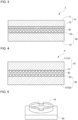
- FIG. 2 is a schematic cross-sectional view of the sliding assembly 2 according to the second embodiment of the present invention.
- the same reference numerals denote the same components in the first embodiment described above, and such components will not be described in detail (the same applies to other embodiments).
- the structure according to the present embodiment thus includes a water layer 30 between the nanosilica layer 23 in the first sliding element 10 and the nanosilica layer 23 in the second sliding element 20.
- the sliding assemblies 1 to 4 each include the first sliding element 10 having a sliding surface and the second sliding element 20 having a sliding surface.
- the first sliding element 10 includes the base member 11 and the hard layer 12 as the sliding surface on the surface of the base member 11.
- the second sliding element 20 includes the base member 21 and the hard layer 22 as the sliding surface on the surface of the base member 21.
- the sliding surface of the first sliding element 10 and the sliding surface of the second sliding element 20 come in contact with each other with the water layer 30 in between to allow the first sliding element 10 and the second sliding element 20 to slide relative to each other.
- At least one of the hard layer 12 in the first sliding element 10 or the hard layer 22 in the second sliding element 20 includes the nanosilica layer 13 or 23 supporting nanosilica particles.
- the nanosilica layer 13 or 23 has a surface covered with the water layer 30, allowing water-lubricated sliding with an appropriate sliding velocity under an appropriate load.
- the first and second sliding elements 10 and 20 can thus slide relative to each other with low friction.
- the sliding assembly with the simple structure can have high water lubricity.
- This structure allows improved water-lubricated sliding with the nanosilica layer 13 or 23 supporting nanosilica particles.
- the hard layer 12 in the first sliding element 10 includes the nanosilica layer 13
- the hard layer 22 in the second sliding element 20 includes the nanosilica layer 23.
- Each of the hard layers 12 and 22 has a Vickers hardness of 1000 Hv or higher.
- At least one of the hard layer 12 in the first sliding element 10 or the hard layer 22 in the second sliding element 20 is formed from diamond-like carbon on a surface of the base member 11 or 21.
- the diamond-like carbon may specifically contain silicon.
- the hard layer 12 in the first sliding element 10 is a part of the base member 11
- the hard layer 22 in the second sliding element 20 is a part of the base member 21.
- Each of the base member 11 including the hard layer 12 and the base member 21 including the hard layer 22 is formed from a ceramic material.
- a ring-on-disk test was conducted using, as shown in FIG. 5 , a pair of test pieces, or a ring test piece and a disk test piece, as the first sliding element 10 and the second sliding element 20 included in each of the sliding assemblies 1 to 4 according to the first to fourth embodiments.
- Each ring test piece as the first sliding element 10 is a ring having an outer diameter of 16 mm and an inner diameter of 11.4 mm and has a thickness of 7 mm.
- Each disk test piece as the second sliding element 20 is a square having sides of 20 mm and has a thickness of 4 mm.
- the friction and wear tester 100 includes a loading assembly 101 in its upper portion for applying a downward load and a rotation assembly 102 in its lower portion for rotating one of the pair of test pieces.
- the test tools 200 were used to attach the ring test piece (first sliding element 10) and the disk test piece (second sliding element 20) to the friction and wear tester 100.
- the test tools 200 include an upper tool 201 for attaching the ring test piece to the loading assembly 101 and a lower tool 202 for attaching the disk test piece to the rotation assembly 102.
- the upper tool 201 can change its angle relative to the loading assembly 101 with a steel ball 201a in between, causing the ring test piece to directly face the disk test piece constantly.
- the lower tool 202 has an upper surface with a recess that can store water. Water is supplied into the recess on the upper surface of the lower tool 202 to cause the surfaces of the ring test piece and the disk test piece facing and stacked on each other to be in the water.
- a ring test piece (first sliding element 10) in a first example includes a hard layer 12 being a Si-DLC coating containing 25% of Si and a nanosilica layer 13 supporting nanosilica particles having a particle size of 9 nm.
- a disk test piece (second sliding element 20) in the first example includes a hard layer 22 being a Si-DLC coating containing 25% of Si and a nanosilica layer 23 supporting nanosilica particles having a particle size of 9 nm.
- a friction and wear test was conducted under the same test conditions in a first comparative example.
- a ring test piece in the first comparative example includes a hard layer 12 being a Si-DLC coating containing 25% of Si and supports no nanosilica particles.
- a disk test piece in the first comparative example includes a hard layer 22 being a Si-DLC coating containing 25% of Si and supports no nanosilica particles. The same test conditions as in the first example were used.
- FIG. 8 is a graph showing friction and wear test results of the first example and the first comparative example.
- the vertical axis indicates the coefficient of friction
- the horizontal axis indicates the surface-to-surface contact pressure (the same applies to FIGs. 9 to 12 ).
- the surface-to-surface contact pressure during sliding reaches at least 48.5 MPa in the first example and 24 MPa in the first comparative example.
- the surface-to-surface contact pressure (in MPa) is the value of the normal load (in N) divided by the contact area (about 100 mm square) between the ring test piece and the disk test piece.
- the coefficient of friction during low-friction sliding is lower in the first example than in the first comparative example, thus indicating low friction.
- the results indicate that the nanosilica layers contribute to improving water-lubricated sliding.
- Low-friction sliding herein refers to sliding with a coefficient of friction of 0.1 or lower.
- the test conditions include the sliding velocity of 12 mm/s, a test piece with the dimensions of cp16 ⁇ ⁇ 11.4 ⁇ 7 mm used as the ring test piece, and a test piece with the dimensions of 20 ⁇ 20 ⁇ 4 mm used as the disk test piece.
- a normal load of 50 N was applied for 60 seconds.
- a load of 200 N greater than the preceding load was applied for 30 seconds per load.
- a load of 4800 N was maintained for 60 seconds until the end of the test.
- a ring test piece in a second comparative example includes no hard layer 12 (a base member being SUS440C) and includes a nanosilica layer 13 supporting nanosilica particles having a particle size of 9 nm.
- a disk test piece in the second comparative example includes no hard layer 22 (a base member being SUS440C) and includes a nanosilica layer 23 supporting nanosilica particles having a particle size of 9 nm. The same test conditions as in the second example were used.
- FIG. 9 is a graph showing friction and wear test results of the second example and the second comparative example.
- the graph in FIG. 9 shows data comparing, among the hard layers supporting nanosilica particles, the a-C:H in the second example with the SUS440C in the second comparative example having a Vickers hardness Hv of 653 (common value).
- two sliding surfaces (hard layers 12 and 22) each support silica particles.
- the surface-to-surface contact pressure during low-friction sliding reaches at least 48.5 MPa.
- the SUS440C in the second comparative example low friction is not achieved. This indicates that the hardness of the hard layers 12 and 22 contributes to improving water-lubricated sliding.
- the test conditions include the sliding velocity of 12 mm/s, a test piece with the dimensions of ⁇ 16 ⁇ ⁇ 11.4 ⁇ 7 mm used as the ring test piece, and a test piece with the dimensions of 20 ⁇ 20 ⁇ 4 mm used as the disk test piece.
- a normal load of 50 N was applied for 60 seconds.
- a load of 200 N greater than the preceding load was applied for 30 seconds per load.
- a load of 4800 N was maintained for 60 seconds until the end of the test.
- a test is conducted to confirm the effects of the third embodiment.
- a ring test piece (first sliding element 10) in the fourth example includes a hard layer 12 being a DLC coating containing 0% of Si (a-C:H) and supports no nanosilica particles.
- a disk test piece (second sliding element 20) in the fourth example includes a base member 21 (also serving as a hard layer 22) of silicon nitride and a nanosilica layer 23 supporting nanosilica particles having a particle size of 9 nm.
- FIG. 11 is a graph showing friction and wear test results of the fourth example and the fifth example.
- FIG. 11 shows the friction test results of the ring-on-disk tests with the base member 21 being silicon nitride or silicon carbide.
- the surface-to-surface contact pressure during low-friction sliding reaches at least 48.5 MPa. This indicates that the hard layer 22 may not be a coating of a hard film of, for example, DLC, and the sufficiently hard base member 21 can also serve as the hard layer 22.
- a ring test piece (first sliding element 10) in the seventh example includes a base member 11 of silicon carbide ceramic also serving as a hard layer 12 and a nanosilica layer 13 supporting nanosilica particles having a particle size of 9 nm.
- a disk test piece (second sliding element 20) in the seventh example includes a base member 21 of silicon carbide ceramic also serving as a hard layer 22 and a nanosilica layer 23 supporting nanosilica particles having a particle size of 9 nm.
- the test conditions include the sliding velocity of 300 mm/s, a test piece with the dimensions of ⁇ 16 ⁇ ⁇ 11.4 ⁇ 7 mm used as the ring test piece, and a test piece with the dimensions of 20 ⁇ 20 ⁇ 4 mm used as the disk test piece.
- a normal load of 50 N was applied for 60 seconds.
- a load of 200 N and then a load of 200 N greater than the preceding load were applied for 30 seconds per load.
- the coefficient of friction increased until the end of the test.
- a test was conducted to confirm that ultralow friction is stably maintained at a sliding distance of 1000 m in the seventh example.
- a ring test piece (first sliding element 10) in the eighth example includes a base member 11 of silicon carbide ceramic also serving as a hard layer 12 and a nanosilica layer 13 supporting nanosilica particles having a particle size of 9 nm.
- a disk test piece (second sliding element 20) in the seventh example includes a base member 21 of silicon carbide ceramic also serving as a hard layer 22 and a nanosilica layer 23 supporting nanosilica particles having a particle size of 9 nm.
- the test conditions include the sliding velocity of 300 mm/s, a test piece with the dimensions of ⁇ 16 ⁇ ⁇ 11.4 ⁇ 7 mm used as the ring test piece, and a test piece with the dimensions of 20 ⁇ 20 ⁇ 4 mm used as the disk test piece.
- a normal load of 50 N was applied for 60 seconds.
- a load of 200 N and then a load of 200 N greater than the preceding load were applied for 30 seconds per load.
- the coefficient of friction increased until the end of the test.
- the structure according to one or more embodiments of the present invention may be used for a sliding assembly and a device including the sliding assembly.
- a sliding assembly includes a first sliding element and a second sliding element each having a sliding surface.
- the sliding surfaces come in contact with each other with a water layer in between to allow the first and second sliding elements to slide relative to each other.
- the sliding assembly can be, for example, used as a sliding assembly in, for example, a seal for a fluid device such as a piston ring and a cylinder, a slide bearing, or a mechanical seal for a rotary shaft, or in various fields including vehicles and machine tools using the sliding assembly.
Landscapes
- Engineering & Computer Science (AREA)
- General Engineering & Computer Science (AREA)
- Mechanical Engineering (AREA)
- Chemical & Material Sciences (AREA)
- Ceramic Engineering (AREA)
- Sliding-Contact Bearings (AREA)
- Lubricants (AREA)
Abstract
Description
- The present invention relates to a sliding assembly, and particularly, to a sliding assembly using water lubrication.
- Mechanical seals containing a ceramic material with water lubrication have been used for bearings in submersible pumps or other components (refer to, for example, Patent Literature 1).
Patent Literature 1 describes a technique used in a pin-on-disk test for a ceramic material to have water lubricity using a coating with siloxane linkages on the ceramic surface by adding a silane coupling agent to the ceramic material. - Another known technique uses a hard carbon film of, for example, diamond-like carbon as a coating material for, for example, sliding members (refer to, for example, Patent Literature 2).
-
- Patent Literature 1:
Japanese Unexamined Patent Application Publication No. 01-290577 - Patent Literature 2:
Japanese Patent No. 6095090 - The ceramic material used with the known technique described in
Patent Literature 1 is difficult to process and is costly. Such a known technique has practical issues resulting from the addition of an appropriate amount of aqueous solution to a friction surface. - The known technique described in
Patent Literature 2 uses workhours for a conformity process between a first sliding member and a second sliding member in a fluid-free environment until the average height of droplets on the first sliding member is smaller than the amount of elastic deformation in the first sliding member under the load from the second sliding member during sliding between the first sliding member and the second sliding member. - In response to the above issues, one or more aspects of the present invention are directed to a sliding assembly with a simple structure that allows smooth water-lubricated sliding.
- A sliding assembly according to one or more aspects of the present invention includes a first sliding element having a sliding surface and a second sliding element having a sliding surface. The first sliding element includes a first base member and a first hard layer as the sliding surface on a surface of the first base member. The second sliding element includes a second base member and a second hard layer as the sliding surface on a surface of the second base member. The sliding surface of the first sliding element and the sliding surface of the second sliding element come in contact with each other with a water layer in between to allow the first sliding element and the second sliding element to slide relative to each other. At least one of the first hard layer in the first sliding element or the second hard layer in the second sliding element includes a nanosilica layer supporting nanosilica particles.
- In the sliding assembly according to one or more aspects of the present invention, the at least one of the first hard layer or the second hard layer has a surface with hydroxyl groups.
- In the sliding assembly according to one or more aspects of the present invention, the nanosilica layer is supported by the at least one of the first hard layer or the second hard layer based on covalent bonds between the hydroxyl groups activated in the at least one of the first hard layer or the second hard layer and hydroxyl groups in the nanosilica particles.
- In the sliding assembly according to one or more aspects of the present invention, each of the first hard layer in the first sliding element and the second hard layer in the second sliding element includes the nanosilica layer.
- In the sliding assembly according to one or more aspects of the present invention, each of the first hard layer and the second hard layer has a Vickers hardness of 1000 Hv or higher.
- In the sliding assembly according to one or more aspects of the present invention, at least one of the first hard layer in the first sliding element or the second hard layer in the second sliding element is formed from diamond-like carbon on a surface of at least one of the first base member or the second base member.
- In the sliding assembly according to one or more aspects of the present invention, the diamond-like carbon contains silicon.
- In the sliding assembly according to one or more aspects of the present invention, at least one of the first hard layer in the first sliding element or the second hard layer in the second sliding element is a part of at least one of the first base member or the second base member.
- In the sliding assembly according to one or more aspects of the present invention, the at least one of first base member or the second base member including the at least one of the first hard layer or the second hard layer is formed from a ceramic material.
- In the sliding assembly according to one or more aspects of the present invention, the first hard layer in the first sliding element is a part of the first base member, and the second hard layer in the second sliding element is a part of the second base member. Each of the first base member including the first hard layer and the second base member including the second hard layer is formed from a ceramic material.
- The sliding assembly according to the above aspects of the present invention includes the nanosilica layer having a surface covered with the water layer to have water lubricity with an appropriate sliding velocity under an appropriate load, causing the first and second sliding elements to slide relative to each other with low friction. The sliding assembly with the simple structure allows smooth water-lubricated sliding.
-
-
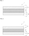
FIG. 1 is a schematic cross-sectional view of a sliding assembly according to a first embodiment of the present invention. -
FIG. 2 is a schematic cross-sectional view of a sliding assembly according to a second embodiment of the present invention. -
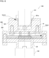
FIG. 3 is a schematic cross-sectional view of a sliding assembly according to a third embodiment of the present invention. -
FIG. 4 is a schematic cross-sectional view of a sliding assembly according to a fourth embodiment of the present invention. -
FIG. 5 is a perspective view of a pair of test pieces to undergo a friction and wear test. -
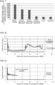
FIG. 6 is a cross-sectional view of a friction and wear tester and test tools used in the friction and wear test. -
FIG. 7 is a graph showing the difference between oxygen counts on test pieces before and after nanosilica particles are supported. -
FIG. 8 is a graph showing friction and wear test results of a first example and a first comparative example. -
FIG. 9 is a graph showing friction and wear test results of a second example and a second comparative example. -
FIG. 10 is a graph showing friction and wear test results of a third example. -
FIG. 11 is a graph showing friction and wear test results of a fourth example and a fifth example. -
FIG. 12 is a graph showing friction and wear test results of a sixth example. -
FIG. 13 is a graph showing friction and wear test results of a seventh example and a third comparative example. -
FIG. 14 is a graph showing friction and wear test results of an eighth example. -
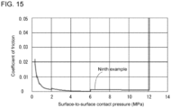
FIG. 15 is a graph showing friction and wear test results of a ninth example. - Sliding assemblies according to embodiments of the present invention will now be described with reference to the drawings.
- A
sliding assembly 1 according to a first embodiment of the present invention will be described first with reference toFIG. 1. FIG. 1 is a schematic cross-sectional view of thesliding assembly 1 according to the first embodiment of the present invention. - The
sliding assembly 1 includes a first slidingelement 10 and a second slidingelement 20 each having a sliding surface. The sliding surfaces come in contact with each other with awater layer 30 in between to allow the first and secondsliding elements - The first sliding
element 10 includes abase member 11 and ahard layer 12 as a sliding surface on a surface of thebase member 11. The second slidingelement 20 includes abase member 21 and ahard layer 22 as a sliding surface on a surface of thebase member 21. - The
base members base members base members - The
hard layers base members hard layers - The
hard layers sliding elements nanosilica layers - The
nanosilica layers hard layers hard layers hard layers hard layers elements hard layers - The
water layer 30 is located between the nanosilica layers 13 and 23 to cover the surfaces of the nanosilica layers 13 and 23. The nanosilica layers 13 and 23 are stacked on each other with thewater layer 30 in between. The structure then slides with an appropriate sliding velocity under an appropriate load to have water lubricity. - A sliding
assembly 2 according to a second embodiment of the present invention will now be described with reference toFIG. 2. FIG. 2 is a schematic cross-sectional view of the slidingassembly 2 according to the second embodiment of the present invention. The same reference numerals denote the same components in the first embodiment described above, and such components will not be described in detail (the same applies to other embodiments). - In the above first embodiment, the
hard layers elements FIG. 2 , ahard layer 22 in a second slidingelement 20 alone includes ananosilica layer 23, whereas ahard layer 12 in a first slidingelement 10 includes nonanosilica layer 13. - The structure according to the present embodiment thus includes a
water layer 30 between a surface of thehard layer 12 in the first slidingelement 10 and thenanosilica layer 23 in the second slidingelement 20. - A sliding
assembly 3 according to a third embodiment of the present invention will now be described with reference toFIG. 3. FIG. 3 is a schematic cross-sectional view of the slidingassembly 3 according to the third embodiment of the present invention. - In the present embodiment, a first sliding
element 10 includes abase member 11 formed from the same steel material (e.g., SUS440C) as in the first embodiment. In contrast, a second slidingelement 20 includes abase member 21 formed from a ceramic material (e.g., silicon nitride or silicon carbide). Thebase member 21 also serves as thehard layer 22 in the first embodiment. Thebase member 21 in the second slidingelement 20 alone includes ananosilica layer 23 on its surface, whereas ahard layer 12 in the first slidingelement 10 includes nonanosilica layer 13. - The structure according to the present embodiment thus includes a
water layer 30 between a surface of thehard layer 12 in the first slidingelement 10 and thenanosilica layer 23 in the second slidingelement 20. - A sliding
assembly 4 according to a fourth embodiment of the present invention will now be described with reference toFIG. 4. FIG. 4 is a schematic cross-sectional view of the slidingassembly 4 according to the fourth embodiment of the present invention. - In the present embodiment, a first sliding
element 10 includes abase member 11 formed from a ceramic material (e.g., silicon nitride or silicon carbide). Thebase member 11 also serves as thehard layer 12 in the first embodiment. Thebase member 11 in the first slidingelement 10 includes ananosilica layer 13 on its surface. Similarly, a second slidingelement 20 includes abase member 21 formed from a ceramic material (e.g., silicon nitride or silicon carbide). Thebase member 21 also serves as thehard layer 22 in the first embodiment. Thebase member 21 in the second slidingelement 20 includes ananosilica layer 23 on its surface. - The structure according to the present embodiment thus includes a
water layer 30 between thenanosilica layer 23 in the first slidingelement 10 and thenanosilica layer 23 in the second slidingelement 20. - The sliding
assemblies 1 to 4 according to the first to fourth embodiments of the present invention each include the first slidingelement 10 having a sliding surface and the second slidingelement 20 having a sliding surface. The first slidingelement 10 includes thebase member 11 and thehard layer 12 as the sliding surface on the surface of thebase member 11. The second slidingelement 20 includes thebase member 21 and thehard layer 22 as the sliding surface on the surface of thebase member 21. The sliding surface of the first slidingelement 10 and the sliding surface of the second slidingelement 20 come in contact with each other with thewater layer 30 in between to allow the first slidingelement 10 and the second slidingelement 20 to slide relative to each other. At least one of thehard layer 12 in the first slidingelement 10 or thehard layer 22 in the second slidingelement 20 includes thenanosilica layer - In this structure, the
nanosilica layer water layer 30, allowing water-lubricated sliding with an appropriate sliding velocity under an appropriate load. The first and second slidingelements - The
hard layer nanosilica layer nanosilica layer hard layer hard layer - This structure allows improved water-lubricated sliding with the
nanosilica layer - In the sliding
assembly 1 according to the first embodiment, thehard layer 12 in the first slidingelement 10 includes thenanosilica layer 13, and thehard layer 22 in the second slidingelement 20 includes thenanosilica layer 23. - With the nanosilica layers 13 and 23 in the respective first and second sliding
elements - Each of the
hard layers - With the
hard layers - In the sliding
assembly 1 according to the first embodiment and the slidingassembly 2 according to the second embodiment, at least one of thehard layer 12 in the first slidingelement 10 or thehard layer 22 in the second slidingelement 20 is formed from diamond-like carbon on a surface of thebase member - This structure including the
hard layer base member - In the sliding
assembly 3 according to the third embodiment, at least one of thehard layer 12 in the first slidingelement 10 or thehard layer 22 in the second slidingelement 20 is a part of thebase member base member hard layer - This structure uses a sufficiently hard material (e.g., a ceramic material such as silicon nitride or silicon carbide) as the
base member hard layer - In the sliding
assembly 4 according to the fourth embodiment, thehard layer 12 in the first slidingelement 10 is a part of thebase member 11, and thehard layer 22 in the second slidingelement 20 is a part of thebase member 21. Each of thebase member 11 including thehard layer 12 and thebase member 21 including thehard layer 22 is formed from a ceramic material. - This structure uses a sufficiently hard material (e.g., a ceramic material such as silicon nitride or silicon carbide) as the
base members hard layers - Examples in the above embodiments will be described below. An overview of a friction and wear test common to the examples will now be described with reference to
FIGs. 5 to 7 .FIG. 5 is a perspective view of a pair of test pieces to undergo the friction and wear test.FIG. 6 is a cross-sectional view of a friction and weartester 100 andtest tools 200 used in the friction and wear test.FIG. 7 is a graph showing the difference between oxygen counts on test pieces before and after nanosilica particles are supported. - In each example, a ring-on-disk test was conducted using, as shown in
FIG. 5 , a pair of test pieces, or a ring test piece and a disk test piece, as the first slidingelement 10 and the second slidingelement 20 included in each of the slidingassemblies 1 to 4 according to the first to fourth embodiments. Each ring test piece as the first slidingelement 10 is a ring having an outer diameter of 16 mm and an inner diameter of 11.4 mm and has a thickness of 7 mm. Each disk test piece as the second slidingelement 20 is a square having sides of 20 mm and has a thickness of 4 mm. - The friction and wear tests in the examples were conducted with a friction and wear tester, EFM-III-H model, (A&D Company, Limited). As shown in
FIG. 6 , the friction and weartester 100 includes aloading assembly 101 in its upper portion for applying a downward load and arotation assembly 102 in its lower portion for rotating one of the pair of test pieces. - The
test tools 200 were used to attach the ring test piece (first sliding element 10) and the disk test piece (second sliding element 20) to the friction and weartester 100. Thetest tools 200 include anupper tool 201 for attaching the ring test piece to theloading assembly 101 and alower tool 202 for attaching the disk test piece to therotation assembly 102. Theupper tool 201 can change its angle relative to theloading assembly 101 with asteel ball 201a in between, causing the ring test piece to directly face the disk test piece constantly. Thelower tool 202 has an upper surface with a recess that can store water. Water is supplied into the recess on the upper surface of thelower tool 202 to cause the surfaces of the ring test piece and the disk test piece facing and stacked on each other to be in the water. - In each example, a scanning electron microscope and an energy-dispersive X-ray detector are used for counting the amount of oxygen on the test pieces to determine the difference between oxygen counts before and after nanosilica particles are supported (refer to
FIG. 7 ). The amount of nanosilica particles being supported can be estimated by counting the amount of oxygen that is contained in the nanosilica layer but is not contained in the hard layer. The counted amount of oxygen differs based on the amount of surface hydroxyl groups on the hard layers. The above method can thus observe the amount of nanosilica particles being supported. - A ring test piece (first sliding element 10) in a first example includes a
hard layer 12 being a Si-DLC coating containing 25% of Si and ananosilica layer 13 supporting nanosilica particles having a particle size of 9 nm. Similarly, a disk test piece (second sliding element 20) in the first example includes ahard layer 22 being a Si-DLC coating containing 25% of Si and ananosilica layer 23 supporting nanosilica particles having a particle size of 9 nm. - The test conditions include the sliding velocity of 12 mm/s, a test piece with the dimensions of ϕ16 × ϕ11.4 × 7 mm (indicating an outer diameter of 16 mm, an inner diameter of 11.4 mm, and a thickness of 7 mm, the same applies to the other examples) used as the ring test piece, and a test piece with the dimensions of 20 × 20 × 4 mm used as the disk test piece. A normal load of 50 N was applied for 60 seconds. Subsequently, from 200 to 4800 N, a load of 200 N greater than the preceding load was applied for 30 seconds per load. A load of 4800 N was maintained for 60 seconds until the end of the test.
- For comparison with the first example, a friction and wear test was conducted under the same test conditions in a first comparative example. A ring test piece in the first comparative example includes a
hard layer 12 being a Si-DLC coating containing 25% of Si and supports no nanosilica particles. Similarly, a disk test piece in the first comparative example includes ahard layer 22 being a Si-DLC coating containing 25% of Si and supports no nanosilica particles. The same test conditions as in the first example were used. -
FIG. 8 is a graph showing friction and wear test results of the first example and the first comparative example. In the graph inFIG. 8 , the vertical axis indicates the coefficient of friction, and the horizontal axis indicates the surface-to-surface contact pressure (the same applies toFIGs. 9 to 12 ). As shown inFIG. 8 , the surface-to-surface contact pressure during sliding reaches at least 48.5 MPa in the first example and 24 MPa in the first comparative example. The surface-to-surface contact pressure (in MPa) is the value of the normal load (in N) divided by the contact area (about 100 mm square) between the ring test piece and the disk test piece. The coefficient of friction during low-friction sliding is lower in the first example than in the first comparative example, thus indicating low friction. The results indicate that the nanosilica layers contribute to improving water-lubricated sliding. Low-friction sliding herein refers to sliding with a coefficient of friction of 0.1 or lower. - A ring test piece (first sliding element 10) in a second example includes a
hard layer 12 being a DLC coating containing 0% of Si (hydrogenated amorphous carbon, hereafter referred to as a-C:H) and ananosilica layer 13 supporting nanosilica particles having a particle size of 9 nm. Similarly, a disk test piece (second sliding element 20) in the second example includes ahard layer 22 being a DLC coating containing 0% of Si (a-C:H) and ananosilica layer 23 supporting nanosilica particles having a particle size of 9 nm. - The test conditions include the sliding velocity of 12 mm/s, a test piece with the dimensions of cp16 × ϕ11.4 × 7 mm used as the ring test piece, and a test piece with the dimensions of 20 × 20 × 4 mm used as the disk test piece. A normal load of 50 N was applied for 60 seconds. Subsequently, from 200 to 4800 N, a load of 200 N greater than the preceding load was applied for 30 seconds per load. A load of 4800 N was maintained for 60 seconds until the end of the test.
- A ring test piece in a second comparative example includes no hard layer 12 (a base member being SUS440C) and includes a
nanosilica layer 13 supporting nanosilica particles having a particle size of 9 nm. Similarly, a disk test piece in the second comparative example includes no hard layer 22 (a base member being SUS440C) and includes ananosilica layer 23 supporting nanosilica particles having a particle size of 9 nm. The same test conditions as in the second example were used. -
FIG. 9 is a graph showing friction and wear test results of the second example and the second comparative example. In other words, the graph inFIG. 9 shows data comparing, among the hard layers supporting nanosilica particles, the a-C:H in the second example with the SUS440C in the second comparative example having a Vickers hardness Hv of 653 (common value). In the second example and the second comparative example, two sliding surfaces (hard layers 12 and 22) each support silica particles. With the a-C:H in the second example, the surface-to-surface contact pressure during low-friction sliding reaches at least 48.5 MPa. With the SUS440C in the second comparative example, low friction is not achieved. This indicates that the hardness of thehard layers - In a third example, a test is conducted to confirm the effects of the second embodiment. A ring test piece (first sliding element 10) in the third example includes a
hard layer 12 being a DLC coating containing 0% of Si (a-C:H) and supports no nanosilica particles. A disk test piece (second sliding element 20) in the second example includes ahard layer 22 being a DLC coating containing 25% of Si and ananosilica layer 23 supporting nanosilica particles having a particle size of 9 nm. - The test conditions include the sliding velocity of 12 mm/s, a test piece with the dimensions of ϕ16 × ϕ11.4 × 7 mm used as the ring test piece, and a test piece with the dimensions of 20 × 20 × 4 mm used as the disk test piece. A normal load of 50 N was applied for 60 seconds. Subsequently, from 200 to 4800 N, a load of 200 N greater than the preceding load was applied for 30 seconds per load. A load of 4800 N was maintained for 60 seconds until the end of the test.
-
FIG. 10 is a graph showing friction and wear test results of the third example. The ring test piece includes thehard layer 12 of a-C:H and supports no silica particles. The disk test piece includes thehard layer 22 being a Si-DLC coating containing 25% of Si and supports nanosilica particles having a particle size of 9 nm. As shown inFIG. 10 , the surface-to-surface contact pressure during low-friction sliding reaches at least 48.5 MPa. The results of the third example indicate that low friction is achieved with a single surface (hard layer 22) alone supporting silica particles. - In a fourth example, a test is conducted to confirm the effects of the third embodiment. A ring test piece (first sliding element 10) in the fourth example includes a
hard layer 12 being a DLC coating containing 0% of Si (a-C:H) and supports no nanosilica particles. A disk test piece (second sliding element 20) in the fourth example includes a base member 21 (also serving as a hard layer 22) of silicon nitride and ananosilica layer 23 supporting nanosilica particles having a particle size of 9 nm. - The test conditions include the sliding velocity of 12 mm/s, a test piece with the dimensions of ϕ16 × ϕ11.4 × 7 mm used as the ring test piece, and a test piece with the dimensions of 20 × 20 × 4 mm used as the disk test piece. A normal load of 50 N was applied for 60 seconds. Subsequently, from 200 to 4800 N, a load of 200 N greater than the preceding load was applied for 30 seconds per load. A load of 4800 N was maintained for 60 seconds until the end of the test.
- In a fifth example, similarly to the fourth example, a test was conducted to confirm the effects of the third embodiment. A ring test piece (first sliding element 10) in the fifth example includes a
hard layer 12 being a DLC coating containing 0% of Si (a-C:H) and supports no nanosilica particles. A disk test piece (second sliding element 20) in the fifth example includes a base member 21 (also serving as a hard layer 22) of silicon carbide and ananosilica layer 23 supporting nanosilica particles having a particle size of 9 nm. The same test conditions as in the fourth example were used. -
FIG. 11 is a graph showing friction and wear test results of the fourth example and the fifth example.FIG. 11 shows the friction test results of the ring-on-disk tests with thebase member 21 being silicon nitride or silicon carbide. As shown inFIG. 11 , the surface-to-surface contact pressure during low-friction sliding reaches at least 48.5 MPa. This indicates that thehard layer 22 may not be a coating of a hard film of, for example, DLC, and the sufficientlyhard base member 21 can also serve as thehard layer 22. - A ring test piece (first sliding element 10) in a sixth example includes a
hard layer 12 being a DLC coating containing 25% of Si and ananosilica layer 13 supporting nanosilica particles having a particle size of 9 nm. A disk test piece (second sliding element 20) in the sixth example includes ahard layer 22 being a DLC coating containing 25% of Si and ananosilica layer 23 supporting nanosilica particles having a particle size of 9 nm. - The test conditions include the sliding velocity of 100 mm/s, a test piece with the dimensions of cp 16 × ϕ11.4 × 7 mm used as the ring test piece, and a test piece with the dimensions of 20 × 20 × 4 mm used as the disk test piece. A normal load of 50 N was applied for 60 seconds. Subsequently, from 200 to 4800 N, a load of 200 N greater than the preceding load was applied for 30 seconds per load. A load of 4800 N was maintained for 60 seconds until the end of the test.
-
FIG. 12 is a graph showing friction and wear test results of the sixth example, showing friction test results of the ring-on-disk test with the sliding velocity changed to 100 mm/s. As shown inFIG. 12 , the surface-to-surface contact pressure during low-friction sliding reaches at least 48.5 Mpa. The results of the sixth example show that low-friction sliding is maintained with a sliding velocity of 100 mm/s. - In a seventh example, a test was conducted to confirm the effects of the fourth embodiment. A ring test piece (first sliding element 10) in the seventh example includes a
base member 11 of silicon carbide ceramic also serving as ahard layer 12 and ananosilica layer 13 supporting nanosilica particles having a particle size of 9 nm. Similarly to the ring test piece, a disk test piece (second sliding element 20) in the seventh example includes abase member 21 of silicon carbide ceramic also serving as ahard layer 22 and ananosilica layer 23 supporting nanosilica particles having a particle size of 9 nm. - The test conditions include the sliding velocity of 300 mm/s, a test piece with the dimensions of ϕ16 × ϕ11.4 × 7 mm used as the ring test piece, and a test piece with the dimensions of 20 × 20 × 4 mm used as the disk test piece. A normal load of 50 N was applied for 60 seconds. Subsequently, a load of 200 N and then a load of 200 N greater than the preceding load were applied for 30 seconds per load. At 1080 N, the coefficient of friction increased until the end of the test.
- For comparison with the seventh example, a friction and wear test was conducted under the same test conditions in a third comparative example. A ring test piece (first sliding element 10) in the third comparative example includes a
base member 11 of silicon carbide ceramic also serving as ahard layer 12 and supports no nanosilica particles. Similarly to the ring test piece, a disk test piece (second sliding element 20) in the seventh example includes abase member 21 of silicon carbide ceramic also serving as ahard layer 22 and supports no nanosilica particles. A normal load of 50N was applied for 60 seconds. Subsequently, a load of 200 N and then a load of 200 N greater than the preceding load were applied for 30 seconds per load. At 400 N, the coefficient of friction increased until the end of the test. -
FIG. 13 is a graph showing friction and wear test results of the seventh example and the third comparative example. In the graph inFIG. 13 , the vertical axis indicates the coefficient of friction, and the horizontal axis indicates the surface-to-surface contact pressure. As shown inFIG. 13 , the surface-to-surface contact pressure during slidingreaches 10 Mpa in the seventh example as the load applied in a stepwise manner. In contrast, the surface-to-surface contact pressure is 4 Mpa in the third comparative example. The minimum coefficient of friction in the seventh example is lower than or equal to 0.001, which is below 0.01, thus achieving ultralow-friction sliding. The ultralow-friction sliding herein refers to sliding with a coefficient of friction lower than or equal to 0.01. - In an eighth example, a test was conducted to confirm that ultralow friction is stably maintained at a sliding distance of 1000 m in the seventh example. A ring test piece (first sliding element 10) in the eighth example includes a
base member 11 of silicon carbide ceramic also serving as ahard layer 12 and ananosilica layer 13 supporting nanosilica particles having a particle size of 9 nm. Similarly to the ring test piece, a disk test piece (second sliding element 20) in the seventh example includes abase member 21 of silicon carbide ceramic also serving as ahard layer 22 and ananosilica layer 23 supporting nanosilica particles having a particle size of 9 nm. - The test conditions include the sliding velocity of 300 mm/s, a test piece with the dimensions of ϕ16 × ϕ11.4 × 7 mm used as the ring test piece, and a test piece with the dimensions of 20 × 20 × 4 mm used as the disk test piece. A normal load of 50 N was applied for 60 seconds. Subsequently, from 100 to 500 N, a load of 100 N greater than the preceding load was applied for 30 seconds per load. A load of 500 N was maintained until the sliding distance reached 1000 m.
-
FIG. 14 is a graph showing friction and wear test results of the eighth example, with the left vertical axis indicating the surface-to-surface contact pressure, the right vertical axis indicating the coefficient of friction, and the horizontal axis indicating the sliding distance. In the eighth example, as shown inFIG. 14 , the coefficient of friction is about 0.002, which is below 0.01, with the surface-to-surface contact pressure being 5 Mpa for the sliding distance up to 1000 m. This indicates that sliding occurs with ultralow friction being maintained. - A ring test piece (first sliding element 10) in a ninth example includes a
hard layer 12 being a DLC coating containing 50% of Si and ananosilica layer 13 supporting nanosilica particles having a particle size of 9 nm. A disk test piece (second sliding element 20) in the eighth example includes ahard layer 22 being a DLC coating containing 50% of Si and ananosilica layer 23 supporting nanosilica particles having a particle size of 9 nm. - The test conditions include the sliding velocity of 300 mm/s, a test piece with the dimensions of ϕ16 × ϕ11.4 × 7 mm used as the ring test piece, and a test piece with the dimensions of 20 × 20 × 4 mm used as the disk test piece. A normal load of 50 N was applied for 60 seconds. Subsequently, a load of 200 N and then a load of 200 N greater than the preceding load were applied for 30 seconds per load. At 1200 N, the coefficient of friction increased until the end of the test.
-
FIG. 15 is a graph showing friction and wear test results of the ninth example. In the ninth example, as shown inFIG. 15 , the coefficient of friction is far below 0.01 for the surface-to-surface contact pressure being 1 to 12 MPa, indicating that ultralow-friction sliding with the coefficient of friction below 0.01 is achieved. - The present invention is not limited to the embodiments or the examples described above and may be modified in various manners without departing from the spirit of the present invention. Although the first sliding
element 10 is a ring test piece and the second slidingelement 20 is a disk test piece in the examples described above, these elements are not limited to such pieces. For example, the first slidingelement 10 and the second slidingelement 20 may be a larger-diameter cylinder and a smaller-diameter cylinder, and water-lubricated sliding may occur between the inner circumferential surface of the larger-diameter cylinder and the outer circumferential surface of the smaller-diameter cylinder. In other embodiments, the first slidingelement 10 and the second slidingelement 20 may be a pair of plates or blocks each having a flat sliding surface, and water-lubricated sliding may occur between the flat sliding surfaces. - The structure according to one or more embodiments of the present invention may be used for a sliding assembly and a device including the sliding assembly. Such a sliding assembly includes a first sliding element and a second sliding element each having a sliding surface. The sliding surfaces come in contact with each other with a water layer in between to allow the first and second sliding elements to slide relative to each other. The sliding assembly can be, for example, used as a sliding assembly in, for example, a seal for a fluid device such as a piston ring and a cylinder, a slide bearing, or a mechanical seal for a rotary shaft, or in various fields including vehicles and machine tools using the sliding assembly.
-
- 1
- sliding assembly (first embodiment)
- 2
- sliding assembly (second embodiment)
- 3
- sliding assembly (third embodiment)
- 4
- sliding assembly (fourth embodiment)
- 10
- first sliding element
- 11
- base member
- 12
- hard layer
- 13
- nanosilica layer
- 20
- second sliding element
- 21
- base member
- 22
- hard layer
- 23
- nanosilica layer
- 30
- water layer
Claims (10)
- A sliding assembly, comprising:a first sliding element having a sliding surface, the first sliding element including a first base member and a first hard layer as the sliding surface on a surface of the first base member; anda second sliding element having a sliding surface, the second sliding element including a second base member and a second hard layer as the sliding surface on a surface of the second base member,wherein the sliding surface of the first sliding element and the sliding surface of the second sliding element come in contact with each other with a water layer in between to allow the first sliding element and the second sliding element to slide relative to each other, andat least one of the first hard layer in the first sliding element or the second hard layer in the second sliding element includes a nanosilica layer supporting nanosilica particles.
- The sliding assembly according to claim 1, wherein
the at least one of the first hard layer or the second hard layer has a surface with hydroxyl groups. - The sliding assembly according to claim 1, wherein
the nanosilica layer is supported by the at least one of the first hard layer or the second hard layer based on covalent bonds between the hydroxyl groups activated in the at least one of the first hard layer or the second hard layer and hydroxyl groups in the nanosilica particles. - The sliding assembly according to any one of claims 1 to 3, wherein
each of the first hard layer in the first sliding element and the second hard layer in the second sliding element includes the nanosilica layer. - The sliding assembly according to any one of claims 1 to 3, wherein
each of the first hard layer and the second hard layer has a Vickers hardness of 1000 Hv or higher. - The sliding assembly according to claim 5, wherein
at least one of the first hard layer in the first sliding element or the second hard layer in the second sliding element comprises diamond-like carbon on a surface of at least one of the first base member or the second base member. - The sliding assembly according to claim 6, wherein
the diamond-like carbon comprises silicon. - The sliding assembly according to any one of claims 1 to 3, wherein
at least one of the first hard layer in the first sliding element or the second hard layer in the second sliding element is a part of at least one of the first base member or the second base member. - The sliding assembly according to claim 8, wherein
the at least one of first base member or the second base member including the at least one of the first hard layer or the second hard layer comprises a ceramic material. - The sliding assembly according to claim 8, whereinthe first hard layer in the first sliding element is a part of the first base member, and the second hard layer in the second sliding element is a part of the second base member, andeach of the first base member including the first hard layer and the second base member including the second hard layer comprises a ceramic material.
Applications Claiming Priority (2)
| Application Number | Priority Date | Filing Date | Title |
|---|---|---|---|
| JP2021138707 | 2021-08-27 | ||
| PCT/JP2022/031662 WO2023027055A1 (en) | 2021-08-27 | 2022-08-23 | Sliding structure |
Publications (2)
| Publication Number | Publication Date |
|---|---|
| EP4394195A1 true EP4394195A1 (en) | 2024-07-03 |
| EP4394195A4 EP4394195A4 (en) | 2025-09-17 |
Family
ID=85322786
Family Applications (1)
| Application Number | Title | Priority Date | Filing Date |
|---|---|---|---|
| EP22861343.6A Pending EP4394195A4 (en) | 2021-08-27 | 2022-08-23 | SLIDING STRUCTURE |
Country Status (5)
| Country | Link |
|---|---|
| US (1) | US20240255026A1 (en) |
| EP (1) | EP4394195A4 (en) |
| JP (1) | JP7481690B2 (en) |
| CN (1) | CN117730210A (en) |
| WO (1) | WO2023027055A1 (en) |
Family Cites Families (15)
| Publication number | Priority date | Publication date | Assignee | Title |
|---|---|---|---|---|
| JPH01290577A (en) | 1988-05-19 | 1989-11-22 | Agency Of Ind Science & Technol | Method for improving water lubricity of ceramic material |
| JPH0533812A (en) * | 1991-05-10 | 1993-02-09 | Oiles Ind Co Ltd | Silicon dioxide sliding member |
| JPH0684021U (en) * | 1993-05-13 | 1994-12-02 | 三菱重工業株式会社 | Axial force support mechanism |
| JPH08247150A (en) * | 1995-03-09 | 1996-09-24 | Toto Ltd | Combination of in-liquid sliding member and selecting method thereof |
| US5961218A (en) * | 1996-02-20 | 1999-10-05 | Ebara Corporation | Water lubricated machine component having contacting sliding surfaces |
| GB9817249D0 (en) * | 1998-08-07 | 1998-10-07 | Glacier Vandervell Ltd | Bearing material |
| JP2000346059A (en) * | 1999-06-04 | 2000-12-12 | Daido Steel Co Ltd | Dynamic gas bearing |
| JP2004106355A (en) * | 2002-09-18 | 2004-04-08 | National Institute Of Advanced Industrial & Technology | Ceramic composite sliding member |
| GB0314372D0 (en) | 2003-06-20 | 2003-07-23 | Dana Corp | Bearings |
| JP2010255682A (en) * | 2009-04-22 | 2010-11-11 | Nsk Ltd | Method for preventing DLC film peeling of rolling sliding member, and method for using rolling support device |
| JP2011026398A (en) * | 2009-07-23 | 2011-02-10 | Yamatake Corp | Sliding structure |
| WO2015163389A1 (en) | 2014-04-24 | 2015-10-29 | 国立大学法人東北大学 | Sliding method, production method for sliding structure, sliding structure, and device |
| JP6872452B2 (en) | 2017-07-27 | 2021-05-19 | 株式会社豊田中央研究所 | Die casting mold and die casting method |
| TWI764109B (en) * | 2019-03-22 | 2022-05-11 | 美商聖高拜塑膠製品公司 | Composite bearing and method of making and using the same |
| EP4039465B1 (en) * | 2019-09-30 | 2025-07-23 | Asahi Rubber Inc. | Slidable rubber material having amino-modified interfacial modification layer, and method for producing said slidable rubber material |
-
2022
- 2022-08-23 CN CN202280037341.9A patent/CN117730210A/en active Pending
- 2022-08-23 US US18/560,421 patent/US20240255026A1/en active Pending
- 2022-08-23 EP EP22861343.6A patent/EP4394195A4/en active Pending
- 2022-08-23 JP JP2023543921A patent/JP7481690B2/en active Active
- 2022-08-23 WO PCT/JP2022/031662 patent/WO2023027055A1/en not_active Ceased
Also Published As
| Publication number | Publication date |
|---|---|
| US20240255026A1 (en) | 2024-08-01 |
| JP7481690B2 (en) | 2024-05-13 |
| WO2023027055A1 (en) | 2023-03-02 |
| CN117730210A (en) | 2024-03-19 |
| EP4394195A4 (en) | 2025-09-17 |
| JPWO2023027055A1 (en) | 2023-03-02 |
Similar Documents
| Publication | Publication Date | Title |
|---|---|---|
| Wang et al. | Rolling contact silicon nitride bearing technology: a review of recent research | |
| KR100925071B1 (en) | Thin-wall bearing | |
| EP2013484B1 (en) | Coating for gas bearings | |
| JPH08105447A (en) | Seal or bearing | |
| EP0816698A1 (en) | Lubricated rolling contact devices, a method for lubricating these and a composition suitable for such lubrication | |
| JP2024506966A (en) | low friction coating | |
| JP6095090B2 (en) | Sliding method, manufacturing method of sliding structure, sliding structure and device | |
| US20240255026A1 (en) | Sliding assembly | |
| CN112739922B (en) | Rolling bearings and main shaft support devices for wind power generation | |
| WO2001018273A1 (en) | Rolling bearing | |
| Kalin et al. | Effect of fretting conditions on the wear of silicon nitride against bearing steel | |
| US12098750B2 (en) | Sliding components | |
| JP2008274984A (en) | Conveying roller and vacuum conveying apparatus provided with the same | |
| Kröner et al. | Greenbearings–friction behaviour of DLC-coated dry running deep groove ball bearings | |
| JP2001248708A (en) | Rolling device | |
| JP2005351443A (en) | Rolling support device and vacuum conveyance device | |
| Masuko et al. | Lubrication performance of multialkylatedcyclopentane oils for sliding friction of steel under vacuum condition | |
| WO2008143589A1 (en) | Refrigerant compressor sliding surface with non-integral reaction layer | |
| Bolotov et al. | Nanodispersed ferrofluid oil lubricity improvement with processing methods | |
| JP4823616B2 (en) | Sliding unit and sliding method | |
| JP2021055696A (en) | Touchdown rolling bearing | |
| JP2008274985A (en) | Touchdown bearing | |
| JP2009210014A (en) | Carrying roller and vacuum carrying device equipped therewith | |
| US20080178795A1 (en) | Gas Bearing Spindles | |
| Sorrell et al. | Tribological performance of hard coatings and polymer interfaces under the effect of lunar regolith |
Legal Events
| Date | Code | Title | Description |
|---|---|---|---|
| STAA | Information on the status of an ep patent application or granted ep patent |
Free format text: STATUS: THE INTERNATIONAL PUBLICATION HAS BEEN MADE |
|
| PUAI | Public reference made under article 153(3) epc to a published international application that has entered the european phase |
Free format text: ORIGINAL CODE: 0009012 |
|
| STAA | Information on the status of an ep patent application or granted ep patent |
Free format text: STATUS: REQUEST FOR EXAMINATION WAS MADE |
|
| 17P | Request for examination filed |
Effective date: 20231027 |
|
| AK | Designated contracting states |
Kind code of ref document: A1 Designated state(s): AL AT BE BG CH CY CZ DE DK EE ES FI FR GB GR HR HU IE IS IT LI LT LU LV MC MK MT NL NO PL PT RO RS SE SI SK SM TR |
|
| DAV | Request for validation of the european patent (deleted) | ||
| DAX | Request for extension of the european patent (deleted) | ||
| A4 | Supplementary search report drawn up and despatched |
Effective date: 20250820 |
|
| RIC1 | Information provided on ipc code assigned before grant |
Ipc: F16C 17/14 20060101AFI20250813BHEP Ipc: F16C 33/24 20060101ALI20250813BHEP Ipc: F16C 33/04 20060101ALI20250813BHEP |