EP4394190A1 - Object-hanging device - Google Patents
Object-hanging device Download PDFInfo
- Publication number
- EP4394190A1 EP4394190A1 EP23217593.5A EP23217593A EP4394190A1 EP 4394190 A1 EP4394190 A1 EP 4394190A1 EP 23217593 A EP23217593 A EP 23217593A EP 4394190 A1 EP4394190 A1 EP 4394190A1
- Authority
- EP
- European Patent Office
- Prior art keywords
- support
- wall
- fixing body
- support body
- main component
- Prior art date
- Legal status (The legal status is an assumption and is not a legal conclusion. Google has not performed a legal analysis and makes no representation as to the accuracy of the status listed.)
- Granted
Links
Images


Classifications
-
- F—MECHANICAL ENGINEERING; LIGHTING; HEATING; WEAPONS; BLASTING
- F16—ENGINEERING ELEMENTS AND UNITS; GENERAL MEASURES FOR PRODUCING AND MAINTAINING EFFECTIVE FUNCTIONING OF MACHINES OR INSTALLATIONS; THERMAL INSULATION IN GENERAL
- F16B—DEVICES FOR FASTENING OR SECURING CONSTRUCTIONAL ELEMENTS OR MACHINE PARTS TOGETHER, e.g. NAILS, BOLTS, CIRCLIPS, CLAMPS, CLIPS OR WEDGES; JOINTS OR JOINTING
- F16B9/00—Connections of rods or tubular parts to flat surfaces at an angle
- F16B9/05—Connections of rods or tubular parts to flat surfaces at an angle by way of an intermediate member
-
- A—HUMAN NECESSITIES
- A47—FURNITURE; DOMESTIC ARTICLES OR APPLIANCES; COFFEE MILLS; SPICE MILLS; SUCTION CLEANERS IN GENERAL
- A47F—SPECIAL FURNITURE, FITTINGS, OR ACCESSORIES FOR SHOPS, STOREHOUSES, BARS, RESTAURANTS OR THE LIKE; PAYING COUNTERS
- A47F5/00—Show stands, hangers, or shelves characterised by their constructional features
- A47F5/08—Show stands, hangers, or shelves characterised by their constructional features secured to the wall, ceiling, or the like; Wall-bracket display devices
- A47F5/0807—Display panels, grids or rods used for suspending merchandise or cards supporting articles; Movable brackets therefor
- A47F5/0815—Panel constructions with apertures for article supports, e.g. hooks
- A47F5/0823—Article supports for peg-boards
-
- F—MECHANICAL ENGINEERING; LIGHTING; HEATING; WEAPONS; BLASTING
- F16—ENGINEERING ELEMENTS AND UNITS; GENERAL MEASURES FOR PRODUCING AND MAINTAINING EFFECTIVE FUNCTIONING OF MACHINES OR INSTALLATIONS; THERMAL INSULATION IN GENERAL
- F16B—DEVICES FOR FASTENING OR SECURING CONSTRUCTIONAL ELEMENTS OR MACHINE PARTS TOGETHER, e.g. NAILS, BOLTS, CIRCLIPS, CLAMPS, CLIPS OR WEDGES; JOINTS OR JOINTING
- F16B2200/00—Constructional details of connections not covered for in other groups of this subclass
- F16B2200/20—Connections with hook-like parts gripping behind a blind side of an element to be connected
Definitions
- the object of the present invention is an object-hanging device intended to be coupled reversibly with a support wall with a vertical extension and equipped with suitable through holes.
- a support wall means an object designed to exhibit objects on walls or on other vertical surfaces.
- the wall can be employed for use in workshops or warehouses or other work areas in which work tools are required that are arranged visibly so as to be able to be exploited rapidly when required.
- this wall has a frontal surface, exposed towards the observer, and a rear surface, arranged opposite the wall relative to the frontal surface and an object-hanging device is arranged on the frontal surface of the wall.
- a common embodiment of this device comprises suitable rear hooking teeth that are engaged inside the holes of the wall as supports, or in other words hooking onto these holes of the wall so as to maintain the objects hanging.
- this type of device is not fixed and has a great risk of unhooking from the support wall in the event of an accidental collision with an operator, especially if this collision comes from below.
- a further object of the present invention is to provide an object-hanging device that is cheap, easily makable and reusable.
- the fixing body is reversibly engageable or engaged with the first portion and/or with the second portion in a use configuration of the object-hanging device.
- the fixing body is reversibly interposed between the first portion and the second portion in the use configuration of the object-hanging device.
- a device comprising a support body and a fixing body that is reversibly engageable with the support body permits a reversible coupling with the support wall, anyway ensuring that the device is stably anchored on the wall and is not subjected to involuntary movements, whether in the event of impacts or of vibrations.
- the above device is easy to install and uninstall.
- the device is easily reusable to support objects.
- 1 denotes an object-hanging device intended to be coupled reversibly with a support wall 2 with a vertical extension and equipped with suitable through holes 3.
- the support wall 2 can be of any type present in the prior art.
- the wall 2 shows a frontal surface 2a and a rear surface 2b.
- frontal means the surface arranged opposite an observer, i.e. directly in view relative to the point of view of the observer.
- the wall 2 can have a thickness of different values, but this thickness is preferably constant along the entire body of the wall 2.
- the holes 3 can have different geometries and dimensions, preferably with a square or rectangular geometry and dimensions compatible with other fixing devices present in the prior art, having still more preferably a horizontal and/or vertical dimension comprised between 5 mm and 50 mm.
- the holes 3 are preferably arranged reciprocally vertically and/or horizontally at fixed distances, constituting regular vertical and/or horizontal series that therefore define a matrix of holes that is distributed regularly on the wall 2.
- the device 1 comprises a support body 10 and a fixing body 100.
- the support body 10 comprises a first portion 11 configured to make a rest and/or a stop for the external object to be hung along the wall 2 and a second portion configured to make a reversible connection between the support body 10 and the support wall 2.
- the transverse element 11d exerts a further thrust action "D" on the frontal surface 2a of the wall 2 opposing the weight "P" of the external object engaged on the device 1.
- the fixing body 100 or possibly the main component 110, exerts the thrust action "A" also at least partially on the third portion 13.
- the device 1 can comprise auxiliary elements adapted to improve the arrangement and the support of the external body with or on the support body 10.
- auxiliary elements can comprise a rounded portion suitably arranged on the first portion 11, and in particular on the first end 11a or of the first transverse element 11c.
- This rounded portion comprises a cross section above the cross section of the first end 11a or of the first transverse element 11c so as to improve retaining of the external body and prevent an involuntary disengagement of the external body from the device 1.
Landscapes
- Engineering & Computer Science (AREA)
- General Engineering & Computer Science (AREA)
- Mechanical Engineering (AREA)
- Supports Or Holders For Household Use (AREA)
Abstract
Description
- The object of the present invention is an object-hanging device intended to be coupled reversibly with a support wall with a vertical extension and equipped with suitable through holes.
- A support wall means an object designed to exhibit objects on walls or on other vertical surfaces.
- For example, the wall can be employed for use in workshops or warehouses or other work areas in which work tools are required that are arranged visibly so as to be able to be exploited rapidly when required.
- Alternatively, this wall can be used as an element to exhibit objects or products to the public. For example, the wall can be installed in a shop window or inside premises used for commercial activities or in trade fairs.
- Using object-hanging devices arranged on drilled support walls is rather common in the prior art. Such walls generally have a flat shape and comprise a first side and a second side. These walls are provided with a plurality of holes, arranged respectively at regular intervals both horizontally and vertically, forming a matrix of holes. These holes are generally square or rectangular in shape and pass through the thickness of the wall.
- Generally, this wall has a frontal surface, exposed towards the observer, and a rear surface, arranged opposite the wall relative to the frontal surface and an object-hanging device is arranged on the frontal surface of the wall. A common embodiment of this device comprises suitable rear hooking teeth that are engaged inside the holes of the wall as supports, or in other words hooking onto these holes of the wall so as to maintain the objects hanging. Disadvantageously, this type of device is not fixed and has a great risk of unhooking from the support wall in the event of an accidental collision with an operator, especially if this collision comes from below.
- In order to overcome this drawback, there are different systems in the prior art for improving fixing such devices to the support walls.
- The most common system is using auxiliary fixing systems using screwing members. Nevertheless, these systems, in addition to being costly, are laborious to install and remove because they need equipment for screwing the members tight. This aspect is particularly disadvantageous during exhibiting at trade fairs where dressing the wall and relative objects being exhibited is required within a short time but at the same time solid and secure fixing of the objects to the wall is required.
- Alternative fixing system can include devices using pressure-locking systems where the systems work by means of mechanical interference or friction. In particular, these systems comprise connecting members that are insertable into the holes and compatible in shape therewith.
- Disadvantageously, these systems on the other hand do not ensure a sufficiently secure lock of the device on the wall, in particular in the case of vibrations, which would tend to unhook the device from the wall.
- The technical task of the present invention is to provide an object-hanging device intended for being coupled reversibly with a support wall that enables the drawbacks that have emerged from the prior art to be overcome.
- One object of the present invention is accordingly to provide an object-hanging device that is easily installable and uninstallable in a reversible manner.
- A further object of the present invention is to provide an object-hanging device that does not rotate or unhook if the wall is stressed by impacts or vibrations, and in particular, that prevents unhooking from this support wall in the event of an impact from below arising from an accidental collision with an operator.
- A further object of the present invention is to provide an object-hanging device that is cheap, easily makable and reusable.
- The technical task set and the objects specified are substantially attained by an object-hanging device according to the technical features as set out in one or more of the accompanying claims.
- In particular, the technical task set and the objects specified are substantially achieved by an object-hanging device comprising a support body and a fixing body.
- The fixing body comprises a first portion configured to make a rest and/or a stop for an object and a second portion configured to make a reversible connection between the support body and the support wall.
- The fixing body is reversibly engageable or engaged with the first portion and/or with the second portion in a use configuration of the object-hanging device.
- According to one aspect of the present invention, the fixing body is reversibly interposed between the first portion and the second portion in the use configuration of the object-hanging device.
- In the use configuration, the second portion is at least partially inserted inside at least one of the holes so as to define an anchoring of the support body on the wall.
- In the use configuration, the fixing body exerts a first thrust action and a second thrust action, opposite the first thrust action, respectively acting on the first portion, and/or on the second portion, and on the wall so as to define stable anchoring of the support body on the wall.
- According to one aspect of the present invention, the first portion preferably has a longitudinal dimension that is more extended than the other dimensions. The longitudinal geometry of the first portion can be respectively at least partially linear or broken or curved. The first portion has two ends, a first end of which is engaged with an external object whereas a second end is arranged near or adhering to the wall and can comprise a geometry that is such as to form an auxiliary support rest for the wall.
- According to one aspect of the present invention, the first portion extends along its longitudinal axis, having a first end and a second end provided with respective transverse elements, said transverse elements being opposite one another relative to said longitudinal axis: a first transverse element is arranged along the first end and engages with the external object and a second transverse end is adapted to provide a rest against the frontal surface of the wall.
- According to one aspect of the present invention, the fixing body engages the support body along the frontal surface of the wall, engaging respectively with the support body, with the first section and/or with the second section, anchoring the support body to the frontal surface of the wall.
- According to one aspect of the present invention, the fixing body comprises at least one first seat suitable for receiving a longitudinal portion of said first portion of the support body. This seat can be so arranged as to engage with said support body arranged outside or inside the fixing body.
- According to a further aspect of the present invention, the fixing body is so configured as to prevent the support body from rotating around any axis perpendicular to the wall.
- According to one aspect of the present invention, the support body can further comprise a third portion, defined between said first portion and said second portion, defining a housing for or an element for coupling with said fixing body.
- According to a different aspect of the present invention, the support body has an overall belt-shaped geometry. The second portion is inserted into a through hole on the support wall and has a linear rest on the rear surface of the support wall. The first portion, with a substantially linear geometry, is arranged on the frontal surface of the wall. The fixing body is so configured as to receive internally in a suitable hole the first portion and to retain by means of an internal gripping member.
- Advantageously, using a device comprising a support body and a fixing body that is reversibly engageable with the support body permits a reversible coupling with the support wall, anyway ensuring that the device is stably anchored on the wall and is not subjected to involuntary movements, whether in the event of impacts or of vibrations.
- Advantageously, the above device is easy to install and uninstall.
- Further, the device is realizable easily and economically.
- Further, the device is easily reusable to support objects.
- Additional features and advantages of the present invention will become more apparent from the indicative and thus non-limiting description of a preferred but not exclusive embodiment of an object-hanging device intended to couple reversibly to a support wall with a vertical extension and equipped with suitable through holes.
- Such a description will be set out below with reference to the accompanying drawings, which are provided solely for illustrative and therefore non-limiting purposes, in which:
-
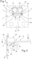
Figure 1 is a frontal view of an object-hanging device coupled with a support wall provided with suitable holes that is the subject-matter of the present invention; -
Figure 2 shows a side view of the device offigure 1 ; -
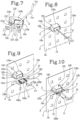
Figures 3, 4, 5, 6 ,7, 8, 9 and 10 are views of the consecutive passages of the coupling and decoupling of the device shown infigures 1 with and from the support wall; -
Figure 11 is a view illustrating in a detailed frontal view the main component of the fixing body comprised in the device shown infigure 1 . -
Figure 12 is a view illustrating an oblique top view of the main component of the fixing body shown infigures 11 . -
Figure 13 is a view illustrating an oblique bottom view of the main component of the fixing body shown infigures 11 and 12 ; -
Figure 14 is a view illustrating in a detailed bottom view the main component of the fixing body comprised in the device shown infigure 1 ; -
Figure 15 is a view illustrating an oblique top view of the support component of the fixing body shown infigure 14 . - With reference to the appended
figures, 1 denotes an object-hanging device intended to be coupled reversibly with asupport wall 2 with a vertical extension and equipped with suitable throughholes 3. - The
support wall 2 can be of any type present in the prior art. Thewall 2 shows afrontal surface 2a and arear surface 2b. - The term "frontal" means the surface arranged opposite an observer, i.e. directly in view relative to the point of view of the observer.
- The
wall 2 can have a thickness of different values, but this thickness is preferably constant along the entire body of thewall 2. Theholes 3 can have different geometries and dimensions, preferably with a square or rectangular geometry and dimensions compatible with other fixing devices present in the prior art, having still more preferably a horizontal and/or vertical dimension comprised between 5 mm and 50 mm. Theholes 3 are preferably arranged reciprocally vertically and/or horizontally at fixed distances, constituting regular vertical and/or horizontal series that therefore define a matrix of holes that is distributed regularly on thewall 2. - The device 1 is intended to support an external object (not shown) suspended along the
wall 2, in particular exerting a constraining reaction opposing the weight force "P" of the object. - The device 1 comprises a
support body 10 and a fixingbody 100. - The
support body 10 and the fixingbody 100 can consist of different, preferably rigid, materials with great mechanical resistance to stress. Coupling with the wall can comprise a direct contact with thewall 2 or by means of coatings affecting the contact zones of the fixingbody 100 or of thesupport wall 10 with the wall, which are preferably rough and/or rubberized, to improve the stability of the contact with thewall 2. - The
support body 10 comprises afirst portion 11 configured to make a rest and/or a stop for the external object to be hung along thewall 2 and a second portion configured to make a reversible connection between thesupport body 10 and thesupport wall 2. - In particular, the
first portion 11 can comprise sections of different geometry, selected according to the type of object to be supported. Advantageously, the geometry of thefirst portion 11 can allow great flexibility of use of the object-hanging device 1, which can accordingly support objects of different shapes and/or dimensions. - The
first portion 11 can be arranged cantilevered on thefrontal surface 2a of thewall 2, perpendicularly or askew relative to thefrontal surface 2a of thewall 2 in function of the type of external object to be supported. - Preferably, the
first portion 11 has a geometry that is more developed along the longitudinal dimension than over the other dimensions. - The longitudinal geometry can be respectively at least partially linear or broken or curved.
- The
first portion 11 has two ends, afirst end 11a of which is preferably free and dedicated to engaging with the external object whilst asecond end 11b is arranged near or adhering to thefrontal surface 2a of thewall 2. - According to the embodiment illustrated into the present figures, the
first portion 11 extends along a longitudinal axis "S" thereof, in a substantially linear manner, and has afirst end 11a and asecond end 11b preferably provided with respective transverse elements. The transverse elements are opposite one another relative to the longitudinal axis "S". - Preferably, a first
transverse element 11c is arranged along thefirst end 11a and is dedicated to engaging with the external object and a secondtransverse element 11d is arranged along thesecond end 11b and is adapted to form an auxiliary support rest 6 against thefrontal surface 2a of thewall 2. The presence of thetransverse elements transverse element 11d and the support rest 6 deriving therefrom may be necessary if the weight of the body to be maintained suspended may cause involuntary bending of thesupport body 10. - The
second portion 12 is at least partially inserted between at least one of the throughholes 3 so as to define anchoring of thesupport body 10 to thewall 2. When the device 1 is in a use configuration, thesecond portion 12 engages with therear surface 2b of thewall 2, having at least onerest 4 on therear surface 2b. In particular, thesecond portion 12 has afirst sub-portion 12a intended to remain at least partially inside thehole 3, arranged or suspended through thehole 3 or resting on aninner surface 5 of thehole 3. - Further, the
second portion 12 has asecond sub-portion 12b intended to form therest 4 on therear surface 2b of thewall 2. This second sub-portion 12b is arranged preferably transversely with respect to thefirst sub-portion 12a and along therear surface 2b of thewall 2. - The sub-portion 12b can have different geometric shapes so as to constitute different types of
rest 4 like, for example, a point-like, linear or surface rest. Preferably, both thefirst portion 11, comprising the firsttransverse element 11c and the secondtransverse element 11d, and thesecond portion 12, comprising thefirst sub-portion 12a and thesecond sub-portion 12b, can be made into separable and reciprocally assemblable modules. This separation into modules can apply to one or more of the elements constituting thesupport body 10. - Alternatively, the different elements disclosed above that constitute the
support body 10 can be made "in a single piece". - The fixing
body 100 can be reversibly engaged with thefirst portion 11 and/or with thesecond portion 12 when the object-hanging device 1 is in a use configuration. The fixingbody 100 exerts a first thrust action "A" and a second thrust action "B", opposite the first thrust action "A", respectively acting on thefirst portion 11, and/or on thesecond portion 12, and on thewall 2 so as to define stable anchoring of thesupport body 10 on thewall 2. In the embodiment illustrated in the appended figures, the fixingbody 100 is arranged along thefrontal surface 2a of thewall 2, engaging respectively with thesupport body 10, and in particular with thefirst section 11 and/or with thesecond section 12, and thefrontal surface 2a. - The fixing
body 100 thus exerts thrust action "B" on thefrontal surface 2a of thewall 2. Therest 4 on the other hand helps couple the device 1 with thewall 2, by means of a thrust action "C" on therear surface 2b of thewall 2. As this thrust action "C" opposes the action "B", the device 1 performs a "gripping" action relative to thewall 2. - If the second
transverse element 11d is present, thetransverse element 11d exerts a further thrust action "D" on thefrontal surface 2a of thewall 2 opposing the weight "P" of the external object engaged on the device 1. - Preferably, this transverse element is oriented to the floor where the support wall rests, exerting the thrust action "D" in an area on the
frontal surface 2a of the wall arranged below theholes 3 receiving thesecond sub-portion 12b so as to provide support from below to thesupport body 10. - In the embodiment illustrated in the appended figures, the fixing
body 100 is so constituted as to comprise at least onefirst seat 101 suitable for receiving at least one longitudinal portion of thefirst portion 11 of thesupport body 10. Thisseat 101 can be so engaged as to engage thefirst portion 11 and/or thesupport body 100. - This engagement can be inside the fixing
body 100 or, alternatively, outside, so as to solidly anchor thefirst portion 11 to thesupport body 100 by means of suitable connecting members and to avoid involuntary shifts of the first portion relative to thesupport body 100 and, consequently, relative to thewall 2. - The fixing
body 100 is also configured prevent rotation of thesupport body 10 relative to thewall 2. - With reference to the appended figures, the fixing body can comprise a
main component 110, suitable for exerting the first thrust action "A" and the second thrust action "B", and asupport component 120, reversibly connected to themain component 110 and suitable for preventing rotation of thesupport body 10, in particular around the extension axis "S" of thesupport body 10. Themain component 110 can be used operationally autonomously or in conjunction with thesupport component 120. - In particular, in the embodiment of the appended figures, the
main component 110 is defined preferably by a polyhedral geometry, preferably a prismatic geometry, even more preferably a six-face geometry arranged in a reciprocally orthogonal manner. For example, in the appended figures themain component 110 has a substantially cuboid conformation. In other embodiments that are not illustrated, the main component can have other geometries. - In particular, the
main component 110 comprises anupper face 110a and alower face 110b arranged preferably parallel to the floor on which thesupport wall 2 is arranged, two side faces 110c and 110d preferably parallel, afrontal face 110e and a rear face 110f preferably parallel to thefrontal surface 2a of thewall 2. The rear face 110f is adapted to be arranged adhering to thewall 2, and in particular to thefrontal surface 2a so as to apply the thrust action "B" preferably in an extended manner against thefrontal surface 2a of thewall 2. - The
main component 110 defines thefirst seat 101, adapted to receive thefirst portion 11 of thesupport body 10, as a channel arranged along thelower face 110b of themain component 110, compatible in form with thesupport body 10 and of the arrangement thereof relative to thefrontal surface 2a of thewall 2. - Preferably, the
main component 110 can be hollow internally so as to require, advantageously, less material for its manufacture and to be lighter. Thesupport component 120 is made in polyhedral form, substantially with six reciprocally orthogonal sides, and more precisely as a plate, comprising anupper side 120a and alower side 120b that are substantially more extensive than the remaining sides and are arranged parallel to the floor, twolateral sides frontal side 120e and arear side 120f. - The
support component 120 is couplable with themain component 110 by means of suitable connecting members, in particular having theupper face 120a reversibly connectable to thelower face 110b of themain component 110. - In this embodiment, the connecting members of the
main component 110 comprise at least twohooks lower face 110, and with respective facing cavities, and adapted to slidingly receive between them thesupport component 120, which is provided in turn with two suitable slidingguides lateral sides support component 120 is inserted frontally, i.e. with thefrontal side 120e facing the observer and therear side 120f facing thefrontal surface 2a of the wall relative to themain component 110, preferably until therear side 120f adheres to thefrontal surface 2a of thewall 2. - Once the
support component 120 is connected to themain component 110, it exerts a fixing action by mechanical interference on thefirst portion 11 of thesupport body 10, preventing the latter from being subjected to rotational stress around the axis "S". - In the presence of the second
transverse element 11d, thesupport component 120 defines asecond seat 122 that is suitable for receiving the secondtransverse element 11d, to ensure simultaneously both translational and rotational anchoring of thesupport body 10 relative to thewall 2. In particular, thissecond seat 122 is in a channel that is compatible in shape with the secondtransverse element 11d and arranged on therear face 120f of thesupport component 120. The arrangement enables the secondtransverse element 11d to be secured against both rotational and translational stresses, being in further assistance to thefirst portion 11 immune to rotations in relation to the "S" axis. - Preferably, and as for example shown in the appended figures, the
support body 10 further comprises athird portion 13, defined between thefirst portion 11 and thesecond portion 12, defining a housing 14, for or a coupling element with, the fixingbody 100. - Preferably, the fixing
body 100 is at least partially inserted into the housing 14. - Preferably, the housing 14 has a geometry that is such as to be compatible in form with the fixing
body 100, in other words so that the fixing body fills the housing 14 totally. - Preferably, the
first portion 11 and/or thesecond portion 12 and/or thethird portion 13 are made in the form of thread-like elements. - In the embodiment of the appended figures, the
first portion 11, thesecond portion 12 and thethird portion 13 are made in the form of thread-like elements. - Different embodiments can provide for each of these elements having different geometries, for example "I" or "L" or "V" or "C" or "U" or "M" geometries.
- In the embodiment of the appended figures, the
second portion 12 is made "as one piece" with thethird portion 13 so as to define a fork geometry. - Preferably, the
second portion 12 defines at least one tine of the fork geometry. - In other words, the
third portion 13 is substantially linear and arranged transversely to thesecond portion 12. - With reference to the appended figures, the
second portion 12 defines two tines. For each tine, there is acorresponding sub-portion 12a, insertable singly into acorresponding hole 3 on thefrontal surface 2a and asecond sub-portion 12b, being like a natural extension of thefirst sub-portion 12a and forming acorresponding rest 4. - The housing 14 is preferably defined as a planar substantially rectangular shape, comprised between the
third portion 13 and thefrontal surface 2a of thewall 2 where the fixingbody 100 is partially inserted from above, or is inserted from thelower surface 110b. - In this arrangement, the thrust action "B" is exerted on a zone of the
frontal surface 2a of thewall 2. Therest 4 helps anchor the device 1 on thewall 2, by means of a thrust action "C" on therear surface 2b of thewall 2. - The
second sub-portion 12b of thesecond portion 12 is oriented so as to obtain therest 4 in an area arranged above thehole 3 traversed by thesub-portion 12a. The thrust "C" and the thrust "B" are symmetrical so that they form a grip around thewall 2. - By inserting the fixing
body 100, or possibly themain component 110 from above, thefirst seat 101 is made to rest on the first portion of thesupport body 11 and couple therewith. - Preferably, the fixing
body 100, or possibly themain component 110, comprises at least partially along the lateral perimeter, in other words at least along thefrontal face 110e and/or the side faces 110c and 110e, achannel 112 suitable for receiving thethird portion 13 of thesupport body 10, when the fixingbody 100 is inserted into the housing 14 so as to exert retaining by mechanical interference. - Observing
figures 6 or7 , the fixing body is inserted inside the housing 14 by first resting thefrontal face 110e and the fixing body on thethird portion 13, so that thethird portion 13 engages with thechannel 112. Subsequently, by means of rotation, all the perimeter of the fixingbody 100 is engaged inside the housing 14 and the main component is engaged by means of mechanical interference with thefrontal surface 2a of thewall 2. - In the embodiment illustrated in the appended figures, the fixing
body 100, or possibly themain component 110, exerts the thrust action "A" also at least partially on thethird portion 13. - Further, the fixing
body 100, or possibly themain component 110, exerts a lateral thrust action "E" on thethird portion 13, exerting anchoring that is free of possible lateral translations of thesupport body 10 and, consequently, of the device 1 relative to thewall 2. - In this embodiment, the
third portion 13 and thefirst portion 11 are separate entities, which are reversibly connectable by mechanical interference. The fixingbody 100 is thus further configured to maintain thethird portion 13 and thefirst portion 11 coupled, helping in this mechanical interference. Alternatively, thethird portion 13 and thefirst portion 11 can be made "of one piece". In the circumstances in which thesupport body 10 provides for the use of transverse elements, thethird portion 13 defines a housing 14 in which at least one of the transverse elements is at least partially inserted inside the housing 14. In the embodiment of the appended figures, the secondtransverse element 11d, resting on thefrontal surface 2a of thewall 2, is inserted into the housing 14 defined by thethird portion 13. Thesecond seat 122, arranged on thesupport component 120, is suitable for coupling through shape coupling with the secondtransverse element 11d to fix stably thetransverse element 11d to thewall 2 and prevent rotating and/or translating against thewall 2, and accordingly also rotating around the "S" of thesupport body 10. - With reference to
figures 10 and15 , thesupport component 120 comprises afirst slit 123a and asecond slit 123b arranged opposite near the lateral sides 120c and 120d. - This first and second slit define near
lateral sides first fin 124a and asecond fin 124b, configured to be flexibly deformable with respect to thesupport component 120. - The fins are configured to engage with and disengage from the cavities defined respectively by the
hooks - The first and the
second slit guides - Preferably, the first and the
second slit support component 120. - The
support fins hooks support component 120 to be fixed in position relative to themain component 110. - The
fins hooks - The lateral fins (124a, 124b) are flexibly deformable relative to the support component (120) so as to engage, in use, the lateral fins (124a, 124b) with the main component (110) and enable the lateral fins (12a, 124b) to disengage from the main component (110).
- In other words, the
first fin 124a and thesecond fin 124b are movable in relation to one another so as to reduce a distance therebetween so as to permit the fins to pass through the cavities defined by thehooks - Preferably, said disengagement occurs by means of a manual compression action "F" of the
fins fins hooks - Therefore, a pressure exerted by a user (i.e. the aforesaid manual compression action "F") enables this distance between the
fins support component 120 can be inserted or extracted to engage with or disengage from themain component 110. - In other words, during engagement of the
support component 120 with themain component 110, thefirst fin 124a and thesecond fin 124b are moved away from one another so as to define interference with thehooks support component 120 from themain component 110. - Advantageously, this configuration permits an engagement and a disengagement that are easily actuatable by the
support component 120 relative to themain component 110 whereas it simultaneously stabilises in position the main component and, in turn, thesupport body 10. - The device 1 can comprise auxiliary elements adapted to improve the arrangement and the support of the external body with or on the
support body 10. Such auxiliary elements can comprise a rounded portion suitably arranged on thefirst portion 11, and in particular on thefirst end 11a or of the firsttransverse element 11c. This rounded portion comprises a cross section above the cross section of thefirst end 11a or of the firsttransverse element 11c so as to improve retaining of the external body and prevent an involuntary disengagement of the external body from the device 1. - This rounded portion can be integrated with the
first portion 11 or be integratable as anaccessory body 15. - Other alternative auxiliary elements that are integrated or are integratable with the
first portion 11 of thesupport body 10 can comprise auxiliary bodies provided with coupling holes or auxiliary bodies provided with grippers. - Further, the device 1 can also be employed by means of interposing a container that is clad on the
first portion 11 and hanging on saidwall 2. - Advantageously, the device 1 is capable of overcoming the drawbacks which have emerged from the prior art.
- Advantageously, using a device 1 comprising a
support body 10 and a fixingbody 100 that is reversibly engageable with thesupport body 10 permits reversible coupling with thesupport wall 2, anyway ensuring that the device 1 is stably anchored on the wall and is not subjected to involuntary movements, whether in the event of impacts or of vibrations. - Advantageously, the above device 1 is easy to install and uninstall.
- Further, the device 1 is realizable easily and economically.
- Further, the device 1 is easily reusable to support objects having different shapes, dimensions and functions.
Claims (15)
- An object-hanging device (1), intended to couple reversibly with a support wall (2) with a vertical extension and equipped with suitable through holes (3), wherein said device (1) comprises:- a support body (10) comprising,- a first portion (11) configured to make a rest element and/or a stop for an object;- a second portion (12) configured to make a reversible connection between said support body (10) and said support wall (2);- a fixing body (100) reversibly engageable or engaged with said first portion (11) and/or with said second portion (12) in a use configuration of said object-hanging device (1), wherein said second portion (12) is at least partially inserted inside at least one of said holes (3) so as to define the anchoring of said support body (10) on said wall (2);wherein said fixing body (100), in said use configuration, exerts a first thrust action (A) and a second thrust action (B), opposite said first thrust action (A), respectively acting on said first portion (11) and/or on said second portion (12), and on said wall (2) so as to define stable anchoring of said support body (10) on said wall (2).
- The device (1) according to claim 1, wherein said fixing body (100), in said use configuration, is further configured to prevent rotation of said support body (10).
- The device (1) according to claim 1 or 2, wherein said fixing body (100) comprises a main component (110), suitable for exerting said first thrust action (A) and said second thrust action (B), and a support component (120) reversibly connected to said main component (110).
- The device (1) according to claim 2 and 3, wherein said support component (120) is suitable for preventing rotation of said support body (10).
- The device (1) according to one or more of the preceding claims, wherein said support body (10) comprises a third portion (13), defined between said first portion (11) and said second portion (12), defining a housing (14) for, or an element for coupling with, said fixing body (100).
- The device (1) according to claim 5, wherein said second portion (12) is made in a single piece with said third portion (13) so as to define a fork geometry, wherein at least said second portion (12) defines at least one tine of said fork geometry.
- The device (1) according to claim 5 or 6, wherein said third portion (13) defines a housing (14) for said fixing body (100) and wherein said fixing body (100) comprises at least partially along the perimeter a channel (112) adapted to receive said third portion (13) of said support body (10).
- The device (1) according to one or more of claims 5 to 7, wherein said first portion (11) and/or said second portion (12) and/or said third portion (13) are made in the form of threadlike elements having an "I" or an "L" or a "V" or a "C" or a "U" or an "M"-shaped geometry.
- The device (1) according to one or more of claims 5 to 8, wherein said third portion (13) and said first portion (11) are reversibly connectable by mechanical interference, and wherein said fixing body (100) is further configured to maintain said mechanical interference between the third portion (13) and the first portion (11).
- The device (1) according to one or more of the preceding claims, wherein said first portion (11) extends along a longitudinal axis (S) thereof and has a first end (11a) and a second end (11b) provided with respective transverse elements (11c and 11d), said transverse elements (11c and 11d), being opposite one another relative to said longitudinal axis (S).
- The device (1) according to claim 10, wherein said fixing body (100) comprises at least a first seat (101) suitable for receiving a longitudinal portion of said first portion (11) of the support body (10).
- The device according to claim 11 when dependent on claim 3, wherein said main component defines said first seat (101) and wherein said support component (120) defines a second seat (122) that is suitable for receiving one of said transverse elements (11d).
- The device according to one or more of claims 10 to 12 when dependent on claim 5, wherein said third portion (13) defines a housing (14) and wherein at least one of said transverse elements (11d) is at least partially inserted inside said housing (100).
- The device according to claim 3, wherein the support component is couplable with said principal component (110) by suitable connecting members, said connecting members comprising:- at least two "C"-shaped hooks (111a and 111b), arranged on the main component (110) and with respective facing cavities;- two sliding guides (121a and 121b), arranged correspondingly along two lateral sides (120c and 120d) of said support component (120);wherein said hooks (111a and 111b) are adapted to slidingly receive between them the support component (120) and realise a connection therewith by mechanical interference.
- The device according to claim 14, wherein the support component (120) comprises a first slit (123a) and a second slit (123b) defining a first lateral fin (124a) and a second lateral fin (124b) that are arranged respectively near said lateral sides (120e and 120d),
said lateral fins (124a, 124b) being flexibly deformable relative to said support component (120) so as to realise, in use, an engagement of the lateral fins (124a, 124b) with the main component (110) and permit disengagement of the lateral fins (124a, 124b) from the main component (110).
Applications Claiming Priority (1)
| Application Number | Priority Date | Filing Date | Title |
|---|---|---|---|
| IT102022000026955A IT202200026955A1 (en) | 2022-12-28 | 2022-12-28 | Object-hanging device |
Publications (2)
| Publication Number | Publication Date |
|---|---|
| EP4394190A1 true EP4394190A1 (en) | 2024-07-03 |
| EP4394190B1 EP4394190B1 (en) | 2026-03-11 |
Family
ID=85556433
Family Applications (1)
| Application Number | Title | Priority Date | Filing Date |
|---|---|---|---|
| EP23217593.5A Active EP4394190B1 (en) | 2022-12-28 | 2023-12-18 | Object-hanging device |
Country Status (4)
| Country | Link |
|---|---|
| US (1) | US12414641B2 (en) |
| EP (1) | EP4394190B1 (en) |
| AR (1) | AR131511A1 (en) |
| IT (1) | IT202200026955A1 (en) |
Citations (2)
| Publication number | Priority date | Publication date | Assignee | Title |
|---|---|---|---|---|
| US4258892A (en) * | 1978-07-24 | 1981-03-31 | Advertising Metal Display Company | Peg hook display supporting apparatus |
| US10827853B2 (en) * | 2018-03-26 | 2020-11-10 | Delta Lock Company, LLC | Locking devices for pegboard hooks, slatwall hooks, and crossbar hooks |
Family Cites Families (7)
| Publication number | Priority date | Publication date | Assignee | Title |
|---|---|---|---|---|
| US3715096A (en) * | 1971-06-18 | 1973-02-06 | W Filbert | Article support |
| US4289242A (en) * | 1979-08-31 | 1981-09-15 | Kenyon David L | Display security device |
| US5180128A (en) * | 1991-09-17 | 1993-01-19 | Massey Richard C | Pegboard hook mounting assembly |
| US6694654B2 (en) * | 2002-06-12 | 2004-02-24 | American Gasket Technologies, Inc. | Display tag holder |
| US7178678B2 (en) * | 2003-08-06 | 2007-02-20 | Alpha Security Products, Inc. | Merchandise display hook |
| US20090049723A1 (en) * | 2007-08-22 | 2009-02-26 | Mechtronics Corporation | Product display designator |
| US20090173853A1 (en) * | 2008-01-07 | 2009-07-09 | Invue Security Products, Inc. | Universal mounting bracket for merchandise display hooks |
-
2022
- 2022-12-28 IT IT102022000026955A patent/IT202200026955A1/en unknown
-
2023
- 2023-12-18 EP EP23217593.5A patent/EP4394190B1/en active Active
- 2023-12-20 US US18/390,843 patent/US12414641B2/en active Active
- 2023-12-27 AR ARP230103554A patent/AR131511A1/en unknown
Patent Citations (2)
| Publication number | Priority date | Publication date | Assignee | Title |
|---|---|---|---|---|
| US4258892A (en) * | 1978-07-24 | 1981-03-31 | Advertising Metal Display Company | Peg hook display supporting apparatus |
| US10827853B2 (en) * | 2018-03-26 | 2020-11-10 | Delta Lock Company, LLC | Locking devices for pegboard hooks, slatwall hooks, and crossbar hooks |
Also Published As
| Publication number | Publication date |
|---|---|
| IT202200026955A1 (en) | 2024-06-28 |
| US12414641B2 (en) | 2025-09-16 |
| EP4394190B1 (en) | 2026-03-11 |
| AR131511A1 (en) | 2025-03-26 |
| US20240215739A1 (en) | 2024-07-04 |
Similar Documents
| Publication | Publication Date | Title |
|---|---|---|
| CA2708466C (en) | Mount with separate device interface | |
| US5906350A (en) | Wrench suspension rack | |
| US5499724A (en) | Wall mounted tool rack for the storage of hand tools | |
| US5897002A (en) | Tool hanging rack | |
| US7694925B2 (en) | Storage systems having storage accessory with locking tab | |
| CN109906044B (en) | hanger for display floor mats | |
| US6231018B1 (en) | Guitar hanger | |
| US4768660A (en) | Adjustable hook and mounting rail assembly | |
| US6695276B2 (en) | Wall hanger assembly | |
| US20070102381A1 (en) | Tool box fastening device for fastening a tool box set to a vertical wall | |
| US12049758B1 (en) | Apparatus and method for hanging architectural panels with concealed attachment points | |
| US20250261755A1 (en) | Wall and ceiling track system for mounting devices | |
| US4645154A (en) | Retaining clip for peg board hook | |
| EP4394190B1 (en) | Object-hanging device | |
| US4534529A (en) | Shelf bracket and cooperable locking bracket retainer | |
| US12460669B2 (en) | Mounting device to securely hang a wide range of objects to a wall | |
| GB2248764A (en) | Locking wall accessory fastener | |
| US7121031B2 (en) | Hangtag with tool securing mechanism | |
| US4609172A (en) | Shelf bracket and cooperable locking bracket retainer | |
| US7556235B1 (en) | Earthquake proof picture hanging system | |
| JPH0865867A (en) | Suspension fitting | |
| EP0384654B1 (en) | Multi-purpose canister wall bracket | |
| JPH0542766Y2 (en) | ||
| JPH0615065Y2 (en) | Hanging tool | |
| GB2253256A (en) | Connector system for store fixtures. |
Legal Events
| Date | Code | Title | Description |
|---|---|---|---|
| PUAI | Public reference made under article 153(3) epc to a published international application that has entered the european phase |
Free format text: ORIGINAL CODE: 0009012 |
|
| STAA | Information on the status of an ep patent application or granted ep patent |
Free format text: STATUS: THE APPLICATION HAS BEEN PUBLISHED |
|
| AK | Designated contracting states |
Kind code of ref document: A1 Designated state(s): AL AT BE BG CH CY CZ DE DK EE ES FI FR GB GR HR HU IE IS IT LI LT LU LV MC ME MK MT NL NO PL PT RO RS SE SI SK SM TR |
|
| STAA | Information on the status of an ep patent application or granted ep patent |
Free format text: STATUS: REQUEST FOR EXAMINATION WAS MADE |
|
| 17P | Request for examination filed |
Effective date: 20241016 |
|
| RBV | Designated contracting states (corrected) |
Designated state(s): AL AT BE BG CH CY CZ DE DK EE ES FI FR GB GR HR HU IE IS IT LI LT LU LV MC ME MK MT NL NO PL PT RO RS SE SI SK SM TR |
|
| P01 | Opt-out of the competence of the unified patent court (upc) registered |
Free format text: CASE NUMBER: APP_67473/2024 Effective date: 20241220 |
|
| GRAP | Despatch of communication of intention to grant a patent |
Free format text: ORIGINAL CODE: EPIDOSNIGR1 |
|
| STAA | Information on the status of an ep patent application or granted ep patent |
Free format text: STATUS: GRANT OF PATENT IS INTENDED |
|
| INTG | Intention to grant announced |
Effective date: 20260102 |
|
| GRAS | Grant fee paid |
Free format text: ORIGINAL CODE: EPIDOSNIGR3 |
|
| GRAA | (expected) grant |
Free format text: ORIGINAL CODE: 0009210 |
|
| STAA | Information on the status of an ep patent application or granted ep patent |
Free format text: STATUS: THE PATENT HAS BEEN GRANTED |
|
| AK | Designated contracting states |
Kind code of ref document: B1 Designated state(s): AL AT BE BG CH CY CZ DE DK EE ES FI FR GB GR HR HU IE IS IT LI LT LU LV MC ME MK MT NL NO PL PT RO RS SE SI SK SM TR |
|
| REG | Reference to a national code |
Ref country code: CH Ref legal event code: F10 Free format text: ST27 STATUS EVENT CODE: U-0-0-F10-F00 (AS PROVIDED BY THE NATIONAL OFFICE) Effective date: 20260311 Ref country code: GB Ref legal event code: FG4D |
|
| REG | Reference to a national code |
Ref country code: CH Ref legal event code: R17 Free format text: ST27 STATUS EVENT CODE: U-0-0-R10-R17 (AS PROVIDED BY THE NATIONAL OFFICE) Effective date: 20260316 |
|
| REG | Reference to a national code |
Ref country code: DE Ref legal event code: R096 Ref document number: 602023013313 Country of ref document: DE |
|
| REG | Reference to a national code |
Ref country code: IE Ref legal event code: FG4D |
|
| REG | Reference to a national code |
Ref country code: NL Ref legal event code: FP |