EP4394166A1 - Control method and system for electric power of steam turbine generator of nuclear power plant - Google Patents
Control method and system for electric power of steam turbine generator of nuclear power plant Download PDFInfo
- Publication number
- EP4394166A1 EP4394166A1 EP23854254.2A EP23854254A EP4394166A1 EP 4394166 A1 EP4394166 A1 EP 4394166A1 EP 23854254 A EP23854254 A EP 23854254A EP 4394166 A1 EP4394166 A1 EP 4394166A1
- Authority
- EP
- European Patent Office
- Prior art keywords
- time
- electric power
- real
- thermal power
- input terminal
- Prior art date
- Legal status (The legal status is an assumption and is not a legal conclusion. Google has not performed a legal analysis and makes no representation as to the accuracy of the status listed.)
- Granted
Links
Images



Classifications
-
- F—MECHANICAL ENGINEERING; LIGHTING; HEATING; WEAPONS; BLASTING
- F01—MACHINES OR ENGINES IN GENERAL; ENGINE PLANTS IN GENERAL; STEAM ENGINES
- F01D—NON-POSITIVE DISPLACEMENT MACHINES OR ENGINES, e.g. STEAM TURBINES
- F01D21/00—Shutting-down of machines or engines, e.g. in emergency; Regulating, controlling, or safety means not otherwise provided for
- F01D21/12—Shutting-down of machines or engines, e.g. in emergency; Regulating, controlling, or safety means not otherwise provided for responsive to temperature
-
- F—MECHANICAL ENGINEERING; LIGHTING; HEATING; WEAPONS; BLASTING
- F01—MACHINES OR ENGINES IN GENERAL; ENGINE PLANTS IN GENERAL; STEAM ENGINES
- F01K—STEAM ENGINE PLANTS; STEAM ACCUMULATORS; ENGINE PLANTS NOT OTHERWISE PROVIDED FOR; ENGINES USING SPECIAL WORKING FLUIDS OR CYCLES
- F01K13/00—General layout or general methods of operation of complete plants
- F01K13/02—Controlling, e.g. stopping or starting
-
- F—MECHANICAL ENGINEERING; LIGHTING; HEATING; WEAPONS; BLASTING
- F22—STEAM GENERATION
- F22B—METHODS OF STEAM GENERATION; STEAM BOILERS
- F22B35/00—Control systems for steam boilers
- F22B35/004—Control systems for steam generators of nuclear power plants
-
- G—PHYSICS
- G21—NUCLEAR PHYSICS; NUCLEAR ENGINEERING
- G21D—NUCLEAR POWER PLANT
- G21D3/00—Control of nuclear power plant
- G21D3/001—Computer implemented control
-
- G—PHYSICS
- G21—NUCLEAR PHYSICS; NUCLEAR ENGINEERING
- G21D—NUCLEAR POWER PLANT
- G21D3/00—Control of nuclear power plant
- G21D3/08—Regulation of any parameters in the plant
-
- Y—GENERAL TAGGING OF NEW TECHNOLOGICAL DEVELOPMENTS; GENERAL TAGGING OF CROSS-SECTIONAL TECHNOLOGIES SPANNING OVER SEVERAL SECTIONS OF THE IPC; TECHNICAL SUBJECTS COVERED BY FORMER USPC CROSS-REFERENCE ART COLLECTIONS [XRACs] AND DIGESTS
- Y02—TECHNOLOGIES OR APPLICATIONS FOR MITIGATION OR ADAPTATION AGAINST CLIMATE CHANGE
- Y02E—REDUCTION OF GREENHOUSE GAS [GHG] EMISSIONS, RELATED TO ENERGY GENERATION, TRANSMISSION OR DISTRIBUTION
- Y02E30/00—Energy generation of nuclear origin
Definitions
- the thermal efficiency of the unit changes in real time (such as low seawater temperature and high thermal efficiency, whereas low thermal efficiency); because the electric power is controlled by closed loop, the real-time thermal power of primary loop will increase correspondingly when the thermal efficiency decreases, and the real-time thermal power of primary loop will decrease correspondingly when the thermal efficiency increases, which leads to the change of real-time thermal power of primary loop and real-time moving thermal power (real-time moving thermal power refers to the average value of real-time thermal power of primary loop of nuclear power plant in any continuous set time).
- the technical problem to be solved by the invention is at least one defect existing in the prior art, the invention provides a control method and system for an electric power of a steam turbine generator of a nuclear power plant.
- the technical proposal adopted by the invention for solving the technical problem is that a control method for an electric power of a steam turbine generator of a nuclear power plant is constructed, which comprises the following steps:
- Z m is the predicted calorific value
- P 0 is the preset target average thermal power
- P m-1 is the real-time moving thermal power
- T is the first set time
- X m is the front-end actual calorific value.
- the S50 further comprises:
- S50 it also comprises: Limiting an upper limit value and a lower limit value of the electric power setting value according to a thermal efficiency factor and the preset target average thermal power.
- P smin is the lower limit value of the electric power setting value
- function min is the function for taking the minimum value
- k n is the thermal efficiency factor obtained by current calculation
- k n-1 is the thermal efficiency factor obtained by last calculation
- H3 is the maximum value of preset real-time thermal power
- P 0 is the preset target average thermal power
- C is the preset real-time thermal power adjustment amount
- P smax is the upper limit value of the electric power setting value
- max is a function taking a maximum value.
- the S50 further comprises: Sending the electric power setting value to a power controller of the steam turbine generator based on a setting period; wherein, the setting period is equal to a second set time.
- the S50 further comprises: Determining whether the real-time moving thermal power exceeds a preset overshoot band; if so, setting the setting period to one-half of the second set time; otherwise, setting the setting period to the second set time.
- the magnitude of the preset overshoot band is 1MW.
- control method for an electric power of a steam turbine generator of a nuclear power plant further comprises: S11, invalidating the electric power setting value and reducing the thermal power of the primary loop immediately, when the accumulative time of the real-time thermal power longer than a preset early warning value exceeds a preset early warning time in the first set time.
- the invention also constructs an control system for an electric power of a steam turbine generator of a nuclear power plant, comprising:
- the second operation unit comprises a first moving average module, a first multiplier, a second multiplier and a first subtractor;
- x1 ⁇ t 0 t 3 P t ⁇ dt ⁇ ⁇ t 1 t 3 P t ⁇ dt ;
- the preset warning time corresponds to 60 minutes.
- the first operation unit 2 comprises a third moving average module, an input of the third moving average module is connected to the thermal power acquisition unit 1 to receive real-time thermal power, and a period setting terminal of the third moving average module for receiving a first set time.
- a fourth operation unit 5 performs conversion and efficiency correction operation based on the predicted calorific value to output an electric power setting value for controlling the electric power of the steam turbine generator.
- the non-inverting input terminal of the third comparator 81 is connected with the thermal power acquisition unit 1 to receive real-time thermal power
- the inverting input terminal of the third comparator 81 is used to receive the preset warning value
- the output terminal of the third comparator 81 is connected with the first input terminal of the counting module 83
- the enabling terminal of the fourth pulse module 82 is used to receive a high level
- the period setting terminal of the fourth pulse module 82 is used to receive the first set time
- the output terminal of the fourth pulse module 82 is connected with the second input terminal of the counting module 83
- the output terminal of the counting module 83 is connected with the non-inverting input terminal of the fourth comparator 84 and the first selection input terminal of the second selection module 85
- the inverting input terminal of the fourth comparator 84 is connected with the output terminal of the second selection module 85
- the output terminal of the second selection module 85 is connected to the emergency thermal power reduction unit 7 as the cumulative time output terminal.
- Embodiments in this specification are described in a progressive manner and each embodiment focuses on differences from other embodiments. Same and similar parts between the embodiments can be referred to each other.
- the apparatus disclosed in the embodiment since it corresponds to the method disclosed in the embodiment, the description is relatively simple, and the relevant parts can be described in the method section.
Landscapes
- Engineering & Computer Science (AREA)
- General Engineering & Computer Science (AREA)
- Physics & Mathematics (AREA)
- Mechanical Engineering (AREA)
- Chemical & Material Sciences (AREA)
- Combustion & Propulsion (AREA)
- Plasma & Fusion (AREA)
- High Energy & Nuclear Physics (AREA)
- Thermal Sciences (AREA)
- Control Of Turbines (AREA)
- Control Of Eletrric Generators (AREA)
- Feedback Control In General (AREA)
Abstract
Description
- The invention relates to the technical field of nuclear power instrument control, in particular to a control method and system for an electric power of a steam turbine generator of a nuclear power plant.
- For the current nuclear power plant, when the electric power of steam turbine generator is given, the thermal efficiency of the unit changes in real time (such as low seawater temperature and high thermal efficiency, whereas low thermal efficiency); because the electric power is controlled by closed loop, the real-time thermal power of primary loop will increase correspondingly when the thermal efficiency decreases, and the real-time thermal power of primary loop will decrease correspondingly when the thermal efficiency increases, which leads to the change of real-time thermal power of primary loop and real-time moving thermal power (real-time moving thermal power refers to the average value of real-time thermal power of primary loop of nuclear power plant in any continuous set time). In order to avoid the operation of nuclear power plant beyond the technical specifications, the operator must appropriately reduce the electric power setting value to leave a certain margin for the thermal power of the primary loop; At the same time, after the thermal efficiency becomes higher (margin becomes larger), the operator will appropriately increase the electric power setting value to improve the economy. This will have two consequences: 1. during a day, the operator needs to manually adjust the electric power setting value many times; 2. the thermal power margin of the primary loop is not effectively utilized, which leads to the poor economy. It has been proved that it is extremely difficult to use traditional PID control on the premise that the cumulative time of real-time thermal power overrun within 8 hours does not exceed the time limit, the real-time moving thermal power within 8 hours does not exceed the time limit, the action times of the actuator are few, and the thermal power margin is fully utilized to improve the economy.
- The technical problem to be solved by the invention is at least one defect existing in the prior art, the invention provides a control method and system for an electric power of a steam turbine generator of a nuclear power plant.
- The technical proposal adopted by the invention for solving the technical problem is that a control method for an electric power of a steam turbine generator of a nuclear power plant is constructed, which comprises the following steps:
- S10, collecting a real-time thermal power of the primary loop in a nuclear power plant;
- S20, calculating a real-time moving thermal power of the real-time thermal power in a first set time based on a moving average method;
- S30, performing front-end calorific value calculation process according to the real-time moving thermal power and the real-time thermal power to obtain a front-end actual calorific value;
- S40, performing calorific value prediction operation according to a preset target average thermal power, the real-time moving thermal power and the front-end actual calorific value to obtain a predicted calorific value;
- S50, performing conversion and efficiency correction operations based on the predicted calorific value , and obtaining an electric power setting value for controlling the electric power of the steam turbine generator and then returning to S10.
- Preferably, in S30, the front-end calorific value calculation process comprises:
- S301, calculating a second moving thermal power of the real-time thermal power in a third set time based on a moving average method; wherein the third set time is equal to a difference of the first set time minus a second set time;
- S302, multiplying the real-time moving thermal power by the first set time to obtain a first calorific value;
- S303, multiplying the second moving thermal power by the third set time to obtain a second calorific value;
- S304, subtracting the second calorific value from the first calorific value to obtain the front-end actual calorific value.
- Preferably, in S40, the expression of the predicted calorific value is:

- Wherein Zm is the predicted calorific value,
P0 is the preset target average thermal power,Pm-1 is the real-time moving thermal power, T is the first set time, and Xm is the front-end actual calorific value. - Preferably, in S50, the expression of the electric power setting value is:

- Wherein, Ps is the electric power setting value, Zm is the predicted calorific value, △t is a second set time, and k is a thermal efficiency factor.
- Preferably, the S50 further comprises:
- acquiring the real-time electric power of the steam turbine generator;
- Performing division operation on the data at the same time in the real-time thermal power and the real-time electric power to obtain proportional data;
- Calculating a moving proportion coefficient of the proportion data in the second set time based on a moving average method, and the moving proportion coefficient is the thermal efficiency factor.
- Preferably, in S50, it also comprises:
Limiting an upper limit value and a lower limit value of the electric power setting value according to a thermal efficiency factor and the preset target average thermal power. - Preferably, the lower limit value of the electric power setting value is expressed as:

Wherein, Psmin is the lower limit value of the electric power setting value, function min is the function for taking the minimum value, kn is the thermal efficiency factor obtained by current calculation, kn-1 is the thermal efficiency factor obtained by last calculation, H3 is the maximum value of preset real-time thermal power,P0 is the preset target average thermal power, and C is the preset real-time thermal power adjustment amount;
The expression of the upper limit value of the electric power setting value is:

Wherein, Psmax is the upper limit value of the electric power setting value, and max is a function taking a maximum value. - Preferably, the S50 further comprises:
Sending the electric power setting value to a power controller of the steam turbine generator based on a setting period; wherein, the setting period is equal to a second set time. - Preferably, the S50 further comprises:
Determining whether the real-time moving thermal power exceeds a preset overshoot band; if so, setting the setting period to one-half of the second set time; otherwise, setting the setting period to the second set time. - Preferably, in S50, the magnitude of the preset overshoot band is 1MW.
- Preferably, the control method for an electric power of a steam turbine generator of a nuclear power plant further comprises:
S11, invalidating the electric power setting value and reducing the thermal power of the primary loop immediately, when the accumulative time of the real-time thermal power longer than a preset early warning value exceeds a preset early warning time in the first set time. - The invention also constructs an control system for an electric power of a steam turbine generator of a nuclear power plant, comprising:
- A thermal power acquisition unit, which is used for acquiring real-time thermal power of the primary loop in a nuclear power plant;
- A first operation unit, which is used for calculating a real-time moving thermal power of the real-time thermal power in a first set time based on a moving average method;
- A second operation unit, which is used for calculating the front-end calorific value of the real-time moving thermal power and the real-time thermal power to output a front-end actual calorific value;
- A third operation unit, which is used for performing calorific value prediction operation according to a preset target average thermal power, the real-time moving thermal power and the front-end actual calorific value to output a predicted calorific value; the predicted calorific value is used to characterize the actual calorific value required by the steam turbine generator for a second set time thereafter;
- A fourth operation unit, which is used for performing conversion and efficiency correction operation based on the predicted calorific value to output an electric power setting value for controlling the electric power of the steam turbine generator.
- Preferably, the second operation unit comprises a first moving average module, a first multiplier, a second multiplier and a first subtractor;
- The input terminal of the first moving average module is connected with the thermal power acquisition unit to receive the real-time thermal power, the period setting terminal of the first moving average module is used to receive a third set time, and the output terminal of the first moving average module outputs a second moving thermal power; Wherein the third set time is equal to a difference of the first set time minus the second set time;
- The first input terminal of the first multiplier is connected with the first operation unit, and the second input terminal of the first multiplier is used for receiving the first set time;
- The input terminal of the second multiplier is connected with the output terminal of the first moving average module, and the second input terminal of the second multiplier is used for receiving the third set time;
- The minuend input terminal of the first subtractor is connected with the output terminal of the first multiplier, the subtrahend input terminal of the first subtractor is connected with the output terminal of the second multiplier, and the output terminal of the first subtractor outputs the front-end actual calorific value.
- Preferably, the third operation unit comprises a second subtractor, a third multiplier and a first adder;
- The minuend input terminal of the second subtractor is used for receiving the preset target average thermal power, and the subtrahend input terminal of the second subtractor is connected with the first operation unit;
- The first input terminal of the third multiplier is connected with the output terminal of the second subtractor, and the second input terminal of the third multiplier is used for receiving the first set time;
- The first input terminal of the first adder is connected with the output terminal of the third multiplier, the second input terminal of the first adder is connected with the second operation unit to receive the front-end actual calorific value, and the output terminal of the first adder outputs the predicted calorific value.
- Preferably, the fourth operation unit comprises a first divider, an efficiency correction unit and a fourth multiplier;
- The dividend input terminal of the first divider is connected with the third operation unit to receive the predicted calorific value, and the divisor input terminal of the first divider is used to receive a second set time;
- The first input terminal of the fourth multiplier is connected with the output terminal of the first divider, the second input terminal of the fourth multiplier is connected with the efficiency correction unit to receive the thermal efficiency factor output by the efficiency correction unit, and the output terminal of the fourth multiplier outputs the electric power setting value.
- Preferably, the efficiency correction unit comprises an electric power acquisition unit, a second divider and a second moving average module;
- The electric power acquisition unit is used for collecting the real-time electric power of the steam turbine generator;
- The dividend input terminal of the second divider is connected with the electric power acquisition unit to receive the real-time electric power, and the divisor input terminal of the second divider is connected with the thermal power acquisition unit to receive the real-time thermal power;
- The input terminal of the second moving average module is connected with the output terminal of the second divider, the period setting terminal of the second moving average module is used for receiving the second set time, and the output terminal of the second moving average module outputs the thermal efficiency factor.
- Preferably, the control system for an electric power of a steam turbine generator of a nuclear power plant further comprises: a timing setting unit;
The timing setting unit is used for sending the electric power setting value to a power controller of the steam turbine generator based on a setting period. - Preferably, the timing setting unit comprises an instruction unit and a first selection module;
- When the real-time moving thermal power does not exceed a preset overshoot band, the instruction unit outputs a selection instruction every time after the third set time and lasts for a certain time; when the real-time moving thermal power exceeds the preset overshoot band, the selection instruction is output every time after a fifth set time and lasts for a certain time; wherein the fifth set time is equal to one-half of the third set time;
- The first selection input of the first selection module is connected with the fourth operation unit to receive the electric power setting value, the second selection input of the first selection module is connected with the output of the first selection module, the output of the first selection module can be connected with the power controller of the steam turbine generator, and the selection terminal of the first selection module is connected with the instruction unit to receive the selection instruction.
- Preferably, the instruction unit comprises a first comparator, a second comparator, a first OR gate, a NOT gate, an AND gate, a second OR gate, a first pulse module, a second pulse module and a third pulse module;
- The non-inverting input terminal of the first comparator is connected with the first operation unit to receive the real-time moving thermal power, and the inverting input terminal of the first comparator is used to receive the upper limit value of the preset overshoot band;
- The non-inverting input terminal of the second comparator is used for receiving the lower limit value of the preset overshoot band, and the inverting input terminal of the second comparator is connected with the first operation unit to receive the real-time moving thermal power;
- The first input terminal of the first OR gate is connected to the output terminal of the first comparator, the second input terminal of the first OR gate is connected to the output terminal of the second comparator, the output terminal of the first OR gate is connected to the first input terminal of the AND gate through the NOT gate;
- The enabling terminal of the first pulse module is used for receiving a high level, the period setting terminal of the first pulse module is used for receiving the second set time, the output terminal of the first pulse module is connected with the second input terminal of the AND gate, and the output terminal of the AND gate is connected with the first input terminal of the second OR gate;
- The enabling terminal of the second pulse module is connected with the output terminal of the first comparator, the period setting terminal of the second pulse module is used for receiving the fifth set time, and the output terminal of the second pulse module is connected with the second input terminal of the second OR gate;
- The enabling terminal of the third pulse module is connected with the output terminal of the second comparator, the period setting terminal of the third pulse module is used for receiving the fifth set time, and the output terminal of the third pulse module is connected with the third input terminal of the second OR gate;
- The output terminal of the second OR gate outputs the selection instruction.
- Preferably, the control system for an electric power of a steam turbine generator of a nuclear power plant further comprises: an emergency thermal power reduction unit;
- The emergency thermal power reduction unit is used for outputting an emergency stop and temperature reduction instruction for invalidating the electric power setting value and reducing the thermal power of the primary loop when the accumulated time of the real-time thermal power longer than a preset early warning value exceeds a preset early warning time in the first set time.
- Preferably, the control system for an electric power of a steam turbine generator of a nuclear power plant, further comprises a timing unit, which comprising a third comparator, a fourth pulse module, a counting module, a fourth comparator and a second selection module;
- The non-inverting input terminal of the third comparator is connected with the thermal power acquisition unit to receive real-time thermal power, the inverting input terminal of the third comparator is used to receive a preset early warning value, the output terminal of the third comparator is connected with the first input terminal of the counting module, the enabling terminal of the fourth pulse module is used for receiving a high level, the period setting terminal of the fourth pulse module is used for receiving the first set time, the output terminal of the fourth pulse module is connected with the second input terminal of the counting module, the output terminal of the counting module is connected with the non-inverting input terminal of the fourth comparator and the first selection input terminal of the second selection module, the inverting input terminal of the fourth comparator is connected with the output terminal of the second selection module; The output terminal of the fourth comparator is connected with the selection terminal of the second selection module, the second selection input terminal of the second selection module is connected with the output terminal of the second selection module, and the output terminal of the second selection module is connected with the emergency thermal power reduction unit as an accumulative time output terminal.
- The invention has at least the following beneficial effects: providing a control method and system for an electric power of a steam turbine generator of a nuclear power plant. The method comprises the following steps: S10, collecting a real-time thermal power of the primary loop in a nuclear power plant; S20, calculating a real-time moving thermal power of the real-time thermal power in a first set time based on the moving average method; S30, performing front-end calorific value calculation process according to the real-time moving thermal power and the real-time thermal power to obtain a front-end actual calorific value; S40, performing calorific value prediction operation according to a preset target average thermal power, real-time moving thermal power and front-end actual calorific value to obtain predicted calorific value; S50, performing conversion and efficiency correction operation based on the predicted calorific value, and obtaining an electric power setting value for controlling the electric power of the steam turbine generator, and returned to S10. The implementation of the invention can effectively increase the power generation efficiency of the nuclear power plant, improve the economic benefit of the nuclear power plant, change the original manual control of the operator into automatic adjustment on the premise of meeting the technical specification of the nuclear power plant operation, reduce the work burden of the operator, greatly reduce the risk of exceeding the technical specification caused by the operator frequently manually adjusting the electric power setting value, greatly reduce the action times of the executive mechanism, reduce the mechanical wear of the executive mechanism, and play an active role in improving the equipment life and stability of the unit.
- Brief description of that drawing the invention will now be further described by way of embodiment with reference to the accompany drawings in which:
-
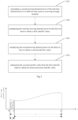
Fig. 1 is a flowchart of a control method for an electric power of a steam turbine generator of a nuclear power plant provided by the present invention; -
Fig. 2 is a flowchart of step S30 in the a control method for an electric power of a steam turbine generator of a nuclear power plant provided by the present invention; -
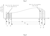
Fig. 3 is an example of real-time thermal power acquisition curve of the primary loop provided by the present invention; -
Fig. 4 is an example of real-time thermal power acquisition curve of the primary loop provided by the present invention; -
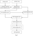
Fig. 5 is a first structural schematic diagram of a control system for an electric power of a steam turbine generator of a nuclear power plant provided by the present invention. -
Fig. 6 is a second structure schematic diagram of a control system for an electric power of a steam turbine generator of a nuclear power plant provided by the present invention; -
Fig. 7 is the third structure schematic diagram of a control system for an electric power of a steam turbine generator of a nuclear power plant provided by the present invention; -
Fig. 8 is a structural schematic diagram of a timing unit in a control system for an electric power of a steam turbine generator of a nuclear power plant provided by the present invention. - In order to have a clearer understanding of the technical features, objects and effects of the invention, particular embodiments of the invention are described in detail with reference to the accompanying drawings.
- Referring to
Fig. 1 , the present invention provides a control method for a control method for a control method for a control method and system for an electric power of a steam turbine generator of a nuclear power plant. The control method comprises steps S10, S20, S30, S40 and S50. - Step S10 comprises: collecting a real-time thermal power of the primary loop in a nuclear power plant. It should be noted that the real-time thermal power comprises power value and collecting time, so as to prepare for the subsequent steps.
- Step S20 comprises: calculating the real-time moving thermal power of the real-time thermal power in a first set time based on a moving average method.
- Specifically, by executing step S20, the average value of the real-time thermal power of the primary loop from the time before the first set time to the moment can be obtained. It should be noted that, in principle, the shorter the first set time, it is beneficial to accurately monitor the real-time thermal power of the primary loop and play a positive role in improving the control accuracy of the electric power of the steam turbine generator, but it will cause the equipment to lose and age faster. Therefore, the first set time needs to be set according to the equipment performance and state of the nuclear power plant. In some embodiments, the first set time may be 8 hours.
- Step S30 comprises the following steps: performing front-end calorific value calculation processing to the real-time moving thermal power and the real-time thermal power to obtain front-end actual calorific value; the front-end actual calorific value is used to characterize the total heat generated by the primary loop from the start time of the first set time to a second set time.
- Specifically, because the real-time moving thermal power is calculated based on the moving average method, the longer the distance from the acquisition time, the real-time thermal power will be squeezed out first, that is to say, the front-end actual calorific value corresponds to the part of heat that will be pushed out for the second set time.
- In some embodiments, as shown in
Fig. 2 , in Step S30, the front-end calorific value calculation process comprises Step S301, Step S302, Step S303, and Step S304. - Step S301 comprises: calculating a second moving thermal power of the real-time thermal power in a third set time based on a moving average method; wherein the third set time is equal to the difference between the first set time and the second set time.
- Step S302 comprises: multiplying the real-time moving thermal power by the first set time to obtain a first calorific value.
- Step S303 comprises: multiplying a second moving thermal power by a third set time to obtain a second calorific value.
- Step S304 comprises: subtracting the second calorific value from the first calorific value to obtain the front-end actual calorific value.
- Specifically, as shown in
fig. 3 , the calculation principle of steps S301 to S304 is as follows: executing step S301 is equivalent to calculating the average value of real-time thermal power of the primary loop from the third set time to the present moment (i.e. t1-t3). Executing step S303 is equivalent to calculating the total calorific value X (i.e. the first calorific value) of the primary loop in the previous first set time (i.e. t0-t3).Executing step S303 corresponds to calculating the calorific value Y (second calorific value) of the primary loop in the previous third set time (i.e. t1-t3). Since the third set time is equal to the difference of the first set time minus the second set time, the calorific value obtained by subtracting the second calorific value from the first set time is equivalent to the total heat Z (front-end actual calorific value) generated by the primary loop from the start time of the first set time to the second set time (i.e., t0-t1). - Step S40 comprises: performing calorific value prediction operation according to the preset target average thermal power, the real-time moving thermal power and the front-end actual calorific value to obtain the predicted calorific value. The predicted calorific value is used to characterize the actual calorific value required by the steam turbine generator for a second set time thereafter;
Fig. 4 shows the real-time thermal power acquisition curve of the primary loop of a certain unit. Referring tofig. 4 , it is assumed that the preset target average thermal power isP0 , the first set time is T and Pt is real-time thermal power measurement function, so we can get: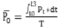
- For a first set time period (t0-t3) that has occurred, the total thermal power of a second set time period (t0-t1) to be extruded out is x1, and x1 can be calculated in combination with the collected real-time thermal power:

- For the next impending first set time (t1-t4), the corresponding real-time moving thermal power is
P1 , and the following results are obtained:
- For a second set time period (t3-t4) to be entered, the target total heat is z1, and if
P1 =P0 , z1=x1. Although a time period (t3-t4) to be entered will be controlled with z1 as the target value, due to the influence of the change of thermal efficiency of the unit, the actual total thermal power of the time period (t3-t4) is y1, and z1 and y1 are not necessarily equal, which leads toP1 andP0 are not necessarily equal. The real-time moving thermal power corresponding to the next set time period (t2-t5) to be entered isP2 . To makeP1 =P0 , z2 should be controlled as the target value in the second set time period (t4-t5) to be entered, and the following results are obtained:P0 * T =P1 * T - x2 + z2; Therefore, the formula (1) can be obtained by conversion:
- Furthermore, assuming that the corresponding real-time moving thermal power for any first set time is
Pm , and to makePm =Po , for a second set time period to be entered, combined with formula (1), the expression of predicted calorific value can be deduced as follows:

Where Zm is a predicted calorific value,P0 is a preset target average thermal power,Pm-1 is a real-time moving thermal power, T is a first set time, and Xm is a front-end actual calorific value. - Step S50 comprises: performing conversion and efficiency correction operations based on the predicted calorific value, obtaining an electric power setting value for controlling the electric power of the steam turbine generator, and returning to step S10. Specifically, the purpose of conversion and efficiency correction operation is: firstly, the predicted calorific value is converted to obtain the basic value for controlling the electric power of steam turbine generator, and then the basic value is corrected, so as to eliminate the influence of thermal efficiency on the accuracy of electric power control of steam turbine generator as much as possible.
- In some embodiments, the expression for the electrical power setting is:
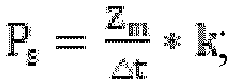
- Wherein, Ps is an electric power setting value, Zm is a predicted calorific value, △t is a second set time, and k is a thermal efficiency factor.
- Further, in some embodiments, Step S50 also comprises a calculation method of the thermal efficiency factor, which accurately obtains the thermal efficiency factor by real-time monitoring the variation rule of the real-time electric power and the real-time thermal power of the steam turbine generator, specifically comprising: firstly, collecting the real-time electric power of the steam turbine generator. Then, the data of real-time thermal power and real-time electric power at the same time are divided to obtain proportional data. Finally, based on the moving average method, a moving proportion coefficient of the proportion data in a second set time is calculated, and the moving proportion coefficient is set as a thermal efficiency factor.
- In order to avoid oscillation of the electric power setting value, and when the oscillation magnitude is likely to increase, the preset target average thermal power remains constant, in some examples, step S50 further comprises limiting the upper and lower limits of the electric power setting value according to the thermal efficiency factor and the preset target average thermal power after calculating the electric power setting value.
- Further, in some embodiments, the upper limit value of the electric power setting value may be calculated by the following expression:

- Wherein, Psmax is the lower limit value of the electric power setting value. The function min is the function for taking the minimum value, that is, the function min is used to output the smaller value of H3 and (
P0 + C); kn is the thermal efficiency factor currently calculated; kn-1 is the thermal efficiency factor obtained from the previous calculation; H3 is the preset real-time thermal power maximum value, which can be set by the staff;P 0 is the average thermal power of the target; C is the preset real-time thermal power adjustment amount, which can be set by the staff. - Further, in some embodiments, the lower limit value of the electric power setting value may be calculated by the following expression:

- Where Psmin is the lower limit of the electric power setting value; max is a function that takes the maximum value, that is, the function min is used to output the larger value of kn and kn-1.
- It should be noted that, the thermal efficiency factor is calculated based on the moving average method, and it is a value that changes with the change of the working process of the steam turbine generator, so the upper limit value and the lower limit value of the electric power setting value also change dynamically, and the setting principle of the upper limit value and the lower limit value of the electric power setting value is to make the electric power setting value closer to the preset target average thermal power and avoid the loss of control of the electric power setting value.
- In some embodiments, step S50 further comprises: sending the electrical power setting value to the power controller of the steam turbine generator based on the set period to reduce the number of actuator actions or adjustments caused when the steam turbine generator performs electrical power adjustment, thereby reducing mechanical wear of these actuators and playing a positive role in improving the equipment life and stability of the unit. In this embodiment, the setting period is equal to the first set time.
- In order to avoid thermal efficiency reduction between the primary loop and the steam turbine generator due to the real-time moving thermal power overshoot, in some embodiments, step S50 further comprises: determining whether the real-time moving thermal power exceeds the preset overshoot band, if so, setting the set period to one-half of the second set time, otherwise setting the set period to the second set time. The purpose of step S50 is to shorten the setting period, thereby improving the response speed of the electric power control loop and making the real-time moving thermal power return to the preset overshoot band as soon as possible. It will be understood that the set period will be set to a second set time when the real-time moving thermal power does not exceed the preset overshoot band.
- Optional, the magnitude of the preset overshoot band is 1MW.
- In some embodiments, the control method for an electric power of a steam turbine generator of a nuclear power plant further comprises the following steps: Step S11: If the cumulative duration of the real-time thermal power greater than the preset warning value in the first set time exceeds the preset warning time, invalidating the electric power setting value and reducing the thermal power of the primary loop immediately. Specifically, when the step S11 is executed, the real-time thermal power over-limit accumulative time in the first set time can be avoided, and the electric power setting value is invalidated, so that the real-time thermal power is increased or the accumulative time is continuously prolonged due to the adjustment of the electric power setting value, so as to avoid the long-time overload operation of the primary loop and the unexpected failure of the primary loop, thereby improving the stability and safety of the unit.
- Optional, when the preset warning value is set to 1.0017 times of the rated power value, the preset warning time corresponds to 60 minutes.
- Referring to
Fig. 5 , the invention also provides a control system for an electric power of a steam turbine generator of a nuclear power plant comprising a thermalpower acquisition unit 1, afirst operation unit 2, asecond operation unit 3, athird operation unit 4 and afourth operation unit 5. - The thermal
power acquisition unit 1 is used for collecting the real-time thermal power of the primary loop in a nuclear power plant. Specifically, the thermalpower acquisition unit 1 can be a functional module for collecting real-time thermal power in the primary loop monitoring system of the nuclear power plant. - The
first operation unit 2 is used for calculating the real-time moving thermal power of the real-time thermal power in the first set time based on a moving average method. - In some embodiments, the
first operation unit 2 comprises a third moving average module, an input of the third moving average module is connected to the thermalpower acquisition unit 1 to receive real-time thermal power, and a period setting terminal of the third moving average module for receiving a first set time. - The
second operation unit 3 is used for calculating the front-end calorific value of the real-time moving thermal power and the real-time thermal power to output the front-end actual calorific value; The front-end actual calorific value is used to characterize the total heat generated by the primary loop from the start time of the first set time to the second set time. - In some embodiments, as shown in
fig. 6 , thesecond operation unit 3 comprises a first movingaverage module 31, a first multiplier 32, asecond multiplier 33, and afirst subtractor 34; - Specifically, the input terminal of the first moving
average module 31 is connected with the thermalpower acquisition unit 1 to receive real-time thermal power, the period setting terminal of the first movingaverage module 31 is used to receive a third set time, and the output terminal of the first movingaverage module 31 outputs a second moving thermal power; Wherein, the third set time is equal to the difference between the first set time and the second set time; - The first input terminal of the first multiplier 32 is connected with the
first operation unit 2, and the second input terminal of the first multiplier 32 is used for receiving the first set time; - The input terminal of the
second multiplier 33 is connected with the output terminal of the first movingaverage module 31, and the second input terminal of thesecond multiplier 33 is used for receiving the third set time; - The minuend input terminal of the
first subtractor 34 is connected to the output terminal of the first multiplier 32, the subtrahend input terminal of thefirst subtractor 34 is connected to the output terminal of thesecond multiplier 33, and the output terminal of thefirst subtractor 34 outputs the front-end actual calorific value. - The
third operation unit 4 is used for performing calorific value prediction operation according to the preset target average thermal power, the real-time moving thermal power and the front-end actual calorific value to output the predicted calorific value. The predicted calorific value is used to characterize the actual calorific value required by the steam turbine generator for a second set time thereafter. - In some embodiments as shown in
fig. 6 , thethird operation unit 4 comprises asecond subtractor 41, athird multiplier 42 and afirst adder 43; - Specifically, the minuend input terminal of the
second subtractor 41 is used for receiving the preset target average thermal power, and the subtrahend input terminal of thesecond subtractor 41 is connected with thefirst operation unit 2; - The first input terminal of the
third multiplier 42 is connected to the output terminal of thesecond subtractor 41, and the second input terminal of thethird multiplier 42 is used for receiving the first set time; - The first input terminal of the
first adder 43 is connected to the output terminal of thethird multiplier 42, the second input terminal of thefirst adder 43 is connected to thesecond operation unit 3 to receive the front-end actual calorific value, and the output terminal of thefirst adder 43 outputs the predicted calorific value. - A
fourth operation unit 5 performs conversion and efficiency correction operation based on the predicted calorific value to output an electric power setting value for controlling the electric power of the steam turbine generator. - In some embodiments as shown in
fig. 6 , thefourth operation unit 5 comprises a first divider 51, anefficiency correction unit 52 and afourth multiplier 53; - The dividend input of the first divider 51 is connected to the
third operation unit 4 to receive the predicted calorific value, and the divisor input of the first divider 51 is used to receive the second set time; - A first input terminal of the
fourth multiplier 53 is connected to an output terminal of the first divider 51, a second input terminal of thefourth multiplier 53 is connected to theefficiency correction unit 52 to receive a thermal efficiency factor output from theefficiency correction unit 52, and an output terminal of thefourth multiplier 53 outputs an electric power setting value. - In some examples as shown in
Fig. 6 , theefficiency correction unit 52 comprises an electricpower acquisition unit 521, asecond divider 522 and a second movingaverage module 523; - Specifically, the electric
power acquisition unit 521 is used for a acquiring real-time electric power of the steam turbine generator; - The dividend input of the
second divider 522 is connected to the electricpower acquisition unit 521 to receive real-time electric power, and the divisor input of thesecond divider 522 is connected to a thermalpower acquisition unit 1 to receive real-time thermal power; - The input terminal of the second moving
average module 523 is connected with the output terminal of thesecond divider 522, the period setting terminal of the second movingaverage module 523 is used for receiving the second set time, and the output terminal of the second movingaverage module 523 outputs the thermal efficiency factor. - In some examples, as shown in
fig. 5 , the control system for an electric power of a steam turbine generator of a nuclear power plant further comprises: atiming setting unit 6; thetiming setting unit 6 is used for sending the electric power setting value to the power controller of the steam turbine generator based on the setting period. - In some examples as shown in
fig. 6 , thetiming setting unit 6 comprises aninstruction unit 61 and afirst selection module 62; - Specifically, when the real-time moving thermal power does not exceed the preset overshoot band, the
instruction unit 61 outputs a selection instruction every time after a third set time and lasts for a certain time; When the real-time moving thermal power exceeds the preset overshoot band, the selection instruction is output every time after a fifth set time and lasts for a certain time; Wherein, the fifth set time is equal to one-half of the third set time; - The first selection input of the
first selection module 62 is connected to thefourth operation unit 5 to receive the electric power setting value, the second selection input of thefirst selection module 62 is connected to the output of thefirst selection module 62, the output of thefirst selection module 62 can be connected to the power controller of a steam turbine generator, and the selection terminal of thefirst selection module 62 is connected to theinstruction unit 61 to receive a selection instruction. - In some examples, as shown in
fig. 7 , theinstruction unit 61 comprises afirst comparator 621, asecond comparator 622, a first ORgate 623, aNOT gate 624, an ANDgate 625, a second ORgate 626, afirst pulse module 627, asecond pulse module 628, and athird pulse module 629; - Specifically, the non-inverting input terminal of the
first comparator 621 is connected to thefirst operation unit 2 to receive the real-time moving thermal power, and the inverting input terminal of thefirst comparator 621 is used to receive the upper limit value of the preset overshoot band; - The non-inverting input terminal of the
second comparator 622 is used for receiving the lower limit value of the preset overshoot band, and the inverting input terminal of thesecond comparator 622 is connected with thefirst operation unit 2 to receive the real-time moving thermal power; - The first input of a first OR
gate 623 is connected to the output of thefirst comparator 621, the second input of the first ORgate 623 is connected to the output of thesecond comparator 622, and the output of the first ORgate 623 is connected to the first input of the ANDgate 625 through theNOT gate 624; - The enabling terminal of the
first pulse module 627 is used for receiving a high level, the period setting terminal of thefirst pulse module 627 is used for receiving a second set time, the output terminal of thefirst pulse module 627 is connected to the second input terminal of the ANDgate 625, and the output terminal of the ANDgate 625 is connected to the first input terminal of the second ORgate 626; - The enabling terminal of the
second pulse module 628 is connected to the output terminal of thefirst comparator 621, the period setting terminal of thesecond pulse module 628 is used for receiving the fifth set time, and the output terminal of thesecond pulse module 628 is connected to the second input terminal of the second ORgate 626; - The enabling terminal of the
third pulse module 629 is connected to the output terminal of thesecond comparator 622, the period setting terminal of thethird pulse module 629 is used for receiving the fifth set time, and the output terminal of thethird pulse module 629 is connected to the third input terminal of the second ORgate 626; - The output of the second OR
gate 626 outputs a selection instruction. - In some examples, as shown in
fig. 5 , the acontrol system for an electric power of a steam turbine generator of a nuclear power plant further comprises: an emergency thermalpower reduction unit 7. Specifically, the emergency thermalpower reduction unit 7 is used for outputting an emergency stop and temperature reduction instruction for invalidating the electric power setting value and reducing the thermal power of the primary loop when the accumulated time when the real-time thermal power is greater than the set warning value in the first set time exceeds the set warning time. - In some embodiments, as shown in
Fig. 4 , the a control system for an electric power of a steam turbine generator of a nuclear power plant further comprises a timing unit 8.Thetiming unit 8 is connected with the emergency thermalpower reduction unit 7, and is used for calculating the cumulative time when the real-time thermal power is greater than the set warning value. - Further in some embodiments as shown in
fig. 8 thetiming unit 8 comprises athird comparator 81, afourth pulse module 82, acounting module 83, afourth comparator 84 and asecond selection module 85. - Specifically, the non-inverting input terminal of the
third comparator 81 is connected with the thermalpower acquisition unit 1 to receive real-time thermal power, the inverting input terminal of thethird comparator 81 is used to receive the preset warning value, the output terminal of thethird comparator 81 is connected with the first input terminal of thecounting module 83, the enabling terminal of thefourth pulse module 82 is used to receive a high level, the period setting terminal of thefourth pulse module 82 is used to receive the first set time, the output terminal of thefourth pulse module 82 is connected with the second input terminal of thecounting module 83, the output terminal of thecounting module 83 is connected with the non-inverting input terminal of thefourth comparator 84 and the first selection input terminal of thesecond selection module 85, the inverting input terminal of thefourth comparator 84 is connected with the output terminal of thesecond selection module 85, and the output terminal of thesecond selection module 85 is connected to the emergency thermalpower reduction unit 7 as the cumulative time output terminal. - It should be noted that the working principle of the moving average module (including the first, second and third moving average modules) is to take the time input at the period setting end as the moving period, carry out moving average operation on the input data at the input terminal, and finally output the average value at its output terminal. For example, the input data of two consecutive cycles are 1, 2, 3 and 4 in turn, and the number of input data in each cycle is 3. The output value obtained by moving average operation in the first cycle is (1 +2 +3) /3=2. Similarly, the output value obtained in the next cycle is (2 +3 +4) /3=3.
- The working principle of the selection module (including the first and second selection modules) is as follows: when the selection terminal of the selection module is true (high level), the output terminal of the selection module outputs the value of the first selection input terminal; When the selection terminal of the selection module is false (low level), the output terminal of the selection module outputs the value of its second selection input terminal.
- The working principle of the pulse module (including the first, second and third pulse modules) is as follows: when the enabling terminal of the pulse module is true (high level), the pulse signal with a fixed length (1 second) is output according to the time period input by the period setting terminal; When the enabling terminal of the pulse module is false (low level), the pulse module does not generate a pulse signal.
- The working principle of the counting module is as follows: when the second input terminal of the counting module is false (low level), if the first input terminal of the counting module is true (high level), the counting module increases every 1 second from 0, if the first input terminal of the counting module is false (low level), the counting module stops increasing and maintains the counting at the previous moment; When the second input terminal is true (high level), the output terminal of the calculation module is reset to 0.
- Understandably, the implementation of the invention can effectively increase the power generation efficiency of the nuclear power plant, improve the economic benefits of the nuclear power plant, change the original manual control of the operator into automatic adjustment on the premise of meeting the technical specifications for the operation of the nuclear power plant, reduce the work burden of the operator, greatly reduce the risk of exceeding the technical specifications caused by the frequent manual adjustment of the electric power setting value by the operator, greatly reduce the action times of the executive mechanism, reduce the mechanical wear of the executive mechanism, and play an active role in improving the equipment life and stability of the unit.
- Embodiments in this specification are described in a progressive manner and each embodiment focuses on differences from other embodiments. Same and similar parts between the embodiments can be referred to each other. As for the apparatus disclosed in the embodiment, since it corresponds to the method disclosed in the embodiment, the description is relatively simple, and the relevant parts can be described in the method section.
- Skilled artisans may further appreciate that the elements and algorithmic steps of each example described in connection with the embodiments disclosed herein can be implemented in electronic hardware, computer software, or a combination of both, and the composition and steps of each example have been described functionally generally in the above description in order to clearly illustrate interchangeability of hardware and software. Whether these functions are performed in hardware or software depends on the specific application and design constraints of the technical scheme. Skilled artisans may use different methods for each particular application to implement the described functionality but such implementation should not be considered outside the scope of the present invention.
- The steps of the method or algorithm described in connection with the embodiments disclosed herein may be implemented directly in hardware, a software module executed by a processor, or a combination of both. The software module may be placed in random access memory (RAM), memory, read only memory (ROM), electrically programmable ROM, electrically erasable programmable ROM, registers, hard disk, removable disk, CD-ROM, or any other form of storage medium known in the art.
- It is to be understood that the above embodiments are expressed only as preferred embodiments of the present invention and the description thereof is more specific and detailed but is not therefore to be construed as limiting the scope of the invention patent; It should be pointed out that, for those of ordinary skill in the art, the above technical features can be freely combined without departing from the concept of the invention, and a number of modifications and improvements can be made, all of which belong to the protection scope of the invention; Therefore, all equivalent transformations and modifications made with the scope of the claims of the present invention should fall within the scope of the claims of the present invention.
Claims (21)
- A control method for an electric power of a steam turbine generator of a nuclear power plant, wherein, comprising the steps of:S10, collecting real-time thermal power of the primary loop in a nuclear power plant;S20, calculating the real-time moving thermal power of the real-time thermal power within a first set time based on a moving average method;S30, performing front-end calorific value calculation process according to the real-time moving thermal power and the real-time thermal power to obtain front-end actual calorific value;S40, performing calorific value prediction operation according to a preset target average thermal power, the real-time moving thermal power and the front-end actual calorific value to obtain a predicted calorific value;and S50, performing conversion and efficiency correction calculation based on the predicted calorific value to obtain an electric power setting value for controlling the electric power of the steam turbine generator, and returning to S10.
- The control method for an electric power of a steam turbine generator of a nuclear power plant according to claim 1, wherein in S30, the front-end calorific value calculation process comprises:S301: calculating a second moving thermal power of the real-time thermal power within a third set time based on a moving average method, wherein the third set time is equal to a difference of the first set time minus a second set time;S302, multiplying the real-time moving thermal power by the first set time to obtain a first calorific value;S303: multiplying the second moving thermal power by the third set time to obtain a second calorific value;S304: subtracting the second calorific value from the first calorific value to obtain the front-end actual calorific value.
- The control method for an electric power of a steam turbine generator of a nuclear power plant according to claim 2, wherein in S40, the expression of the predicted calorific value is:

P0 is the preset target average thermal power, Pm-1 is the real-time moving thermal power, T is the first set time, and Xm is the front-end actual calorific value. - The control method for an electric power of a steam turbine generator of a nuclear power plant according to claim 1, wherein in S50, the expression of the electric power setting value is:

- The control method for an electric power of a steam turbine generator of a nuclear power plant according to claim 4, wherein S50 further comprises:acquiring the real-time electric power of the steam turbine generator;performing division operation on the data at the same moment in the real-time thermal power and the real-time electric power to obtain proportion data;calculating a moving proportion coefficient of the proportion data in the second set time based on a moving average method, and the moving proportion coefficient being the thermal efficiency factor.
- The control method for an electric power of a steam turbine generator of a nuclear power plant according to claim 5, wherein the step S50 further comprises:
limiting an upper limit value and a lower limit value of the electric power setting value according to a thermal efficiency factor and the preset target average thermal power. - The control method for an electric power of a steam turbine generator of a nuclear power plant according to claim 6, wherein the lower limit value of the electric power setting value is expressed by:
 wherein, Psmin is the lower limit value of the electric power setting value, function min is the function for taking the minimum value, kn is the thermal efficiency factor obtained by current calculation, kn-1 is the thermal efficiency factor obtained by last calculation, H3 is the maximum value of preset real-time thermal power,
P0 is the preset target average thermal power, and C is a preset real-time thermal power regulation amount;the expression of the upper limit value of the electric power setting value is: wherein, Psmax is the upper limit value of the electric power setting value, and the max is a function of taking a maximum value.
 - The control method for an electric power of a steam turbine generator of a nuclear power plant according to claim 1, wherein the step S50 further comprises: p
sending the electric power setting value to a power controller of the steam turbine generator based on a setting period; wherein the setting period is equal to a second set time. - The control method for an electric power of a steam turbine generator of a nuclear power plant according to claim 8, wherein S50 further comprises:
determining whether the real-time moving thermal power exceeds a preset overshoot band, if so, setting the setting period to be one half of the second set time, otherwise, setting the setting period to be the second set time. - The control method for an electric power of a steam turbine generator of a nuclear power plant according to claim 9, wherein in S50, the magnitude of the preset overshoot band is 1 MW.
- The control method for an electric power of a steam turbine generator of a nuclear power plant according to claim 1, further comprising:
S11, invalidating the electric power setting value and reducing the thermal power of the primary loop immediately, when the accumulative time of the real-time thermal power longer than a preset early warning value exceeds a preset early warning time in the first set time. - A control system for an electric power of a steam turbine generator of a nuclear power plant, wherein, comprising:a thermal power acquisition unit (1),which is used for acquiring the real-time thermal power of the primary loop in a nuclear power plant;a first operation unit (2), which is used for calculating the real-time moving thermal power of the real-time thermal power within a first set time based on a moving average method;a second operation unit (3), which is used for calculating the front-end calorific value of the real-time moving thermal power and the real-time thermal power to output a front end actual calorific value;a third operation unit (4) , which is used for performing calorific value prediction operation according to a preset target average thermal power, the real-time moving thermal power and the actual calorific value of the front end to output a predicted calorific value;a fourth operation unit (5), which is used for performing conversion and efficiency correction operations base on the predicted calorific value to output an electric power setting value for controlling the electric power of the steam turbine generator.
- The control system for an electric power of a steam turbine generator of a nuclear power plant according to claim 12, wherein the second operation unit (3) comprises a first moving average module (31), a first multiplier (32), a second multiplier (32), and a first subtractor (34);the input terminal of the first moving average module (31) is connected to the thermal power acquisition unit (1) to receive the real-time thermal power, the period setting terminal of the first moving average module (31) is used to receive a third set time, and the output terminal of the first moving average module (31) outputs a second moving thermal power; wherein the third set time is equal to the difference between the first set time and the second set time;the first input terminal of the first multiplier (32) is connected to the first operation unit (2), and the second input terminal of the first multiplier (32) is used for receiving the first set time;the input terminal of the second multiplier (33) is connected to the output terminal of the first moving average module (31), and the second input terminal of the second multiplier (33) is configured to receive the third set time;the minuend input terminal of the first subtractor (34) is connected to the output terminal of the first multiplier (32), the subtrahend input terminal of the first subtractor (34) is connected to the output terminal of the second multiplier (33), and the output terminal of the first subtractor (34) outputs the actual calorific value of the front end.
- The control system for an electric power of a steam turbine generator of a nuclear power plant according to claim 12, wherein the third operation unit (4) comprises a second subtractor (41), a third multiplier (42), and a first adder (43);the minuend input terminal of the second subtractor (41) is used for receiving a preset target average thermal power, and the subtrahend input terminal of the second subtractor (41) is connected to the first operation unit (2);the first input terminal of the third multiplier (42) is connected to the output terminal of the second subtractor (41), and the second input terminal of the third multiplier (42) is used for receiving the first set time;the first input terminal of the first adder (43) is connected to the output terminal of the third multiplier (42), the second input terminal of the first adder (43) is connected to the second operation unit (3) to receive the front end actual calorific value, and the output terminal of the first adder (43) outputs the predicted calorific value.
- The control system for an electric power of a steam turbine generator of a nuclear power plant according to claim 12, wherein the fourth operation unit (5) comprises a first divider (51), an efficiency correction unit (52), and a fourth multiplier (53);the dividend input terminal of the first divider (51) is connected to the third operation unit (4) to receive the predicted calorific value, and the divisor input terminal of the first divider (51) is used to receive a second set time;the first input terminal of the fourth multiplier (53) is connected to the output terminal of the first divider (51), the second input terminal of the fourth multiplier (53) is connected to the efficiency correction unit (52) to receive the thermal efficiency factor output by the efficiency correction unit (52), and the output terminal of the fourth multiplier (53) outputs the electric power setting value.
- The control system for an electric power of a steam turbine generator of a nuclear power plant according to claim 15, wherein the efficiency correction unit (52) comprises an electric power acquisition unit (521), a second divider (522), and a second moving average module (523);the electric power acquisition unit (521) is used for acquiring the real-time electric power of the steam turbine generator;the dividend input terminal of the second divider (522) is connected to the electric power acquisition unit (521) to receive the real-time electric power, and the divisor input terminal of the second divider (522) is connected to the thermal power acquisition unit (1) to receive the real-time thermal power;the input terminal of the second moving average module (523) is connected to the output terminal of the second divider (522), the period setting terminal of the second moving average module (523) is used for receiving the second set time, and the output terminal of the second moving average module (523) outputs the thermal efficiency factor.
- The control system for an electric power of a steam turbine generator of a nuclear power plant according to claim 13, further comprising: a timing setting unit (6);
the timing setting unit (6) is used for sending the electric power setting value to a power controller of the steam turbine generator based on a setting period. - The control system for an electric power of a steam turbine generator of a nuclear power plant according to claim 17, wherein the timing setting unit (6) comprises: an instruction unit (61) and a first selection module (62);the instruction unit (61) is used for outputting a selection instruction every third set time and continuing for a certain time when the real-time moving thermal power does not exceed the preset overshoot band, and outputting the selection instruction every fifth set time and continuing for a certain time when the real-time moving thermal power exceeds the preset overshoot band; wherein the fifth set time is equal to one half of the third set time;the first selection input terminal of the first selection module (62) is connected with the fourth operation unit (5) to receive the electric power setting value, the second selection input terminal of the first selection module (62) is connected with the output terminal of the first selection module (62), and the output terminal of the first selection module (62) can be connected with a power controller of the steam turbine generator; the selection terminal of the first selection module (62) is connected to the instruction unit (61) to receive the selection instruction.
- The control system for an electric power of a steam turbine generator of a nuclear power plant according to claim 18, wherein the instruction unit (61) comprises a first comparator (621), a second comparator (622), a first OR gate (623), a NOT gate (624), an AND gate (625), a second OR gate (626), a first pulse module (627), a second pulse module (628), and a third pulse module (629);the non-inverting input terminal of the first comparator (621) is connected to the first operation unit (2) to receive the real-time moving thermal power, and the inverting input terminal of the first comparator (621) is used to receive the upper limit value of the preset overshoot band;the non-inverting input terminal of the second comparator (622) is used for receiving the lower limit value of the preset overshoot band, and the inverting input terminal of the second comparator (622) is connected to the first operation unit (2) to receive the real-time moving thermal power;the first input terminal of the first OR gate (623) is connected to the output terminal of the first comparator (621), the second input terminal of the first OR gate (623) is connected to the output terminal of the second comparator (622), and the output terminal of the first OR gate (623) is connected to the first input terminal of the AND gate (625) through the NOT gate (624);the enabling terminal of the first pulse module (627) is used for receiving a high level, the period setting terminal of the first pulse module (627) is used for receiving the second set time, and the output terminal of the first pulse module (627) is connected to the second input terminal of the AND gate (625); the output terminal of the AND gate (625) is connected to the first input terminal of the second OR gate (626);the enabling terminal of the second pulse module (628) is connected to the output terminal of the first comparator (621), the period setting terminal of the second pulse module (628) is used for receiving the fifth set time, and the output terminal of the second pulse module (628) is connected to the second input terminal of the second OR gate (626);the enabling terminal of the third pulse module (629) is connected to the output terminal of the second comparator (622), the period setting terminal of the third pulse module (629) is used for receiving the fifth set time, and the output terminal of the third pulse module (629) is connected to the third input terminal of the second OR gate (626);the output terminal of the second OR gate (626) outputs the selection instruction.
- The control system for an electric power of a steam turbine generator of a nuclear power plant according to claim 12, further comprising: an emergency thermal power reduction unit (7);
the emergency thermal power reduction unit (7) is used for outputting an emergency stop and temperature reduction instruction which is used for invalidating the electric power setting value and reducing the thermal power of the primary loop when the accumulated time of the real-time thermal power is longer than a preset early warning value exceeds a preset early warning time within the first set time. - The control system for an electric power of a steam turbine generator of a nuclear power plant according to claim 20, wherein, further comprising a timing unit (8) which including a third comparator (81), a fourth pulse module (82), a counting module (83), a fourth comparator (84), and a second selection module (85);
the non-inverting input terminal of the third comparator (81) is connected with the thermal power acquisition unit (1) to receive real-time thermal power, the inverting input terminal of the third comparator (81) is used for receiving a preset early warning value, and the output terminal of the third comparator (81) is connected with the first input terminal of the counting module (83); the enabling terminal of the fourth pulse module (82) is used for receiving a high level, the period setting terminal of the fourth pulse module (82) is used for receiving the first set time, and the output terminal of the fourth pulse module (82) is connected to the second input terminal of the counting module (83); the output terminal of the counting module (83) is connected to the non-inverting input terminal of the fourth comparator (84) and the first selection input terminal of the second selection module (85), and the inverting input terminal of the fourth comparator (84) is connected to the output terminal of the second selection module (85); the output terminal of the fourth comparator (84) is connected to the selection terminal of the second selection module (85), the second selection input terminal of the second selection module (85) is connected to the output terminal of the second selection module (85), and the output terminal of the second selection module (85), which serves as an accumulative time output terminal, is connected to the emergency thermal power reduction unit (7).
Applications Claiming Priority (2)
| Application Number | Priority Date | Filing Date | Title |
|---|---|---|---|
| CN202211242466.3A CN115614112B (en) | 2022-10-11 | 2022-10-11 | Nuclear power plant steam turbine generator electric power control method and system |
| PCT/CN2023/111055 WO2024037350A1 (en) | 2022-10-11 | 2023-08-03 | Control method and system for electric power of steam turbine generator of nuclear power plant |
Publications (3)
| Publication Number | Publication Date |
|---|---|
| EP4394166A1 true EP4394166A1 (en) | 2024-07-03 |
| EP4394166A4 EP4394166A4 (en) | 2025-03-05 |
| EP4394166B1 EP4394166B1 (en) | 2025-12-24 |
Family
ID=84863543
Family Applications (1)
| Application Number | Title | Priority Date | Filing Date |
|---|---|---|---|
| EP23854254.2A Active EP4394166B1 (en) | 2022-10-11 | 2023-08-03 | Control method and system for electric power of steam turbine generator of nuclear power plant |
Country Status (3)
| Country | Link |
|---|---|
| EP (1) | EP4394166B1 (en) |
| CN (1) | CN115614112B (en) |
| WO (1) | WO2024037350A1 (en) |
Families Citing this family (1)
| Publication number | Priority date | Publication date | Assignee | Title |
|---|---|---|---|---|
| CN115614112B (en) * | 2022-10-11 | 2024-06-18 | 中广核工程有限公司 | Nuclear power plant steam turbine generator electric power control method and system |
Family Cites Families (22)
| Publication number | Priority date | Publication date | Assignee | Title |
|---|---|---|---|---|
| GB817754A (en) * | 1945-02-16 | 1959-08-06 | Atomic Energy Authority Uk | Nuclear reactor |
| US5745382A (en) * | 1995-08-31 | 1998-04-28 | Arch Development Corporation | Neural network based system for equipment surveillance |
| US7614233B2 (en) * | 2005-01-28 | 2009-11-10 | Hitachi-Ge Nuclear Energy, Ltd. | Operation method of nuclear power plant |
| RU2376666C1 (en) * | 2008-05-12 | 2009-12-20 | Открытое акционерное общество "Концерн по производству электрической и тепловой энергии на атомных станциях" (ОАО"Концерн Энергоатом") | Method of controlling output power of nuclear power plant units |
| DE102011055251A1 (en) * | 2011-11-10 | 2013-05-16 | Evonik Industries Ag | Method for providing control power taking into account a variable setpoint frequency |
| US8457800B2 (en) * | 2012-01-19 | 2013-06-04 | General Compression, Inc. | System and method for conserving energy resources through storage and delivery of renewable energy |
| CN103559918B (en) * | 2013-10-25 | 2016-08-17 | 北京广利核系统工程有限公司 | A kind of PWR of Nuclear Power Station thermal power computational methods |
| CN104505134A (en) * | 2014-12-08 | 2015-04-08 | 中广核工程有限公司 | Method and device for coordination control of reactors of nuclear power plant |
| CN107939458B (en) * | 2017-10-24 | 2021-05-11 | 广东核电合营有限公司 | A nuclear power control system and nuclear power control method |
| US12057240B2 (en) * | 2018-07-02 | 2024-08-06 | Invap S.E. | Compact reactor with horizontal steam generators and pressurizer |
| CN109065198B (en) * | 2018-07-11 | 2020-03-03 | 岭澳核电有限公司 | A method, device and system for monitoring power boost margin of nuclear power unit |
| CN108962411B (en) * | 2018-07-20 | 2020-01-14 | 广西防城港核电有限公司 | Method for improving nuclear power generating unit output based on reactor core monitoring |
| CN110410160B (en) * | 2019-07-24 | 2022-06-03 | 中广核工程有限公司 | Load closed-loop control system and method for steam turbine set of nuclear power plant |
| CN110580964B (en) * | 2019-09-03 | 2021-05-04 | 中广核工程有限公司 | On-line monitoring method and system for thermal power improvement margin of nuclear power unit |
| CN112086214A (en) * | 2020-09-23 | 2020-12-15 | 中国核动力研究设计院 | Nuclear power station key equipment remote state monitoring and intelligent diagnosis platform |
| FR3120734B1 (en) * | 2021-03-12 | 2023-03-24 | Framatome Sa | Process and control system of a nuclear power plant |
| CN113591370B (en) * | 2021-07-05 | 2025-05-30 | 辽宁红沿河核电有限公司 | A method and system for regulating power generation of a nuclear power plant |
| CN113990406A (en) * | 2021-09-30 | 2022-01-28 | 中广核工程有限公司 | Nuclear power plant primary circuit heat balance measurement test condition verification method and system |
| CN114233423B (en) * | 2022-02-24 | 2022-05-13 | 山东核电有限公司 | Nuclear power plant heating device control system and method |
| CN114999687B (en) * | 2022-05-31 | 2024-05-07 | 中国核动力研究设计院 | Nuclear reactor thermal hydraulic transient test electric power adjusting method and system |
| CN115016409A (en) * | 2022-05-31 | 2022-09-06 | 中广核工程有限公司 | Nuclear power station thermal balance verification device and method |
| CN115614112B (en) * | 2022-10-11 | 2024-06-18 | 中广核工程有限公司 | Nuclear power plant steam turbine generator electric power control method and system |
-
2022
- 2022-10-11 CN CN202211242466.3A patent/CN115614112B/en active Active
-
2023
- 2023-08-03 EP EP23854254.2A patent/EP4394166B1/en active Active
- 2023-08-03 WO PCT/CN2023/111055 patent/WO2024037350A1/en not_active Ceased
Also Published As
| Publication number | Publication date |
|---|---|
| CN115614112B (en) | 2024-06-18 |
| EP4394166A4 (en) | 2025-03-05 |
| CN115614112A (en) | 2023-01-17 |
| WO2024037350A1 (en) | 2024-02-22 |
| EP4394166B1 (en) | 2025-12-24 |
Similar Documents
| Publication | Publication Date | Title |
|---|---|---|
| EP4394166B1 (en) | Control method and system for electric power of steam turbine generator of nuclear power plant | |
| EP4650594A1 (en) | Variable-pitch control method and device for wind turbine generator set | |
| KR101250809B1 (en) | Automatic reactor regulating system for controlling reactor coolant temperature and axial power distribution | |
| CN108962411B (en) | Method for improving nuclear power generating unit output based on reactor core monitoring | |
| CN118934448A (en) | A method and device for controlling synchronous speed operation of a wind turbine generator set | |
| CN115076029A (en) | Wind turbine load reduction control method and storage medium based on wind speed and turbulence | |
| CN119628108A (en) | Power feedback control method and system of hydropower unit using PID technology | |
| CN119543595A (en) | A control method and system for improving output accuracy of switching power supply | |
| CN111309714A (en) | Cleaning method and system based on wind turbine generator set operation data | |
| CN117075466A (en) | PID controller parameter tuning method, device, electronic equipment and storage medium | |
| CN116760107A (en) | A method, system and storage medium for over-configuration and load limiting of photovoltaic inverters | |
| CN121267306A (en) | Intelligent control method and system for welding temperature | |
| CN115833137A (en) | Method and system for evaluating reactive power and voltage control command mode of power plant | |
| CN119726983A (en) | A method and system for reactive power assessment and performance evaluation of a unit | |
| CN110363338B (en) | Cos attenuated atomic decomposition and chaos theory-based wind power ultra-short-term prediction method | |
| CN110970915B (en) | Control method and device for grid-connected voltage of wind generating set | |
| CN118826072A (en) | A method of flywheel energy storage participating in primary frequency regulation based on adaptive comprehensive control strategy | |
| CN116000105A (en) | Roll Gap Self-learning Compensation Method to Reduce the Impact of Bite Steel Impact on Strip Head Thickness | |
| CN113267679B (en) | Phase signal detection/control method, circuit, control device and medium | |
| CN119070131B (en) | Temperature control method and system for narrow linewidth laser | |
| CN121036639A (en) | A method, apparatus, and equipment for optimizing load following during the servo phase of electric shears. | |
| CN121440844B (en) | Control method and device of facility greenhouse photoelectric energy storage system | |
| CN117028142A (en) | Wind turbine start-stop control method adjustment methods, devices, equipment and media | |
| CN115013388A (en) | But manipulation load system of automatically regulated parameter | |
| CN120085055A (en) | Active power measurement method, system, medium and device for generator control system |
Legal Events
| Date | Code | Title | Description |
|---|---|---|---|
| STAA | Information on the status of an ep patent application or granted ep patent |
Free format text: STATUS: THE INTERNATIONAL PUBLICATION HAS BEEN MADE |
|
| TPAB | Information related to observations by third parties deleted |
Free format text: ORIGINAL CODE: EPIDOSDTIPA |
|
| TPAC | Observations filed by third parties |
Free format text: ORIGINAL CODE: EPIDOSNTIPA |
|
| PUAI | Public reference made under article 153(3) epc to a published international application that has entered the european phase |
Free format text: ORIGINAL CODE: 0009012 |
|
| STAA | Information on the status of an ep patent application or granted ep patent |
Free format text: STATUS: REQUEST FOR EXAMINATION WAS MADE |
|
| 17P | Request for examination filed |
Effective date: 20240326 |
|
| AK | Designated contracting states |
Kind code of ref document: A1 Designated state(s): AL AT BE BG CH CY CZ DE DK EE ES FI FR GB GR HR HU IE IS IT LI LT LU LV MC ME MK MT NL NO PL PT RO RS SE SI SK SM TR |
|
| A4 | Supplementary search report drawn up and despatched |
Effective date: 20250204 |
|
| RIC1 | Information provided on ipc code assigned before grant |
Ipc: G21D 3/08 20060101ALI20250129BHEP Ipc: G21D 3/00 20060101ALI20250129BHEP Ipc: F22B 35/00 20060101ALI20250129BHEP Ipc: F01K 13/02 20060101ALI20250129BHEP Ipc: G21C 17/00 20060101ALI20250129BHEP Ipc: G01D 3/00 20060101ALI20250129BHEP Ipc: F01D 21/12 20060101AFI20250129BHEP |
|
| GRAP | Despatch of communication of intention to grant a patent |
Free format text: ORIGINAL CODE: EPIDOSNIGR1 |
|
| STAA | Information on the status of an ep patent application or granted ep patent |
Free format text: STATUS: GRANT OF PATENT IS INTENDED |
|
| GRAJ | Information related to disapproval of communication of intention to grant by the applicant or resumption of examination proceedings by the epo deleted |
Free format text: ORIGINAL CODE: EPIDOSDIGR1 |
|
| GRAP | Despatch of communication of intention to grant a patent |
Free format text: ORIGINAL CODE: EPIDOSNIGR1 |
|
| GRAJ | Information related to disapproval of communication of intention to grant by the applicant or resumption of examination proceedings by the epo deleted |
Free format text: ORIGINAL CODE: EPIDOSDIGR1 |
|
| STAA | Information on the status of an ep patent application or granted ep patent |
Free format text: STATUS: REQUEST FOR EXAMINATION WAS MADE |
|
| DAV | Request for validation of the european patent (deleted) | ||
| DAX | Request for extension of the european patent (deleted) | ||
| INTG | Intention to grant announced |
Effective date: 20250826 |
|
| INTG | Intention to grant announced |
Effective date: 20250901 |
|
| INTC | Intention to grant announced (deleted) | ||
| GRAP | Despatch of communication of intention to grant a patent |
Free format text: ORIGINAL CODE: EPIDOSNIGR1 |
|
| STAA | Information on the status of an ep patent application or granted ep patent |
Free format text: STATUS: GRANT OF PATENT IS INTENDED |
|
| GRAS | Grant fee paid |
Free format text: ORIGINAL CODE: EPIDOSNIGR3 |
|
| GRAA | (expected) grant |
Free format text: ORIGINAL CODE: 0009210 |
|
| STAA | Information on the status of an ep patent application or granted ep patent |
Free format text: STATUS: THE PATENT HAS BEEN GRANTED |
|
| INTG | Intention to grant announced |
Effective date: 20251027 |
|
| AK | Designated contracting states |
Kind code of ref document: B1 Designated state(s): AL AT BE BG CH CY CZ DE DK EE ES FI FR GB GR HR HU IE IS IT LI LT LU LV MC ME MK MT NL NO PL PT RO RS SE SI SK SM TR |
|
| REG | Reference to a national code |
Ref country code: CH Ref legal event code: F10 Free format text: ST27 STATUS EVENT CODE: U-0-0-F10-F00 (AS PROVIDED BY THE NATIONAL OFFICE) Effective date: 20251224 Ref country code: GB Ref legal event code: FG4D |
|
| REG | Reference to a national code |
Ref country code: DE Ref legal event code: R096 Ref document number: 602023010208 Country of ref document: DE |
|
| REG | Reference to a national code |
Ref country code: LT Ref legal event code: MG9D |
|
| PG25 | Lapsed in a contracting state [announced via postgrant information from national office to epo] |
Ref country code: NO Free format text: LAPSE BECAUSE OF FAILURE TO SUBMIT A TRANSLATION OF THE DESCRIPTION OR TO PAY THE FEE WITHIN THE PRESCRIBED TIME-LIMIT Effective date: 20260324 |
|
| PG25 | Lapsed in a contracting state [announced via postgrant information from national office to epo] |
Ref country code: FI Free format text: LAPSE BECAUSE OF FAILURE TO SUBMIT A TRANSLATION OF THE DESCRIPTION OR TO PAY THE FEE WITHIN THE PRESCRIBED TIME-LIMIT Effective date: 20251224 Ref country code: HR Free format text: LAPSE BECAUSE OF FAILURE TO SUBMIT A TRANSLATION OF THE DESCRIPTION OR TO PAY THE FEE WITHIN THE PRESCRIBED TIME-LIMIT Effective date: 20251224 |
|
| PG25 | Lapsed in a contracting state [announced via postgrant information from national office to epo] |
Ref country code: RS Free format text: LAPSE BECAUSE OF FAILURE TO SUBMIT A TRANSLATION OF THE DESCRIPTION OR TO PAY THE FEE WITHIN THE PRESCRIBED TIME-LIMIT Effective date: 20260324 |
|
| PG25 | Lapsed in a contracting state [announced via postgrant information from national office to epo] |
Ref country code: LV Free format text: LAPSE BECAUSE OF FAILURE TO SUBMIT A TRANSLATION OF THE DESCRIPTION OR TO PAY THE FEE WITHIN THE PRESCRIBED TIME-LIMIT Effective date: 20251224 |
|
| REG | Reference to a national code |
Ref country code: NL Ref legal event code: MP Effective date: 20251224 |
|
| PG25 | Lapsed in a contracting state [announced via postgrant information from national office to epo] |
Ref country code: BG Free format text: LAPSE BECAUSE OF FAILURE TO SUBMIT A TRANSLATION OF THE DESCRIPTION OR TO PAY THE FEE WITHIN THE PRESCRIBED TIME-LIMIT Effective date: 20251224 |