EP4394141B1 - Office soundproof compartment and mounting method thereof - Google Patents
Office soundproof compartment and mounting method thereof Download PDFInfo
- Publication number
- EP4394141B1 EP4394141B1 EP23210782.1A EP23210782A EP4394141B1 EP 4394141 B1 EP4394141 B1 EP 4394141B1 EP 23210782 A EP23210782 A EP 23210782A EP 4394141 B1 EP4394141 B1 EP 4394141B1
- Authority
- EP
- European Patent Office
- Prior art keywords
- compartment
- plate
- plates
- upper compartment
- office
- Prior art date
- Legal status (The legal status is an assumption and is not a legal conclusion. Google has not performed a legal analysis and makes no representation as to the accuracy of the status listed.)
- Active
Links
Images




Classifications
-
- E—FIXED CONSTRUCTIONS
- E04—BUILDING
- E04B—GENERAL BUILDING CONSTRUCTIONS; WALLS, e.g. PARTITIONS; ROOFS; FLOORS; CEILINGS; INSULATION OR OTHER PROTECTION OF BUILDINGS
- E04B1/00—Constructions in general; Structures which are not restricted either to walls, e.g. partitions, or floors or ceilings or roofs
- E04B1/343—Structures characterised by movable, separable, or collapsible parts, e.g. for transport
- E04B1/34305—Structures characterised by movable, separable, or collapsible parts, e.g. for transport telescopic
- E04B1/34312—Vertical telescopic structures
-
- E—FIXED CONSTRUCTIONS
- E04—BUILDING
- E04B—GENERAL BUILDING CONSTRUCTIONS; WALLS, e.g. PARTITIONS; ROOFS; FLOORS; CEILINGS; INSULATION OR OTHER PROTECTION OF BUILDINGS
- E04B1/00—Constructions in general; Structures which are not restricted either to walls, e.g. partitions, or floors or ceilings or roofs
- E04B1/343—Structures characterised by movable, separable, or collapsible parts, e.g. for transport
- E04B1/34305—Structures characterised by movable, separable, or collapsible parts, e.g. for transport telescopic
- E04B1/3431—Structures characterised by movable, separable, or collapsible parts, e.g. for transport telescopic with only one level of nesting
-
- E—FIXED CONSTRUCTIONS
- E04—BUILDING
- E04B—GENERAL BUILDING CONSTRUCTIONS; WALLS, e.g. PARTITIONS; ROOFS; FLOORS; CEILINGS; INSULATION OR OTHER PROTECTION OF BUILDINGS
- E04B1/00—Constructions in general; Structures which are not restricted either to walls, e.g. partitions, or floors or ceilings or roofs
- E04B1/343—Structures characterised by movable, separable, or collapsible parts, e.g. for transport
- E04B1/344—Structures characterised by movable, separable, or collapsible parts, e.g. for transport with hinged parts
-
- E—FIXED CONSTRUCTIONS
- E04—BUILDING
- E04B—GENERAL BUILDING CONSTRUCTIONS; WALLS, e.g. PARTITIONS; ROOFS; FLOORS; CEILINGS; INSULATION OR OTHER PROTECTION OF BUILDINGS
- E04B1/00—Constructions in general; Structures which are not restricted either to walls, e.g. partitions, or floors or ceilings or roofs
- E04B1/62—Insulation or other protection; Elements or use of specified material therefor
- E04B1/74—Heat, sound or noise insulation, absorption, or reflection; Other building methods affording favourable thermal or acoustical conditions, e.g. accumulating of heat within walls
- E04B1/82—Heat, sound or noise insulation, absorption, or reflection; Other building methods affording favourable thermal or acoustical conditions, e.g. accumulating of heat within walls specifically with respect to sound only
- E04B1/8218—Heat, sound or noise insulation, absorption, or reflection; Other building methods affording favourable thermal or acoustical conditions, e.g. accumulating of heat within walls specifically with respect to sound only soundproof enclosures
-
- E—FIXED CONSTRUCTIONS
- E04—BUILDING
- E04H—BUILDINGS OR LIKE STRUCTURES FOR PARTICULAR PURPOSES; SWIMMING OR SPLASH BATHS OR POOLS; MASTS; FENCING; TENTS OR CANOPIES, IN GENERAL
- E04H1/00—Buildings or groups of buildings for dwelling or office purposes; General layout, e.g. modular co-ordination or staggered storeys
- E04H1/12—Small buildings or other erections for limited occupation, erected in the open air or arranged in buildings, e.g. kiosks, waiting shelters for bus stops or for filling stations, roofs for railway platforms, watchmen's huts or dressing cubicles
- E04H1/125—Small buildings, arranged in other buildings
Definitions
- the present disclosure relates to the field of equipment technologies providing a relatively private and soundproof space in a public place, and in particular to an office soundproof compartment and a mounting method thereof.
- a soundproof compartment which is also called office soundproof compartment, independent hut, private compartment, or miniature meeting compartment or the like, is placed in an office area or a public place. Due to good soundproof performance, it can be used for two or three persons to meet, talk, express emotions, perform video call or perform video live streaming or the like without suffering external environmental interferences.
- office soundproof compartment in the related arts, its structure comprises a cubic closed compartment body, where a door board for entering the compartment body is disposed on a sidewall of the compartment body.
- the office soundproof compartments in the related arts usually have the following defects: firstly, the office soundproof compartment in the related arts is an integral office soundproof compartment with its height usually being about two meters and therefore can occupy a large space during factory-leaving packaging or transportation, so as to increase transportation and packaging costs; further, it is very inconvenient for users to handle it due to large volume.
- CN213509738U discloses an office soundproof compartment having
- the technical problem to be solved by the present disclosure is to provide an office soundproof compartment which can save packaging costs, occupy less transportation space, help handling and can be mounted simply, conveniently and quickly, so as to overcome the defects in the prior arts.
- the technical solution of the present disclosure is to provide an office soundproof compartment with the following structure, comprising:
- the office soundproof compartment further comprises a lifting mechanism.
- the lifting mechanism comprises a first component and a second component movable relative to the first component.
- the first component is connected to the lower compartment body and the second component is connected to the top plate to enable the top plate to move up and down along with the second component and thus the top plate is maintained in extended or retracted state relative to the lower compartment body.
- the lifting mechanism is disposed inside the telescoping columns. Furthermore, the lifting mechanism may be movably disposed inside the upper compartment body and the lower compartment body.
- the office soundproof compartment may further comprise a drive mechanism which is connected to the top plate and is in transmission connection with the lifting mechanism so as to drive the lifting mechanism to move up and down.
- the first component is connected to the outer tube of the telescoping column and the second component is connected to the inner tube of the telescoping column to drive the inner tube of the telescoping column to move relative to the outer tube and hence make the telescoping column extend or retract.
- the drive mechanism comprises two drive motors, each of which is in transmission connection with two lifting mechanisms; or the drive mechanism comprises one drive motor which is in transmission connection with the four lifting mechanisms.
- the lower ends of two upper compartment plates are hinged respectively to both sides of the top of the lower compartment body, where the two upper compartment plates are disposed at two opposed sides of the upper compartment body.
- At least one movable lock plate capable of extending out of or retracting into the upper compartment plates hinged to the top of the lower compartment body is connected inside the upper compartment plates.
- the lock plate may extend upward out of the upper compartment plate to fit with the top plate so as to fix the upper compartment plate.
- the upper compartment body may further comprise support plates in one-to-one correspondence with the telescoping columns.
- the support plates When the telescoping columns are in extended state, the support plates are correspondingly wrapped on the telescoping columns, with the upper ends of the support plates abutted against the bottoms of the top plates and the lower ends of the support plates abutted against the top of the lower compartment body.
- the support plates are used to compensate a thickness difference between the movable part and the fixing part of the telescoping columns and support the top plates.
- one lower compartment plate of the lower compartment body is movably connected to one telescoping column to form a lower half part of the compartment door, where a handle is disposed on the compartment door;
- one upper compartment plate vertically opposed to the lower half part of the compartment door in the upper compartment body is movably connected to one telescoping column to form an upper half part of the compartment door;
- the upper compartment plate and the lower compartment plate of the compartment door are both disposed as transparent.
- slide wheels are connected at the bottom of the seat and/or a plurality of height-adjustable support feet are connected at the bottom of the seat.
- the office soundproof compartment of the present disclosure has the following advantages: when the office soundproof compartment is mounted by a user after purchase, the telescoping columns are firstly extended and at this time, the telescoping columns can enable the top plates of the upper compartment body to extend. After the top plates are extended out, the basic frame of the upper compartment body is formed, and then the upper compartment plates are mounted in sequence. When the upper compartment plates are mounted, at least one of the upper compartment plates may be only connected to the top plate, which reduces the mounting process of at least some upper compartment plates and top plates. Thus, the office soundproof compartment can be simply, conveniently and quickly assembled.
- the upper compartment plates may be firstly dismounted, where at least some upper compartment plates are simply separated from the top plates; then the telescoping columns are retracted while the top plates are moved close to the lower compartment body so as to reduce the volume, save the packaging costs, occupy less transportation space, and help the handling.
- an office soundproof compartment with the following structure, comprising:
- two slide grooves with opposed openings are connected on two inner sidewalls of the lower compartment body and disposed at a side of the lower compartment body away from the compartment door. Further, the fixed side plate is cooperated slidably in the two slide grooves.
- a soft sealing strip extending along a length direction of the slide grooves and capable of being attached to the surface of the fixed side plate is connected to an inner wall of the slide grooves.
- the office soundproof compartment further comprises a lifting mechanism.
- the lifting mechanism comprises a first component and a second component movable relative to the first component.
- the first component is connected to the lower compartment body and the second component is connected to the top plate to enable the top plate to move up and down along with the second component and thus the top plate is maintained in extended or retracted state relative to the lower compartment body.
- the lifting mechanism is disposed inside the telescoping columns. Alternatively, the lifting mechanism may be movably disposed inside the upper compartment body and the lower compartment body.
- the office soundproof compartment may further comprise a drive mechanism which is connected to the top plate and is in transmission connection with the lifting mechanism so as to drive the lifting mechanism to move up and down.
- the four telescoping columns are respectively connected to four corners of the lower compartment body, and also respectively connected to the top plates; the drive mechanism comprises two drive motors, each of which is in transmission connection with two lifting mechanisms respectively; or the drive mechanism comprises one drive motor which is in transmission connection with the four lifting mechanisms respectively.
- the lower end of at least one upper compartment plate of the upper compartment body is hinged to the top of the lower compartment body, and when the top plate is in extended state, the upper compartment plate is enabled to rotate upward to connect with the bottom of the top plate.
- the lower ends of two upper compartment plates are hinged to both sides of the top of the lower compartment body respectively and the two upper compartment plates are also disposed at both sides of the fixed side plate respectively.
- the office soundproof compartment provided by another embodiment of the present disclosure has the following advantages: when the office soundproof compartment is mounted by a user after purchase, the telescoping columns are firstly extended and at this time, the telescoping columns can enable the top plates of the upper compartment body to extend together with the fixed side plate, where the fixed side plate serves as a partial sidewall of the upper compartment body. After the top plates and the fixed side plate are extended out, the basic frame of the upper compartment body is formed, and then the upper compartment plates are mounted in sequence. When the upper compartment plates are mounted, at least one of the upper compartment plates may be only connected to the top plate, which reduces the mounting process of at least some upper compartment plates and top plates.
- the office soundproof compartment can be simply, conveniently and quickly assembled.
- the upper compartment plates may be firstly dismounted, where at least some upper compartment plates are simply separated from the top plates; then the telescoping columns are retracted while the top plates are moved close to the lower compartment body so as to reduce the volume, save the packaging costs, occupy less transportation space, and help the handling.
- Another technical solution of the present disclosure provides a mounting method of an office soundproof compartment, where, the office soundproof compartment comprises:
- the mounting method may comprise the following steps:
- the mounting method of the office soundproof compartment has the following advantages: in the mounting method of the office soundproof compartment, after the office soundproof compartment is purchased by a user, the office soundproof compartment can be assembled by the following method without aligning each component: the drive mechanism is firstly started to bring the lifting mechanisms to move and thus the telescoping columns are extended out while the top plates and the fixed side plate are extended out synchronously; at this time, the basic frame of the upper compartment body is formed, and the fixed side plate can serve as one sidewall of the upper compartment body; then, four support plates are respectively wrapped on the four telescoping columns, and the four support plates compensate a thickness difference between the movable part and the fixing part of the telescoping columns, and further, a mounting space for mounting the upper compartment plates is formed between adjacent telescoping columns; the user then rotates up the first upper compartment plate and the second upper compartment plate to enable the tops of the first upper compartment plate and the second upper compartment plate to be connected with the bottoms of the
- first upper compartment plate and the second upper compartment plate are pre-hinged to the lower compartment body, that is, since their mounting positions are already determined, it is not required to take time to determine the correct mounting positions of the first upper compartment plate and the second upper compartment plate, saving time. After the first upper compartment plate and the second upper compartment plate are respectively connected, there is only one side left un-mounted for the entire upper compartment body. At this time, the remaining third upper compartment plate is connected at this side. Therefore, the three upper compartment plates can be quickly and easily mounted without taking time to determine their mounting positions.
- the mounting method of the office soundproof compartment helps the user to perform the mounting process more simply, more conveniently and move quickly after purchase, bringing good experiences to the users.
- connection and “couple”, and the like shall be understood in a broad sense, for example, may be fixed connection, or detachable connection, or formed into one piece; or may be mechanical connection, or electrical connection; or direct connection or indirect connection through an intermediate medium.
- connect and “couple”, and the like shall be understood in a broad sense, for example, may be fixed connection, or detachable connection, or formed into one piece; or may be mechanical connection, or electrical connection; or direct connection or indirect connection through an intermediate medium.
- the first feature being “on” or “below” the second feature refers to that the first feature and the second feature are in direct contact, or the first feature and the second feature are in indirect contact through an intermediate medium.
- the first feature being “above” or “on” the second feature refers to that the first feature is exactly above or obliquely above the second feature, or only refers to that the first feature has a higher horizontal height than the second feature.
- the first feature being “under” or “below” the second feature refers to that the first feature is exactly under or obliquely below the second feature, or only refers to that the first feature has a smaller horizontal height than the second feature.
- the telescoping columns 101 in this embodiment may be electrically-lifted telescoping columns or manually-lifted telescoping columns.
- the basic structure of the telescoping columns 101 comprises an outer tube and an inner tube, where the inner tube is slidably cooperated in an inner hole of the outer tube and can extend or retract axially relative to the outer tube. It can be easily understood that when the inner tube slidably extends or retracts relative to the outer tube, the telescoping can be driven manually or by another lifting mechanism which at least comprises a lifter and a hydraulic jack and the like.
- the another lifting mechanism may be disposed inside the telescoping columns; or, the another lifting mechanism may be disposed outside the telescoping columns, for example, disposed in the upper compartment body or the lower compartment body, and when the lifting action is completed, the another lifting mechanism may be moved out. This use can be repeated to reduce the costs.
- the upper compartment body 2 of the office soundproof compartment comprises top plates 200 and a fixed side plate 205.
- the top plates 200 are connected with the telescoping columns 101 such that the top plates 200 can move up and down along with the telescoping columns 101 and thus the top plates 200 are in an extended or retracted state relative to the lower compartment body 1.
- the fixed side plate 205 is vertically disposed and connected to the top plate 200 and can extend or retract along with the top plate 200.
- the upper compartment body 2 further comprises a plurality of upper compartment plates, one end of which is connected to the lower compartment body 1 and the other end is detachably connected with the top plates 200 when the top plates 200 are in extended state.
- the top plates 200, the fixed side plate 205, the telescoping columns 101 and the upper compartment plates are enclosed to form the upper compartment body 2 with bottom opened and surrounding closed.
- the office soundproof compartment further comprises a compartment door 3 which is disposed on a sidewall of a same side of the upper compartment body 2 and the lower compartment body 1 for people to enter the compartment body.
- a handle 300 is disposed on the compartment door 3 and one side of the compartment door 3 is rotatably connected to the telescoping column 101 to enable the compartment door 3 to be rotatably opened or closed.
- one lower compartment plate 102 of the lower compartment body 1 is movably connected to one telescoping column 101 to form a lower half part of the compartment door 3, and an upper compartment plate horizontally opposed to the fixed side plate 205 in the upper compartment body 2 is movably connected to one telescoping column 101 to form an upper half part of the compartment door 3.
- the bottom of the upper half part of the compartment door 3 is connected to the top of the lower half part of the compartment door 3 to enable the compartment door 3 to be entirely rotatably opened or closed.
- the upper compartment plate of the upper half part of the compartment door 3 and the lower compartment plate 102 of the lower half part of the compartment door 3 are both disposed as transparent such that there will be better light inside the office soundproof compartment.
- the telescoping columns 101 are firstly extended by using the lifting mechanism and at this time, the telescoping columns 101 can enable the top plates 200 of the upper compartment body 2 to synchronously extend together with the fixed side plate 205.
- the fixed side plate 205 extends out to serve as a partial sidewall of the upper compartment body 2, namely, there is no need to mount one upper compartment plate on a sidewall of the upper compartment body 2 where the fixed side plate 205 is located.
- the basic frame of the upper compartment body 2 is formed, and then the upper compartment plates are mounted in sequence.
- the upper compartment plates may be firstly dismounted and the telescoping columns 101 are retracted while the top plates 200 and the fixed side plate 205 are also retracted; hence, the top plates 200 are moved close to the lower compartment body 1 so as to reduce the volume, save the packaging costs, occupy less transportation space, and help the handling.
- the telescoping columns 101 comprise an outer tube 1010 and an inner tube 1011.
- the inner tube 1011 is slidably cooperated in an inner hole of the outer tube 1010 and can extend or retract axially relative to the outer tube.
- the outer tube 1010 is connected to the seat 100 to form a fixing part of the telescoping columns 101.
- a length of the outer tube 1010 matches a height of the lower compartment body 1.
- the inner tube 1011 forms a movable part of the telescoping columns 101 with its extending height matching a height of the upper compartment body 2.
- the outer tube 1010 and the inner tube 1011 each are integrally formed with profile material and can be axially slid but circumferentially rotatably limited.
- the office soundproof compartment further comprises a lifting mechanism.
- the lifting mechanism comprises a first component 1014 and a second component 1013 movable relative to the first component 1014.
- the first component 1014 is connected to the lower compartment body 1 and the second component 1013 is connected to the top plate 200 to enable the top plate 200 to move up and down along with the second component 1013 and thus the top plate 200 is maintained in extended or retracted state relative to the lower compartment body 1.
- the lifting mechanism is disposed inside the telescoping columns 101.
- the lifting mechanism may further comprise a gear box 1012 mounted at the top end of the inner tube 1011.
- a power input end of the gear box 1012 is in transmission connection with a drive mechanism and a power output end of the gear box 1012 is connected to the vertically-disposed second component 1013.
- the vertically-disposed first component 1014 is connected in the inner hole of the outer tube 1010.
- the second component 1013 is in clearance fit with the first component 1014.
- a driving nut 1015 thread-connected with the second component 1013 is connected on an inner wall of the first component 1014.
- the office soundproof compartment may further comprise a drive mechanism which is connected to the top plate 200 and is in transmission connection with the lifting mechanism so as to drive the lifting mechanism to move up and down.
- the drive mechanism is a drive motor 4.
- the drive motor 4 may be started such that the drive motor 4 drives the lifting mechanism to bring the telescoping column 101 to automatically move up and down, resulting in simple and convenient operations.
- there are four telescoping columns 101 which are respectively connected to four corners of the seat 100, and the four telescoping columns 101 are respectively connected to the top plates 200.
- the drive mechanism comprises two drive motors 4, each of which is in transmission connection with two lifting mechanisms, namely, two drive motors 4 are mounted at both sides of the top of the top plates 200 such that one drive motor 4 drives two lifting mechanisms to move up and down by a transmission rod 400.
- the drive mechanism may also comprise one drive motor 4 which drives four lifting mechanisms and hence moves the four telescoping columns 101 up and down by a transmission component; or, the drive mechanism may also comprise four drive motors 4 which are respectively connected inside four telescoping columns 101 and in transmission connection with the lifting mechanisms in the telescoping columns 101.
- the lifting mechanism may also be an electric push rod.
- a mutually-sleeved screw-nut assembly is disposed inside the telescoping columns.
- the outer tube may be fixedly connected with a screw and the inner tube is fixedly connected with a nut.
- a built-in motor is disposed in the telescoping columns to drive the screw to spin and hence generate a relative position change between the screw and the nut, and therefore achieve relative position change between the inner tube and the outer tube.
- a control button and a control box are disposed on a surface of the seat and/or the telescoping columns to achieve synchronous movement of the four telescoping columns by one button. In this way, the office soundproof compartment can be more easily and quickly assembled.
- the lifting mechanism may also be another common lifting structure such as gas spring or hydraulic push rod or the like.
- the lower end of at least one upper compartment plate of the upper compartment body 2 is hinged to the top of the lower compartment body 1, and when the top plate 200 is in extended state, the upper compartment plate is enabled to rotate upward to connect with the bottom of the top plate 200.
- the lower ends of two upper compartment plates are hinged to both sides of the top of the lower compartment body 1 respectively and the two upper compartment plates are also disposed at both sides of the fixed side plate 205 respectively.
- the first upper compartment plate 201 and the second upper compartment plate 202 are respectively disposed at both sides of the fixed side plate 205 while the first upper compartment plate 201 and the second upper compartment plate 202 are opposed to each other.
- the bottoms of the first upper compartment plate 201 and the second upper compartment plate 202 are respectively hinged to the top of the lower compartment body 1 by hinging pins.
- the first upper compartment plate 201 and the second upper compartment plate 202 are pre-mounted, that is, the lower ends of the first upper compartment plate 201 and the second upper compartment plate 202 are connected to the lower compartment body 1 by hinging pins.
- the telescoping columns 101 extend out and the upper compartment body 2 is to be assembled, it is only required to rotate up the first upper compartment plate 201 and the second upper compartment plate 202 to enable the tops of the first upper compartment plate 201 and the second upper compartment plate 202 to be connected with the bottoms of the top plates 200. It is not necessary to take time to determine the correct mounting positions of the first upper compartment plate 201 and the second upper compartment plate 202, thus saving time. Furthermore, after the first upper compartment plate 201 and the second upper compartment plate 202 are connected, there is only one side left un-mounted for the entire upper compartment body 2. At this time, the remaining third upper compartment plate 203 may be connected at this side. Therefore, the three upper compartment plates can be easily mounted without taking time to determine their mounting positions.
- At least one movable lock plate 7 capable of extending out of or retracting into the upper compartment plates hinged to the top of the lower compartment body 1 is connected inside the upper compartment plates.
- the lock plate 7 may extend upward out of the upper compartment plate to fit with the top plate 200 so as to fix the upper compartment plate.
- the movable lock plate 7 comprises a base 701 mounted inside the upper compartment plate. The lock plate 7 capable of extending out of or retracting into the upper compartment plate is cooperated slidably in the base 701.
- a rack 702 is disposed on the lock plate 7, a drive gear 703 meshed with the rack 702 is rotatably connected in the base 701 and a drive mouth 700 rotating the drive gear 703 is exposed out of the upper compartment plate.
- the drive gear 703 can be rotated, so as to drive the lock plate 7 to move up and down, that is, extend out of or retract into the upper compartment plate.
- the lock plate 7 may extend out of the upper compartment plate to fit with the top plate 200 so as to enable the upper end of the upper compartment plate to connect the top plate 200.
- the movable lock plate 7 may also be an elastic buckle or elastic barb connected to the top of the upper compartment plates. Further, the upper ends of the upper compartment plates may be connected to the top plates 200 by screws such that the upper compartment plates can be more simply and quickly connected to the top plates 200.
- the upper compartment body 2 may further comprise support plates 204 in one-to-one correspondence with the telescoping columns 101.
- the support plates 204 are wrapped on the telescoping columns 101, with the upper ends of the support plates 204 abutted against the bottoms of the top plates 200 and the lower ends of the support plates 204 abutted against the top of the lower compartment body 1.
- the support plates 204 are used to compensate a thickness difference between the movable part and the fixing part of the telescoping columns 101.
- the support plates 204 can prevent the top plates 200 from automatically sliding down and achieve supporting effect on the top plates 200 and the telescoping columns 101 in extended state.
- the surface of the outer sidewall of the upper compartment body 2 and the lower compartment body 1 can be entirely flat due to the disposal of the support plates 204.
- a mounting space for mounting the upper compartment plates is formed between two adjacent support plates 204. After the upper compartment plates are mounted, there is a small gap or no gap between the upper compartment plates and the support plates 204, so as to achieve good soundproofing effect for the office soundproof compartment.
- a sealing gasket is used at the connection of the lower compartment body 1 and the upper compartment body 2 and the connection of the lower compartment plates 102 and the upper compartment plates; in addition, a soundproof cotton may be disposed inside the lower compartment plates 102 and the upper compartment plates to improve the soundproofing effect.
- two slide grooves 103 with opposed openings are connected on two inner sidewalls of the lower compartment body 1 and disposed at a side of the lower compartment body 1 away from the compartment door 3.
- the fixed side plate 205 is cooperated slidably in the two slide grooves 103.
- the two slide grooves 103 are integrally formed by the outer tubes 1010 of two telescoping columns 101, that is, the slide grooves 103 are integrally formed on the profile material of the outer tubes 1010 of the telescoping columns 101. Therefore, it is not required to mount independent slide grooves 103, making its structure more compact.
- a soft sealing strip 104 extending along a length direction of the slide grooves 103 and capable of being attached to the surface of the fixed side plate 205 is connected to an inner wall of the slide grooves 103.
- the soft sealing strips 104 are of a rubber material. The disposal of the soft sealing strips 104 can not only reduce the swing of the fixed side plate 205 during slide process but also achieve sealing effect on the edges of both sides of the fixed side plate 205, achieving good soundproofing effect of the office soundproof compartment.
- slide wheels 5 are connected at the bottom of the seat 100.
- a plurality of height-adjustable support feet 6 are connected at the bottom of the seat 100.
- the support feet 6 are connected to the bottom of the seat 100 by screws, and can be adjusted in height by rotating the support feet 6.
- the structure of the office soundproof compartment may comprise a lower compartment body 1 and an upper compartment body 2, where the lower compartment body 1 comprises a seat 100 and a plurality of lower compartment plates 102.
- the lower compartment body 1 comprises a seat 100 and a plurality of lower compartment plates 102.
- Four vertically-disposed telescoping columns 101 are connected at four corners of the seat 100, and the lower compartment plates 102 are connected between two adjacent telescoping columns 101.
- there are four lower compartment plates 102, and the seat 100, the four lower compartment plates 102 and the four telescoping columns 101 are jointly enclosed to form the lower compartment body 1 with bottom and surrounding closed and top opened.
- first upper compartment plate 201 there are four upper compartment plates: a first upper compartment plate 201, a second upper compartment plate 202, a third upper compartment plate 203 and a fourth upper compartment plate 206.
- the first upper compartment plate 201 and the second upper compartment plate 202 are disposed at both sides of the upper compartment body 2 respectively such that the first upper compartment plate 201 is opposed to the second upper compartment plate 202, and the bottoms of the first upper compartment plate 201 and the second upper compartment plate 202 are hinged to the top of the lower compartment body 1 by hinging pins respectively.
- the third upper compartment plate 203 and the fourth upper compartment plate 206 are respectively disposed at another two sides such that the third upper compartment plate 203 is opposed to the fourth upper compartment plate 206, where the third upper compartment plate 203 is an upper half part of the compartment door 3.
- the first upper compartment plate 201 and the second upper compartment plate 202 are pre-mounted, namely, the lower ends of the first upper compartment plate 201 and the second upper compartment plate 202 are connected to the lower compartment body 1 by hinging pins.
- the telescoping columns 101 extend out and the upper compartment body 2 is to be assembled, it is only required to rotate up the first upper compartment plate 201 and the second upper compartment plate 202 to enable the tops of the first upper compartment plate 201 and the second upper compartment plate 202 to be connected with the bottoms of the top plates 200. It is not necessary to take time to determine the correct mounting positions of the first upper compartment plate 201 and the second upper compartment plate 202, thus saving time. Furthermore, after the first upper compartment plate 201 and the second upper compartment plate 202 are connected, there are only two sides left un-mounted for the entire upper compartment body 2. At this time, the third upper compartment plate 203 and the fourth upper compartment plate 206 can be connected at the two sides. Therefore, the four upper compartment plates can be easily mounted for the upper compartment body 2 without taking time to determine their mounting positions.
- the office soundproof compartment comprises a lower compartment body 1 and an upper compartment body 2, where the lower compartment body 1 comprises a seat 100 and four telescoping columns connected at four corners of the seat 100.
- a lower compartment plate 102 is connected between two adjacent telescoping columns 101.
- the lower compartment plates 102, the telescoping columns 101 and the seat 100 are enclosed to form the lower compartment body 1 with top opened and surrounding closed.
- the upper compartment body 2 comprises a top plate 200 and a fixed side plate 205.
- the top plates are connected to the four telescoping columns 101 to enable the top plates 200 to synchronously move up and down along with the telescoping columns 101, and thus the top plates 200 are maintained in an extended or retracted state relative to the lower compartment body 1.
- the fixed side plate 205 is vertically disposed and connected to the top plate 200 and can extend or retract in synchronization with the top plate 200.
- the upper compartment body 2 further comprises three upper compartment plates: a first upper compartment plate 201, a second upper compartment plate 202 and a third upper compartment plate 203.
- the first upper compartment plate 201 and the second upper compartment plate 202 are disposed at both sides of the fixed side plate 205, with their lower ends hinged to the lower compartment body 1 respectively.
- the upper compartment body 2 further comprises four support plates 204 in one-to-one correspondence with the four telescoping columns 101.
- the office soundproof compartment further comprises a lifting mechanism and a drive mechanism.
- the lifting mechanism is disposed inside each telescoping column 101 and comprises a first component 1014 and a second component 1013 movable relative to the first component 1014.
- the first component 1014 is connected to the lower compartment body 1 and the second component 1013 is connected to the top plate 200 to enable the top plate 200 to move up and down along with the second component 1013.
- the drive mechanism is connected to the top plates 200 and is in respective transmission connection with the lifting mechanisms to drive the lifting mechanisms and hence move the telescoping columns 104 up and down.
- the office soundproof compartment in this embodiment may be mounted after purchase by the following method: S1: the drive motor 4 is started to drive the lifting mechanisms to extend out four telescoping columns 101 and hence the top plates 200 and the fixed side plate 205 are in extended state relative to the lower compartment body 1; S2: the four support plates 204 are respectively connected to the four telescoping columns 101 with the upper ends of the support plates 204 abutted against the bottoms of the top plates 200 and the lower ends of the support plates 204 abutted against the top of the lower compartment body 1; S3: the first upper compartment plate 201 and the second upper compartment plate 202 are rotated upward to enable the upper ends of the first upper compartment plate 201 and the second upper compartment plate 202 to be connected with the bottoms of the top plates 200 respectively; S4: the third upper compartment plate 203 is mounted to enable the top plates 200, the fixed side plate 205, the three upper compartment plates and the four telescoping columns 101 to be enclosed to form the upper compartment body 2 with lower end opened and surrounding closed.
- the office soundproof compartment can be assembled by the following method without aligning each component: the drive mechanism is firstly started to extend out the telescoping columns 101, while the top plates 200 and the fixed side plate 205 are extended out; at this time, the basic frame of the upper compartment body 2 is formed, and the fixed side plate 205 can serve as one sidewall of the upper compartment body 2; then, four support plates 204 are respectively wrapped on the four telescoping columns 101, and the four support plates 204 compensate a thickness difference between the movable part and the fixing part of the telescoping columns 101, and further, a mounting space for mounting the upper compartment plates is formed between adjacent telescoping columns 101; the user then rotates up the first upper compartment plate 201 and the second upper compartment plate 202 to enable the tops of the first upper compartment plate 201 and the second upper compartment plate 202 to be connected with the bottoms of the top plates 200; finally, the third upper compartment plate 203 is mounted.
- first upper compartment plate 201 and the second upper compartment plate 202 are pre-hinged to the lower compartment body 1, that is, since their mounting positions are already determined, it is not required to take time to determine the correct mounting positions of the first upper compartment plate 201 and the second upper compartment plate 202, saving time.
- the first upper compartment plate 201 and the second upper compartment plate 202 are respectively connected, there is only one side left un-mounted for the entire upper compartment body 2.
- the remaining third upper compartment plate 203 is connected at this side. Therefore, the three upper compartment plates can be quickly and easily mounted without taking time to determine their mounting positions.
- the mounting method of the office soundproof compartment helps the user to perform the mounting process more simply, more conveniently and move quickly after purchase, bringing good experiences to the users.
Landscapes
- Engineering & Computer Science (AREA)
- Architecture (AREA)
- Physics & Mathematics (AREA)
- Civil Engineering (AREA)
- Structural Engineering (AREA)
- Electromagnetism (AREA)
- Acoustics & Sound (AREA)
- Electrophotography Configuration And Component (AREA)
- Drawers Of Furniture (AREA)
Description
- The present disclosure relates to the field of equipment technologies providing a relatively private and soundproof space in a public place, and in particular to an office soundproof compartment and a mounting method thereof.
- A soundproof compartment, which is also called office soundproof compartment, independent hut, private compartment, or miniature meeting compartment or the like, is placed in an office area or a public place. Due to good soundproof performance, it can be used for two or three persons to meet, talk, express emotions, perform video call or perform video live streaming or the like without suffering external environmental interferences. In an office soundproof compartment in the related arts, its structure comprises a cubic closed compartment body, where a door board for entering the compartment body is disposed on a sidewall of the compartment body. The office soundproof compartments in the related arts usually have the following defects: firstly, the office soundproof compartment in the related arts is an integral office soundproof compartment with its height usually being about two meters and therefore can occupy a large space during factory-leaving packaging or transportation, so as to increase transportation and packaging costs; further, it is very inconvenient for users to handle it due to large volume. Secondly, for an office soundproof compartment with a spliced compartment body, it is required to disassemble each part for packaging so as to save packaging space and transportation space, but users need to assemble each part according to the positions indicated in the installation manual during a mounting or assembling process, and especially in the mounting process, the users need to take more time to determine a correct mounting position of the parts, each of which is to be mounted by bolts or screws, leading to time-consuming and strenuous mounting and assembling operations.
-
CN213509738U discloses an office soundproof compartment having - a lower compartment body comprising a seat and a plurality of lower compartment plates;
- an upper compartment body comprising top plates and a plurality of upper compartment plates; the top plates being maintained in extended or retracted state relative to the lower compartment body; and
- a compartment door, disposed on a sidewall of a same side of the upper compartment body and the lower compartment body for people to enter the compartment body.
- The technical problem to be solved by the present disclosure is to provide an office soundproof compartment which can save packaging costs, occupy less transportation space, help handling and can be mounted simply, conveniently and quickly, so as to overcome the defects in the prior arts.
- The technical solution of the present disclosure is to provide an office soundproof compartment with the following structure, comprising:
- a lower compartment body, comprising a seat, telescoping columns and a plurality of lower compartment plates, where the seat, the telescoping columns and the plurality of lower compartment plates are enclosed to form the lower compartment body with top opened and surrounding closed;
- an upper compartment body, comprising top plates and a plurality of upper compartment plates, where the top plates are connected to the telescoping columns and can move in synchronization with the telescoping columns and thus the top plates are maintained in extended or retracted state relative to the lower compartment body; one end of at least one of the upper compartment plates is connected to the lower compartment body, and the other end is detachably connected with the top plate when the top plate is in extended state; when the top plates are in extended state, the top plates, the telescoping columns and all the upper compartment plates are enclosed to form the upper compartment body with lower end opened and surrounding closed; the bottom of the upper compartment body is connected to the top of the lower compartment body; and after the upper compartment plates are separated from the upper compartment body, the top plates can move to the retracted state along with the telescoping columns;
- a compartment door, disposed on a sidewall of a same side of the upper compartment body and the lower compartment body for people to enter the compartment body.
- In some embodiments, the office soundproof compartment further comprises a lifting mechanism. The lifting mechanism comprises a first component and a second component movable relative to the first component. The first component is connected to the lower compartment body and the second component is connected to the top plate to enable the top plate to move up and down along with the second component and thus the top plate is maintained in extended or retracted state relative to the lower compartment body. The lifting mechanism is disposed inside the telescoping columns. Furthermore, the lifting mechanism may be movably disposed inside the upper compartment body and the lower compartment body.
- In some embodiments, the office soundproof compartment may further comprise a drive mechanism which is connected to the top plate and is in transmission connection with the lifting mechanism so as to drive the lifting mechanism to move up and down.
- In some embodiments, there are a plurality of lifting mechanisms which are respectively disposed inside corresponding telescoping columns. The first component is connected to the outer tube of the telescoping column and the second component is connected to the inner tube of the telescoping column to drive the inner tube of the telescoping column to move relative to the outer tube and hence make the telescoping column extend or retract.
- In some embodiments, there are four lifting mechanisms and four telescoping columns, and the four telescoping columns are respectively connected to four corners of the lower compartment body while connected to the top plates respectively; the drive mechanism comprises two drive motors, each of which is in transmission connection with two lifting mechanisms; or the drive mechanism comprises one drive motor which is in transmission connection with the four lifting mechanisms.
- In some embodiments, a lower end of at least one upper compartment plate of the upper compartment body is hinged to the top of the lower compartment body, and when the top plates are in extended state, the upper compartment plates are rotated upward to connect bottoms of the top plates.
- In some embodiments, the lower ends of two upper compartment plates are hinged respectively to both sides of the top of the lower compartment body, where the two upper compartment plates are disposed at two opposed sides of the upper compartment body.
- In some embodiments, at least one movable lock plate capable of extending out of or retracting into the upper compartment plates hinged to the top of the lower compartment body is connected inside the upper compartment plates. When the upper compartment plate is rotated upward to connect with the bottom of the top plate, the lock plate may extend upward out of the upper compartment plate to fit with the top plate so as to fix the upper compartment plate.
- In some embodiments, the upper compartment body may further comprise support plates in one-to-one correspondence with the telescoping columns. When the telescoping columns are in extended state, the support plates are correspondingly wrapped on the telescoping columns, with the upper ends of the support plates abutted against the bottoms of the top plates and the lower ends of the support plates abutted against the top of the lower compartment body. The support plates are used to compensate a thickness difference between the movable part and the fixing part of the telescoping columns and support the top plates.
- In some embodiments, one lower compartment plate of the lower compartment body is movably connected to one telescoping column to form a lower half part of the compartment door, where a handle is disposed on the compartment door; one upper compartment plate vertically opposed to the lower half part of the compartment door in the upper compartment body is movably connected to one telescoping column to form an upper half part of the compartment door; the upper compartment plate and the lower compartment plate of the compartment door are both disposed as transparent.
- In some embodiments, slide wheels are connected at the bottom of the seat and/or a plurality of height-adjustable support feet are connected at the bottom of the seat.
- In conclusion, compared with the related arts, the office soundproof compartment of the present disclosure has the following advantages: when the office soundproof compartment is mounted by a user after purchase, the telescoping columns are firstly extended and at this time, the telescoping columns can enable the top plates of the upper compartment body to extend. After the top plates are extended out, the basic frame of the upper compartment body is formed, and then the upper compartment plates are mounted in sequence. When the upper compartment plates are mounted, at least one of the upper compartment plates may be only connected to the top plate, which reduces the mounting process of at least some upper compartment plates and top plates. Thus, the office soundproof compartment can be simply, conveniently and quickly assembled. Similarly, during factory-leaving packaging and transportation of the office soundproof compartment, the upper compartment plates may be firstly dismounted, where at least some upper compartment plates are simply separated from the top plates; then the telescoping columns are retracted while the top plates are moved close to the lower compartment body so as to reduce the volume, save the packaging costs, occupy less transportation space, and help the handling.
- Another technical solution of the present disclosure provides an office soundproof compartment with the following structure, comprising:
- a lower compartment body, comprising a seat, telescoping columns and a plurality of lower compartment plates, where the seat, the telescoping columns and the plurality of lower compartment plates are enclosed to form the lower compartment body with top opened and surrounding closed;
- an upper compartment body, comprising top plates, a fixed side plate and a plurality of upper compartment plates, where the top plates are connected to the telescoping columns and move in synchronization with the telescoping columns and thus the top plates are maintained in extended or retracted state relative to the lower compartment body; the fixed side plate is vertically disposed and connected to the top plate and is capable of extending out or retracting along with the top plate; one end of at least one of the upper compartment plates is connected to the lower compartment body and the other end is detachably connected to the top plate when the top plate is in extended state; when the top plates are in extended state, the top plates, the fixed side plate, the telescoping columns and all the upper compartment plates are enclosed to form the upper compartment body with lower end opened and surrounding closed; the bottom of the upper compartment body is connected to the top of the lower compartment body; and after the upper compartment plates are separated from the upper compartment body, the top plates and the fixed side plate move to the retracted state along with the telescoping columns;
- a compartment door, disposed on a sidewall of a same side of the upper compartment body and the lower compartment body for people to enter the compartment body.
- In some embodiments, two slide grooves with opposed openings are connected on two inner sidewalls of the lower compartment body and disposed at a side of the lower compartment body away from the compartment door. Further, the fixed side plate is cooperated slidably in the two slide grooves.
- In some embodiments, a soft sealing strip extending along a length direction of the slide grooves and capable of being attached to the surface of the fixed side plate is connected to an inner wall of the slide grooves.
- In some embodiments, the office soundproof compartment further comprises a lifting mechanism. The lifting mechanism comprises a first component and a second component movable relative to the first component. The first component is connected to the lower compartment body and the second component is connected to the top plate to enable the top plate to move up and down along with the second component and thus the top plate is maintained in extended or retracted state relative to the lower compartment body. The lifting mechanism is disposed inside the telescoping columns. Alternatively, the lifting mechanism may be movably disposed inside the upper compartment body and the lower compartment body.
- In some embodiments, the office soundproof compartment may further comprise a drive mechanism which is connected to the top plate and is in transmission connection with the lifting mechanism so as to drive the lifting mechanism to move up and down.
- In some embodiments, there are four lifting mechanisms and four telescoping columns. The four telescoping columns are respectively connected to four corners of the lower compartment body, and also respectively connected to the top plates; the drive mechanism comprises two drive motors, each of which is in transmission connection with two lifting mechanisms respectively; or the drive mechanism comprises one drive motor which is in transmission connection with the four lifting mechanisms respectively.
- In some embodiments, the lower end of at least one upper compartment plate of the upper compartment body is hinged to the top of the lower compartment body, and when the top plate is in extended state, the upper compartment plate is enabled to rotate upward to connect with the bottom of the top plate.
- In some embodiments, the lower ends of two upper compartment plates are hinged to both sides of the top of the lower compartment body respectively and the two upper compartment plates are also disposed at both sides of the fixed side plate respectively.
- In conclusion, compared with the related arts, the office soundproof compartment provided by another embodiment of the present disclosure has the following advantages: when the office soundproof compartment is mounted by a user after purchase, the telescoping columns are firstly extended and at this time, the telescoping columns can enable the top plates of the upper compartment body to extend together with the fixed side plate, where the fixed side plate serves as a partial sidewall of the upper compartment body. After the top plates and the fixed side plate are extended out, the basic frame of the upper compartment body is formed, and then the upper compartment plates are mounted in sequence. When the upper compartment plates are mounted, at least one of the upper compartment plates may be only connected to the top plate, which reduces the mounting process of at least some upper compartment plates and top plates. Thus, the office soundproof compartment can be simply, conveniently and quickly assembled. Similarly, during factory-leaving packaging and transportation of the office soundproof compartment, the upper compartment plates may be firstly dismounted, where at least some upper compartment plates are simply separated from the top plates; then the telescoping columns are retracted while the top plates are moved close to the lower compartment body so as to reduce the volume, save the packaging costs, occupy less transportation space, and help the handling.
- Another technical solution of the present disclosure provides a mounting method of an office soundproof compartment, where,
the office soundproof compartment comprises: - a lower compartment body, comprising a seat and four telescoping columns connected to four corners of the seat, where a lower compartment plate is connected between two adjacent telescoping columns, and the lower compartment plates, the telescoping columns and the seat are enclosed to form the lower compartment body with top opened and surrounding closed;
- an upper compartment body, comprising top plates and a fixed side plate, where the top plates are connected to the four telescoping columns to enable the top plates to move up and down along with the telescoping columns and thus the top plates are maintained in extended or retracted state relative to the lower compartment body; the fixed side plate is vertically disposed and connected to the top plate and is capable of extending out or retracting along with the top plates; the upper compartment body further comprises three upper compartment plates: a first upper compartment plate, a second upper compartment plate and a third upper compartment plate, where the first upper compartment plate and the second upper compartment plate are disposed at both sides of the fixed side plate, with their lower ends hinged to the lower compartment body; the upper compartment body further comprises four support plates in one-to-one correspondence with the four telescoping columns;
- a lifting mechanism, comprising a first component and a second component movable relative to the first component, where the first component is connected to the lower compartment body and the second component is connected to the top plate to enable the top plate to move up and down along with the second component, and thus the top plate is maintained in extended or retracted state relative to the lower compartment body;
- a drive mechanism, connected to the top plates and being in transmission connection with the lifting mechanisms to drive the lifting mechanisms.
- The mounting method may comprise the following steps:
- S1: the drive mechanism is started to drive four telescoping columns to extend out and hence the top plates and the fixed side plate are in extended state relative to the
lower compartment body 1; - S2: the four support plates are respectively connected to the four telescoping columns with the upper ends of the support plates abutted against the bottoms of the top plates and the lower ends of the support plates abutted against the top of the lower compartment body;
- S3: the first upper compartment plate and the second upper compartment plate are rotated upward to enable the upper ends of the first upper compartment plate and the second upper compartment plate to be connected with the bottoms of the top plates respectively;
- S4: the third upper compartment plate is mounted such that the top plates, the fixed side plate, the three upper compartment plates and the four telescoping columns to are enclosed to form the upper compartment body with lower end opened and surrounding closed.
- In conclusion, compared with the related arts, the mounting method of the office soundproof compartment provided by the present disclosure has the following advantages: in the mounting method of the office soundproof compartment, after the office soundproof compartment is purchased by a user, the office soundproof compartment can be assembled by the following method without aligning each component: the drive mechanism is firstly started to bring the lifting mechanisms to move and thus the telescoping columns are extended out while the top plates and the fixed side plate are extended out synchronously; at this time, the basic frame of the upper compartment body is formed, and the fixed side plate can serve as one sidewall of the upper compartment body; then, four support plates are respectively wrapped on the four telescoping columns, and the four support plates compensate a thickness difference between the movable part and the fixing part of the telescoping columns, and further, a mounting space for mounting the upper compartment plates is formed between adjacent telescoping columns; the user then rotates up the first upper compartment plate and the second upper compartment plate to enable the tops of the first upper compartment plate and the second upper compartment plate to be connected with the bottoms of the top plates; finally, the third upper compartment plate is mounted. Since the first upper compartment plate and the second upper compartment plate are pre-hinged to the lower compartment body, that is, since their mounting positions are already determined, it is not required to take time to determine the correct mounting positions of the first upper compartment plate and the second upper compartment plate, saving time. After the first upper compartment plate and the second upper compartment plate are respectively connected, there is only one side left un-mounted for the entire upper compartment body. At this time, the remaining third upper compartment plate is connected at this side. Therefore, the three upper compartment plates can be quickly and easily mounted without taking time to determine their mounting positions. The mounting method of the office soundproof compartment helps the user to perform the mounting process more simply, more conveniently and move quickly after purchase, bringing good experiences to the users.
-
-
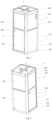
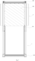
FIG. 1 is a structural schematic diagram illustrating an office soundproof compartment according to some embodiments of the present disclosure. -
FIG. 2 is a schematic diagram of another angle illustrating an office soundproof compartment according to some embodiments of the present disclosure. -
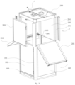
FIG. 3 is a structural schematic diagram illustrating a mounted state of an office soundproof compartment according to some embodiments of the present disclosure. -
FIG. 4 is a schematic diagram of another angle illustrating a mounted state of an office soundproof compartment according to some embodiments of the present disclosure. -
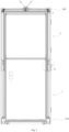
FIG. 5 is a sectional structural schematic diagram illustrating an office soundproof compartment according to some embodiments of the present disclosure. -
FIG. 6 is an enlarged structural schematic diagram of the part A inFIG. 5 . -
FIG. 7 is an enlarged structural schematic diagram of the part B inFIG. 5 . -
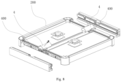
FIG. 8 is a schematic diagram illustrating an assembling structure of a top plate of an office soundproof compartment according to some embodiments of the present disclosure. -
FIG. 9 is a sectional structural schematic diagram illustrating a fixed side plate of an office soundproof compartment according to some embodiments of the present disclosure. -
FIG. 10 is a structural schematic diagram illustrating a first upper compartment plate of an office soundproof compartment according to some embodiments of the present disclosure. -
FIG. 11 is a sectional structural schematic diagram illustrating a movable lock plate of an office soundproof compartment according to some embodiments of the present disclosure. -
FIG. 12 is a structural schematic diagram illustrating an office soundproof compartment according to some other embodiments of the present disclosure. -
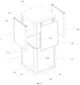
FIG. 13 is a schematic diagram illustrating the mounting of an upper compartment plate of an office soundproof compartment according to some other embodiments of the present disclosure. -
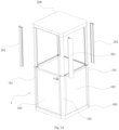
FIG. 14 is a schematic diagram illustrating the mounting of a support plate of an office soundproof compartment according to some other embodiments of the present disclosure. - Numerals of the drawings are described below:
1. lower compartment body, 100. seat, 101. telescoping column, 102. lower compartment plate, 103. slide groove, 104. sealing strip, 1010. outer tube, 1011. inner tube, 1012. gear box, 1013. second component, 1014. first component, 1015. driving nut, 2. upper compartment body, 200. top plate, 201. first upper compartment plate, 202. second upper compartment plate, 203. third upper compartment plate, 204. support plate, 205. fixed side plate, 206. fourth upper compartment plate, 3. compartment door, 300. handle, 4. drive motor, 400. transmission rod, 5. slide wheel, 6. support foot, 7. lock plate, 700. drive mouth, 701. base, 702. rack, 703. drive gear. - Firstly, those skilled in the arts should understand that these embodiments are used only to interpret the technical principle of the embodiments of the present disclosure rather than limit the scope of protection of the embodiments of the present disclosure. Those skilled in the arts can make adjustment thereto to adapt to the specific application scenarios.
- In the descriptions of the embodiments of the present disclosure, it should be noted that, unless otherwise clearly stated or defined, the terms "connect" and "couple", and the like shall be understood in a broad sense, for example, may be fixed connection, or detachable connection, or formed into one piece; or may be mechanical connection, or electrical connection; or direct connection or indirect connection through an intermediate medium. Those skilled in the art may understand the specific meanings of the above terms in the present disclosure according to actual situations.
- In the embodiments of the present disclosure, unless otherwise clearly stated or defined, the first feature being "on" or "below" the second feature refers to that the first feature and the second feature are in direct contact, or the first feature and the second feature are in indirect contact through an intermediate medium. Furthermore, the first feature being "above" or "on" the second feature refers to that the first feature is exactly above or obliquely above the second feature, or only refers to that the first feature has a higher horizontal height than the second feature. The first feature being "under" or "below" the second feature refers to that the first feature is exactly under or obliquely below the second feature, or only refers to that the first feature has a smaller horizontal height than the second feature.
- The present disclosure will be further detailed below in combination with drawings and specific embodiments.
- As shown in
FIGS. 1 to 11 , an embodiment of the present disclosure provides an office soundproof compartment, which structurally comprises alower compartment body 1 and anupper compartment body 2. Thelower compartment body 1 comprises aseat 100 and a plurality oflower compartment plates 102. Four vertically-disposedtelescoping columns 101 are connected at four corners of theseat 100. Thelower compartment plates 102 are connected between twoadjacent telescoping columns 101. In this embodiment, there are fourlower compartment plates 102, and theseat 100, the fourlower compartment plates 102 and the fourtelescoping columns 101 are jointly enclosed to form thelower compartment body 1 with bottom and surrounding closed and top opened. - The
telescoping columns 101 in this embodiment may be electrically-lifted telescoping columns or manually-lifted telescoping columns. The basic structure of thetelescoping columns 101 comprises an outer tube and an inner tube, where the inner tube is slidably cooperated in an inner hole of the outer tube and can extend or retract axially relative to the outer tube. It can be easily understood that when the inner tube slidably extends or retracts relative to the outer tube, the telescoping can be driven manually or by another lifting mechanism which at least comprises a lifter and a hydraulic jack and the like. Specifically, the another lifting mechanism may be disposed inside the telescoping columns; or, the another lifting mechanism may be disposed outside the telescoping columns, for example, disposed in the upper compartment body or the lower compartment body, and when the lifting action is completed, the another lifting mechanism may be moved out. This use can be repeated to reduce the costs. - As shown in
FIGS. 1, 2 ,3 , and4 , in this embodiment, theupper compartment body 2 of the office soundproof compartment comprisestop plates 200 and a fixedside plate 205. Thetop plates 200 are connected with thetelescoping columns 101 such that thetop plates 200 can move up and down along with thetelescoping columns 101 and thus thetop plates 200 are in an extended or retracted state relative to thelower compartment body 1. The fixedside plate 205 is vertically disposed and connected to thetop plate 200 and can extend or retract along with thetop plate 200. Theupper compartment body 2 further comprises a plurality of upper compartment plates, one end of which is connected to thelower compartment body 1 and the other end is detachably connected with thetop plates 200 when thetop plates 200 are in extended state. Thetop plates 200, the fixedside plate 205, thetelescoping columns 101 and the upper compartment plates are enclosed to form theupper compartment body 2 with bottom opened and surrounding closed. - In this embodiment, the office soundproof compartment further comprises a
compartment door 3 which is disposed on a sidewall of a same side of theupper compartment body 2 and thelower compartment body 1 for people to enter the compartment body. In order to help open thecompartment door 3, ahandle 300 is disposed on thecompartment door 3 and one side of thecompartment door 3 is rotatably connected to thetelescoping column 101 to enable thecompartment door 3 to be rotatably opened or closed. Specifically, onelower compartment plate 102 of thelower compartment body 1 is movably connected to onetelescoping column 101 to form a lower half part of thecompartment door 3, and an upper compartment plate horizontally opposed to the fixedside plate 205 in theupper compartment body 2 is movably connected to onetelescoping column 101 to form an upper half part of thecompartment door 3. It can be easily understood that the bottom of the upper half part of thecompartment door 3 is connected to the top of the lower half part of thecompartment door 3 to enable thecompartment door 3 to be entirely rotatably opened or closed. - In this embodiment, the upper compartment plate of the upper half part of the
compartment door 3 and thelower compartment plate 102 of the lower half part of thecompartment door 3 are both disposed as transparent such that there will be better light inside the office soundproof compartment. - By referring to
FIGS. 3 and4 again, when the office soundproof compartment is mounted by a user after purchase, thetelescoping columns 101 are firstly extended by using the lifting mechanism and at this time, thetelescoping columns 101 can enable thetop plates 200 of theupper compartment body 2 to synchronously extend together with the fixedside plate 205. The fixedside plate 205 extends out to serve as a partial sidewall of theupper compartment body 2, namely, there is no need to mount one upper compartment plate on a sidewall of theupper compartment body 2 where the fixedside plate 205 is located. Moreover, after thetop plates 200 and the fixedside plate 205 extend out, the basic frame of theupper compartment body 2 is formed, and then the upper compartment plates are mounted in sequence. In this way, the number of the upper compartment plates is reduced and the mounting procedure of thetop plates 200 is saved, and thus, the office soundproof compartment can be quickly and easily mounted. Similarly, during factory-leaving packaging and transportation of the office soundproof compartment, the upper compartment plates may be firstly dismounted and thetelescoping columns 101 are retracted while thetop plates 200 and the fixedside plate 205 are also retracted; hence, thetop plates 200 are moved close to thelower compartment body 1 so as to reduce the volume, save the packaging costs, occupy less transportation space, and help the handling. - With reference to
FIGS. 5 to 8 , in this embodiment, thetelescoping columns 101 comprise anouter tube 1010 and aninner tube 1011. Theinner tube 1011 is slidably cooperated in an inner hole of theouter tube 1010 and can extend or retract axially relative to the outer tube. Theouter tube 1010 is connected to theseat 100 to form a fixing part of thetelescoping columns 101. A length of theouter tube 1010 matches a height of thelower compartment body 1. Theinner tube 1011 forms a movable part of thetelescoping columns 101 with its extending height matching a height of theupper compartment body 2. In this embodiment, theouter tube 1010 and theinner tube 1011 each are integrally formed with profile material and can be axially slid but circumferentially rotatably limited. - In this embodiment, the office soundproof compartment further comprises a lifting mechanism. The lifting mechanism comprises a
first component 1014 and asecond component 1013 movable relative to thefirst component 1014. Thefirst component 1014 is connected to thelower compartment body 1 and thesecond component 1013 is connected to thetop plate 200 to enable thetop plate 200 to move up and down along with thesecond component 1013 and thus thetop plate 200 is maintained in extended or retracted state relative to thelower compartment body 1. The lifting mechanism is disposed inside thetelescoping columns 101. Furthermore, the lifting mechanism may further comprise agear box 1012 mounted at the top end of theinner tube 1011. A power input end of thegear box 1012 is in transmission connection with a drive mechanism and a power output end of thegear box 1012 is connected to the vertically-disposedsecond component 1013. The vertically-disposedfirst component 1014 is connected in the inner hole of theouter tube 1010. Thesecond component 1013 is in clearance fit with thefirst component 1014. Further, a drivingnut 1015 thread-connected with thesecond component 1013 is connected on an inner wall of thefirst component 1014. When thesecond component 1013 rotates, theinner tube 1011 can extend or retract relative to theouter tube 1010. - With reference to
FIGS. 5 to 8 , in some embodiments, the office soundproof compartment may further comprise a drive mechanism which is connected to thetop plate 200 and is in transmission connection with the lifting mechanism so as to drive the lifting mechanism to move up and down. The drive mechanism is adrive motor 4. When the office soundproof compartment is mounted, thedrive motor 4 may be started such that thedrive motor 4 drives the lifting mechanism to bring thetelescoping column 101 to automatically move up and down, resulting in simple and convenient operations. Specifically, in this embodiment, there are fourtelescoping columns 101 which are respectively connected to four corners of theseat 100, and the fourtelescoping columns 101 are respectively connected to thetop plates 200. In this embodiment, there are also four lifting mechanisms which are disposed inside fourtelescoping columns 101 respectively. In this embodiment, the drive mechanism comprises twodrive motors 4, each of which is in transmission connection with two lifting mechanisms, namely, twodrive motors 4 are mounted at both sides of the top of thetop plates 200 such that onedrive motor 4 drives two lifting mechanisms to move up and down by atransmission rod 400. - In other embodiments, the drive mechanism may also comprise one
drive motor 4 which drives four lifting mechanisms and hence moves the fourtelescoping columns 101 up and down by a transmission component; or, the drive mechanism may also comprise fourdrive motors 4 which are respectively connected inside fourtelescoping columns 101 and in transmission connection with the lifting mechanisms in thetelescoping columns 101. - In other embodiments, there may be one or two or three lifting mechanisms which are disposed in some
telescoping columns 101 and driven to move up and down by one ormore drive motors 4; or the lifting mechanisms may also be disposed outside thetelescoping columns 101. - In other embodiments, the lifting mechanism may also be an electric push rod. In other words, a mutually-sleeved screw-nut assembly is disposed inside the telescoping columns. The outer tube may be fixedly connected with a screw and the inner tube is fixedly connected with a nut. Further, a built-in motor is disposed in the telescoping columns to drive the screw to spin and hence generate a relative position change between the screw and the nut, and therefore achieve relative position change between the inner tube and the outer tube. Moreover, a control button and a control box are disposed on a surface of the seat and/or the telescoping columns to achieve synchronous movement of the four telescoping columns by one button. In this way, the office soundproof compartment can be more easily and quickly assembled. Of course, the lifting mechanism may also be another common lifting structure such as gas spring or hydraulic push rod or the like.
- By referring to
FIGS. 3 and4 again, in some embodiments, the lower end of at least one upper compartment plate of theupper compartment body 2 is hinged to the top of thelower compartment body 1, and when thetop plate 200 is in extended state, the upper compartment plate is enabled to rotate upward to connect with the bottom of thetop plate 200. Furthermore, the lower ends of two upper compartment plates are hinged to both sides of the top of thelower compartment body 1 respectively and the two upper compartment plates are also disposed at both sides of the fixedside plate 205 respectively. In this embodiment, there are three upper compartment plates disposed: a firstupper compartment plate 201, a secondupper compartment plate 202 and a thirdupper compartment plate 203. The firstupper compartment plate 201 and the secondupper compartment plate 202 are respectively disposed at both sides of the fixedside plate 205 while the firstupper compartment plate 201 and the secondupper compartment plate 202 are opposed to each other. The bottoms of the firstupper compartment plate 201 and the secondupper compartment plate 202 are respectively hinged to the top of thelower compartment body 1 by hinging pins. When the office soundproof compartment leaves factory, the firstupper compartment plate 201 and the secondupper compartment plate 202 are pre-mounted, that is, the lower ends of the firstupper compartment plate 201 and the secondupper compartment plate 202 are connected to thelower compartment body 1 by hinging pins. When thetelescoping columns 101 extend out and theupper compartment body 2 is to be assembled, it is only required to rotate up the firstupper compartment plate 201 and the secondupper compartment plate 202 to enable the tops of the firstupper compartment plate 201 and the secondupper compartment plate 202 to be connected with the bottoms of thetop plates 200. It is not necessary to take time to determine the correct mounting positions of the firstupper compartment plate 201 and the secondupper compartment plate 202, thus saving time. Furthermore, after the firstupper compartment plate 201 and the secondupper compartment plate 202 are connected, there is only one side left un-mounted for the entireupper compartment body 2. At this time, the remaining thirdupper compartment plate 203 may be connected at this side. Therefore, the three upper compartment plates can be easily mounted without taking time to determine their mounting positions. - With reference to
FIGS. 10 and 11 , in some embodiments, at least onemovable lock plate 7 capable of extending out of or retracting into the upper compartment plates hinged to the top of thelower compartment body 1 is connected inside the upper compartment plates. When the upper compartment plate is rotated upward to connect with the bottom of thetop plate 200, thelock plate 7 may extend upward out of the upper compartment plate to fit with thetop plate 200 so as to fix the upper compartment plate. In this embodiment, themovable lock plate 7 comprises a base 701 mounted inside the upper compartment plate. Thelock plate 7 capable of extending out of or retracting into the upper compartment plate is cooperated slidably in thebase 701. Arack 702 is disposed on thelock plate 7, adrive gear 703 meshed with therack 702 is rotatably connected in thebase 701 and adrive mouth 700 rotating thedrive gear 703 is exposed out of the upper compartment plate. In this case, when thedrive mouth 700 of thedrive gear 703 is rotated by a tool, thedrive gear 703 can be rotated, so as to drive thelock plate 7 to move up and down, that is, extend out of or retract into the upper compartment plate. Thelock plate 7 may extend out of the upper compartment plate to fit with thetop plate 200 so as to enable the upper end of the upper compartment plate to connect thetop plate 200. - In other embodiments, the
movable lock plate 7 may also be an elastic buckle or elastic barb connected to the top of the upper compartment plates. Further, the upper ends of the upper compartment plates may be connected to thetop plates 200 by screws such that the upper compartment plates can be more simply and quickly connected to thetop plates 200. - By referring to
FIG. 3 again, in some embodiments, theupper compartment body 2 may further comprisesupport plates 204 in one-to-one correspondence with thetelescoping columns 101. When thetelescoping columns 101 are in extended state, thesupport plates 204 are wrapped on thetelescoping columns 101, with the upper ends of thesupport plates 204 abutted against the bottoms of thetop plates 200 and the lower ends of thesupport plates 204 abutted against the top of thelower compartment body 1. Thesupport plates 204 are used to compensate a thickness difference between the movable part and the fixing part of thetelescoping columns 101. Thesupport plates 204 can prevent thetop plates 200 from automatically sliding down and achieve supporting effect on thetop plates 200 and thetelescoping columns 101 in extended state. Furthermore, after the office soundproof compartment is mounted, the surface of the outer sidewall of theupper compartment body 2 and thelower compartment body 1 can be entirely flat due to the disposal of thesupport plates 204. Moreover, after thesupport plates 204 are mounted, a mounting space for mounting the upper compartment plates is formed between twoadjacent support plates 204. After the upper compartment plates are mounted, there is a small gap or no gap between the upper compartment plates and thesupport plates 204, so as to achieve good soundproofing effect for the office soundproof compartment. - Furthermore, in order to improve the soundproofing effect of the office soundproof compartment, a sealing gasket is used at the connection of the
lower compartment body 1 and theupper compartment body 2 and the connection of thelower compartment plates 102 and the upper compartment plates; in addition, a soundproof cotton may be disposed inside thelower compartment plates 102 and the upper compartment plates to improve the soundproofing effect. - By referring to
FIGS. 3 and9 , in some embodiments, twoslide grooves 103 with opposed openings are connected on two inner sidewalls of thelower compartment body 1 and disposed at a side of thelower compartment body 1 away from thecompartment door 3. Further, the fixedside plate 205 is cooperated slidably in the twoslide grooves 103. When thetelescoping columns 101 drive thetop plates 200 and the fixedside plate 205 to move up and down, the disposal of the twoslide grooves 103 can achieve guiding effect on the movement of the fixedside plate 205 and prevent the fixedside plate 205 from swinging during slide process. In this way, it is ensured that the fixedside plate 205 can move up and down stably. In this embodiment, the twoslide grooves 103 are integrally formed by theouter tubes 1010 of twotelescoping columns 101, that is, theslide grooves 103 are integrally formed on the profile material of theouter tubes 1010 of thetelescoping columns 101. Therefore, it is not required to mountindependent slide grooves 103, making its structure more compact. - Furthermore, in some embodiments, a
soft sealing strip 104 extending along a length direction of theslide grooves 103 and capable of being attached to the surface of the fixedside plate 205 is connected to an inner wall of theslide grooves 103. The soft sealing strips 104 are of a rubber material. The disposal of the soft sealing strips 104 can not only reduce the swing of the fixedside plate 205 during slide process but also achieve sealing effect on the edges of both sides of the fixedside plate 205, achieving good soundproofing effect of the office soundproof compartment. - By referring to
FIG. 4 again, in order to help to change the position of the office soundproof compartment,slide wheels 5 are connected at the bottom of theseat 100. Further, in order to help adjust the standing stability of the office soundproof compartment, a plurality of height-adjustable support feet 6 are connected at the bottom of theseat 100. Thesupport feet 6 are connected to the bottom of theseat 100 by screws, and can be adjusted in height by rotating thesupport feet 6. - By referring to
FIGS. 12 ,13 and14 , in some other embodiments, the structure of the office soundproof compartment may comprise alower compartment body 1 and anupper compartment body 2, where thelower compartment body 1 comprises aseat 100 and a plurality oflower compartment plates 102. Four vertically-disposedtelescoping columns 101 are connected at four corners of theseat 100, and thelower compartment plates 102 are connected between twoadjacent telescoping columns 101. In this embodiment, there are fourlower compartment plates 102, and theseat 100, the fourlower compartment plates 102 and the fourtelescoping columns 101 are jointly enclosed to form thelower compartment body 1 with bottom and surrounding closed and top opened. Furthermore, in this embodiment, there are four upper compartment plates: a firstupper compartment plate 201, a secondupper compartment plate 202, a thirdupper compartment plate 203 and a fourthupper compartment plate 206. The firstupper compartment plate 201 and the secondupper compartment plate 202 are disposed at both sides of theupper compartment body 2 respectively such that the firstupper compartment plate 201 is opposed to the secondupper compartment plate 202, and the bottoms of the firstupper compartment plate 201 and the secondupper compartment plate 202 are hinged to the top of thelower compartment body 1 by hinging pins respectively. The thirdupper compartment plate 203 and the fourthupper compartment plate 206 are respectively disposed at another two sides such that the thirdupper compartment plate 203 is opposed to the fourthupper compartment plate 206, where the thirdupper compartment plate 203 is an upper half part of thecompartment door 3. When the office soundproof compartment leaves factory, the firstupper compartment plate 201 and the secondupper compartment plate 202 are pre-mounted, namely, the lower ends of the firstupper compartment plate 201 and the secondupper compartment plate 202 are connected to thelower compartment body 1 by hinging pins. When thetelescoping columns 101 extend out and theupper compartment body 2 is to be assembled, it is only required to rotate up the firstupper compartment plate 201 and the secondupper compartment plate 202 to enable the tops of the firstupper compartment plate 201 and the secondupper compartment plate 202 to be connected with the bottoms of thetop plates 200. It is not necessary to take time to determine the correct mounting positions of the firstupper compartment plate 201 and the secondupper compartment plate 202, thus saving time. Furthermore, after the firstupper compartment plate 201 and the secondupper compartment plate 202 are connected, there are only two sides left un-mounted for the entireupper compartment body 2. At this time, the thirdupper compartment plate 203 and the fourthupper compartment plate 206 can be connected at the two sides. Therefore, the four upper compartment plates can be easily mounted for theupper compartment body 2 without taking time to determine their mounting positions. - Another embodiment of the present disclosure provides a mounting method of an office soundproof compartment. The office soundproof compartment comprises a
lower compartment body 1 and anupper compartment body 2, where thelower compartment body 1 comprises aseat 100 and four telescoping columns connected at four corners of theseat 100. Alower compartment plate 102 is connected between twoadjacent telescoping columns 101. Thelower compartment plates 102, thetelescoping columns 101 and theseat 100 are enclosed to form thelower compartment body 1 with top opened and surrounding closed. Theupper compartment body 2 comprises atop plate 200 and a fixedside plate 205. The top plates are connected to the fourtelescoping columns 101 to enable thetop plates 200 to synchronously move up and down along with thetelescoping columns 101, and thus thetop plates 200 are maintained in an extended or retracted state relative to thelower compartment body 1. The fixedside plate 205 is vertically disposed and connected to thetop plate 200 and can extend or retract in synchronization with thetop plate 200. Theupper compartment body 2 further comprises three upper compartment plates: a firstupper compartment plate 201, a secondupper compartment plate 202 and a thirdupper compartment plate 203. The firstupper compartment plate 201 and the secondupper compartment plate 202 are disposed at both sides of the fixedside plate 205, with their lower ends hinged to thelower compartment body 1 respectively. Theupper compartment body 2 further comprises foursupport plates 204 in one-to-one correspondence with the fourtelescoping columns 101. The office soundproof compartment further comprises a lifting mechanism and a drive mechanism. The lifting mechanism is disposed inside eachtelescoping column 101 and comprises afirst component 1014 and asecond component 1013 movable relative to thefirst component 1014. Thefirst component 1014 is connected to thelower compartment body 1 and thesecond component 1013 is connected to thetop plate 200 to enable thetop plate 200 to move up and down along with thesecond component 1013. Thus, thetop plate 200 is maintained in extended or retracted state relative to thelower compartment body 1. The drive mechanism is connected to thetop plates 200 and is in respective transmission connection with the lifting mechanisms to drive the lifting mechanisms and hence move thetelescoping columns 104 up and down. - The office soundproof compartment in this embodiment may be mounted after purchase by the following method: S1: the
drive motor 4 is started to drive the lifting mechanisms to extend out fourtelescoping columns 101 and hence thetop plates 200 and the fixedside plate 205 are in extended state relative to thelower compartment body 1; S2: the foursupport plates 204 are respectively connected to the fourtelescoping columns 101 with the upper ends of thesupport plates 204 abutted against the bottoms of thetop plates 200 and the lower ends of thesupport plates 204 abutted against the top of thelower compartment body 1; S3: the firstupper compartment plate 201 and the secondupper compartment plate 202 are rotated upward to enable the upper ends of the firstupper compartment plate 201 and the secondupper compartment plate 202 to be connected with the bottoms of thetop plates 200 respectively; S4: the thirdupper compartment plate 203 is mounted to enable thetop plates 200, the fixedside plate 205, the three upper compartment plates and the fourtelescoping columns 101 to be enclosed to form theupper compartment body 2 with lower end opened and surrounding closed. - In the mounting method of the office soundproof compartment, after the office soundproof compartment is purchased by a user, the office soundproof compartment can be assembled by the following method without aligning each component: the drive mechanism is firstly started to extend out the
telescoping columns 101, while thetop plates 200 and the fixedside plate 205 are extended out; at this time, the basic frame of theupper compartment body 2 is formed, and the fixedside plate 205 can serve as one sidewall of theupper compartment body 2; then, foursupport plates 204 are respectively wrapped on the fourtelescoping columns 101, and the foursupport plates 204 compensate a thickness difference between the movable part and the fixing part of thetelescoping columns 101, and further, a mounting space for mounting the upper compartment plates is formed betweenadjacent telescoping columns 101; the user then rotates up the firstupper compartment plate 201 and the secondupper compartment plate 202 to enable the tops of the firstupper compartment plate 201 and the secondupper compartment plate 202 to be connected with the bottoms of thetop plates 200; finally, the thirdupper compartment plate 203 is mounted. Since the firstupper compartment plate 201 and the secondupper compartment plate 202 are pre-hinged to thelower compartment body 1, that is, since their mounting positions are already determined, it is not required to take time to determine the correct mounting positions of the firstupper compartment plate 201 and the secondupper compartment plate 202, saving time. After the firstupper compartment plate 201 and the secondupper compartment plate 202 are respectively connected, there is only one side left un-mounted for the entireupper compartment body 2. At this time, the remaining thirdupper compartment plate 203 is connected at this side. Therefore, the three upper compartment plates can be quickly and easily mounted without taking time to determine their mounting positions. The mounting method of the office soundproof compartment helps the user to perform the mounting process more simply, more conveniently and move quickly after purchase, bringing good experiences to the users. - In the descriptions of the embodiments of the present disclosure, it is noted that, in the descriptions of the present disclosure, the terms "inner", "outer" and the like indicating direction or positional relationship are based on the direction or positional relationship shown in drawings and are used for the purpose of ease of descriptions rather than indicating or implying the device or member must have a specific orientation or be constructed or operated in a specific orientation and thus these terms shall not be understood as limiting of the present disclosure.
- In the descriptions of the present disclosure, the descriptions by referring to the terms "one embodiment", "some embodiments" "in this embodiment", "specific example" or "some examples" or the like mean that the specific features, mechanisms, materials or characteristics described in combination with this embodiment or example are incorporated in at least one embodiment or example of the present disclosure. In this specification, the illustrative expressions of the above terms are not necessarily directed to same embodiment or example. Furthermore, the described specific features, mechanisms, materials or characteristics may be combined in an appropriate way in one or more embodiments or examples. Moreover, in a case of no conflicts, those skilled in the arts may perform combination for different embodiments or examples and the features of different embodiments or examples in the specification.
- The above descriptions are only the specific embodiments of the present disclosure but the scope of protection of the present disclosure is not limited hereto. All changes or substitutions those skilled in the arts can easily conceive of within the technical scope of the present disclosure shall fall within the scope of protection of the present disclosure. Therefore, the scope of protection of the present disclosure shall be indicated by the claims.
Claims (15)
- An office soundproof compartment, wherein the compartment comprisesa lower compartment body (1), comprising a seat (100), telescoping columns (101) and a plurality of lower compartment plates (102);the seat, the telescoping columns and the plurality of lower compartment plates are enclosed to form the lower compartment body with top opened and surrounding closed;an upper compartment body (2), comprising top plates (200) and a plurality of upper compartment plates (201, 202, 203) the top plates are connected to the telescoping columns and can move in synchronization with the telescoping columns and the top plates are maintained in extended or retracted state relative to the lower compartment body; one end of at least one of the upper compartment plates is connected to the lower compartment body, and the other end is detachably connected with the top plate when the top plate is in extended state; when the top plates are in extended state, the top plates, the telescoping columns and all the upper compartment plates are enclosed to form the upper compartment body with lower end opened and surrounding closed; the bottom of the upper compartment body is connected to the top of the lower compartment body; and after the upper compartment plates are separated from the upper compartment body, the top plates can move to the retracted state along with the telescoping columns;a compartment door (3), disposed on a sidewall of a same side of the upper compartment body and the lower compartment body for people to enter the compartment body.
- The office soundproof compartment of claim 1, wherein the upper compartment body further comprises a fixed side plate; the fixed side plate is vertically disposed and connected to the top plate and is capable of extending out or retracting along with the top plate; when the top plates are in extended state, the top plates, the fixed side plate, the telescoping columns and all the upper compartment plates are enclosed to form the upper compartment body with lower end opened and surrounding closed;; and after the upper compartment plates are separated from the upper compartment body, the top plates and the fixed side plate move to the retracted state along with the telescoping columns.
- The office soundproof compartment of claim 1 or claim 2, wherein the office soundproof compartment further comprises a lifting mechanism; the lifting mechanism comprises a first component and a second component movable relative to the first component; the first component is connected to the lower compartment body and the second component is connected to the top plate to enable the top plate to move up and down along with the second component and thus the top plate is maintained in extended or retracted state relative to the lower compartment body; the lifting mechanism is disposed inside the telescoping columns, and/or the lifting mechanism can be movably disposed inside the upper compartment body and the lower compartment body.
- The office soundproof compartment of claim 3, wherein the office soundproof compartment further comprises a drive mechanism which is connected to the top plate and is in transmission connection with the lifting mechanism to drive the lifting mechanism to move up and down.
- The office soundproof compartment of claim 4, wherein there are a plurality of lifting mechanisms which are respectively disposed inside corresponding telescoping columns; the first component is connected to the outer tube of the telescoping column and the second component is connected to the inner tube of the telescoping column to drive the inner tube of the telescoping column to move relative to the outer tube and make the telescoping column extend or retract.
- The office soundproof compartment of claim 4 or claim 5, wherein there are four lifting mechanisms and four telescoping columns; the four telescoping columns are respectively connected to four corners of the lower compartment body, and respectively connected to the top plates; the drive mechanism comprises two drive motors, each of which is in transmission connection with two lifting mechanisms respectively; or the drive mechanism comprises one drive motor which is in transmission connection with the four lifting mechanisms respectively.
- The office soundproof compartment of claim 1 or claim 2, wherein the lower end of at least one upper compartment plate of the upper compartment body is hinged to the top of the lower compartment body, and when the top plate is in extended state, the upper compartment plate is enabled to rotate upward to connect with the bottom of the top plate.
- The office soundproof compartment of claim 7, wherein the lower ends of two upper compartment plates are hinged respectively to both sides of the top of the lower compartment body, and the two upper compartment plates are disposed at two opposed sides of the upper compartment body.
- The office soundproof compartment of claim 8, wherein at least one movable lock plate capable of extending out of or retracting into the upper compartment plates hinged to the top of the lower compartment body is connected inside the upper compartment plates; when the upper compartment plate is rotated upward to connect with the bottom of the top plate, the lock plate may extend upward out of the upper compartment plate to fit with the top plate to fix the upper compartment plate.
- The office soundproof compartment of claim 6, wherein the upper compartment body further comprises support plates in one-to-one correspondence with the telescoping columns; when the telescoping columns are in extended state, the support plates are correspondingly wrapped on the telescoping columns, with the upper ends of the support plates abutted against the bottoms of the top plates and the lower ends of the support plates abutted against the top of the lower compartment body; the support plates are used to compensate a thickness difference between the movable part and the fixing part of the telescoping columns and support the top plates.
- The office soundproof compartment of claim 1, wherein one lower compartment plate of the lower compartment body is movably connected to one telescoping column to form a lower half part of the compartment door, and a handle is disposed on the compartment door; one upper compartment plate vertically opposed to the lower half part of the compartment door in the upper compartment body is movably connected to one telescoping column to form an upper half part of the compartment door; the upper compartment plate and the lower compartment plate of the compartment door are both disposed as transparent.
- The office soundproof compartment of claim 2, wherein two slide grooves with opposed openings are connected on two inner sidewalls of the lower compartment body and disposed at a side of the lower compartment body away from the compartment door; the fixed side plate is cooperated slidably in the two slide grooves.
- The office soundproof compartment of claim 12, wherein a soft sealing strip extending along a length direction of the slide grooves and capable of being attached to the surface of the fixed side plate is connected to an inner wall of the slide grooves.
- The office soundproof compartment of claim 7, wherein the lower ends of two upper compartment plates are hinged to both sides of the top of the lower compartment body respectively and the two upper compartment plates are disposed at both sides of the fixed side plate respectively.
- A mounting method of an office soundproof compartment, wherein
the office soundproof compartment comprises:a lower compartment body (1), comprising a seat (100) and four telescoping columns (101) connected to four corners of the seat; a lower compartment plate is connected between two adjacent telescoping columns, and the lower compartment plates, the telescoping columns and the seat are enclosed to form the lower compartment body with top opened and surrounding closed;an upper compartment body (2), comprising top plates (200) and a fixed side plate (205); the top plates are connected to the four telescoping columns to enable the top plates to move up and down along with the telescoping columns and thus the top plates are maintained in extended or retracted state relative to the lower compartment body; the fixed side plate is vertically disposed and connected to the top plate and is capable of extending out or retracting along with the top plates; the upper compartment body further comprises three upper compartment plates (201, 202, 203):a first upper compartment plate, a second upper compartment plate and a third upper compartment plate, and the first upper compartment plate and the second upper compartment plate are disposed at both sides of the fixed side plate, with their lower ends hinged to the lower compartment body; the upper compartment body further comprises four support plates in one-to-one correspondence with the four telescoping columns;a lifting mechanism, comprising a first component and a second component movable relative to the first component; the first component is connected to the lower compartment body and the second component is connected to the top plate to enable the top plate to move up and down along with the second component, and the top plate is maintained in extended or retracted state relative to the lower compartment body;a drive mechanism, connected to the top plates and being in transmission connection with the lifting mechanisms to drive the lifting mechanisms;the mounting method comprises the following steps:S1: the drive mechanism is started to drive four telescoping columns to extend out and hence the top plates and the fixed side plate are in extended state relative to the lower compartment body 1;S2: the four support plates are respectively connected to the four telescoping columns with the upper ends of the support plates abutted against the bottoms of the top plates and the lower ends of the support plates abutted against the top of the lower compartment body;S3: the first upper compartment plate and the second upper compartment plate are rotated upward to enable the upper ends of the first upper compartment plate and the second upper compartment plate to be connected with the bottoms of the top plates respectively;S4: the third upper compartment plate is mounted such that the top plates, the fixed side plate, the three upper compartment plates and the four telescoping columns to are enclosed to form the upper compartment body with lower end opened and surrounding closed.
Applications Claiming Priority (2)
| Application Number | Priority Date | Filing Date | Title |
|---|---|---|---|
| CN202211739252.7A CN116122632A (en) | 2022-12-31 | 2022-12-31 | Office sound insulation cabin |
| CN202310615659.7A CN116591521A (en) | 2023-05-26 | 2023-05-26 | An office soundproof warehouse and its installation method |
Publications (2)
| Publication Number | Publication Date |
|---|---|
| EP4394141A1 EP4394141A1 (en) | 2024-07-03 |
| EP4394141B1 true EP4394141B1 (en) | 2025-03-26 |
Family
ID=88874499
Family Applications (1)
| Application Number | Title | Priority Date | Filing Date |
|---|---|---|---|
| EP23210782.1A Active EP4394141B1 (en) | 2022-12-31 | 2023-11-18 | Office soundproof compartment and mounting method thereof |
Country Status (2)
| Country | Link |
|---|---|
| US (1) | US20240218653A1 (en) |
| EP (1) | EP4394141B1 (en) |
Family Cites Families (3)
| Publication number | Priority date | Publication date | Assignee | Title |
|---|---|---|---|---|
| CN204225521U (en) * | 2014-09-18 | 2015-03-25 | 金朝阳 | Between a kind of multifunctional sanitary |
| CN111601937B (en) * | 2017-12-14 | 2022-08-30 | Mad投资有限公司 | Transportable sanitary unit |
| CN213509738U (en) * | 2020-06-16 | 2021-06-22 | 重庆市疾病预防控制中心(重庆市救灾防病应急处理中心) | Telescopic room that gives sound insulation |
-
2023
- 2023-11-18 EP EP23210782.1A patent/EP4394141B1/en active Active
- 2023-12-06 US US18/531,114 patent/US20240218653A1/en active Pending
Also Published As
| Publication number | Publication date |
|---|---|
| US20240218653A1 (en) | 2024-07-04 |
| EP4394141A1 (en) | 2024-07-03 |
Similar Documents
| Publication | Publication Date | Title |
|---|---|---|
| CN113638499A (en) | A retractable folding house | |
| CN211622744U (en) | Folding private warehouse | |
| CN116122632A (en) | Office sound insulation cabin | |
| CN110700637A (en) | Folding private warehouse | |
| EP4394141A1 (en) | Office soundproof compartment and mounting method thereof | |
| JPH0747023A (en) | Mobile wall-mounted bed | |
| CN117211561A (en) | A lifting office soundproof warehouse | |
| CN114680524A (en) | Island cabinet and assembly process thereof | |
| CN110640701A (en) | Squirrel-cage sofa turnover device and sofa assembly machine | |
| CN222066294U (en) | Mute cabin | |
| CN112687179A (en) | Adjustable sand table for architectural design and display method thereof | |
| CN211114245U (en) | Mobile wall is built in room | |
| CN116591521A (en) | An office soundproof warehouse and its installation method | |
| CN221893758U (en) | Expansion type container | |
| CN221974739U (en) | Foot rest for man-machine interaction equipment | |
| CN222308812U (en) | Electronic component assembly table | |
| CN215889495U (en) | Movable folding stage | |
| CN220030182U (en) | Cabinet mouth frame cutting workbench | |
| CN118187528A (en) | A silent cabin | |
| CN221119127U (en) | Device for quickly adjusting height of tray-buckled scaffold base | |
| CN222592949U (en) | Processing equipment part recovery unit | |
| CN221997475U (en) | A teaching inflatable model display device | |
| CN219912515U (en) | Light cage type hanging bracket | |
| CN118486980B (en) | A modular outdoor energy storage cabinet | |
| CN216794432U (en) | Power reactive compensation cabinet for petrochemical industry |
Legal Events
| Date | Code | Title | Description |
|---|---|---|---|
| PUAI | Public reference made under article 153(3) epc to a published international application that has entered the european phase |
Free format text: ORIGINAL CODE: 0009012 |
|
| STAA | Information on the status of an ep patent application or granted ep patent |
Free format text: STATUS: REQUEST FOR EXAMINATION WAS MADE |
|
| 17P | Request for examination filed |
Effective date: 20231215 |
|
| AK | Designated contracting states |
Kind code of ref document: A1 Designated state(s): AL AT BE BG CH CY CZ DE DK EE ES FI FR GB GR HR HU IE IS IT LI LT LU LV MC ME MK MT NL NO PL PT RO RS SE SI SK SM TR |
|
| GRAP | Despatch of communication of intention to grant a patent |
Free format text: ORIGINAL CODE: EPIDOSNIGR1 |
|
| STAA | Information on the status of an ep patent application or granted ep patent |
Free format text: STATUS: GRANT OF PATENT IS INTENDED |
|
| INTG | Intention to grant announced |
Effective date: 20241014 |
|
| RIC1 | Information provided on ipc code assigned before grant |
Ipc: E04H 1/12 20060101ALN20241004BHEP Ipc: E04B 1/82 20060101AFI20241004BHEP |
|
| GRAS | Grant fee paid |
Free format text: ORIGINAL CODE: EPIDOSNIGR3 |
|
| GRAA | (expected) grant |
Free format text: ORIGINAL CODE: 0009210 |
|
| STAA | Information on the status of an ep patent application or granted ep patent |
Free format text: STATUS: THE PATENT HAS BEEN GRANTED |
|
| AK | Designated contracting states |
Kind code of ref document: B1 Designated state(s): AL AT BE BG CH CY CZ DE DK EE ES FI FR GB GR HR HU IE IS IT LI LT LU LV MC ME MK MT NL NO PL PT RO RS SE SI SK SM TR |
|
| REG | Reference to a national code |
Ref country code: GB Ref legal event code: FG4D |
|
| REG | Reference to a national code |
Ref country code: CH Ref legal event code: EP |
|
| REG | Reference to a national code |
Ref country code: DE Ref legal event code: R096 Ref document number: 602023002605 Country of ref document: DE |
|
| REG | Reference to a national code |
Ref country code: IE Ref legal event code: FG4D |
|
| PG25 | Lapsed in a contracting state [announced via postgrant information from national office to epo] |
Ref country code: RS Free format text: LAPSE BECAUSE OF FAILURE TO SUBMIT A TRANSLATION OF THE DESCRIPTION OR TO PAY THE FEE WITHIN THE PRESCRIBED TIME-LIMIT Effective date: 20250626 |
|
| PG25 | Lapsed in a contracting state [announced via postgrant information from national office to epo] |
Ref country code: FI Free format text: LAPSE BECAUSE OF FAILURE TO SUBMIT A TRANSLATION OF THE DESCRIPTION OR TO PAY THE FEE WITHIN THE PRESCRIBED TIME-LIMIT Effective date: 20250326 |
|
| REG | Reference to a national code |
Ref country code: LT Ref legal event code: MG9D |
|
| PG25 | Lapsed in a contracting state [announced via postgrant information from national office to epo] |
Ref country code: NO Free format text: LAPSE BECAUSE OF FAILURE TO SUBMIT A TRANSLATION OF THE DESCRIPTION OR TO PAY THE FEE WITHIN THE PRESCRIBED TIME-LIMIT Effective date: 20250626 |
|
| PG25 | Lapsed in a contracting state [announced via postgrant information from national office to epo] |
Ref country code: HR Free format text: LAPSE BECAUSE OF FAILURE TO SUBMIT A TRANSLATION OF THE DESCRIPTION OR TO PAY THE FEE WITHIN THE PRESCRIBED TIME-LIMIT Effective date: 20250326 |
|
| PG25 | Lapsed in a contracting state [announced via postgrant information from national office to epo] |
Ref country code: LV Free format text: LAPSE BECAUSE OF FAILURE TO SUBMIT A TRANSLATION OF THE DESCRIPTION OR TO PAY THE FEE WITHIN THE PRESCRIBED TIME-LIMIT Effective date: 20250326 |
|
| PG25 | Lapsed in a contracting state [announced via postgrant information from national office to epo] |
Ref country code: GR Free format text: LAPSE BECAUSE OF FAILURE TO SUBMIT A TRANSLATION OF THE DESCRIPTION OR TO PAY THE FEE WITHIN THE PRESCRIBED TIME-LIMIT Effective date: 20250627 Ref country code: BG Free format text: LAPSE BECAUSE OF FAILURE TO SUBMIT A TRANSLATION OF THE DESCRIPTION OR TO PAY THE FEE WITHIN THE PRESCRIBED TIME-LIMIT Effective date: 20250326 |
|
| REG | Reference to a national code |
Ref country code: NL Ref legal event code: MP Effective date: 20250326 |
|
| PG25 | Lapsed in a contracting state [announced via postgrant information from national office to epo] |
Ref country code: NL Free format text: LAPSE BECAUSE OF FAILURE TO SUBMIT A TRANSLATION OF THE DESCRIPTION OR TO PAY THE FEE WITHIN THE PRESCRIBED TIME-LIMIT Effective date: 20250326 |
|
| PG25 | Lapsed in a contracting state [announced via postgrant information from national office to epo] |
Ref country code: SE Free format text: LAPSE BECAUSE OF FAILURE TO SUBMIT A TRANSLATION OF THE DESCRIPTION OR TO PAY THE FEE WITHIN THE PRESCRIBED TIME-LIMIT Effective date: 20250326 |
|
| REG | Reference to a national code |
Ref country code: AT Ref legal event code: MK05 Ref document number: 1779106 Country of ref document: AT Kind code of ref document: T Effective date: 20250326 |
|
| PG25 | Lapsed in a contracting state [announced via postgrant information from national office to epo] |
Ref country code: SM Free format text: LAPSE BECAUSE OF FAILURE TO SUBMIT A TRANSLATION OF THE DESCRIPTION OR TO PAY THE FEE WITHIN THE PRESCRIBED TIME-LIMIT Effective date: 20250326 |
|
| PG25 | Lapsed in a contracting state [announced via postgrant information from national office to epo] |
Ref country code: ES Free format text: LAPSE BECAUSE OF FAILURE TO SUBMIT A TRANSLATION OF THE DESCRIPTION OR TO PAY THE FEE WITHIN THE PRESCRIBED TIME-LIMIT Effective date: 20250326 Ref country code: PT Free format text: LAPSE BECAUSE OF FAILURE TO SUBMIT A TRANSLATION OF THE DESCRIPTION OR TO PAY THE FEE WITHIN THE PRESCRIBED TIME-LIMIT Effective date: 20250728 |
|
| PG25 | Lapsed in a contracting state [announced via postgrant information from national office to epo] |
Ref country code: PL Free format text: LAPSE BECAUSE OF FAILURE TO SUBMIT A TRANSLATION OF THE DESCRIPTION OR TO PAY THE FEE WITHIN THE PRESCRIBED TIME-LIMIT Effective date: 20250326 Ref country code: IT Free format text: LAPSE BECAUSE OF FAILURE TO SUBMIT A TRANSLATION OF THE DESCRIPTION OR TO PAY THE FEE WITHIN THE PRESCRIBED TIME-LIMIT Effective date: 20250326 |
|
| PG25 | Lapsed in a contracting state [announced via postgrant information from national office to epo] |
Ref country code: AT Free format text: LAPSE BECAUSE OF FAILURE TO SUBMIT A TRANSLATION OF THE DESCRIPTION OR TO PAY THE FEE WITHIN THE PRESCRIBED TIME-LIMIT Effective date: 20250326 |
|
| PG25 | Lapsed in a contracting state [announced via postgrant information from national office to epo] |
Ref country code: EE Free format text: LAPSE BECAUSE OF FAILURE TO SUBMIT A TRANSLATION OF THE DESCRIPTION OR TO PAY THE FEE WITHIN THE PRESCRIBED TIME-LIMIT Effective date: 20250326 |
|
| PG25 | Lapsed in a contracting state [announced via postgrant information from national office to epo] |
Ref country code: RO Free format text: LAPSE BECAUSE OF FAILURE TO SUBMIT A TRANSLATION OF THE DESCRIPTION OR TO PAY THE FEE WITHIN THE PRESCRIBED TIME-LIMIT Effective date: 20250326 |
|
| PG25 | Lapsed in a contracting state [announced via postgrant information from national office to epo] |
Ref country code: SK Free format text: LAPSE BECAUSE OF FAILURE TO SUBMIT A TRANSLATION OF THE DESCRIPTION OR TO PAY THE FEE WITHIN THE PRESCRIBED TIME-LIMIT Effective date: 20250326 |
|
| PG25 | Lapsed in a contracting state [announced via postgrant information from national office to epo] |
Ref country code: IS Free format text: LAPSE BECAUSE OF FAILURE TO SUBMIT A TRANSLATION OF THE DESCRIPTION OR TO PAY THE FEE WITHIN THE PRESCRIBED TIME-LIMIT Effective date: 20250726 |
|
| PGFP | Annual fee paid to national office [announced via postgrant information from national office to epo] |
Ref country code: LU Payment date: 20251028 Year of fee payment: 3 |
|
| REG | Reference to a national code |
Ref country code: DE Ref legal event code: R097 Ref document number: 602023002605 Country of ref document: DE |
|
| PGFP | Annual fee paid to national office [announced via postgrant information from national office to epo] |
Ref country code: DE Payment date: 20251117 Year of fee payment: 3 |
|
| PGFP | Annual fee paid to national office [announced via postgrant information from national office to epo] |
Ref country code: MC Payment date: 20251027 Year of fee payment: 3 |
|
| PG25 | Lapsed in a contracting state [announced via postgrant information from national office to epo] |
Ref country code: DK Free format text: LAPSE BECAUSE OF FAILURE TO SUBMIT A TRANSLATION OF THE DESCRIPTION OR TO PAY THE FEE WITHIN THE PRESCRIBED TIME-LIMIT Effective date: 20250326 |
|
| PGFP | Annual fee paid to national office [announced via postgrant information from national office to epo] |
Ref country code: FR Payment date: 20251127 Year of fee payment: 3 |
|
| PGFP | Annual fee paid to national office [announced via postgrant information from national office to epo] |
Ref country code: BE Payment date: 20251120 Year of fee payment: 3 |
|
| PG25 | Lapsed in a contracting state [announced via postgrant information from national office to epo] |
Ref country code: CZ Free format text: LAPSE BECAUSE OF FAILURE TO SUBMIT A TRANSLATION OF THE DESCRIPTION OR TO PAY THE FEE WITHIN THE PRESCRIBED TIME-LIMIT Effective date: 20250326 |
|
| PGFP | Annual fee paid to national office [announced via postgrant information from national office to epo] |
Ref country code: IE Payment date: 20251021 Year of fee payment: 3 |
|
| PLBE | No opposition filed within time limit |
Free format text: ORIGINAL CODE: 0009261 |
|
| STAA | Information on the status of an ep patent application or granted ep patent |
Free format text: STATUS: NO OPPOSITION FILED WITHIN TIME LIMIT |
|
| REG | Reference to a national code |
Ref country code: CH Ref legal event code: L10 Free format text: ST27 STATUS EVENT CODE: U-0-0-L10-L00 (AS PROVIDED BY THE NATIONAL OFFICE) Effective date: 20260211 |
|
| 26N | No opposition filed |
Effective date: 20260105 |
|
| PG25 | Lapsed in a contracting state [announced via postgrant information from national office to epo] |
Ref country code: LT Free format text: LAPSE BECAUSE OF FAILURE TO SUBMIT A TRANSLATION OF THE DESCRIPTION OR TO PAY THE FEE WITHIN THE PRESCRIBED TIME-LIMIT Effective date: 20250326 |