EP4394107A1 - A household appliance - Google Patents
A household appliance Download PDFInfo
- Publication number
- EP4394107A1 EP4394107A1 EP23213022.9A EP23213022A EP4394107A1 EP 4394107 A1 EP4394107 A1 EP 4394107A1 EP 23213022 A EP23213022 A EP 23213022A EP 4394107 A1 EP4394107 A1 EP 4394107A1
- Authority
- EP
- European Patent Office
- Prior art keywords
- drum
- shaft
- wheel
- ball bearing
- household appliance
- Prior art date
- Legal status (The legal status is an assumption and is not a legal conclusion. Google has not performed a legal analysis and makes no representation as to the accuracy of the status listed.)
- Granted
Links
Images


Classifications
-
- D—TEXTILES; PAPER
- D06—TREATMENT OF TEXTILES OR THE LIKE; LAUNDERING; FLEXIBLE MATERIALS NOT OTHERWISE PROVIDED FOR
- D06F—LAUNDERING, DRYING, IRONING, PRESSING OR FOLDING TEXTILE ARTICLES
- D06F37/00—Details specific to washing machines covered by groups D06F21/00 - D06F25/00
- D06F37/42—Safety arrangements, e.g. for stopping rotation of the receptacle upon opening of the casing door
-
- D—TEXTILES; PAPER
- D06—TREATMENT OF TEXTILES OR THE LIKE; LAUNDERING; FLEXIBLE MATERIALS NOT OTHERWISE PROVIDED FOR
- D06F—LAUNDERING, DRYING, IRONING, PRESSING OR FOLDING TEXTILE ARTICLES
- D06F58/00—Domestic laundry dryers
- D06F58/20—General details of domestic laundry dryers
-
- H—ELECTRICITY
- H01—ELECTRIC ELEMENTS
- H01R—ELECTRICALLY-CONDUCTIVE CONNECTIONS; STRUCTURAL ASSOCIATIONS OF A PLURALITY OF MUTUALLY-INSULATED ELECTRICAL CONNECTING ELEMENTS; COUPLING DEVICES; CURRENT COLLECTORS
- H01R39/00—Rotary current collectors, distributors or interrupters
- H01R39/64—Devices for uninterrupted current collection
- H01R39/643—Devices for uninterrupted current collection through ball or roller bearing
-
- H—ELECTRICITY
- H01—ELECTRIC ELEMENTS
- H01R—ELECTRICALLY-CONDUCTIVE CONNECTIONS; STRUCTURAL ASSOCIATIONS OF A PLURALITY OF MUTUALLY-INSULATED ELECTRICAL CONNECTING ELEMENTS; COUPLING DEVICES; CURRENT COLLECTORS
- H01R4/00—Electrically-conductive connections between two or more conductive members in direct contact, i.e. touching one another; Means for effecting or maintaining such contact; Electrically-conductive connections having two or more spaced connecting locations for conductors and using contact members penetrating insulation
- H01R4/58—Electrically-conductive connections between two or more conductive members in direct contact, i.e. touching one another; Means for effecting or maintaining such contact; Electrically-conductive connections having two or more spaced connecting locations for conductors and using contact members penetrating insulation characterised by the form or material of the contacting members
- H01R4/66—Connections with the terrestrial mass, e.g. earth plate, earth pin
-
- D—TEXTILES; PAPER
- D06—TREATMENT OF TEXTILES OR THE LIKE; LAUNDERING; FLEXIBLE MATERIALS NOT OTHERWISE PROVIDED FOR
- D06F—LAUNDERING, DRYING, IRONING, PRESSING OR FOLDING TEXTILE ARTICLES
- D06F58/00—Domestic laundry dryers
- D06F58/02—Domestic laundry dryers having dryer drums rotating about a horizontal axis
- D06F58/04—Details
- D06F58/06—Mountings for the rotating drums
Definitions
- the present invention relates to a household appliance wherein the grounding process is performed more effectively and the safety thereof is improved.
- the household appliance is preferably a laundry dryer.
- a laundry dryer comprising a grounding device which has a plurality of electrically conductive components, which contacts the shaft providing the rotation of the drum about the horizontal axis, and which contacts the shaft so as to ensure that the electricity on the drum is grounded by removing the same from the drum.
- a laundry dryer comprising a grounding lid which is provided on the drum and which enables the drum to be grounded.
- a wheel body manufactured from non-conductive material surrounding the ball bearing is provided on the wheel, and the conductive part has an outer body which surrounds the wheel body and at least one arm which is provided located on the wheel body and which extends between the outer body and the ball bearing.
- the arm is also located on the wheel body so as to contact the ball bearing and the outer body.
- the outer body forms the outer wall of the wheel that the drum contacts.
- the wheel body remains inside the outer body and between the outer body and the ball bearing.
- the arm is passed over the wheel body so as to extend between the outer body and the ball bearing.
- the conductive part is in the form of a ring and completely surrounds the ball bearing.
- the conductive part is the part of the wheel remaining outside the ball bearing.
- the electrical charge taken from the drum is transmitted to the ball bearing through the conductive part.
- connection member squeezed between the screw and the shaft is provided on the grounding line.
- the connection member is preferably in the form of a ring.
- connection member is welded onto the shaft. Spot welding is preferably used for the welding process.
- the grounding of the drum becomes safer by ensuring that the connection member is connected to the shaft in a solid and permanent manner.
- the household appliance (1) comprises a body (2); a drum (3) which is disposed in the body (2), which is rotated around its own axis and which is suitable for loading the laundry therein; at least one bearing member (4) which provides the connection between the drum (3) and the body (2); at least one shaft (5) which is provided on the bearing member (4); at least one wheel (6) which is connected to the shaft (5), which supports the drum (3) by rotating together with the drum (3) and whereon the drum (3) is seated; and a ball bearing (7) which is provided on the wheel (6), which contacts the shaft (5) and which enables the wheel (6) to be rotatably connected to the shaft (5).
- the household appliance (1) is a laundry clothes dryer or a laundry washer/dryer, and the laundry to be dried and/or washed is loaded into the drum (3).
- the drum (3) is seated on the wheels (6) provided on the bearing member (4).
- the wheels (6) are attached to a plurality of shafts (5) provided on the bearing member (4).
- the shaft (5) does not move on the bearing member (4) and is manufactured as integrated with the bearing member (4) or so as to be attached and detached.
- the wheels (6) which contact the drum (3) also rotate around their own axis.
- the ball bearing (7) which is provided on the wheel (6) and which provides the connection of the wheel (6) with the shaft (5), the wheel (6) is rotated on the shaft (5) in a more robust and noiseless manner.
- the household appliance (1) of the present invention comprises the drum (3), the ball bearing (7) and the shaft (5) which are manufactured from electrically conductive material; at least one conductive part (8) which is provided on the wheel (6) and which contacts the drum (3) and the ball bearing (7) to ensure electrical transmission from the drum (3) to the ball bearing (7); and at least one grounding line (9) which contacts the shaft (5) and which ensures that the electric charge transmitted from the conductive part (8) to the ball bearing (7) is grounded through the shaft (5).
- the drum (3) which is manufactured from sheet metal with a certain wall thickness conducts electricity. The voltage difference at two different points on the drum (3) causes electric current on the surface of the drum (3).
- the ball bearing (7) and the shaft (5) are generally manufactured from steel or plastic material with a certain electrical conductivity value.
- One end of the grounding line (9) is connected to the shaft (5) and the other end is connected to the body (2) of the household appliance (1) where the grounding process is performed.
- the drum (3) is grounded in a cost-efficient manner so as to provide the user with a safer and cheaper household appliance (1).
- the arm (12) is almost in the form of a rod.
- the arm (12) is positioned on the wheel body (11) so as to contact the outer body (10) and the ball bearing (7).
- the arm (12) can also be positioned in the wheel body (11). Since the arm (12) is in the form of a rod, the production method is facilitated and the production cost of the wheel (6) is reduced.
- Plastic injection is preferred as the injection method.
- the conductive part (8), the arm (12), the outer body (10) and the wheel body (11) are manufactured in a very simple, easy and quick manner.
- connection member (14) is enabled to be squeezed between the shaft (5) and the screw head.
- the electricity transmitted from the ball bearing (7) to the shaft (5) is transmitted from the shaft (5) to the grounding line (9) through the connection member (14) manufactured from an electrically conductive material so as to be grounded. Consequently, the grounding line (9) is prevented from leaving the shaft (5) over time and causing a safety risk.
- connection member (14) is welded onto the shaft (5).
- connection member (14) is welded onto the shaft (5).
- the household appliance (1) is a laundry dryer.
- a household appliance (1) is realized, wherein the safety is increased at an optimum level by ensuring that the electricity taken from the drum (3) via the conductive part (8) located on the wheel (6) is transmitted to the bearing (7), the shaft (5) and from there to the grounding line (9).
Landscapes
- Engineering & Computer Science (AREA)
- Textile Engineering (AREA)
- Elimination Of Static Electricity (AREA)
Abstract
Description
- The present invention relates to a household appliance wherein the grounding process is performed more effectively and the safety thereof is improved. The household appliance is preferably a laundry dryer.
- In the household appliances, especially laundry dryers, various components on the household appliance are usually grounded to prevent electrical leaks and to prevent the user from encountering adverse situations. The laundry dryers comprises a drum wherein the laundry to be dried is loaded and that the user contacts through the laundry. The grounding of the drum is critical for the user since the user is in direct contact with the drum. Flammable gases are used in the drying cycle to increase the energy efficiency of the laundry dryers. Therefore, possible electrical leaks which may occur on the drum may cause material and moral damage. For these reasons, the drum grounding process is of critical importance for the safety of the user. There are various embodiments for grounding the drum. However, the use of more than one component in said embodiments causes the cost of the household appliances to increase. Moreover, various difficulties are encountered in the maintenance, repair and assembly operations if the grounding device is placed in a difficult to reach area on the household appliance. Therefore, a cost-efficient and easily mountable embodiment is needed for grounding the drum.
- In the state of the art Chinese Patent Application No.
CN101314914 , a laundry dryer is disclosed, comprising a grounding device which has a plurality of electrically conductive components, which contacts the shaft providing the rotation of the drum about the horizontal axis, and which contacts the shaft so as to ensure that the electricity on the drum is grounded by removing the same from the drum. - In the state of the art Chinese Patent Application No.
CN105220427 , a laundry dryer is disclosed, comprising a grounding lid which is provided on the drum and which enables the drum to be grounded. - In the state of the art Korean Patent Application No.
KR100610666 - The aim of the present invention is the realization of a household appliance wherein the safety there is cost-efficiently improved.
- The household appliance realized in order to attain the aim of the present invention, explicated in the first claim and the respective claims thereof, comprises a body; a drum which is disposed in the body, which is rotated around its own axis and wherein the laundry is loaded; at least one bearing member whereon the drum is borne so as to support the drum and which provides the connection between the drum and the body; at least one shaft which is provided on the bearing member; at least one wheel which is rotatably attached on the shaft, which rotates around its own axis with the rotational movement of the drum, which provides support for the drum and whereon the drum is placed; a ball bearing which is provided on the wheel and which enables the wheel to be rotatably connected to the shaft; the drum, the ball bearing and the shaft which are manufactured from electrically conductive material; at least one conductive part which is provided on the wheel and which touches the drum and the ball bearing to ensure electrical transmission from the drum to the ball bearing; and at least one grounding line which is fixed on the shaft and which ensures that the electric current transmitted from the conductive part to the ball bearing is grounded through the shaft in contact with the ball bearing. Thus, the drum is grounded by means of the wheel without the need for any device on the drum for grounding. Thereby, the need for placing any grounding plate or grounding device on the drum is eliminated, and any technical problems such as possible drum damage or increase in energy consumption caused by the weight of the drum are prevented. Consequently, significant ease of assembly and maintenance is provided.
- In an embodiment of the present invention, a wheel body manufactured from non-conductive material surrounding the ball bearing is provided on the wheel, and the conductive part has an outer body which surrounds the wheel body and at least one arm which is provided located on the wheel body and which extends between the outer body and the ball bearing. The arm is also located on the wheel body so as to contact the ball bearing and the outer body. The outer body forms the outer wall of the wheel that the drum contacts. The wheel body remains inside the outer body and between the outer body and the ball bearing. The arm is passed over the wheel body so as to extend between the outer body and the ball bearing. Thus, it becomes possible to transmit electricity from the outer body to the ball bearing through the arm. Thereby, it also becomes possible to manufacture the outer body from a conductive material, and the wheel body from a non-conductive material, such as plastic, with high strength and relatively low cost. Consequently, the durability of the wheel is increased and the production cost is reduced.
- In another embodiment of the present invention, the arm is in the form of a rod extending between the outer body and the ball bearing. By means of the rod form of the arm, the production cost of the wheel is reduced by using less material and electrical conduction between the outer body and the ball bearing is ensured.
- In another embodiment of the present invention, the wheel has the conductive part and the wheel body manufactured as a single piece by injection method. It is preferred to manufacture the conductive part and the wheel body by plastic injection method. Thus, the conductive part and the wheel body are enabled to be manufactured from different materials at the same time by injecting different materials into the mold. Consequently, the rapid production of the wheel body and the conductive part is provided, achieving cost savings in production.
- In another embodiment of the present invention, the conductive part is in the form of a ring and completely surrounds the ball bearing. The conductive part is the part of the wheel remaining outside the ball bearing. The electrical charge taken from the drum is transmitted to the ball bearing through the conductive part. Thus, the wheel is manufactured easily and quickly, and any interruption due to any reason (such as structural damage to the wheel, etc.) in the electrical transfer from the drum to the ball bearing is prevented.
- In another embodiment of the present invention, there is a screw which is manufactured from an electrically conductive material and which provides the connection of the shaft to the bearing member, and at least one connection member squeezed between the screw and the shaft is provided on the grounding line. The connection member is preferably in the form of a ring. By squeezing the connection member between the screw and the shaft, when the grounding line is required to be disassembled for maintenance and repair operations, the connection member can be easily separated from the shaft by removing the screw.
- In another embodiment of the present invention, the connection member is welded onto the shaft. Spot welding is preferably used for the welding process. Thus, the grounding of the drum becomes safer by ensuring that the connection member is connected to the shaft in a solid and permanent manner.
- In another embodiment of the present invention, the household appliance is a laundry dryer.
- By means of the present invention, a household appliance is realized, wherein the grounding of the drum is performed in a simple and cost-efficient manner by means of the wheel.
- The laundry dryer realized in order to attain the aim of the present invention is illustrated in the attached figures, where:
-
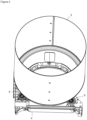
Figure 1 - is the perspective view of the household appliance related to an embodiment of the present invention. -
Figure 2 - is the partial view of the household appliance showing the bearing member, the wheel and the drum related to another embodiment of the present invention. -
Figure 3 - is the front view of the bearing member, the wheels and the drum where the wheels contact the drum related to another embodiment of the present invention. -
Figure 4 - is the view of the cross-section T-T shown inFigure 3 . -
Figure 5 - is the exploded view of the wheel, the shaft, the screw, the grounding line and the connection member related to an embodiment of the present invention. -
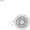
Figure 6 - is the front view of the wheel showing the wheel body, the outer body and the arm related to another embodiment of the present invention. - The elements illustrated in the figures are numbered as follows:
- 1- Household appliance
- 2- Body
- 3- Drum
- 4- Bearing member
- 5- Shaft
- 6- Wheel
- 7- Ball bearing
- 8- Conductive part
- 9- Grounding line
- 10- Outer body
- 11- Wheel body
- 12- Handle
- 13- Screw
- 14- Connection member
- The household appliance (1) comprises a body (2); a drum (3) which is disposed in the body (2), which is rotated around its own axis and which is suitable for loading the laundry therein; at least one bearing member (4) which provides the connection between the drum (3) and the body (2); at least one shaft (5) which is provided on the bearing member (4); at least one wheel (6) which is connected to the shaft (5), which supports the drum (3) by rotating together with the drum (3) and whereon the drum (3) is seated; and a ball bearing (7) which is provided on the wheel (6), which contacts the shaft (5) and which enables the wheel (6) to be rotatably connected to the shaft (5). The household appliance (1) is a laundry clothes dryer or a laundry washer/dryer, and the laundry to be dried and/or washed is loaded into the drum (3). The drum (3) is seated on the wheels (6) provided on the bearing member (4). The wheels (6) are attached to a plurality of shafts (5) provided on the bearing member (4). The shaft (5) does not move on the bearing member (4) and is manufactured as integrated with the bearing member (4) or so as to be attached and detached. When the drum (3) is rotated by a motor, the wheels (6) which contact the drum (3) also rotate around their own axis. By means of the ball bearing (7) which is provided on the wheel (6) and which provides the connection of the wheel (6) with the shaft (5), the wheel (6) is rotated on the shaft (5) in a more robust and noiseless manner.
- The household appliance (1) of the present invention comprises the drum (3), the ball bearing (7) and the shaft (5) which are manufactured from electrically conductive material; at least one conductive part (8) which is provided on the wheel (6) and which contacts the drum (3) and the ball bearing (7) to ensure electrical transmission from the drum (3) to the ball bearing (7); and at least one grounding line (9) which contacts the shaft (5) and which ensures that the electric charge transmitted from the conductive part (8) to the ball bearing (7) is grounded through the shaft (5). The drum (3) which is manufactured from sheet metal with a certain wall thickness conducts electricity. The voltage difference at two different points on the drum (3) causes electric current on the surface of the drum (3). The ball bearing (7) and the shaft (5) are generally manufactured from steel or plastic material with a certain electrical conductivity value. In order to ground the electricity on the surface of the drum (3), the conductive part (8) which contacts both the drum (3) and the ball bearing (7) is provided on the wheel (6). The conductive part (8) serves as an electrical transmission bridge between the drum (3) and the ball bearing (7). The electrical charge on the drum (3) is transmitted to the ball bearing (7) through the conductive part (8). Since the ball bearing (7) and the shaft (5) are in contact with each other, the electricity on the ball bearing (7) is transmitted to the shaft (5). There is at least one grounding line (9) which ensures that the electrical charge transmitted from the conductive part (8) to the ball bearing (7) is grounded through the shaft (5) in contact with the ball bearing (7). One end of the grounding line (9) is connected to the shaft (5) and the other end is connected to the body (2) of the household appliance (1) where the grounding process is performed. Thus, the drum (3) is grounded in a cost-efficient manner so as to provide the user with a safer and cheaper household appliance (1).
- In an embodiment of the present invention, at least one wheel body (11) manufactured from non-conductive material is provided on the wheel (3), and the conductive part (8) has at least one outer body (10) provided on the wheel (6) so as to contact the drum (3), and at least one arm (12) extending on the wheel body (11) so as to contact the outer body (10) and the ball bearing (7). The outer body (10), the wheel body (11) and the ball bearing (7) are arranged on the wheel (6) in this order. The outer body (10) has a cylindrical form and is manufactured from preferably EPDM rubber material with electrical conductivity value. Thus, damage which may occur as a result of the contact of the outer body (10) with the drum (3) is prevented. The wheel body (11) provides the structural connection of the outer body (10) and the ball bearing (7). The wheel body (11) is positioned between the outer body (10) and the ball bearing (7), and preferably has a cylindrical form. In order to reduce the production cost of the wheel (6) and to increase the resistance of the wheel (6) to the loads coming from the drum (3), the wheel body (11) is preferred to be manufactured from non-conductive plastic material. There is at least one arm (12) which extends on the wheel body (11) so as to ensure electrical transmission between the outer body (10) and the ball bearing (7). The electrical transmission is performed between the outer body (10) and the ball bearing (7) over the non-conductive wheel body (11) by means of the arm (12). Consequently, the strength of the wheel (7) against loads is increased and the production cost is reduced.
- In another embodiment of the present invention, the arm (12) is almost in the form of a rod. The arm (12) is positioned on the wheel body (11) so as to contact the outer body (10) and the ball bearing (7). In addition, the arm (12) can also be positioned in the wheel body (11). Since the arm (12) is in the form of a rod, the production method is facilitated and the production cost of the wheel (6) is reduced.
- In another embodiment of the present invention, the conductive part (8) and the wheel body (10) are manufactured as a single piece by the injection method.
- Plastic injection is preferred as the injection method. Thus, the conductive part (8), the arm (12), the outer body (10) and the wheel body (11) are manufactured in a very simple, easy and quick manner.
- In another embodiment of the present invention, the conductive part (8) completely surrounds the ball bearing (7). In this embodiment, instead of the outer body (10), the arm (12) and the wheel body (11) structure, the conductive part (8) is positioned in the part of the wheel (6) remaining between the ball bearing (7) and the drum (3). Thus, by increasing the surface area where the conductive part (8) contacts with the bearing (7), electricity is rapidly transmitted from the drum (3) to the ball bearing (7). Moreover, an alternative wheel (6) production embodiment is realized wherein the additional mold costs required to manufacture the arm (12) are reduced.
- In another embodiment of the present invention, there is a screw (13) which is manufactured from an electrically conductive material and which enables the shaft (5) to be fixed on the bearing member (4), and there is at least one connection member (14) which is provided on the grounding line (9) and which remains between the screw (13) and the shaft (5). In this embodiment, there is preferably a grooved part provided on the shaft (5), and there is a threaded part provided on a screw (13) and which engages with the grooved part so as to enable the shaft (5) to be fixed to the bearing member (4). The screw (13) is rotated by means of the screw head. The connection member (14) is fitted around the screw head. Then, by rotating the screw (13), the threaded part is inserted into the grooved part and the connection member (14) is enabled to be squeezed between the shaft (5) and the screw head. Thus, the electricity transmitted from the ball bearing (7) to the shaft (5) is transmitted from the shaft (5) to the grounding line (9) through the connection member (14) manufactured from an electrically conductive material so as to be grounded. Consequently, the grounding line (9) is prevented from leaving the shaft (5) over time and causing a safety risk.
- In another embodiment of the present invention, the connection member (14) is welded onto the shaft (5). By welding the connection member (14) onto the shaft (5), a permanent connection is obtained between the connection member (14) and the shaft (5).
- In another embodiment of the present invention, the household appliance (1) is a laundry dryer.
- By means of the present invention, a household appliance (1) is realized, wherein the safety is increased at an optimum level by ensuring that the electricity taken from the drum (3) via the conductive part (8) located on the wheel (6) is transmitted to the bearing (7), the shaft (5) and from there to the grounding line (9).
Claims (7)
- A household appliance (1) comprising a body (2); a drum (3) which is disposed in the body (2), which is rotated around its own axis and which is suitable for loading the laundry therein; at least one bearing member (4) which provides the connection between the drum (3) and the body (2); at least one shaft (5) which is provided on the bearing member (4); at least one wheel (6) which is connected to the shaft (5), which supports the drum (3) by rotating together with the drum (3) and whereon the drum (3) is seated; and a ball bearing (7) which is provided on the wheel (6), which contacts the shaft (5) and which enables the wheel (6) to be rotatably connected to the shaft (5), characterized by the drum (3), the ball bearing (7) and the shaft (5) which are manufactured from electrically conductive material; at least one conductive part (8) which is provided on the wheel (6) and which contacts the drum (3) and the ball bearing (7) to ensure electrical transmission from the drum (3) to the ball bearing (7); and at least one grounding line (9) which contacts the shaft (5) and which ensures that the electric charge transmitted from the conductive part (8) to the ball bearing (7) is grounded through the shaft (5).
- A household appliance (1) as in Claim 1, characterized by at least one wheel body (11) which is provided on the wheel (3) and which is manufactured from non-conductive material, and by the conductive part (8) which has at least one outer body (10) provided on the wheel (6) so as to contact the drum (3), and at least one arm (12) extending on the wheel body (11) so as to contact the outer body (10) and the ball bearing (7).
- A household appliance (1) as in any one of Claims 1 to 3, characterized by the conductive part (8) and the wheel body (10) which are manufactured as a single piece by the injection method.
- A household appliance (1) as in Claim 1, characterized by the conductive part (8) which completely surrounds the ball bearing (7).
- A household appliance (1) as in any one of the above claims, characterized by a screw (13) which is manufactured from an electrically conductive material and which enables the shaft (5) to be fixed on the bearing member (4), and by at least one connection member (14) which is provided on the grounding line (9) and which remains between the screw (13) and the shaft (5).
- A household appliance (1) as in Claim 1, characterized by the connection member (14) which is welded onto the shaft (5).
- A household appliance (1) as in any one of the above claims, which is a laundry dryer.
Applications Claiming Priority (1)
| Application Number | Priority Date | Filing Date | Title |
|---|---|---|---|
| TR202220691 | 2022-12-27 |
Publications (2)
| Publication Number | Publication Date |
|---|---|
| EP4394107A1 true EP4394107A1 (en) | 2024-07-03 |
| EP4394107B1 EP4394107B1 (en) | 2025-08-06 |
Family
ID=89029819
Family Applications (1)
| Application Number | Title | Priority Date | Filing Date |
|---|---|---|---|
| EP23213022.9A Active EP4394107B1 (en) | 2022-12-27 | 2023-11-29 | A household appliance |
Country Status (1)
| Country | Link |
|---|---|
| EP (1) | EP4394107B1 (en) |
Citations (7)
| Publication number | Priority date | Publication date | Assignee | Title |
|---|---|---|---|---|
| JPH09131494A (en) * | 1995-11-09 | 1997-05-20 | Toshiba Corp | Washing machine |
| EP1581683A1 (en) * | 2002-12-27 | 2005-10-05 | Arcel K A. . | Washing/drying machine |
| KR100610666B1 (en) | 2005-03-11 | 2006-08-09 | 삼성전자주식회사 | Drum Washing Machine |
| CN101314914A (en) | 2007-06-01 | 2008-12-03 | 海尔集团公司 | Dryer drum support |
| CN105220427A (en) | 2014-06-30 | 2016-01-06 | 无锡小天鹅股份有限公司 | Dryer |
| CN107503084A (en) * | 2017-09-20 | 2017-12-22 | 无锡小天鹅股份有限公司 | Clothes treatment device |
| CN111576001A (en) * | 2019-02-18 | 2020-08-25 | 青岛海尔洗衣机有限公司 | Wall-mounted clothes treatment equipment |
-
2023
- 2023-11-29 EP EP23213022.9A patent/EP4394107B1/en active Active
Patent Citations (7)
| Publication number | Priority date | Publication date | Assignee | Title |
|---|---|---|---|---|
| JPH09131494A (en) * | 1995-11-09 | 1997-05-20 | Toshiba Corp | Washing machine |
| EP1581683A1 (en) * | 2002-12-27 | 2005-10-05 | Arcel K A. . | Washing/drying machine |
| KR100610666B1 (en) | 2005-03-11 | 2006-08-09 | 삼성전자주식회사 | Drum Washing Machine |
| CN101314914A (en) | 2007-06-01 | 2008-12-03 | 海尔集团公司 | Dryer drum support |
| CN105220427A (en) | 2014-06-30 | 2016-01-06 | 无锡小天鹅股份有限公司 | Dryer |
| CN107503084A (en) * | 2017-09-20 | 2017-12-22 | 无锡小天鹅股份有限公司 | Clothes treatment device |
| CN111576001A (en) * | 2019-02-18 | 2020-08-25 | 青岛海尔洗衣机有限公司 | Wall-mounted clothes treatment equipment |
Also Published As
| Publication number | Publication date |
|---|---|
| EP4394107B1 (en) | 2025-08-06 |
Similar Documents
| Publication | Publication Date | Title |
|---|---|---|
| EP1826310B1 (en) | Steam generator and drum-type washing machine with the same | |
| US20080148785A1 (en) | Washing Machine | |
| US9683324B2 (en) | Fans-motor assembly for condenser laundry dryer machine and condenser laundry dryer machine comprising said assembly | |
| EP1915480B1 (en) | Drying duct assembly and washing machine having the same | |
| US10087564B2 (en) | Laundry treatment apparatus | |
| EP2302125A1 (en) | Washing machine with improved heating system | |
| CN104233696A (en) | Single-tub pulsator washing machine and assorted removable spin-dry basket | |
| KR101537092B1 (en) | Laundry processing equipment | |
| EP4394107B1 (en) | A household appliance | |
| CN118186718A (en) | Device for supplying power inside drum washing machine barrel and washing machine | |
| CN109563665A (en) | Washing machine | |
| CN107503084B (en) | Clothes treating apparatus | |
| CN105088621A (en) | Roller washing machine | |
| CN1950561B (en) | Inclined drum washing machine with pulsator and control method thereof | |
| EP2270273B1 (en) | Washing machine | |
| EP1619285B2 (en) | Basket for washing machine, washer-drier, drier, and the like | |
| US3457656A (en) | Laundry apparatus | |
| EP2521809B1 (en) | Top loading laundry washing machine | |
| TR2022020691A2 (en) | A HOME APPLIANCE | |
| CN215598019U (en) | Intelligent textile oven capable of controlling temperature | |
| US3059203A (en) | Collector ring structure | |
| CN216338590U (en) | Clothes treatment device | |
| KR101236691B1 (en) | Drum washing machine | |
| CN111118830A (en) | A washing machine and its control method | |
| CN101451303B (en) | Roller earthing structure of dryer |
Legal Events
| Date | Code | Title | Description |
|---|---|---|---|
| PUAI | Public reference made under article 153(3) epc to a published international application that has entered the european phase |
Free format text: ORIGINAL CODE: 0009012 |
|
| STAA | Information on the status of an ep patent application or granted ep patent |
Free format text: STATUS: REQUEST FOR EXAMINATION WAS MADE |
|
| 17P | Request for examination filed |
Effective date: 20231129 |
|
| AK | Designated contracting states |
Kind code of ref document: A1 Designated state(s): AL AT BE BG CH CY CZ DE DK EE ES FI FR GB GR HR HU IE IS IT LI LT LU LV MC ME MK MT NL NO PL PT RO RS SE SI SK SM TR |
|
| GRAP | Despatch of communication of intention to grant a patent |
Free format text: ORIGINAL CODE: EPIDOSNIGR1 |
|
| STAA | Information on the status of an ep patent application or granted ep patent |
Free format text: STATUS: GRANT OF PATENT IS INTENDED |
|
| RIC1 | Information provided on ipc code assigned before grant |
Ipc: H01R 4/64 20060101ALN20250206BHEP Ipc: D06F 58/06 20060101ALN20250206BHEP Ipc: D06F 58/20 20060101ALI20250206BHEP Ipc: D06F 37/42 20060101AFI20250206BHEP |
|
| INTG | Intention to grant announced |
Effective date: 20250303 |
|
| RIN1 | Information on inventor provided before grant (corrected) |
Inventor name: SAR, CAN Inventor name: UYANIK, MURAT Inventor name: CIN, ENGIN Inventor name: SELCUK, CEM |
|
| GRAS | Grant fee paid |
Free format text: ORIGINAL CODE: EPIDOSNIGR3 |
|
| GRAA | (expected) grant |
Free format text: ORIGINAL CODE: 0009210 |
|
| STAA | Information on the status of an ep patent application or granted ep patent |
Free format text: STATUS: THE PATENT HAS BEEN GRANTED |
|
| AK | Designated contracting states |
Kind code of ref document: B1 Designated state(s): AL AT BE BG CH CY CZ DE DK EE ES FI FR GB GR HR HU IE IS IT LI LT LU LV MC ME MK MT NL NO PL PT RO RS SE SI SK SM TR |
|
| REG | Reference to a national code |
Ref country code: GB Ref legal event code: FG4D |
|
| REG | Reference to a national code |
Ref country code: CH Ref legal event code: EP |
|
| REG | Reference to a national code |
Ref country code: IE Ref legal event code: FG4D |
|
| REG | Reference to a national code |
Ref country code: DE Ref legal event code: R096 Ref document number: 602023005466 Country of ref document: DE |
|
| PGFP | Annual fee paid to national office [announced via postgrant information from national office to epo] |
Ref country code: TR Payment date: 20250918 Year of fee payment: 3 |
|
| REG | Reference to a national code |
Ref country code: NL Ref legal event code: MP Effective date: 20250806 |
|
| PG25 | Lapsed in a contracting state [announced via postgrant information from national office to epo] |
Ref country code: IS Free format text: LAPSE BECAUSE OF FAILURE TO SUBMIT A TRANSLATION OF THE DESCRIPTION OR TO PAY THE FEE WITHIN THE PRESCRIBED TIME-LIMIT Effective date: 20251206 |
|
| PGFP | Annual fee paid to national office [announced via postgrant information from national office to epo] |
Ref country code: DE Payment date: 20251119 Year of fee payment: 3 |
|
| PG25 | Lapsed in a contracting state [announced via postgrant information from national office to epo] |
Ref country code: NO Free format text: LAPSE BECAUSE OF FAILURE TO SUBMIT A TRANSLATION OF THE DESCRIPTION OR TO PAY THE FEE WITHIN THE PRESCRIBED TIME-LIMIT Effective date: 20251106 |
|
| REG | Reference to a national code |
Ref country code: LT Ref legal event code: MG9D |
|
| PG25 | Lapsed in a contracting state [announced via postgrant information from national office to epo] |
Ref country code: PT Free format text: LAPSE BECAUSE OF FAILURE TO SUBMIT A TRANSLATION OF THE DESCRIPTION OR TO PAY THE FEE WITHIN THE PRESCRIBED TIME-LIMIT Effective date: 20251209 |
|
| PG25 | Lapsed in a contracting state [announced via postgrant information from national office to epo] |
Ref country code: FI Free format text: LAPSE BECAUSE OF FAILURE TO SUBMIT A TRANSLATION OF THE DESCRIPTION OR TO PAY THE FEE WITHIN THE PRESCRIBED TIME-LIMIT Effective date: 20250806 |
|
| PGFP | Annual fee paid to national office [announced via postgrant information from national office to epo] |
Ref country code: IT Payment date: 20251201 Year of fee payment: 3 |
|
| PG25 | Lapsed in a contracting state [announced via postgrant information from national office to epo] |
Ref country code: NL Free format text: LAPSE BECAUSE OF FAILURE TO SUBMIT A TRANSLATION OF THE DESCRIPTION OR TO PAY THE FEE WITHIN THE PRESCRIBED TIME-LIMIT Effective date: 20250806 Ref country code: HR Free format text: LAPSE BECAUSE OF FAILURE TO SUBMIT A TRANSLATION OF THE DESCRIPTION OR TO PAY THE FEE WITHIN THE PRESCRIBED TIME-LIMIT Effective date: 20250806 |
|
| PG25 | Lapsed in a contracting state [announced via postgrant information from national office to epo] |
Ref country code: GR Free format text: LAPSE BECAUSE OF FAILURE TO SUBMIT A TRANSLATION OF THE DESCRIPTION OR TO PAY THE FEE WITHIN THE PRESCRIBED TIME-LIMIT Effective date: 20251107 |
|
| PG25 | Lapsed in a contracting state [announced via postgrant information from national office to epo] |
Ref country code: SE Free format text: LAPSE BECAUSE OF FAILURE TO SUBMIT A TRANSLATION OF THE DESCRIPTION OR TO PAY THE FEE WITHIN THE PRESCRIBED TIME-LIMIT Effective date: 20250806 |
|
| PG25 | Lapsed in a contracting state [announced via postgrant information from national office to epo] |
Ref country code: LV Free format text: LAPSE BECAUSE OF FAILURE TO SUBMIT A TRANSLATION OF THE DESCRIPTION OR TO PAY THE FEE WITHIN THE PRESCRIBED TIME-LIMIT Effective date: 20250806 |
|
| PG25 | Lapsed in a contracting state [announced via postgrant information from national office to epo] |
Ref country code: PL Free format text: LAPSE BECAUSE OF FAILURE TO SUBMIT A TRANSLATION OF THE DESCRIPTION OR TO PAY THE FEE WITHIN THE PRESCRIBED TIME-LIMIT Effective date: 20250806 Ref country code: BG Free format text: LAPSE BECAUSE OF FAILURE TO SUBMIT A TRANSLATION OF THE DESCRIPTION OR TO PAY THE FEE WITHIN THE PRESCRIBED TIME-LIMIT Effective date: 20250806 |
|
| PG25 | Lapsed in a contracting state [announced via postgrant information from national office to epo] |
Ref country code: RS Free format text: LAPSE BECAUSE OF FAILURE TO SUBMIT A TRANSLATION OF THE DESCRIPTION OR TO PAY THE FEE WITHIN THE PRESCRIBED TIME-LIMIT Effective date: 20251106 |
|
| PG25 | Lapsed in a contracting state [announced via postgrant information from national office to epo] |
Ref country code: ES Free format text: LAPSE BECAUSE OF FAILURE TO SUBMIT A TRANSLATION OF THE DESCRIPTION OR TO PAY THE FEE WITHIN THE PRESCRIBED TIME-LIMIT Effective date: 20250806 |
|
| REG | Reference to a national code |
Ref country code: AT Ref legal event code: MK05 Ref document number: 1821935 Country of ref document: AT Kind code of ref document: T Effective date: 20250806 |
|
| PG25 | Lapsed in a contracting state [announced via postgrant information from national office to epo] |
Ref country code: RO Free format text: LAPSE BECAUSE OF FAILURE TO SUBMIT A TRANSLATION OF THE DESCRIPTION OR TO PAY THE FEE WITHIN THE PRESCRIBED TIME-LIMIT Effective date: 20250806 |
|
| PG25 | Lapsed in a contracting state [announced via postgrant information from national office to epo] |
Ref country code: SM Free format text: LAPSE BECAUSE OF FAILURE TO SUBMIT A TRANSLATION OF THE DESCRIPTION OR TO PAY THE FEE WITHIN THE PRESCRIBED TIME-LIMIT Effective date: 20250806 |
|
| PG25 | Lapsed in a contracting state [announced via postgrant information from national office to epo] |
Ref country code: DK Free format text: LAPSE BECAUSE OF FAILURE TO SUBMIT A TRANSLATION OF THE DESCRIPTION OR TO PAY THE FEE WITHIN THE PRESCRIBED TIME-LIMIT Effective date: 20250806 |
|
| PG25 | Lapsed in a contracting state [announced via postgrant information from national office to epo] |
Ref country code: AT Free format text: LAPSE BECAUSE OF FAILURE TO SUBMIT A TRANSLATION OF THE DESCRIPTION OR TO PAY THE FEE WITHIN THE PRESCRIBED TIME-LIMIT Effective date: 20250806 |
|
| PG25 | Lapsed in a contracting state [announced via postgrant information from national office to epo] |
Ref country code: CZ Free format text: LAPSE BECAUSE OF FAILURE TO SUBMIT A TRANSLATION OF THE DESCRIPTION OR TO PAY THE FEE WITHIN THE PRESCRIBED TIME-LIMIT Effective date: 20250806 |
|
| PG25 | Lapsed in a contracting state [announced via postgrant information from national office to epo] |
Ref country code: SK Free format text: LAPSE BECAUSE OF FAILURE TO SUBMIT A TRANSLATION OF THE DESCRIPTION OR TO PAY THE FEE WITHIN THE PRESCRIBED TIME-LIMIT Effective date: 20250806 Ref country code: EE Free format text: LAPSE BECAUSE OF FAILURE TO SUBMIT A TRANSLATION OF THE DESCRIPTION OR TO PAY THE FEE WITHIN THE PRESCRIBED TIME-LIMIT Effective date: 20250806 |
|
| REG | Reference to a national code |
Ref country code: DE Ref legal event code: R097 Ref document number: 602023005466 Country of ref document: DE |
|
| PLBE | No opposition filed within time limit |
Free format text: ORIGINAL CODE: 0009261 |
|
| STAA | Information on the status of an ep patent application or granted ep patent |
Free format text: STATUS: NO OPPOSITION FILED WITHIN TIME LIMIT |
|
| REG | Reference to a national code |
Ref country code: CH Ref legal event code: L10 Free format text: ST27 STATUS EVENT CODE: U-0-0-L10-L00 (AS PROVIDED BY THE NATIONAL OFFICE) Effective date: 20260617 |
|
| PG25 | Lapsed in a contracting state [announced via postgrant information from national office to epo] |
Ref country code: LT Free format text: LAPSE BECAUSE OF FAILURE TO SUBMIT A TRANSLATION OF THE DESCRIPTION OR TO PAY THE FEE WITHIN THE PRESCRIBED TIME-LIMIT Effective date: 20250806 Ref country code: MC Free format text: LAPSE BECAUSE OF FAILURE TO SUBMIT A TRANSLATION OF THE DESCRIPTION OR TO PAY THE FEE WITHIN THE PRESCRIBED TIME-LIMIT Effective date: 20250806 |
|
| 26N | No opposition filed |
Effective date: 20260507 |
|
| PG25 | Lapsed in a contracting state [announced via postgrant information from national office to epo] |
Ref country code: LU Free format text: LAPSE BECAUSE OF NON-PAYMENT OF DUE FEES Effective date: 20251129 |