EP4393867A1 - Telescopic handler - Google Patents
Telescopic handler Download PDFInfo
- Publication number
- EP4393867A1 EP4393867A1 EP23217792.3A EP23217792A EP4393867A1 EP 4393867 A1 EP4393867 A1 EP 4393867A1 EP 23217792 A EP23217792 A EP 23217792A EP 4393867 A1 EP4393867 A1 EP 4393867A1
- Authority
- EP
- European Patent Office
- Prior art keywords
- valve
- hydraulic
- chamber
- energized
- arm
- Prior art date
- Legal status (The legal status is an assumption and is not a legal conclusion. Google has not performed a legal analysis and makes no representation as to the accuracy of the status listed.)
- Granted
Links
Images

Classifications
-
- B—PERFORMING OPERATIONS; TRANSPORTING
- B66—HOISTING; LIFTING; HAULING
- B66F—HOISTING, LIFTING, HAULING OR PUSHING, NOT OTHERWISE PROVIDED FOR, e.g. DEVICES WHICH APPLY A LIFTING OR PUSHING FORCE DIRECTLY TO THE SURFACE OF A LOAD
- B66F9/00—Devices for lifting or lowering bulky or heavy goods for loading or unloading purposes
- B66F9/06—Devices for lifting or lowering bulky or heavy goods for loading or unloading purposes movable, with their loads, on wheels or the like, e.g. fork-lift trucks
- B66F9/075—Constructional features or details
- B66F9/20—Means for actuating or controlling masts, platforms, or forks
- B66F9/22—Hydraulic devices or systems
Definitions
- the present invention relates to the field of telescopic lift vehicles named "Telescopic handler” or "telehandler”.
- Telehandler vehicles are also widely used in the construction sector to allow loads to be lifted even up to the third or fourth floor of a building, without the need to install a crane.
- the object of the present invention is to simplify the control of a telescopic arm of a lifting vehicle.
- Figure 1 shows a telehandler vehicle VEH object of the present invention.
- It comprises a telescopic arm B arranged to raise and lower under the action of an actuator HA, shown in figure 2 .
- a hydraulic pump (not shown) is arranged to be driven in rotation by a prime mover (not shown), generally an internal combustion and preferably a Diesel or Otto cycle engine.
- the hydraulic pump is also arranged to supply the actuator HA at least in the operating conditions where this is required.
- An electro-hydraulic circuit HC controls the inflow and outflow of hydraulic oil to and from the HA hydraulic actuator.
- the oil that flows out is generally collected in an accumulation tank T, from which the same oil is recirculated in the hydraulic circuit by the action of the hydraulic pump, which is therefore unidirectional. This is true regardless of the valve V is an open or closed center directional valve.
- the accumulation tank is at atmospheric pressure, but it may also be pressurizable.
- the hydraulic actuator is double action, therefore it includes two opposing chambers HA1 and HA2 which oppositely fill and empty to allow the lifting and lowering of the telescopic arm A.
- the filling of the first chamber HA1 is associated with the extraction of the hydraulic actuator stem.
- the extraction of the stem SM is associated with the lifting of the arm A of the vehicle.
- a kinematic configuration may be provided which allows for the boom to rise in response to the retraction of the hydraulic actuator stem.
- the circuit is also equipped with a damping reservoir HST and a first valve V1 operationally connected between the first actuator chamber HA1 and the damping reservoir HST. It is arranged to assume two positions:
- the bidirectional connection of the chamber HA1 with the damping reservoir allows to dampen the arm B. This is particularly useful when the vehicle moves on rough ground carrying a load.
- the damping applied to the arm prevents the stresses deriving from the roughness of the ground from being abruptly transferred to the load.
- the damping tank HST is connected to the first chamber HA1 of the hydraulic actuator by means of a check valve, which allows the damping tank to be pressurized to the same pressure as the first chamber HA1 of the hydraulic actuator.
- a check valve which allows, regardless of the condition of the first valve V1, to have the same pressurization degree in the two components. Therefore, when, at the end of the lifting of the arm, the first valve V1 is energized, the arm remains approximately in the same position with the advantages described above.
- both the first chamber HA1 and the damping reservoir can discharge the hydraulic oil into the accumulator tank T. This fact ensures that the damping reservoir is always kept at the same pressurization level as the first chamber HA1 of the hydraulic actuator.
- the third valve V3, is energized simultaneously with the second valve V2.
- V V1 V2 V3 C1 Vb ON OFF OFF C2 Vc OFF ON OFF C3 Vb OFF ON ON ON C1 the arm is raised to a fixed height and damped
- C2 the boom is actuated in lowering with the contribution of the hydraulic pump and the recirculation of hydraulic oil between the chambers of the same hydraulic actuator and of the accumulation tank T
- C3 the boom is fully lowered and the two valves V2 and V3 are energized, while the valves V and V1 are de-energized, allowing the boom to move up and down freely.
Landscapes
- Engineering & Computer Science (AREA)
- Transportation (AREA)
- Structural Engineering (AREA)
- Chemical & Material Sciences (AREA)
- Combustion & Propulsion (AREA)
- Civil Engineering (AREA)
- Life Sciences & Earth Sciences (AREA)
- Geology (AREA)
- Mechanical Engineering (AREA)
- Forklifts And Lifting Vehicles (AREA)
- Fluid-Pressure Circuits (AREA)
Abstract
- a one-way hydraulic pump arranged to be rotated by a prime mover,
- a hydraulic oil accumulation tank (T),
- a damping tank (HST),
- a double-action hydraulic actuator (HA), comprising a first chamber (HA1), for lifting the arm (B), and a second chamber (HA2), for lowering the arm, opposite the first, arranged to be hydraulically powered by
- a hydraulic circuit (HC) comprising
+ a proportional main valve (V) , arranged to assume a rest position (Vb) in which the hydraulic circuit is isolated from both the hydraulic pump and the accumulation tank (T), and a first actuation position (Vc), to connect the second chamber (HA2) of the hydraulic actuator with the hydraulic pump (P) and the first chamber (HA1) of the hydraulic actuator with the buffer tank (T),
+ a first valve (V1) arranged to assume at least one energized position (Vlb), in which it allows bidirectional communication between the hydraulic damping reservoir (HST) and the first chamber (HA1) of the hydraulic actuator,
+ a second valve (V2) arranged to assume an energized position (V2b), in which it allows a bidirectional circulation of the hydraulic oil between the two chambers;
the vehicle comprising processing means (ECU) configured to perform
- a first operating configuration (C1) in which said first valve (V1) is energized (ON) and said second valve (V2) is de-energized (OFF) when said main valve (V) is in rest position (Vb) and the arm is raised,
- a second operating configuration (C2) in which said second valve (V2) is energized and said first valve (V1) is de-energized when said main valve (V) is in said first actuation position (Vc).
Description
- The present invention relates to the field of telescopic lift vehicles named "Telescopic handler" or "telehandler".
- Telescopic booms are widely used in the field of work machines, especially in mining companies, where the work telescopic boom plays an important role in the field of material loading operations.
- Telescopic arms are also used in firefighting vehicles for rescuing people.
- Telehandler vehicles are also widely used in the construction sector to allow loads to be lifted even up to the third or fourth floor of a building, without the need to install a crane.
- The arm comprises a plurality of interconnected segments, wherein the first segment is hinged to the chassis of the work vehicle.
- The vehicle can be used to perform various operations and therefore it is important that the hydraulic actuation system is suitable to make versatile the vehicle.
- Unless specifically excluded in the detailed description that follows, what is described in this chapter is to be considered as an integral part of the detailed description.
- The object of the present invention is to simplify the control of a telescopic arm of a lifting vehicle.
- The basic idea of the present invention is that of realizing a cushioned lifting condition and a rapid descent condition selected on the basis of predetermined preconditions. The invention is better described with the aid of claim 1.
- The dependent claims describe preferred variants of the invention, forming an integral part of the present description.
- Further objects and advantages of the present invention will become clear from the detailed description that follows of an embodiment of the same (and of its variants) and from the annexed drawings given for purely explanatory and non-limiting purposes, in which:
-
Fig. 1 shows an example of a telescopic lifting vehicle modified according to the present invention; -
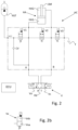
Fig. 2 shows an electro-hydraulic circuit object of the present invention e -
Fig.2b shows a detail of the operating configurations that can be assumed by the valves shown in the circuit ofFig. 2 . - The same reference numbers and letters in the figures identify the same elements or components or functions.
- It should also be noted that the terms "first", "second", "third", "superior", "inferior" and the like may be used herein to distinguish various elements. These terms do not imply a spatial, sequential, or hierarchical order for the modified items unless specifically indicated or inferred from the text.
- The elements and characteristics illustrated in the various preferred embodiments, including the drawings, can be combined with each other without however departing from the scope of protection of the present application as described below.
-
Figure 1 shows a telehandler vehicle VEH object of the present invention. - It comprises a telescopic arm B arranged to raise and lower under the action of an actuator HA, shown in
figure 2 . - A hydraulic pump (not shown) is arranged to be driven in rotation by a prime mover (not shown), generally an internal combustion and preferably a Diesel or Otto cycle engine.
- The hydraulic pump is also arranged to supply the actuator HA at least in the operating conditions where this is required.
- An electro-hydraulic circuit HC controls the inflow and outflow of hydraulic oil to and from the HA hydraulic actuator.
- The oil that flows out is generally collected in an accumulation tank T, from which the same oil is recirculated in the hydraulic circuit by the action of the hydraulic pump, which is therefore unidirectional. This is true regardless of the valve V is an open or closed center directional valve.
- Generally, the accumulation tank is at atmospheric pressure, but it may also be pressurizable.
- The hydraulic actuator is double action, therefore it includes two opposing chambers HA1 and HA2 which oppositely fill and empty to allow the lifting and lowering of the telescopic arm A.
- For convenience, the filling of the first chamber HA1 is associated with the extraction of the hydraulic actuator stem. In the same way, only for convenience, the extraction of the stem SM is associated with the lifting of the arm A of the vehicle. However, a kinematic configuration may be provided which allows for the boom to rise in response to the retraction of the hydraulic actuator stem.
- A proportional main valve V has three positions:
- a rest position, represented by a central drawer Vb, in
figure 2 , in which the hydraulic circuit HC is isolated both from the hydraulic pump and from the accumulation tank T, - a first actuation position Va, in which a first chamber, HA1 of the hydraulic actuator HA is operatively connected with the hydraulic pump P, while the second chamber HA2 of the hydraulic actuator, opposite the first chamber, is connected to the accumulation tank T,
- a second actuation position Vc, in which the second chamber HA2 of the hydraulic actuator is operatively connected to the hydraulic pump (P) while the first chamber HA1 is connected to the accumulation tank T.
- It is worth pointing out that, although the hydraulic pump is not shown in the drawings, the main valve V has a port designated by the letter P to indicate that such port is operationally connected with the hydraulic pump. The same applies to the port connected to the hydraulic tank T.
- The circuit is also equipped with a damping reservoir HST and a first valve V1 operationally connected between the first actuator chamber HA1 and the damping reservoir HST. It is arranged to assume two positions:
- a first position V1a, rest position, in which it allows the flow of hydraulic oil only from the hydraulic tank HST to the first chamber HA1 of the hydraulic actuator and
- a second position V1b, energized, in which it allows bidirectional communication between the hydraulic tank HST and the first chamber HA1 of the hydraulic actuator.
- Valve V1 as well as the other valves V2 and V3 are summarized in
figure 2b , where "x" can assume the value 1, 2 or 3. -
Figure 2b indicates the first position Vxa and the second position Vxb. The respective reference signs are not directly shown infigure 2 in order not to complicate their reading. - Therefore, when the valve V1 is energized, the bidirectional connection of the chamber HA1 with the damping reservoir allows to dampen the arm B. This is particularly useful when the vehicle moves on rough ground carrying a load. In particular, the damping applied to the arm prevents the stresses deriving from the roughness of the ground from being abruptly transferred to the load.
- The damping reservoir is a per se known device. It may include a diaphragm partially filled with air or another compressible fluid, which allows hydraulic pressure peaks in the circuit to discharge onto the compressible fluid.
- According to a preferred aspect of the present invention, the damping tank HST is connected to the first chamber HA1 of the hydraulic actuator by means of a check valve, which allows the damping tank to be pressurized to the same pressure as the first chamber HA1 of the hydraulic actuator. This fact allows, regardless of the condition of the first valve V1, to have the same pressurization degree in the two components. Therefore, when, at the end of the lifting of the arm, the first valve V1 is energized, the arm remains approximately in the same position with the advantages described above. On the contrary, if the reservoir were not pressurized in the same way as the first chamber HA1, once the first valve V1 is energized there would be a concrete risk that part of the hydraulic oil contained in the first chamber would flow into the damping reservoir with a significant lowering of the arm and with the risk of damage to property and people.
- Valve V1, in the rest condition, allows the circulation of hydraulic oil from the damping reservoir to the remaining circuit. This fact is very useful when the valve V is in the position Vc, i.e. in which it causes the arm to lower and empty the first chamber HA1.
- In fact, under these conditions, both the first chamber HA1 and the damping reservoir can discharge the hydraulic oil into the accumulator tank T. This fact ensures that the damping reservoir is always kept at the same pressurization level as the first chamber HA1 of the hydraulic actuator.
- The circuit includes a second valve V2 operatively connected between the two chambers HA1 and HA2 of the hydraulic actuator HA. It is arranged to assume two positions:
- a first position V2a, rest position, in which it prevents any circulation of hydraulic oil between the two actuator chambers;
- a second position V2b, energized, in which it allows a bidirectional circulation of the hydraulic oil between the two chambers.
- The second valve V2 can be of the proportional type allowing the regulation of the bidirectional circulation of the hydraulic oil. In other words, a partial throttling is realized proportional to the excitation of the valve.
- This second position is particularly useful when it is desired to lower the arm. In fact, in addition to the contribution of the hydraulic pump, which is operatively connected to the second chamber HA2, the first chamber contributes by sending the hydraulic oil to the first chamber instead of sending it to the accumulation tank T.
- According to a preferred aspect of the present invention, the hydraulic circuit HC comprises a third valve V3 operatively connected between the second chamber HA2 of the hydraulic actuator and the accumulation tank T.
- It is arranged to assume two positions:
- a first position V3a, rest position, in which it allows the circulation of hydraulic oil only from the accumulation tank T to the second chamber and
- a second position V3b, energized, in which it allows the bidirectional circulation of the oil between the second chamber HA2 of the hydraulic actuator HA and the accumulation tank.
- The third valve V3, according to an operating condition, is energized simultaneously with the second valve V2.
- This fact allows both chambers of the hydraulic actuator to be connected to each other and to the accumulation tank T. Therefore, arm B is free to move under the effect of its own weight force.
- This operating condition is particularly useful since it is possible to associate a tool such as a brush for cleaning the ground to the end of the arm and the arm, being free to oscillate, can freely follow the contours of the ground without the risk of damaging the tool.
- It is worth pointing out that the rest position of the third valve V3 is also useful when only the valve V2 is energized, since three contributions of hydraulic oil flow into the second chamber HA2:
- oil coming from the first chamber HA1,
- oil coming from hydraulic pump P,
- oil coming from the accumulation tank T.
- Therefore, the implementation of the third valve results in synergy with the second valve both when the latter is in the rest position and in the energized condition.
- The following operating conditions have been considered up to now:
V V1 V2 V3 C1 Vb ON OFF OFF C2 Vc OFF ON OFF C3 Vb OFF ON ON C1: the arm is raised to a fixed height and damped,
C2: the boom is actuated in lowering with the contribution of the hydraulic pump and the recirculation of hydraulic oil between the chambers of the same hydraulic actuator and of the accumulation tank T,
C3: the boom is fully lowered and the two valves V2 and V3 are energized, while the valves V and V1 are de-energized, allowing the boom to move up and down freely. - It is worth highlighting that the third valve V3 can
- not exist, or
- be replaced by a check valve arranged to allow the flow of hydraulic oil exclusively from the hydraulic reservoir to the second chamber HA2 of the hydraulic actuator,
- Conversely, when the third valve is present and energized, then condition C3 can occur.
- It is important to highlight that the valves can assume "positions" considering that they have a mobile shutter. Each position corresponds to an "operating condition", therefore it is completely indifferent to confuse the terms "position" and "condition".
- An ECU processing unit is suitably configured to control the operation of the hydraulic pump and of the valves V, V1, V2, V3.
- In particular, a man/machine interface, operationally connected with the processing unit to activate one of the operating conditions C1 - C3, in relation to the vehicle's mission.
- For example, valve V1 can be energized automatically when an arm control lever, usually a joystick, is fully released, which corresponds to the Vb position of the V valve.
- For example, with the boom fully lowered, valves V2 and V3 can be automatically energized when the boom control lever is fully released, which corresponds to the Vb position of the V valve, and the arm is raised.
- Conversely, as soon as the joystick control lever is operated to obtain boom lifting, which corresponds to the Va position of the V valve, the V1 - V3 valves are automatically de-energized, returning to the rest condition.
- For example, when the joystick control lever is actuated to achieve boom lowering, which corresponds to the Vc position of the V valve, the second valve V2 is automatically energized to achieve faster boom lowering.
- The present invention can advantageously be implemented through a computer program comprising coding means for carrying out one or more steps of the method, when this program is executed on a computer. Therefore, it is understood that the scope of protection extends to said computer program and also to computer-readable means comprising a recorded message, said computer-readable means comprising program coding means for carrying out one or more steps of the method, when said program is run on a computer.
- Variants of the non-limiting example described are possible, without however departing from the scope of protection of the present invention, including all equivalent embodiments for a person skilled in the art, to the contents of the claims.
- From the description given above, the person skilled in the art is capable of realizing the object of the invention without introducing further constructive details.
Claims (5)
- Telescopic lift vehicle comprising an arm (B) hydraulically operated in elevation by means of- a one-way hydraulic pump arranged to be rotated by a prime mover,- a hydraulic oil accumulation tank (T),- a damping tank (HST),- a double-action hydraulic actuator (HA), comprising a first chamber (HA1), for lifting the arm (B), and a second chamber (HA2), for lowering the arm, opposite the first, arranged to be hydraulically powered by- a hydraulic circuit (HC) comprising+ a proportional main valve (V), arranged to assume a rest position (Vb) in which the hydraulic circuit is isolated from both the hydraulic pump and the accumulation tank (T), and a first actuation position (Vc), to connect the second chamber (HA2) of the hydraulic actuator with the hydraulic pump (P) and the first chamber (HA1) of the hydraulic actuator with the buffer tank (T),+ a first valve (V1) arranged to assume at least one energized position (V1b), in which it allows bidirectional communication between the hydraulic damping reservoir (HST) and the first chamber (HA1) of the hydraulic actuator,+ a second valve (V2) arranged to assume an energized position (V2b), in which it allows a bidirectional circulation of the hydraulic oil between the two chambers;the vehicle comprising processing means (ECU) configured to perform- a first operating configuration (C1) in which said first valve (V1) is energized (ON) and said second valve (V2) is de-energized (OFF) when said main valve (V) is in rest position (Vb) and the arm is raised,- a second operating configuration (C2) in which said second valve (V2) is energized and said first valve (V1) is de-energized when said main valve (V) is in said first actuation position (Vc).
- Vehicle according to claim 1, wherein said hydraulic circuit (HC) further comprises a check valve (V3a) arranged to allow the circulation of hydraulic oil only from the accumulation tank (T) to the second chamber (HA2), in so that the second chamber is simultaneously fed by the first chamber, the hydraulic pump and the accumulation tank.
- Vehicle according to claim 2, further comprising a third valve (V2) arranged to assume two positions:- a first position (V3a), rest position, in which it defines said check valve e- a second position (V3b), energized, in which it allows the bidirectional circulation of the oil between the second chamber (HA2) of the hydraulic actuator (HA) and the accumulation tank,and wherein said processing means are configured to keep said third valve de-energized in said first operating condition (C1).
- Vehicle according to claim 3, wherein said processing means are configured to realize a third operating configuration (C3), wherein said second and third valves are energized and said main valve and first valve are de-energized, so that the arm can rise and fall freely.
- Vehicle according to any one of the preceding claims, wherein said main valve (V) is further arranged to assume a second actuation condition (Va), to connect the first chamber (HA1) of the hydraulic actuator with the hydraulic pump (P) and the second chamber (HA2) of the hydraulic actuator with the accumulation tank (T) and in which said processing means are configured to de-energize said first, second and third valves when said main valve is in said second actuation condition (Va).
Applications Claiming Priority (1)
| Application Number | Priority Date | Filing Date | Title |
|---|---|---|---|
| IT102022000026805A IT202200026805A1 (en) | 2022-12-23 | 2022-12-23 | TELESCOPIC LIFT VEHICLE |
Publications (2)
| Publication Number | Publication Date |
|---|---|
| EP4393867A1 true EP4393867A1 (en) | 2024-07-03 |
| EP4393867B1 EP4393867B1 (en) | 2025-11-26 |
Family
ID=85380858
Family Applications (1)
| Application Number | Title | Priority Date | Filing Date |
|---|---|---|---|
| EP23217792.3A Active EP4393867B1 (en) | 2022-12-23 | 2023-12-18 | Telescopic handler |
Country Status (2)
| Country | Link |
|---|---|
| EP (1) | EP4393867B1 (en) |
| IT (1) | IT202200026805A1 (en) |
Citations (3)
| Publication number | Priority date | Publication date | Assignee | Title |
|---|---|---|---|---|
| US20080028924A1 (en) * | 2006-08-02 | 2008-02-07 | Stephenson Dwight B | Hydraulic System With A Cylinder Isolation Valve |
| ES2639340T3 (en) * | 2012-04-11 | 2017-10-26 | Clark Equipment Company | Lifting arm suspension system for a motorized machine |
| US20210062832A1 (en) * | 2018-05-07 | 2021-03-04 | Hydac Mobilhydraulik Gmbh | Valve arrangement for pressure medium supply of a hydraulic consumer |
-
2022
- 2022-12-23 IT IT102022000026805A patent/IT202200026805A1/en unknown
-
2023
- 2023-12-18 EP EP23217792.3A patent/EP4393867B1/en active Active
Patent Citations (3)
| Publication number | Priority date | Publication date | Assignee | Title |
|---|---|---|---|---|
| US20080028924A1 (en) * | 2006-08-02 | 2008-02-07 | Stephenson Dwight B | Hydraulic System With A Cylinder Isolation Valve |
| ES2639340T3 (en) * | 2012-04-11 | 2017-10-26 | Clark Equipment Company | Lifting arm suspension system for a motorized machine |
| US20210062832A1 (en) * | 2018-05-07 | 2021-03-04 | Hydac Mobilhydraulik Gmbh | Valve arrangement for pressure medium supply of a hydraulic consumer |
Also Published As
| Publication number | Publication date |
|---|---|
| IT202200026805A1 (en) | 2024-06-23 |
| EP4393867B1 (en) | 2025-11-26 |
Similar Documents
| Publication | Publication Date | Title |
|---|---|---|
| US11339041B2 (en) | Power lift | |
| JPH07504723A (en) | energy recovery device | |
| CN101680207B (en) | Hydraulic valve device | |
| US6260355B1 (en) | Hydraulic control system for a mobile work machine, especially a wheel loader | |
| CN102197181B (en) | Flow compensated restrictive orifice for overrunning load protection | |
| CN106061792B (en) | The lifting device of dump truck | |
| KR102421042B1 (en) | Load Sensing Hydraulic Systems for Working Machines and How to Control Load Sensing Hydraulic Systems | |
| CN107201757B (en) | Excavator | |
| US3381833A (en) | Self-synchronizing load lifting and lowering system for straddle carriers and the like | |
| CN103813940B (en) | Carrying vehicle | |
| US5791860A (en) | Hydraulic platform lift for a truck tailgate | |
| EP4393867B1 (en) | Telescopic handler | |
| US3905500A (en) | Public works machine having a safety device for the manoeuvre of its working equipment | |
| US2974490A (en) | Bumper jack and fluid system | |
| EP1764339A2 (en) | Hydraulic arrangement for a lifting arm pivotably mounted on a vehicle | |
| US11654815B2 (en) | Closed center hoist valve with snubbing | |
| CA3034693C (en) | Power lift | |
| EP4477615B1 (en) | Hydraulic control system | |
| CN209370180U (en) | A kind of non-differential cab lifting system | |
| JP2005075510A (en) | Leveling device for aerial work platforms | |
| KR102872530B1 (en) | Construction machinery | |
| GB2558610A (en) | Energy recovery system | |
| WO2006110068A1 (en) | Mobile handling device | |
| KR20250037846A (en) | Apparatus for prevening thh overturn of crane | |
| RU1827444C (en) | Loader hydraulic system |
Legal Events
| Date | Code | Title | Description |
|---|---|---|---|
| PUAI | Public reference made under article 153(3) epc to a published international application that has entered the european phase |
Free format text: ORIGINAL CODE: 0009012 |
|
| STAA | Information on the status of an ep patent application or granted ep patent |
Free format text: STATUS: THE APPLICATION HAS BEEN PUBLISHED |
|
| AK | Designated contracting states |
Kind code of ref document: A1 Designated state(s): AL AT BE BG CH CY CZ DE DK EE ES FI FR GB GR HR HU IE IS IT LI LT LU LV MC ME MK MT NL NO PL PT RO RS SE SI SK SM TR |
|
| STAA | Information on the status of an ep patent application or granted ep patent |
Free format text: STATUS: REQUEST FOR EXAMINATION WAS MADE |
|
| 17P | Request for examination filed |
Effective date: 20250103 |
|
| GRAP | Despatch of communication of intention to grant a patent |
Free format text: ORIGINAL CODE: EPIDOSNIGR1 |
|
| STAA | Information on the status of an ep patent application or granted ep patent |
Free format text: STATUS: GRANT OF PATENT IS INTENDED |
|
| INTG | Intention to grant announced |
Effective date: 20250620 |
|
| GRAS | Grant fee paid |
Free format text: ORIGINAL CODE: EPIDOSNIGR3 |
|
| GRAA | (expected) grant |
Free format text: ORIGINAL CODE: 0009210 |
|
| STAA | Information on the status of an ep patent application or granted ep patent |
Free format text: STATUS: THE PATENT HAS BEEN GRANTED |
|
| AK | Designated contracting states |
Kind code of ref document: B1 Designated state(s): AL AT BE BG CH CY CZ DE DK EE ES FI FR GB GR HR HU IE IS IT LI LT LU LV MC ME MK MT NL NO PL PT RO RS SE SI SK SM TR |
|
| REG | Reference to a national code |
Ref country code: CH Ref legal event code: F10 Free format text: ST27 STATUS EVENT CODE: U-0-0-F10-F00 (AS PROVIDED BY THE NATIONAL OFFICE) Effective date: 20251126 Ref country code: GB Ref legal event code: FG4D |
|
| REG | Reference to a national code |
Ref country code: DE Ref legal event code: R096 Ref document number: 602023008997 Country of ref document: DE |
|
| REG | Reference to a national code |
Ref country code: IE Ref legal event code: FG4D |
|
| PGFP | Annual fee paid to national office [announced via postgrant information from national office to epo] |
Ref country code: AT Payment date: 20260113 Year of fee payment: 3 |
|
| PGFP | Annual fee paid to national office [announced via postgrant information from national office to epo] |
Ref country code: FR Payment date: 20251223 Year of fee payment: 3 |
|
| REG | Reference to a national code |
Ref country code: NL Ref legal event code: MP Effective date: 20251126 |
|
| PG25 | Lapsed in a contracting state [announced via postgrant information from national office to epo] |
Ref country code: ES Free format text: LAPSE BECAUSE OF FAILURE TO SUBMIT A TRANSLATION OF THE DESCRIPTION OR TO PAY THE FEE WITHIN THE PRESCRIBED TIME-LIMIT Effective date: 20251126 |
|
| REG | Reference to a national code |
Ref country code: LT Ref legal event code: MG9D |
|
| PG25 | Lapsed in a contracting state [announced via postgrant information from national office to epo] |
Ref country code: NO Free format text: LAPSE BECAUSE OF FAILURE TO SUBMIT A TRANSLATION OF THE DESCRIPTION OR TO PAY THE FEE WITHIN THE PRESCRIBED TIME-LIMIT Effective date: 20260226 |
|
| PGFP | Annual fee paid to national office [announced via postgrant information from national office to epo] |
Ref country code: DE Payment date: 20251229 Year of fee payment: 3 |
|
| PG25 | Lapsed in a contracting state [announced via postgrant information from national office to epo] |
Ref country code: AT Free format text: LAPSE BECAUSE OF FAILURE TO SUBMIT A TRANSLATION OF THE DESCRIPTION OR TO PAY THE FEE WITHIN THE PRESCRIBED TIME-LIMIT Effective date: 20251126 Ref country code: HR Free format text: LAPSE BECAUSE OF FAILURE TO SUBMIT A TRANSLATION OF THE DESCRIPTION OR TO PAY THE FEE WITHIN THE PRESCRIBED TIME-LIMIT Effective date: 20251126 Ref country code: FI Free format text: LAPSE BECAUSE OF FAILURE TO SUBMIT A TRANSLATION OF THE DESCRIPTION OR TO PAY THE FEE WITHIN THE PRESCRIBED TIME-LIMIT Effective date: 20251126 |
|
| PGFP | Annual fee paid to national office [announced via postgrant information from national office to epo] |
Ref country code: IT Payment date: 20251231 Year of fee payment: 3 |
|
| REG | Reference to a national code |
Ref country code: AT Ref legal event code: MK05 Ref document number: 1860922 Country of ref document: AT Kind code of ref document: T Effective date: 20251126 |
|
| PG25 | Lapsed in a contracting state [announced via postgrant information from national office to epo] |
Ref country code: NL Free format text: LAPSE BECAUSE OF FAILURE TO SUBMIT A TRANSLATION OF THE DESCRIPTION OR TO PAY THE FEE WITHIN THE PRESCRIBED TIME-LIMIT Effective date: 20251126 |
|
| PG25 | Lapsed in a contracting state [announced via postgrant information from national office to epo] |
Ref country code: RS Free format text: LAPSE BECAUSE OF FAILURE TO SUBMIT A TRANSLATION OF THE DESCRIPTION OR TO PAY THE FEE WITHIN THE PRESCRIBED TIME-LIMIT Effective date: 20260226 |
|
| PG25 | Lapsed in a contracting state [announced via postgrant information from national office to epo] |
Ref country code: IS Free format text: LAPSE BECAUSE OF FAILURE TO SUBMIT A TRANSLATION OF THE DESCRIPTION OR TO PAY THE FEE WITHIN THE PRESCRIBED TIME-LIMIT Effective date: 20260326 |
|
| PG25 | Lapsed in a contracting state [announced via postgrant information from national office to epo] |
Ref country code: PT Free format text: LAPSE BECAUSE OF FAILURE TO SUBMIT A TRANSLATION OF THE DESCRIPTION OR TO PAY THE FEE WITHIN THE PRESCRIBED TIME-LIMIT Effective date: 20260326 |
|
| PG25 | Lapsed in a contracting state [announced via postgrant information from national office to epo] |
Ref country code: PL Free format text: LAPSE BECAUSE OF FAILURE TO SUBMIT A TRANSLATION OF THE DESCRIPTION OR TO PAY THE FEE WITHIN THE PRESCRIBED TIME-LIMIT Effective date: 20251126 |
|
| PG25 | Lapsed in a contracting state [announced via postgrant information from national office to epo] |
Ref country code: LV Free format text: LAPSE BECAUSE OF FAILURE TO SUBMIT A TRANSLATION OF THE DESCRIPTION OR TO PAY THE FEE WITHIN THE PRESCRIBED TIME-LIMIT Effective date: 20251126 |
|
| PG25 | Lapsed in a contracting state [announced via postgrant information from national office to epo] |
Ref country code: BG Free format text: LAPSE BECAUSE OF FAILURE TO SUBMIT A TRANSLATION OF THE DESCRIPTION OR TO PAY THE FEE WITHIN THE PRESCRIBED TIME-LIMIT Effective date: 20251126 |
|
| PG25 | Lapsed in a contracting state [announced via postgrant information from national office to epo] |
Ref country code: RO Free format text: LAPSE BECAUSE OF FAILURE TO SUBMIT A TRANSLATION OF THE DESCRIPTION OR TO PAY THE FEE WITHIN THE PRESCRIBED TIME-LIMIT Effective date: 20251126 |
|
| PG25 | Lapsed in a contracting state [announced via postgrant information from national office to epo] |
Ref country code: LT Free format text: LAPSE BECAUSE OF FAILURE TO SUBMIT A TRANSLATION OF THE DESCRIPTION OR TO PAY THE FEE WITHIN THE PRESCRIBED TIME-LIMIT Effective date: 20251126 |
|
| PG25 | Lapsed in a contracting state [announced via postgrant information from national office to epo] |
Ref country code: SM Free format text: LAPSE BECAUSE OF FAILURE TO SUBMIT A TRANSLATION OF THE DESCRIPTION OR TO PAY THE FEE WITHIN THE PRESCRIBED TIME-LIMIT Effective date: 20251126 |
|
| PG25 | Lapsed in a contracting state [announced via postgrant information from national office to epo] |
Ref country code: DK Free format text: LAPSE BECAUSE OF FAILURE TO SUBMIT A TRANSLATION OF THE DESCRIPTION OR TO PAY THE FEE WITHIN THE PRESCRIBED TIME-LIMIT Effective date: 20251126 |
|
| PG25 | Lapsed in a contracting state [announced via postgrant information from national office to epo] |
Ref country code: EE Free format text: LAPSE BECAUSE OF FAILURE TO SUBMIT A TRANSLATION OF THE DESCRIPTION OR TO PAY THE FEE WITHIN THE PRESCRIBED TIME-LIMIT Effective date: 20251126 |
|
| PG25 | Lapsed in a contracting state [announced via postgrant information from national office to epo] |
Ref country code: CZ Free format text: LAPSE BECAUSE OF FAILURE TO SUBMIT A TRANSLATION OF THE DESCRIPTION OR TO PAY THE FEE WITHIN THE PRESCRIBED TIME-LIMIT Effective date: 20251126 |
|
| PG25 | Lapsed in a contracting state [announced via postgrant information from national office to epo] |
Ref country code: SK Free format text: LAPSE BECAUSE OF FAILURE TO SUBMIT A TRANSLATION OF THE DESCRIPTION OR TO PAY THE FEE WITHIN THE PRESCRIBED TIME-LIMIT Effective date: 20251126 |
|
| PG25 | Lapsed in a contracting state [announced via postgrant information from national office to epo] |
Ref country code: SE Free format text: LAPSE BECAUSE OF FAILURE TO SUBMIT A TRANSLATION OF THE DESCRIPTION OR TO PAY THE FEE WITHIN THE PRESCRIBED TIME-LIMIT Effective date: 20251126 |
|
| PG25 | Lapsed in a contracting state [announced via postgrant information from national office to epo] |
Ref country code: MC Free format text: LAPSE BECAUSE OF FAILURE TO SUBMIT A TRANSLATION OF THE DESCRIPTION OR TO PAY THE FEE WITHIN THE PRESCRIBED TIME-LIMIT Effective date: 20251126 |