EP4393862A1 - Hoistway top structure, method for installing hoistway top structure, and elevator - Google Patents
Hoistway top structure, method for installing hoistway top structure, and elevator Download PDFInfo
- Publication number
- EP4393862A1 EP4393862A1 EP21955000.1A EP21955000A EP4393862A1 EP 4393862 A1 EP4393862 A1 EP 4393862A1 EP 21955000 A EP21955000 A EP 21955000A EP 4393862 A1 EP4393862 A1 EP 4393862A1
- Authority
- EP
- European Patent Office
- Prior art keywords
- spacer
- supporting beam
- hole
- longitudinal direction
- elliptical
- Prior art date
- Legal status (The legal status is an assumption and is not a legal conclusion. Google has not performed a legal analysis and makes no representation as to the accuracy of the status listed.)
- Withdrawn
Links
Images




Classifications
-
- B—PERFORMING OPERATIONS; TRANSPORTING
- B66—HOISTING; LIFTING; HAULING
- B66B—ELEVATORS; ESCALATORS OR MOVING WALKWAYS
- B66B11/00—Main component parts of lifts in, or associated with, buildings or other structures
- B66B11/04—Driving gear ; Details thereof, e.g. seals
-
- B—PERFORMING OPERATIONS; TRANSPORTING
- B66—HOISTING; LIFTING; HAULING
- B66B—ELEVATORS; ESCALATORS OR MOVING WALKWAYS
- B66B19/00—Mining-hoist operation
- B66B19/005—Mining-hoist operation installing or exchanging the elevator drive
Definitions
- Patent Literature 1 discloses a hoist installing device in which a hoist support base and a steel material are fixed by a through bolt.
- an object of the present invention is to provide a hoistway top structure capable of coping with a dimensional error of a building without performing drilling, a method for installing the hoistway top structure, and an elevator.
- An elevator of the present invention includes the above-described hoistway top structure.
- a hoistway top structure capable of coping with a dimensional error of a building without performing drilling.
- a car door (not illustrated) is provided at a position corresponding to the landing door of each floor, and when the car 120 stops on each floor, the car door and the landing door are opened, so that a person and luggage are loaded onto and unloaded from the car 120.
- the counterweight 170 is disposed in the hoistway 110, and a weight-side pulley 141 is provided at an upper end part.
- the main rope 130 is wound around the weight-side pulley 141, and moves up and down in the hoistway 110 along a weight-side guide rail (not illustrated).
- the on-car pulley 121 and the weight-side pulley 141 are arranged such that an axial direction thereof is orthogonal to a sheave 101 and a deflector wheel 150 of the hoist 100.
- Both axial end parts of the main rope 130 are fixed to the rope support mechanism 20 provided in the machine room 190 at the top of the hoistway 110 via a rope adjustment unit 131.
- the rope adjustment unit 131 is a member that adjusts tension of the main rope 130.
- the rope adjustment unit 131 will be described later in detail. After one end part of the main rope 130 is supported by the rope support mechanism in the machine room 190, in the hoistway 110, the main rope is wound around the on-car pulley 121, and then wound around the sheave 101 of the hoist 100 and the deflector wheel 150.
- the hoistway top structure 30 includes a first spacer 3a, a second spacer 3b, a first machine beam 2a, a second machine beam 2b, a rope end beam 2c, and a pair of support plates 21 and 21 which are placed on a floor surface 161 in the machine room 190.
- the first spacer 3a, the second spacer 3b, the first machine beam 2a, the second machine beam 2b, and the rope end beam 2c are formed of a so-called H-shaped steel having an H-shaped cross-sectional shape will be described.
- the H-shaped steel includes a pair of rectangular flange parts extending in one direction and a connection part connecting the pair of flange parts.
- an extending direction thereof will be described as a longitudinal direction
- a direction orthogonal to the longitudinal direction and perpendicular to a pair of flange parts extending in the longitudinal direction will be described as a lateral direction
- a direction orthogonal to the longitudinal direction and the lateral direction will be described as a width direction.
- the first machine beam 2a, the second machine beam 2b, and the rope end beam 2c are not particularly distinguished, they are simply described as a supporting beam 2.
- the first spacer 3a and the second spacer 3b are made of H-shaped steel having the same length in the lateral direction and the same length in the longitudinal direction. Further, the first machine beam 2a and the second machine beam 2b are also made of H-shaped steel having the same length in the lateral direction and the same length in the longitudinal direction.
- the rope end beam 2c is made of H-shaped steel having a length in the lateral direction shorter than those of the first machine beam 2a and the second machine beam 2b and a length in the longitudinal direction equal to those of the first machine beam 2a and the second machine beam 2b.
- the first spacer 3a and the second spacer 3b are arranged such that the longitudinal directions thereof are parallel to each other, and are arranged on the floor surface 161 of the machine room 190 such that the longitudinal directions thereof are substantially parallel to an axial direction of the sheave 101 of the hoist 100. Further, the first spacer 3a and the second spacer 3b are placed at the top of a beam 112 of a building in the machine room 190 (see Fig. 5 ).
- the upper flange part 12 is provided with elliptical spacer holes 50.
- the elliptical spacer hole 50 is an elliptical hole elongated in the width direction. Then, bolts 17 for fixing the first machine beam 2a, the second machine beam 2b, and the rope end beam 2c pass through the elliptical spacer holes 50 of the first spacer 3a and the second spacer 3b. Details of the elliptical spacer hole 50 will be described later.
- a height of the hoist 100 in the vertical direction from the floor surface 161 of the machine room 190 is adjusted by the first spacer 3a and the second spacer 3b.
- the first machine beam 2a and the second machine beam 2b are arranged at the top of the first spacer 3a and the second spacer 3b such that longitudinal directions thereof are parallel to each other and orthogonal to the longitudinal directions of the first spacer 3a and the second spacer 3b.
- the first machine beam 2a and the second machine beam 2b are arranged at a predetermined interval (an interval at which a base part 103 of the hoist 100 can be placed) in the longitudinal directions of the first spacer 3a and the second spacer 3b.
- the first machine beam 2a and the second machine beam 2b each include a lower flange part 5, an upper flange part 6 facing the lower flange part 5, and a connection part 7 connecting the lower flange part 5 and the upper flange part 6.
- the lower flange part 5 is provided with a plurality of bolt holes used when fixing to the first spacer 3a and the second spacer 3b.
- the bolt hole provided on one side in the longitudinal direction is an elliptical beam hole 40 (see Fig. 6 ).
- the elliptical beam hole 40 corresponds to a beam hole of the present invention, and a configuration thereof will be described in detail later.
- Each of the pair of support plates 21 and 21 is formed of a flat plate member, and the support plate 21 is provided with a plurality of through holes 135 through which the thimble rods 132 of the rope adjustment units 131 described later pass.
- the pair of support plates 21 and 21 is arranged to be spaced apart from each other in the longitudinal direction of the rope end beam 2c, and the through holes 135 are arranged to be between the second machine beam 2b and the rope end beam 2c.
- Each of the pair of support plates 21 and 21 is fastened to the upper flange part 16 of the rope end beam 2c with a bolt (not illustrated).
- the rope support mechanism 20 is configured by the rope end beam 2c and the pair of support plates 21 and 21.
Landscapes
- Engineering & Computer Science (AREA)
- Civil Engineering (AREA)
- Mechanical Engineering (AREA)
- Structural Engineering (AREA)
- Lift-Guide Devices, And Elevator Ropes And Cables (AREA)
- Cage And Drive Apparatuses For Elevators (AREA)
Abstract
Description
- The present invention relates to a hoistway top structure installed at a hoistway top of an elevator, a method for installing the hoistway top structure, and the elevator.
- Conventionally, for installation of an elevator hoist, a support base for fixing the hoist and a steel material used when the support base is installed in a building are used. Welding or fastening with a bolt is used to fix the support base and the steel material. When there is a demand for no welding work at the time of installing the hoist, fastening with the bolt is used.
Patent Literature 1 discloses a hoist installing device in which a hoist support base and a steel material are fixed by a through bolt. - Patent Literature 1:
WO/2016/030943 - Incidentally, when the hoist support base and the steel material are fastened with the bolt, it is necessary to adjust a fixing position between the hoist support base and the steel material, then adjust a length of the support base, drill the hoist support base and the steel material on site, and fix the support base and the steel material with the bolt. In addition to the hoist support base, there is also a case where a rope end beam for holding an end part of a main rope is installed at a hoistway top. Even in the case of the rope end beam, it may be necessary to finely adjust a length in accordance with dimensions of a building when the rope end beam is installed on the steel material. Also in this case, after adjusting the length of the rope end beam, drilling work for the rope end beam is required on site in accordance with the steel material to fix the rope end beam.
- However, the drilling work on site requires a lot of time and cost. Therefore, in the hoistway top structure including the hoist support base, the rope end beam, and the like provided at the hoistway top, a configuration that can be installed in the building without performing drilling is desired even when the length is adjusted in accordance with the building dimensions.
- Therefore, an object of the present invention is to provide a hoistway top structure capable of coping with a dimensional error of a building without performing drilling, a method for installing the hoistway top structure, and an elevator.
- In order to solve the above problem and achieve the object of the present invention, a hoistway top structure of the present invention includes at least a pair of spacers disposed on a floor surface of a machine room at a hoistway top. Further, a supporting beam disposed such that both end parts in a longitudinal direction are fixed to respective tops of the pair of spacers is included. An elliptical spacer hole, which is longer in a direction along the longitudinal direction of the supporting beam, is provided on an upper surface of at least one spacer of the pair of spacers at the supporting beam side. Further, in the supporting beam, a plurality of beam holes is provided along the longitudinal direction at an end part on a side disposed on the top of the at least one spacer. The one spacer and the end part in the longitudinal direction of the supporting beam arranged at the top of the one spacer are fixed with a bolt that passes through the elliptical spacer hole and the beam hole provided at an upper position overlapping the elliptical spacer hole.
- In a method for installing a hoistway top structure of the present invention, first, a supporting beam is prepared in which a plurality of beam holes is provided along a longitudinal direction at an end part on at least one side in the longitudinal direction. Furthermore, a pair of spacers is prepared in which an elliptical spacer hole, which is longer in a direction along the longitudinal direction of the supporting beam, is provided on an upper surface at the supporting beam side of at least one spacer of the pair of spacers. Then, the pair of spacers is arranged at predetermined positions on a floor surface at a hoistway top, an arrangement position of the supporting beam is adjusted according to an interval between the pair of spacers, an end part on one side where the beam holes of the supporting beam are provided is arranged at the top of the one spacer where the elliptical spacer hole is provided, and an end part on another side of the supporting beam is arranged at the top of another spacer. Then, a bolt is inserted into the elliptical spacer hole and the beam hole and fixed with a nut.
- An elevator of the present invention includes the above-described hoistway top structure.
- According to the present invention, it is possible to install a hoistway top structure capable of coping with a dimensional error of a building without performing drilling.
-
-
Fig. 1 is an overall configuration diagram of an elevator according to a first embodiment of the present invention. -
Fig. 2 is a schematic configuration diagram of the elevator according to the first embodiment of the present invention, and is a diagram viewed from a direction different from that inFig. 1 . -
Fig. 3 is a front view of a state around ahoist 100 including a hoistwaytop structure 30 as viewed from a direction (X direction) orthogonal to a rotation axis of thehoist 100. -
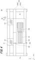
Fig. 4 is a diagram of the state around thehoist 100 including the hoistwaytop structure 30 as viewed from an upper surface (Z direction). -
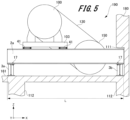
Fig. 5 is a front view of the state around thehoist 100 including the hoistwaytop structure 30 as viewed from a direction (Y direction) along the rotation axis of thehoist 100. -
Fig. 6 is an exploded perspective view of a main part of the hoistwaytop structure 30. -
Fig. 7 is a diagram of afirst machine beam 2a as viewed from a lower part in a lateral direction. -
Fig. 8 is a diagram of afirst spacer 3a as viewed from an upper part in the lateral direction. -
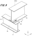
Fig. 9 is a perspective view of a main part when thefirst machine beam 2a is fixed to thefirst spacer 3a after an end part of thefirst machine beam 2a is cut. -
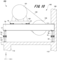
Fig. 10 is a schematic configuration diagram of a hoistwaytop structure 200 according to a second embodiment of the present invention. - Hereinafter, an example of a hoistway top structure of an elevator and a method for installing the hoistway top structure according to embodiments of the present invention will be described with reference to the drawings. Note that the present invention is not limited to the following examples. In the drawings described below, common members are denoted by the same reference numerals.
- First, an overall configuration of an elevator to which a hoistway top structure of the elevator according to a first embodiment of the present invention (hereinafter referred to as "the present embodiment") is applied will be described with reference to
Figs. 1 and2 .Fig. 1 is an overall configuration diagram of an elevator according to the present embodiment, andFig. 2 is a schematic configuration diagram when the elevator according to the present embodiment is viewed from a direction different from that inFig. 1 . - As illustrated in
Fig. 1 , anelevator 1 of the present embodiment is provided in ahoistway 110 formed in a building structure. Theelevator 1 moves up and down in thehoistway 110 and includes acar 120 on which a person and luggage are loaded, amain rope 130, acounterweight 170, and ahoist 100. Hereinafter, a direction in which thecar 120 moves up and down will be described as a vertical direction. - The
hoistway 110 is a space for thecar 120 to ascend and descend, and is provided penetrating each floor in a building in the vertical direction. A guide rail (not illustrated) that guides the ascent and descent of thecar 120 is attached to aninner wall surface 180 of thehoistway 110. Further, a landing door (not illustrated) leading to each floor is provided at a height position corresponding to each floor on thewall surface 180 of thehoistway 110. - Further, a
machine room 190 is provided at the top of thehoistway 110. Themachine room 190 is provided with a hoistwaytop structure 30 including a hoist support base 60 (seeFig. 2 ) to which thehoist 100 is fixed and a rope support mechanism 20 (seeFig. 2 ) that holds a tip of themain rope 130. The hoistwaytop structure 30 will be described in detail later. - The
car 120 is formed in a hollow substantially rectangular parallelepiped shape and is disposed in thehoistway 110. An on-car pulley 121 is provided at an upper end part of thecar 120, and themain rope 130 is wound around the on-car pulley 121. Thecar 120 is connected with thecounterweight 170 via themain rope 130 and moves up and down in thehoistway 110. Thiscar 120 is guided by a guide rail provided on thewall surface 180 in thehoistway 110, and moves up and down in the vertical direction in thehoistway 110. On a side surface of thecar 120, a car door (not illustrated) is provided at a position corresponding to the landing door of each floor, and when thecar 120 stops on each floor, the car door and the landing door are opened, so that a person and luggage are loaded onto and unloaded from thecar 120. - The
counterweight 170 is disposed in thehoistway 110, and a weight-side pulley 141 is provided at an upper end part. Themain rope 130 is wound around the weight-side pulley 141, and moves up and down in thehoistway 110 along a weight-side guide rail (not illustrated). Here, the on-car pulley 121 and the weight-side pulley 141 are arranged such that an axial direction thereof is orthogonal to asheave 101 and adeflector wheel 150 of the hoist 100. - It is fixed to the hoist
support base 60 provided in themachine room 190. As illustrated inFig. 2 , the hoist 100 includes thesheave 101 around which themain rope 130 is wound, adrive unit 102 that rotationally drives thesheave 101, and abase part 103 that supports thesheave 101 and thedrive unit 102. In addition, thedeflector wheel 150 on which themain rope 130 is mounted is provided in the vicinity of the hoist 100. The hoist 100 raises and lowers thecar 120 by winding up the woundmain rope 130. The hoist 100 is installed such that a rotation axis of thesheave 101 is orthogonal to an axial direction of rotation axes of the on-car pulley 121 and the weight-side pulley 141. - Both axial end parts of the
main rope 130 are fixed to therope support mechanism 20 provided in themachine room 190 at the top of thehoistway 110 via arope adjustment unit 131. Therope adjustment unit 131 is a member that adjusts tension of themain rope 130. Therope adjustment unit 131 will be described later in detail. After one end part of themain rope 130 is supported by the rope support mechanism in themachine room 190, in thehoistway 110, the main rope is wound around the on-car pulley 121, and then wound around thesheave 101 of the hoist 100 and thedeflector wheel 150. - Furthermore, after the
main rope 130 is wound around thesheave 101 of the hoist 100 and thedeflector wheel 150, the main rope is wound around the weight-side pulley 141. Then, another end part of themain rope 130 is fixed to therope support mechanism 20 provided in themachine room 190 at the top of thehoistway 110 via therope adjustment unit 131. When the hoist 100 is driven, thecar 120 and thecounterweight 170 move up and down in thehoistway 110 via themain rope 130. - Next, the hoistway
top structure 30 used in theelevator 1 of the present embodiment will be described.Fig. 3 is a front view of a state around the hoist 100 including the hoistwaytop structure 30 as viewed from a direction (X direction) orthogonal to a rotation axis of the hoist 100. Further,Fig. 4 is a diagram of the state around the hoist 100 including the hoistwaytop structure 30 as viewed from an upper surface (Z direction). Further,Fig. 5 is a front view of the state around the hoist 100 including the hoistwaytop structure 30 as viewed from a direction (Y direction) along the rotation axis of the hoist 100. - As illustrated in
Figs. 3 and4 , the hoistwaytop structure 30 includes afirst spacer 3a, asecond spacer 3b, afirst machine beam 2a, asecond machine beam 2b, arope end beam 2c, and a pair ofsupport plates floor surface 161 in themachine room 190. In the present embodiment, an example in which thefirst spacer 3a, thesecond spacer 3b, thefirst machine beam 2a, thesecond machine beam 2b, and therope end beam 2c are formed of a so-called H-shaped steel having an H-shaped cross-sectional shape will be described. The H-shaped steel includes a pair of rectangular flange parts extending in one direction and a connection part connecting the pair of flange parts. - In the following description, in the H-shaped steel, an extending direction thereof will be described as a longitudinal direction, and a direction orthogonal to the longitudinal direction and perpendicular to a pair of flange parts extending in the longitudinal direction will be described as a lateral direction. In addition, a direction orthogonal to the longitudinal direction and the lateral direction will be described as a width direction. In addition, when the
first machine beam 2a, thesecond machine beam 2b, and therope end beam 2c are not particularly distinguished, they are simply described as a supportingbeam 2. - The
first spacer 3a and thesecond spacer 3b are made of H-shaped steel having the same length in the lateral direction and the same length in the longitudinal direction. Further, thefirst machine beam 2a and thesecond machine beam 2b are also made of H-shaped steel having the same length in the lateral direction and the same length in the longitudinal direction. Therope end beam 2c is made of H-shaped steel having a length in the lateral direction shorter than those of thefirst machine beam 2a and thesecond machine beam 2b and a length in the longitudinal direction equal to those of thefirst machine beam 2a and thesecond machine beam 2b. - The
first spacer 3a and thesecond spacer 3b are arranged such that the longitudinal directions thereof are parallel to each other, and are arranged on thefloor surface 161 of themachine room 190 such that the longitudinal directions thereof are substantially parallel to an axial direction of thesheave 101 of the hoist 100. Further, thefirst spacer 3a and thesecond spacer 3b are placed at the top of abeam 112 of a building in the machine room 190 (seeFig. 5 ). - The
first spacer 3a and thesecond spacer 3b include alower flange part 11, anupper flange part 12 facing thelower flange part 11, and a connection part 13 (seeFig. 6 ) connecting thelower flange part 11 and theupper flange part 12. As illustrated inFig. 3 , thelower flange part 11 is fixed to thefloor surface 161 in themachine room 190 bybolts 45. - Further, as shown in
Fig. 6 , theupper flange part 12 is provided with elliptical spacer holes 50. Theelliptical spacer hole 50 is an elliptical hole elongated in the width direction. Then,bolts 17 for fixing thefirst machine beam 2a, thesecond machine beam 2b, and therope end beam 2c pass through the elliptical spacer holes 50 of thefirst spacer 3a and thesecond spacer 3b. Details of theelliptical spacer hole 50 will be described later. A height of the hoist 100 in the vertical direction from thefloor surface 161 of themachine room 190 is adjusted by thefirst spacer 3a and thesecond spacer 3b. - The
first machine beam 2a and thesecond machine beam 2b are arranged at the top of thefirst spacer 3a and thesecond spacer 3b such that longitudinal directions thereof are parallel to each other and orthogonal to the longitudinal directions of thefirst spacer 3a and thesecond spacer 3b. Thefirst machine beam 2a and thesecond machine beam 2b are arranged at a predetermined interval (an interval at which abase part 103 of the hoist 100 can be placed) in the longitudinal directions of thefirst spacer 3a and thesecond spacer 3b. - The
first machine beam 2a and thesecond machine beam 2b each include alower flange part 5, anupper flange part 6 facing thelower flange part 5, and aconnection part 7 connecting thelower flange part 5 and theupper flange part 6. Thelower flange part 5 is provided with a plurality of bolt holes used when fixing to thefirst spacer 3a and thesecond spacer 3b. Here, among the plurality of bolt holes provided in thefirst machine beam 2a and thesecond machine beam 2b, the bolt hole provided on one side in the longitudinal direction (in the present embodiment, a side fixed to thefirst spacer 3a) is an elliptical beam hole 40 (seeFig. 6 ). Theelliptical beam hole 40 corresponds to a beam hole of the present invention, and a configuration thereof will be described in detail later. - In the present embodiment, the
first machine beam 2a and thesecond machine beam 2b constitute the hoistsupport base 60 that supports the hoist 100. The hoist 100 is installed at the top of theupper flange parts 6 of thefirst machine beam 2a and thesecond machine beam 2b via vibration-proof members 41. Then, the hoist 100 is fixed to thefirst machine beam 2a and thesecond machine beam 2b by bolts. - Similarly to the
first machine beam 2a and thesecond machine beam 2b, therope end beam 2c is disposed at the top of thefirst spacer 3a and thesecond spacer 3b. Therope end beam 2c is disposed on a side opposite to thefirst machine beam 2a side with respect to thesecond machine beam 2b, and is disposed such that a longitudinal direction thereof is parallel to the longitudinal directions of thefirst machine beam 2a and thesecond machine beam 2b. A length in the longitudinal direction of therope end beam 2c is configured to be the same as the length in the longitudinal direction of thefirst machine beam 2a and thesecond machine beam 2b. On the other hand, a length in the lateral direction of therope end beam 2c is configured to be shorter than the length in the lateral direction of thefirst machine beam 2a and thesecond machine beam 2b. - The
rope end beam 2c includes alower flange part 15, anupper flange part 16 facing thelower flange part 15, and aconnection part 19 connecting thelower flange part 15 and theupper flange part 16. Thelower flange part 15 is provided with a plurality of bolt holes used when fixing to thefirst spacer 3a and thesecond spacer 3b. Here, among the plurality of bolt holes provided in therope end beam 2c, the bolt hole provided on at least one side in the longitudinal direction (in the present embodiment, a side fixed to thefirst spacer 3a) is the elliptical beam hole 40 (seeFig. 6 ). Theelliptical beam hole 40 has the same configuration as theelliptical beam hole 40 provided in thefirst machine beam 2a and thesecond machine beam 2b. Thiselliptical beam hole 40 will be described in detail later. - In addition, a pair of
support plates Fig. 3 ) of therope adjustment units 131 is disposed at the top of theupper flange part 16 of therope end beam 2c. - Each of the pair of
support plates support plate 21 is provided with a plurality of throughholes 135 through which thethimble rods 132 of therope adjustment units 131 described later pass. The pair ofsupport plates rope end beam 2c, and the throughholes 135 are arranged to be between thesecond machine beam 2b and therope end beam 2c. Each of the pair ofsupport plates upper flange part 16 of therope end beam 2c with a bolt (not illustrated). In the present embodiment, therope support mechanism 20 is configured by therope end beam 2c and the pair ofsupport plates - Here, the
rope adjustment unit 131 supported by thesupport plate 21 will be described. Therope adjustment unit 131 is provided at both axial end parts of themain rope 130. As illustrated inFig. 3 , therope adjustment unit 131 includes thethimble rod 132, aspring member 133, and anut 134. - The
thimble rod 132 is a rod-shaped member having an outer peripheral surface on which a male screw is formed, and is fixed to each of both axial end parts of themain rope 130. When themain rope 130 is supported by therope support mechanism 20, first, thisthimble rod 132 is passed through the throughhole 135 of thesupport plate 21 from a lower side in the vertical direction. Then, thespring member 133 is inserted into thethimble rod 132 passing through the throughhole 135 of thesupport plate 21, and thenut 134 is screwed from an end part of thethimble rod 132 so as to generate predetermined tension in thespring member 133 and fixed at a predetermined position. The tension of themain rope 130 can be adjusted by expansion and contraction of thespring member 133. - In the present embodiment, one end part of the
main rope 130 is supported by onesupport plate 21 via therope adjustment unit 131, and another end part of themain rope 130 is supported by anothersupport plate 21 via therope adjustment unit 131. - When the hoistway
top structure 30 is installed, in order to install thefirst spacer 3a and thesecond spacer 3b at the top of thebeam 112 of the building, as illustrated inFig. 5 , there is a case where thewall surface 180 of thehoistway 110 is dug to provide arecess 111. In this case, after therecess 111 is provided, thefirst spacer 3a and thesecond spacer 3b are disposed at the top of thebeam 112. Then, it is necessary to adjust arrangement positions of thefirst machine beam 2a, thesecond machine beam 2b, and therope end beam 2c with respect to arrangement positions of thefirst spacer 3a and thesecond spacer 3b. Even when therecess 111 is not provided, the arrangement positions of thefirst spacer 3a and thesecond spacer 3b and the arrangement positions of thefirst machine beam 2a, thesecond machine beam 2b, and therope end beam 2c with respect to those of thefirst spacer 3a and thesecond spacer 3b are adjusted on site in accordance with dimensions of the building. Therefore, when the hoistwaytop structure 30 is installed, a process of cutting thefirst machine beam 2a, thesecond machine beam 2b, and therope end beam 2c in accordance with the dimensions of the building may be required. -
Fig. 6 is an exploded perspective view of a main part of the hoistwaytop structure 30.Fig. 6 illustrates thefirst spacer 3a, and thefirst machine beam 2a, thesecond machine beam 2b, and therope end beam 2c fixed to theupper flange part 12 of thefirst spacer 3a. Hereinafter, thefirst machine beam 2a, thesecond machine beam 2b, and therope end beam 2c are collectively referred to as the supportingbeam 2. - In the present embodiment, among the bolt holes for fixing to the
first spacer 3a and thesecond spacer 3b in the supportingbeam 2, at least the bolt hole on the side fixed to thefirst spacer 3a (one side in the present invention) is configured by the plurality of elliptical beam holes 40. Furthermore, among thefirst spacer 3a and thesecond spacer 3b, the bolt hole of thefirst spacer 3a corresponding to theelliptical beam hole 40 of the supportingbeam 2 is formed of the elliptical spacer holes 50. As a result, even when an end part on one side of the supportingbeam 2 where the plurality of elliptical beam holes 40 is provided is cut for dimensional adjustment, theelliptical beam hole 40 that is not divided can be used for bolt fastening (seeFig. 9 ). - Note that, in the present embodiment, although not illustrated, in the supporting
beam 2, a bolt hole on another side to be fixed to thesecond spacer 3b and a bolt hole of thesecond spacer 3b provided at a position overlapping with the bolt hole are constituted by a round hole having a perfect circular shape used for normal bolt fastening. - Hereinafter, detailed configurations of the
elliptical beam hole 40 provided in the supportingbeam 2 and theelliptical spacer hole 50 provided in thefirst spacer 3a will be described. Note that, since the configurations of the elliptical beam holes 40 in thefirst machine beam 2a, thesecond machine beam 2b, and therope end beam 2c are the same, theelliptical beam hole 40 of thefirst machine beam 2a will be representatively described below. -
Fig. 7 is a diagram of thefirst machine beam 2a as viewed from a lower part in the lateral direction. Thelower flange part 5 of thefirst machine beam 2a has afirst flange piece 5a and asecond flange piece 5b. Thefirst flange piece 5a is formed so as to protrude to one side from theconnection part 7 provided at the center of thelower flange part 5 in the width direction. Thesecond flange piece 5b is formed to protrude from theconnection part 7 to another side. - As illustrated in
Fig. 7 , theelliptical beam hole 40 is provided on one side in a direction along the longitudinal direction of thefirst machine beam 2a, and is constituted by an elliptical hole elongated in the longitudinal direction of thefirst machine beam 2a. Further, theelliptical beam hole 40 is provided in thefirst flange piece 5a and thesecond flange piece 5b of thefirst machine beam 2a symmetrically with respect to theconnection part 7. Furthermore, the plurality of (two inFig. 7 ) elliptical beam holes 40 is provided at a predetermined distance W2 in the direction along the longitudinal direction of thefirst machine beam 2a. Here, the distance W2 between the plurality of elliptical beam holes 40 arranged in the direction along the longitudinal direction of thefirst machine beam 2a is secured to be equal to or longer than a distance necessary for strength. Further, a length W1 of theelliptical beam hole 40 in the longitudinal direction of thefirst machine beam 2a will be described later. -
Fig. 8 is a diagram of thefirst spacer 3a as viewed from an upper part in the lateral direction. Theupper flange part 12 of thefirst spacer 3a includes afirst flange piece 12a and asecond flange piece 12b. Thefirst flange piece 12a is formed to protrude from theconnection part 13 provided at the center of theupper flange part 12 in the width direction toward a side where the hoist 100 is installed. Thesecond flange piece 12b is formed to protrude to a side opposite to the side where the hoist 100 is installed. - The
elliptical spacer hole 50 is provided in thefirst flange piece 12a of theupper flange part 12 on the hoist 100 side, and is configured by an elliptical hole elongated in the width direction of theupper flange part 12. In addition, the plurality of elliptical spacer holes 50 is provided along the longitudinal direction of thefirst spacer 3a so as to correspond to the elliptical beam holes 40 provided in thefirst machine beam 2a, thesecond machine beam 2b, and therope end beam 2c arranged at the top. - Here, a length W3 of the
elliptical spacer hole 50 in the width direction of thefirst spacer 3a is configured to be equal to or more than W3 = 2W5 + W2, where W5 is a diameter of a bolt inserted when thefirst spacer 3a and the supportingbeam 2 are fixed. In addition, it suffices if the length W3 of theelliptical spacer hole 50 is smaller than a width of thefirst flange piece 12a in the width direction and is equal to or smaller than a width that can secure strength of thefirst flange piece 12a. - On the other hand, as illustrated in
Fig. 7 , the length W1 of theelliptical beam hole 40 in the longitudinal direction of thefirst machine beam 2a is configured to be longer than the diameter W5 of the bolt and smaller than W5 + W4. Here, as illustrated inFig. 8 , a length W4 is a distance from an end part of thefirst spacer 3a on another side opposite to one side where the supportingbeam 2 extends to an end part of theelliptical spacer hole 50 on another side. Further, the length W1 of theelliptical beam hole 40 is configured to be more preferably smaller than W5 + W4 - W2. - Note that a width of the
elliptical beam hole 40 in the width direction of thefirst machine beam 2a and a width of theelliptical spacer hole 50 in the longitudinal direction of thefirst spacer 3a are set to widths through which a bolt to be used can be inserted. -
Fig. 9 is a perspective view of a main part when the end part on one side of thefirst machine beam 2a is fixed to thefirst spacer 3a after the end part on one side of thefirst machine beam 2a is cut. In the present embodiment, in thefirst machine beam 2a, the plurality of elliptical beam holes 40 is provided at the end part on one side fixed to thefirst spacer 3a. As a result, even when theelliptical beam hole 40 on the end side is divided along with the cutting of thefirst machine beam 2a, it is possible to fasten thefirst spacer 3a with a bolt using the undividedelliptical beam hole 40 provided on the other side of the dividedelliptical beam hole 40. - Meanwhile, in a case where the bolt hole of the
first spacer 3a is configured by a round hole having a perfect circular shape, a situation in which the bolt hole of thefirst spacer 3a exists between the two adjacent elliptical beam holes 40 of the supportingbeam 2 occurs after adjustment of a fixing position of the supportingbeam 2. In this case, thefirst spacer 3a and the supportingbeam 2 cannot be bolted at appropriate positions. On the other hand, in the present embodiment, by setting the length W3 of theelliptical spacer hole 50 to 2W5 + W2 or more, it is possible to reliably fasten the supportingbeam 2 and thefirst spacer 3a with the bolt after adjusting the fixing position of the supportingbeam 2. - Further, in the present embodiment, by making the length W1 of the
elliptical beam hole 40 of the supportingbeam 2 smaller than W5 + W4, even when the supportingbeam 2 is cut, theelliptical beam hole 40 that is not divided can be used for bolt fastening. Furthermore, more preferably, by making the length W1 of theelliptical beam hole 40 smaller than W5 + W4 - W2, even when the supportingbeam 2 is cut, theelliptical beam hole 40 that is not divided can be used for bolt fastening while maintaining strength of the supportingbeam 2. - In the present embodiment, it is possible to fasten each supporting
beam 2 and thefirst spacer 3a with a bolt at any position as long as the position is within a range from the end part on one side in the longitudinal direction of each supportingbeam 2 to theelliptical beam hole 40 arranged on the most other side in the longitudinal direction. Therefore, the length of each supportingbeam 2 can flexibly correspond to a dimensional error caused by the arrangement positions of thefirst spacer 3a and thesecond spacer 3b. - Note that, in the
first machine beam 2a, in an initial state before cutting, a length W6 of an interval from an end part on thefirst spacer 3a side in the longitudinal direction to an end part on thefirst spacer 3a side of theelliptical beam hole 40 is preferably W4 + W5 - W5. As a result, when the supportingbeam 2 is not cut, the bolt fastening can be performed in a state where the end part on one side in the longitudinal direction of the supportingbeam 2 and the end part on one side in the width direction of thefirst spacer 3a are aligned in the vertical direction. - Next, an example of a method for installing the hoistway
top structure 30 of the present embodiment will be described. First, arrangement positions of thefirst spacer 3a and thesecond spacer 3b are determined in themachine room 190. For example, thefirst spacer 3a and thesecond spacer 3b are adjusted to be arranged at the top of thebeam 112 of the building, and if necessary, thewall surface 180 of thehoistway 110 is dug to form therecess 111. - Next, a length in the longitudinal direction of each supporting
beam 2 is determined. In this case, as illustrated inFig. 5 , a length L from an end part in the width direction of thefirst spacer 3a on a side opposite to thesecond spacer 3b side to an end part in the width direction of thesecond spacer 3b on a side opposite to thefirst spacer 3a side is the length in the longitudinal direction of each supportingbeam 2. Therefore, each supportingbeam 2 is cut so that the length of each supportingbeam 2 is the length L. For example, when a length in the longitudinal direction of thefirst machine beam 2a is adjusted, an end part on one side where the elliptical beam holes 40 are provided in the longitudinal direction of thefirst machine beam 2a is cut. Similarly, when a length in the longitudinal direction of thesecond machine beam 2b or therope end beam 2c is adjusted, an end part on one side where the elliptical beam holes 40 are provided in the longitudinal direction is cut. - Here, a cuttable dimension (adjustment allowance) of the supporting
beam 2 is a dimension from an end part on one side of the supportingbeam 2 to a position where theelliptical beam hole 40 provided on the most other side is not divided. As a result, at least theelliptical beam hole 40 provided on the most other side of the supportingbeam 2 can be maintained in an undivided state. For this reason, in the supportingbeam 2, the plurality of elliptical beam holes 40 is provided according to a necessary adjustment allowance in advance. - After each supporting
beam 2 is cut, each of the supportingbeams 2 is arranged on thefirst spacer 3a and thesecond spacer 3b to adjust a fixing position. At this time, each supportingbeam 2 is arranged such that the end part on one side where the elliptical beam holes 40 are provided overlaps the top of thefirst spacer 3a. - In the present embodiment, the length in the longitudinal direction of each supporting
beam 2 is set to the length L from the end part in the width direction of thefirst spacer 3a on the side opposite to thesecond spacer 3b side to the end part in the width direction of thesecond spacer 3b on the side opposite to thefirst spacer 3a side. Therefore, both end parts in the longitudinal direction of each supportingbeam 2 are arranged so as to be aligned in the vertical direction with the end parts in the width direction of thefirst spacer 3a and thesecond spacer 3b on the side opposite to the side on which the hoist 100 is provided. - As illustrated in
Fig. 9 , even when theelliptical beam hole 40 on the end side in the longitudinal direction is divided by cutting each supportingbeam 2, theelliptical beam hole 40 which is not divided overlaps theelliptical spacer hole 50 in a state where a position where the elliptical spacer hole can be bolted is maintained. At this position, thebolt 17 is passed through theelliptical spacer hole 50 provided in thefirst spacer 3a and theelliptical beam hole 40 located at the top of the elliptical spacer hole via awasher 18, and a lower portion of thebolt 17 is fastened with a nut (not illustrated). As a result, each supportingbeam 2 can be fixed to thefirst spacer 3a. - On the other hand, since the end part in the longitudinal direction of each supporting
beam 2 on the side opposite to the side on which the elliptical beam holes 40 are provided is not cut in the present embodiment, a relative positional relationship with thesecond spacer 3b does not change from a design stage. Therefore, for the bolt hole of each supportingbeam 2 for fixing to thesecond spacer 3b and the bolt hole of thesecond spacer 3b for fixing to each supportingbeam 2, a generally applied perfect circular bolt hole (round hole) can be used. Therefore, on thesecond spacer 3b side, it is possible to fasten each supportingbeam 2 with a bolt using the perfect circular bolt hole. - Incidentally, even when only one
elliptical beam hole 40 is formed in each supportingbeam 2 in the longitudinal direction of the supportingbeam 2, the fixing position between each supportingbeam 2 and thefirst spacer 3a can be adjusted according to the length of theelliptical beam hole 40. However, in this case, when the supportingbeam 2 is cut in accordance with the length L determined by the arrangement positions of thefirst spacer 3a and thesecond spacer 3b, theelliptical beam hole 40 may also be divided. Even if the supportingbeam 2 can be bolted to thefirst spacer 3a using the dividedelliptical beam hole 40, when the hoistsupport base 60 is displaced in a horizontal direction due to an earthquake or the like, an end part of theelliptical beam hole 40 cannot receive the displacement of the bolt in a shearing direction. Then, there is a problem that the hoist 100 falls. - On the other hand, in the present embodiment, the plurality of elliptical beam holes 40 for bolting each supporting
beam 2 to thefirst spacer 3a is provided in the longitudinal direction. Therefore, after the fixing positions of each supportingbeam 2 and thefirst spacers 3a are adjusted, bolt fastening can be performed using theelliptical beam hole 40 that is not divided. Therefore, even when a horizontal force is generated in thefirst machine beam 2a, thesecond machine beam 2b, and therope end beam 2c due to an earthquake or the like, the bolt abuts on the end part of theelliptical beam hole 40. As a result, it is possible to stop the displacement of thefirst machine beam 2a, thesecond machine beam 2b, and therope end beam 2c. - In the present embodiment, an example has been described in which the bolt hole formed in the
first spacer 3a is an elliptical hole (elliptical spacer hole 50), and the bolt hole provided on the side of each supportingbeam 2 fixed to thefirst spacer 3a is an elliptical hole (elliptical beam hole 40). However, the present invention is not limited thereto. For example, theelliptical spacer hole 50 of the present embodiment may be provided in thesecond spacer 3b, and theelliptical beam hole 40 of the present embodiment may be provided at the end part on the other side fixed to thesecond spacer 3b in the longitudinal direction of each supportingbeam 2. Also in this case, when the length in the longitudinal direction of each supportingbeam 2 is adjusted, it suffices if the end part on the other side where the elliptical beam holes 40 are provided is cut. - Furthermore, the
first spacer 3a and thesecond spacer 3b may be provided with the elliptical spacer holes 50 of the present embodiment, and the plurality of elliptical beam holes 40 of the present embodiment may be provided at both end parts in the longitudinal direction of each supportingbeam 2. In this case, since both end parts in the longitudinal direction of each supportingbeam 2 can be cut for length adjustment, a larger adjustment allowance can be secured as compared with the present embodiment. - Next, a hoistway
top structure 200 according to a second embodiment of the present invention will be described.Fig. 10 is a schematic configuration diagram of the hoistwaytop structure 200 according to the second embodiment. InFig. 10 , portions corresponding to those inFig. 5 are denoted by the same reference numerals, and redundant description is omitted. - In the hoistway
top structure 200 according to the second embodiment, thefirst spacer 3a is fixed to the top of a firstauxiliary spacer 3c via a spacer vibration-proof member 51, and thesecond spacer 3b is fixed to the top of a secondauxiliary spacer 3d via the spacer vibration-proof member 51. - The first
auxiliary spacer 3c and the secondauxiliary spacer 3d are made of the same H-shaped steel as thefirst spacer 3a and thesecond spacer 3b, respectively. Further, lengths in the longitudinal direction, the lateral direction, and the width direction of the firstauxiliary spacer 3c and the secondauxiliary spacer 3d are equal to the lengths of thefirst spacer 3a and thesecond spacer 3b, respectively. - Each of the first
auxiliary spacer 3c and the secondauxiliary spacer 3d is fixed to a floor surface in themachine room 190 by a bolt (not illustrated), and the spacer vibration-proof member 51 is fixed to the top in the vertical direction by a bolt. Further, thefirst spacer 3a and thesecond spacer 3b are fixed by bolts to the top in the vertical direction of the spacer vibration-proof member 51 fixed to the top in the vertical direction of the firstauxiliary spacer 3c and the secondauxiliary spacer 3d, respectively. - In the present embodiment, the
first spacer 3a and thesecond spacer 3b are fixed to the top of the firstauxiliary spacer 3c and the secondauxiliary spacer 3d, respectively, with the spacer vibration-proof member 51 interposed therebetween. Therefore, vibration transmitted to each supportingbeam 2 and vibration related to the hoist 100 can be reduced. In addition, since the configuration is similar to that of the first embodiment, similar effects can be obtained. - Incidentally, in the first embodiment and the second embodiment, the
first spacer 3a and thesecond spacer 3b are formed of members extending from thefirst machine beam 2a to therope end beam 2c in the width direction of each supportingbeam 2. However, a pair of spacers may be provided for each supportingbeam 2. That is, in this case, a total of six spacers are arranged in order to arrange thefirst machine beam 2a, thesecond machine beam 2b, and therope end beam 2c. - Even in a case where the pair of spacers is provided for each supporting
beam 2, the plurality of elliptical beam holes 40 illustrated inFig. 7 is provided at an end part on a cut side in the longitudinal direction of each supportingbeam 2. Further, theelliptical spacer hole 50 illustrated inFig. 8 is provided in one of the pair of spacers to which the end part on the cut side in the longitudinal direction of each supportingbeam 2 is fixed. As a result, effects similar to those of the first embodiment can be obtained. - Further, in the embodiments described above, the
first spacer 3a, thesecond spacer 3b, and each supportingbeam 2 are formed of the H-shaped steel having the H-shaped cross section, but the present invention is not limited thereto. For example, it may be configured by a member having a U-shaped cross section including a pair of rectangular flange parts extending in one direction and a connection part connecting the pair of flange parts at end parts in the width direction orthogonal to the longitudinal direction of the pair of flange parts. In addition, various shapes can be applied. - Further, in the above-described embodiments, the beam hole in the present invention is configured by the elliptical beam hole elongated in the direction along the longitudinal direction of the supporting beam, but the present invention is not limited thereto. The bolt hole (beam hole) provided on the supporting beam side may be configured by a normal perfect circle, and even in this case, the same effects as those of the above-described embodiments can be obtained.
- The above-described embodiments have been described in detail in order to describe the present invention in an easy-to-understand manner, and are not necessarily limited to those having all the described configurations. For example, a part of the configuration of the embodiment can be replaced with another configuration, and another configuration can be added to the configuration of the embodiment. In addition, it is possible to add, delete, and replace another configuration for a part of the configuration of the embodiment.
-
- 1
- elevator
- 2
- supporting beam
- 2a
- first machine beam
- 2b
- second machine beam
- 2c
- rope end beam
- 3a
- first spacer
- 3b
- second spacer
- 5
- lower flange part
- 5a
- first flange piece
- 5b
- second flange piece
- 6
- upper flange part
- 7
- connection part
- 11
- lower flange part
- 12
- upper flange part
- 12a
- first flange piece
- 12b
- second flange piece
- 13
- connection part
- 15
- lower flange part
- 16
- upper flange part
- 17
- bolt
- 18
- washer
- 20
- rope support mechanism
- 21
- support plate
- 30
- hoistway top structure
- 40
- elliptical beam hole
- 41
- vibration-proof member
- 45
- bolt
- 50
- elliptical spacer hole
- 51
- spacer vibration-proof member
- 60
- hoist support base
- 100
- hoist
- 101
- sheave
- 102
- drive unit
- 103
- base part
- 110
- hoistway
- 111
- recess
- 112
- beam
- 121
- on-car pulley
- 130
- main rope
- 131
- rope adjustment unit
- 132
- thimble rod
- 133
- spring member
- 134
- nut
- 135
- through hole
- 141
- weight-side pulley
- 161
- floor surface
- 180
- inner wall surface
- 190
- machine room
- 200
- hoistway top structure
Claims (10)
- A hoistway top structure comprising:at least a pair of spacers disposed on a floor surface of a machine room at a hoistway top; anda supporting beam disposed such that both end parts in a longitudinal direction are fixed to respective tops of the pair of spacers, whereinan elliptical spacer hole, which is longer in a direction along the longitudinal direction of the supporting beam, is provided on an upper surface of at least one spacer of the pair of spacers at the supporting beam side,in the supporting beam, a plurality of beam holes is provided along the longitudinal direction of the supporting beam at an end part on a side disposed on the top of the at least one spacer, andthe one spacer and the end part in the longitudinal direction of the supporting beam arranged at the top of the one spacer are fixed with a bolt that passes through the elliptical spacer hole and the beam hole provided at an upper position overlapping the elliptical spacer hole.
- The hoistway top structure according to claim 1, wherein
the beam hole is configured by an elliptical hole elongated in the direction along the longitudinal direction of the supporting beam. - The hoistway top structure according to claim 1, wherein
a length of the elliptical spacer hole in the longitudinal direction of the supporting beam is set to be larger than 2Ws + W2, where W5 is a diameter of the bolt, and W2 is a distance between the adjacent beam holes provided in the longitudinal direction of the supporting beam. - The hoistway top structure according to any one of claims 1 to 3, wherein
a length of the beam hole in the longitudinal direction of the supporting beam is set to be smaller than W5 + W4, where W5 is a diameter of the bolt, and W4 is a distance from an end part on another side opposite to one side where the supporting beam extends to an end part of the elliptical spacer hole on another side of the one spacer in the direction along the longitudinal direction of the supporting beam. - The hoistway top structure according to any one of claims 1 to 3, wherein
a length of the beam hole in the longitudinal direction of the supporting beam is set to be smaller than W5 + W4 - W2, where W5 is a diameter of the bolt, W2 is a distance between the adjacent beam holes provided in the longitudinal direction of the supporting beam, and W4 is a distance from an end part on another side opposite to one side where the supporting beam extends to an end part of the elliptical spacer hole on another side. - The hoistway top structure according to claim 1, wherein
the supporting beam constitutes a hoist support base that supports a hoist. - The hoistway top structure according to claim 1, whereinthe plurality of the supporting beams is arranged in parallel in the longitudinal direction of the supporting beam, andthe plurality of supporting beams constitutes a hoist support base that supports a hoist and a rope support mechanism that supports end parts of a main rope wound around the hoist.
- A method for installing a hoistway top structure, comprising:preparing a supporting beam in which a plurality of beam holes is provided at an end part on at least one side in a longitudinal direction;preparing a pair of spacers in which an elliptical spacer hole, which is longer in a direction along the longitudinal direction of the supporting beam, is provided on an upper surface at the supporting beam side of at least one spacer of the pair of spacers;arranging the pair of spacers at predetermined positions on a floor surface at a hoistway top;adjusting an arrangement position of the supporting beam according to an interval between the pair of spacers, arranging an end part on one side where the beam holes of the supporting beam are provided at a top of the one spacer where the elliptical spacer hole is provided, and arranging an end part on another side of the supporting beam at a top of another spacer; andinserting a bolt into the elliptical spacer hole and the beam hole and fixing with a nut.
- The method for installing the hoistway top structure according to claim 8, whereinin the adjustment of the arrangement position of the supporting beam, the end part of the supporting beam on the side where the beam holes are provided is cut according to the interval between the pair of spacers, anda position of the cutting is a position closer to one side than a beam hole provided on a most other side from the end part on one side of the supporting beam.
- An elevator comprising: a hoistway top structure, includingat least a pair of spacers disposed on a floor surface of a machine room at a hoistway top, anda supporting beam disposed such that both end parts in a longitudinal direction are fixed to respective tops of the pair of spacers, whereinan elliptical spacer hole, which is longer in a direction along the longitudinal direction of the supporting beam, is provided on an upper surface of at least one spacer of the pair of spacers at the supporting beam side,in the supporting beam, a plurality of beam holes is provided along the longitudinal direction at an end part on a side disposed on the top of the at least one spacer, andthe one spacer and the end part in the longitudinal direction of the supporting beam arranged at the top of the one spacer are fixed with a bolt that passes through the elliptical spacer hole and the beam hole provided at an upper position overlapping the elliptical spacer hole.
Applications Claiming Priority (1)
| Application Number | Priority Date | Filing Date | Title |
|---|---|---|---|
| PCT/JP2021/031111 WO2023026386A1 (en) | 2021-08-25 | 2021-08-25 | Hoistway top structure, method for installing hoistway top structure, and elevator |
Publications (2)
| Publication Number | Publication Date |
|---|---|
| EP4393862A1 true EP4393862A1 (en) | 2024-07-03 |
| EP4393862A4 EP4393862A4 (en) | 2025-06-25 |
Family
ID=85321791
Family Applications (1)
| Application Number | Title | Priority Date | Filing Date |
|---|---|---|---|
| EP21955000.1A Withdrawn EP4393862A4 (en) | 2021-08-25 | 2021-08-25 | Hoistway top structure, method for installing hoistway top structure, and elevator |
Country Status (4)
| Country | Link |
|---|---|
| EP (1) | EP4393862A4 (en) |
| JP (1) | JP7559251B2 (en) |
| CN (1) | CN117836230A (en) |
| WO (1) | WO2023026386A1 (en) |
Family Cites Families (8)
| Publication number | Priority date | Publication date | Assignee | Title |
|---|---|---|---|---|
| JPS60228386A (en) * | 1984-04-26 | 1985-11-13 | 三菱電機株式会社 | Vibrationproof device for elevator |
| JPH06115861A (en) * | 1992-10-06 | 1994-04-26 | Toshiba Corp | Elevator hoist |
| FI117336B (en) * | 2004-07-27 | 2006-09-15 | Kone Corp | Machinery underlay for an elevator |
| JP2008001509A (en) | 2006-06-26 | 2008-01-10 | Mitsubishi Electric Building Techno Service Co Ltd | Structure for elevator machine room on roof |
| FI125069B (en) * | 2009-10-28 | 2015-05-29 | Kone Corp | Fastening device for the lifting machinery of a lift and method for mounting the lifting machinery of a lift |
| JP5847239B2 (en) | 2014-06-05 | 2016-01-20 | 東芝エレベータ株式会社 | Elevator hoist installation method and apparatus |
| CN106794966B (en) | 2014-08-25 | 2019-04-12 | 三菱电机株式会社 | Traction machine installation device for elevators |
| CN205652987U (en) | 2016-06-01 | 2016-10-19 | 西继迅达(许昌)电梯有限公司 | Rope clamping device fixing device |
-
2021
- 2021-08-25 CN CN202180101628.9A patent/CN117836230A/en active Pending
- 2021-08-25 WO PCT/JP2021/031111 patent/WO2023026386A1/en not_active Ceased
- 2021-08-25 EP EP21955000.1A patent/EP4393862A4/en not_active Withdrawn
- 2021-08-25 JP JP2023543542A patent/JP7559251B2/en active Active
Also Published As
| Publication number | Publication date |
|---|---|
| CN117836230A (en) | 2024-04-05 |
| JPWO2023026386A1 (en) | 2023-03-02 |
| JP7559251B2 (en) | 2024-10-01 |
| WO2023026386A1 (en) | 2023-03-02 |
| EP4393862A4 (en) | 2025-06-25 |
Similar Documents
| Publication | Publication Date | Title |
|---|---|---|
| EP3960677A1 (en) | Modular elevator assembly and guide rail | |
| KR101687467B1 (en) | Traction machine base of elevator and elevator device | |
| US6422352B1 (en) | Procedure and apparatus for the installation of an elevator | |
| JP2004277175A (en) | Elevator counterweight | |
| JP7842028B2 (en) | Universal bracket for elevator rail systems | |
| KR100394505B1 (en) | Elevator unit | |
| EP4393862A1 (en) | Hoistway top structure, method for installing hoistway top structure, and elevator | |
| CN117255766A (en) | Methods for constructing elevators and such elevators | |
| JP2009220893A (en) | Car frame of elevator | |
| WO2021250776A1 (en) | Elevator guide rail fixing device and elevator device | |
| KR102422312B1 (en) | Installation structure of elevator traction machine | |
| JP7593767B2 (en) | Elevator hoisting machine and method for installing an elevator hoisting machine | |
| JP7391237B2 (en) | Construction method and equipment for elevator guide rails | |
| KR20190131440A (en) | Elevator car frame assembly | |
| JP2005132597A (en) | Elevator guide rail fixing device | |
| JP7230238B2 (en) | Elevator guide rail fixing device and elevator device | |
| JP2019210123A (en) | Elevator landing device and installation method thereof | |
| KR20180101486A (en) | Elevator device | |
| JP7449218B2 (en) | Guide rail and elevator | |
| KR102667968B1 (en) | Bracket for fixing the guide rail of the elevator | |
| CN223104698U (en) | Concrete operating platform and wind turbine tower | |
| JP7437532B2 (en) | Guide rail support structure and elevator | |
| JP2001026386A (en) | Elevator counterweight and centering method of counterweight | |
| RU2588411C2 (en) | Suspension and traction connecting device for elevators | |
| JP2024075305A (en) | Guide rail height adjustment device for elevator equipment, guide rail centering method, and guide rail installation method |
Legal Events
| Date | Code | Title | Description |
|---|---|---|---|
| STAA | Information on the status of an ep patent application or granted ep patent |
Free format text: STATUS: THE INTERNATIONAL PUBLICATION HAS BEEN MADE |
|
| PUAI | Public reference made under article 153(3) epc to a published international application that has entered the european phase |
Free format text: ORIGINAL CODE: 0009012 |
|
| STAA | Information on the status of an ep patent application or granted ep patent |
Free format text: STATUS: REQUEST FOR EXAMINATION WAS MADE |
|
| 17P | Request for examination filed |
Effective date: 20240325 |
|
| AK | Designated contracting states |
Kind code of ref document: A1 Designated state(s): AL AT BE BG CH CY CZ DE DK EE ES FI FR GB GR HR HU IE IS IT LI LT LU LV MC MK MT NL NO PL PT RO RS SE SI SK SM TR |
|
| DAV | Request for validation of the european patent (deleted) | ||
| DAX | Request for extension of the european patent (deleted) | ||
| STAA | Information on the status of an ep patent application or granted ep patent |
Free format text: STATUS: THE APPLICATION HAS BEEN WITHDRAWN |
|
| A4 | Supplementary search report drawn up and despatched |
Effective date: 20250528 |
|
| RIC1 | Information provided on ipc code assigned before grant |
Ipc: B66B 19/00 20060101ALI20250522BHEP Ipc: B66B 11/04 20060101AFI20250522BHEP |
|
| 18W | Application withdrawn |
Effective date: 20250617 |