EP4393856A1 - Transport device, specimen analysis system comprising transport device, and specimen pre-treatment device comprising transport device - Google Patents
Transport device, specimen analysis system comprising transport device, and specimen pre-treatment device comprising transport device Download PDFInfo
- Publication number
- EP4393856A1 EP4393856A1 EP22861068.9A EP22861068A EP4393856A1 EP 4393856 A1 EP4393856 A1 EP 4393856A1 EP 22861068 A EP22861068 A EP 22861068A EP 4393856 A1 EP4393856 A1 EP 4393856A1
- Authority
- EP
- European Patent Office
- Prior art keywords
- teeth
- specimen
- conveyance
- conveyance device
- yoke
- Prior art date
- Legal status (The legal status is an assumption and is not a legal conclusion. Google has not performed a legal analysis and makes no representation as to the accuracy of the status listed.)
- Pending
Links
Images



Classifications
-
- B—PERFORMING OPERATIONS; TRANSPORTING
- B65—CONVEYING; PACKING; STORING; HANDLING THIN OR FILAMENTARY MATERIAL
- B65G—TRANSPORT OR STORAGE DEVICES, e.g. CONVEYORS FOR LOADING OR TIPPING, SHOP CONVEYOR SYSTEMS OR PNEUMATIC TUBE CONVEYORS
- B65G54/00—Non-mechanical conveyors not otherwise provided for
- B65G54/02—Non-mechanical conveyors not otherwise provided for electrostatic, electric, or magnetic
-
- G—PHYSICS
- G01—MEASURING; TESTING
- G01N—INVESTIGATING OR ANALYSING MATERIALS BY DETERMINING THEIR CHEMICAL OR PHYSICAL PROPERTIES
- G01N35/00—Automatic analysis not limited to methods or materials provided for in any single one of groups G01N1/00 - G01N33/00; Handling materials therefor
- G01N35/02—Automatic analysis not limited to methods or materials provided for in any single one of groups G01N1/00 - G01N33/00; Handling materials therefor using a plurality of sample containers moved by a conveyor system past one or more treatment or analysis stations
- G01N35/04—Details of the conveyor system
-
- H—ELECTRICITY
- H02—GENERATION; CONVERSION OR DISTRIBUTION OF ELECTRIC POWER
- H02K—DYNAMO-ELECTRIC MACHINES
- H02K41/00—Propulsion systems in which a rigid body is moved along a path due to dynamo-electric interaction between the body and a magnetic field travelling along the path
- H02K41/02—Linear motors; Sectional motors
- H02K41/03—Synchronous motors; Motors moving step by step; Reluctance motors
- H02K41/031—Synchronous motors; Motors moving step by step; Reluctance motors of the permanent magnet type
-
- G—PHYSICS
- G01—MEASURING; TESTING
- G01N—INVESTIGATING OR ANALYSING MATERIALS BY DETERMINING THEIR CHEMICAL OR PHYSICAL PROPERTIES
- G01N35/00—Automatic analysis not limited to methods or materials provided for in any single one of groups G01N1/00 - G01N33/00; Handling materials therefor
- G01N35/02—Automatic analysis not limited to methods or materials provided for in any single one of groups G01N1/00 - G01N33/00; Handling materials therefor using a plurality of sample containers moved by a conveyor system past one or more treatment or analysis stations
- G01N35/04—Details of the conveyor system
- G01N2035/0474—Details of actuating means for conveyors or pipettes
- G01N2035/0477—Magnetic
-
- H—ELECTRICITY
- H02—GENERATION; CONVERSION OR DISTRIBUTION OF ELECTRIC POWER
- H02K—DYNAMO-ELECTRIC MACHINES
- H02K2201/00—Specific aspects not provided for in the other groups of this subclass relating to the magnetic circuits
- H02K2201/18—Machines moving with multiple degrees of freedom
Definitions
- Patent Document 1 describes a conveyance device that includes a conveyance target object having a permanent magnet, a magnetic pole having a core and a winding wound around an outer circumference of the core, a drive circuit applying a voltage to the winding, a current detection section detecting a value of a current flowing through the winding, and a calculation section calculating a position of the permanent magnet on the basis of a current value detected by the current detection section.
- a specimen analysis system for clinical examination performs tests of specified analysis items on specimens such as blood, plasma, serum, urine, and other body fluids.
- the specimen analysis system is able to connect devices having multiple functions and automatically performs individual processes. More specifically, in order to streamline laboratory operations, the specimen analysis system uses conveyance lines to connect analysis sections for multiple analytical fields such as biochemistry and immunology and a pretreatment section performing pretreatment necessary for analysis, and operates the connected sections as a single system.
- the conveyance lines used in a conventional specimen analysis system mainly adopt a belt-drive method.
- the belt-drive method has a problem in that, if conveyance is halted due to a certain abnormality, the specimens cannot be supplied to downstream devices. Therefore, it has been necessary to pay sufficient attention to belt wear.
- the system in Patent Document 1 described above estimates a position of the permanent magnet by detecting an inductance of a winding that varies with the position of the permanent magnet. Further, on the basis of the estimated position, the system controls the voltage applied to each winding so as to generate a thrust force in the permanent magnet.
- this method is used for a conveyance device having a plurality of windings arranged vertically and horizontally, the inductance of each winding varies depending on whether the winding is at the center, at the vertical ends, or at the horizontal ends. Therefore, the accuracy of estimating the position of the permanent magnet varies with the location. Further, it has been necessary to set characteristics for estimating the position of the permanent magnet for each location. Furthermore, since the inductance of the windings varies with the location, the current-thrust force characteristics (an amount of current required to obtain a constant thrust force) vary from one location to another. This problematically results in thrust force variations and complicated thrust force control, for example.
- the present invention includes a plurality of means for solving the above-mentioned problems.
- One example thereof is a conveyance device conveying a conveyance target object having a magnetic material.
- the conveyance device includes a plurality of teeth formed by a magnetic material, a plurality of windings wound around each of the plurality of teeth, a yoke in a shape of a lattice formed by a magnetic material magnetically connected to the plurality of teeth in order to support the plurality of teeth, and an additional yoke formed by a magnetic material magnetically connected to an outer end of the yoke.
- the conveyance device when the conveyance device includes the additional yoke formed by a magnetic material magnetically connected to the outer end of the yoke, it is possible to suppress a phenomenon in which the inductance of the windings varies with the location. This makes it possible to reduce a degree to which a magnitude of the thrust force depends on the location of the conveyance target object at a time of conveyance and stop of the conveyance target object. Further, it is possible to provide the conveyance device in which a detected value and a change value of current necessary for detecting the location of the conveyance target object are stable. That is, it is possible to realize the conveyance device that has high controllability of the conveyance target object and estimates the location of the conveyance target object with high accuracy. Problems, configurations, and advantages other than those described above will be apparent from the following description of embodiments.
- Part (b) of FIG. 2 is a diagram illustrating the yoke 40 that is extracted from the magnetic circuit section 2.
- the yoke 40 is shaped like a lattice and formed in correspondence with the three conveyance lines formed along the X-direction and with the three conveyance lines formed along the Y-direction.
- the yoke 40 is formed by a magnetic material and magnetically coupled to the plurality of teeth 20.
- the yoke 40 supports the plurality of teeth 20 such that the plurality of teeth 20 extend in the Z-direction.
- the teeth 20 include the teeth 20a which are each adjacent to one tooth, the teeth 20b which are each adjacent to two teeth, and the teeth 20c which are each adjacent to four teeth.
- the teeth 20a are disposed on the outermost side.
- the teeth 20a are adjacent to a tooth on only one side in the X-direction or the Y-direction.
- the teeth 20b are adjacent to teeth on both sides in the X-direction or the Y-direction.
- the teeth 20c are adjacent to teeth on both sides in the-X direction and on both sides in the Y-direction.
- the above-described teeth 20a, 20b, and 20c have different characteristics in terms of magnetic circuits.
- the inductance characteristics of the teeth vary with the number of adjacent teeth.
- the teeth 20a on the outer side have fewer adjacent teeth than the teeth 20b and 20c on the inner side. Therefore, the amount of magnetic flux generated when a constant current is passed through the winding 30 is smaller in the case of the teeth 20a on the outer side than those in the case of the teeth 20b and 20c on the inner side. Consequently, the thrust force acting on the conveyance target object 10 is relatively small in the case of the teeth 20a.
- Part (a) of FIG. 3 is a perspective view illustrating the magnetic circuit section of the conveyance device according to the first embodiment.
- Part (b) of FIG. 3 is a perspective view illustrating an additional yoke of the conveyance device according to the first embodiment.
- the teeth 20a on the outer side of the magnetic circuit section 2 have a small number of adjacent teeth, so that magnetic properties deteriorate. Therefore, the magnetic properties of the teeth 20a on the outer side can be improved by installing the additional yoke 45 formed by a magnetic material on the outer periphery of the yoke 40.
- the additional yoke 45 is connected to the outer periphery of the yoke 40.
- the magnetic properties of the disposed plurality of magnetic circuit sections 2 can easily be adjusted by installing the additional yoke 45 or changing the size of the additional yoke 45 after the plurality of magnetic circuit sections 2 are installed. Since operations performed outside the magnetic circuit section 2 are easier than operations performed inside the magnetic circuit section 2, it is easy to adjust the magnetic properties with the additional yoke 45. Further, the magnetic properties of the magnetic circuit section 2 can be changed by replacing the additional yoke 45 with an additional yoke of different dimensions. As a result, in a case where the mass or the subject of the conveyance target object 10 is changed, the magnetic properties of the magnetic circuit section 2 can easily be changed according to the conveyance target object 10.
- additional yoke 46 shaped like the letter L is coupled to a corner of the magnetic circuit section 2.
- additional yoke 47 shaped like a cross is coupled to the center of the magnetic circuit section 2.
- auxiliary teeth 21 are disposed between the teeth 20a on the outer side, it is possible to install a return path for the magnetic flux on the side (Z-direction) toward the conveyance surface (see FIG. 1 ) of a tooth. This can further improve the magnetic properties.
- FIG. 7 illustrates a modification of the fourth embodiment.
- the conveyance device according to the modification illustrated in FIG. 7 includes auxiliary teeth 21a and 21b that are formed by a magnetic material with no winding.
- the auxiliary teeth 21a are magnetically connected to the additional yoke 45 shaped like the letter T, and the auxiliary teeth 21b are magnetically connected to the additional yoke 46 shaped like the letter L.
- the auxiliary teeth 21a are disposed between the teeth 20a on the outer side.
- the auxiliary teeth 21b are disposed on a corner of the magnetic circuit section 2.
- a plurality of the auxiliary teeth 21a and 21b are disposed along the four sides of a substantially quadrilateral and become thicker and/or longer from the center of one side toward the corner. That is, the diameter of the auxiliary teeth 21b installed on the corners of the magnetic circuit section 2 is larger than that of the auxiliary teeth 21a. Further, the length of the auxiliary teeth 21b in the Z-direction is greater than that of the auxiliary teeth 21
- FIG. 8 is a perspective view illustrating a cross-section of the magnetic circuit section of the conveyance device according to the fifth embodiment.
- the magnetic circuit section 2 is partly cut away such that the teeth 20a on the outer side and the cross-sections of the teeth 20b and 20c on the inner side are visible.
- the teeth 20a on the outer side of the magnetic circuit section 2 and the teeth 20b and 20c on the inner side are coupled together through the yoke 40.
- the conveyance target object 10 includes a permanent magnet 11 and a holder cover 12.
- a force for drawing the conveyance target object 10 toward the winding 30 is generated to generate a force (thrust force) in the conveyance direction. That is, a force in the conveyance direction can efficiently be applied to the conveyance target object 10 by applying a voltage to a desired winding 30. Further, the orientation (direction) of the force to be applied in the conveyance direction can be controlled by selecting the winding 30 to which the voltage is to be applied.
- an inductance L can be calculated by detection of the current flowing through the winding 30 and the way the current flows. More specifically, upon detection of the inductance L of the winding 30 which varies with the location of the permanent magnet 11, the location of the permanent magnet 11 affecting the inductance L can be determined. Therefore, the drive circuit 50 is connected to the winding 30, and the current detection section 55 (e.g., a resistor) for detecting the value of the current flowing through the winding 30 is provided. Subsequently, a voltage is applied to the winding 30 by the drive circuit 50, then a current value generated by the applied voltage is detected by the current detection section 55, and the detected current value is read by the calculation section 53.
- the current detection section 55 e.g., a resistor
- the buffer 104 holds a plurality of specimen racks 111 conveyed by the conveyance line 102, in such a manner that the order of dispensing the specimens in the specimen racks 111 can be changed.
- the analysis section 105 analyzes the specimens that are conveyed from the buffer 104 through a conveyor line 106.
- the storage section 103 holds the specimen racks 111 that accommodate the specimen containers 122 containing the specimens that have been analyzed in the analysis section 105.
- the conveyance line 102 is a line for conveying the specimen racks 111 installed in the loading section 101, and has a configuration equivalent to that of any one of the conveyance devices according to the first to fifth embodiments which have been described above.
- the permanent magnet 11 is disposed on the back side of the specimen rack 111. That is, the specimen rack 111 acts as the conveyance target object 10.
- the reagent tray 114 is a member on which a reagent is placed when the reagent is to be registered in the specimen analysis system 100.
- the reagent ID reader 115 is an apparatus for acquiring reagent information by reading a reagent ID assigned to the reagent placed on the reagent tray 114.
- the reagent loader 116 is an apparatus that loads the reagent into the reagent disk 110.
- the specimen rack 111 is transferred by the conveyor line 106 to a specimen separation position near the reaction disk 108.
- the specimen dispensing nozzle 107 separates the specimen from the specimen containers 122 on the specimen rack 111 and dispenses the specimen into the reaction container of the reaction disk 108.
- the specimen dispensing nozzle 107 performs separation of the specimen as many times as necessary according to requested analysis items for the specimen.
- the specimen dispensing nozzle 107 separates the specimen from all the specimen containers 122 mounted on the specimen rack 111.
- the specimen rack 111 is transferred to the buffer 104. Further, upon completion of all specimen separation processes including an automatic re-examination, the specimen rack 111 is transferred to the storage section 103 by the conveyor line 106 and the conveyance line 102.
- the reagent used for analysis is separated from a reagent bottle on the reagent disk 110 by the reagent dispensing nozzle 109.
- the separated reagent is then dispensed into the reaction container into which the specimen is previously dispensed.
- a stirring mechanism (not depicted) stirs a liquid mixture of the specimen and the reagent in the reaction container.
- Light generated from the light source is transmitted through the reaction container containing the stirred liquid mixture, and the light intensity of the transmitted light is measured by the spectrophotometer 121.
- the light intensity measured by the spectrophotometer 121 is sent to the control section 120 through an A/D converter and an interface.
- the control section 120 then performs calculations to determine the concentration of a predetermined component in a liquid specimen such as blood or urine, and displays the result, for example, on the display section 118 or stores the result in the storage section (not depicted).
- FIG. 12 is a diagram illustrating the overall configuration of the specimen pretreatment device 150. Described with reference to FIG. 12 , the specimen pretreatment device 150 performs various pretreatments necessary for specimen analysis.
- the specimen pretreatment device 150 includes a capping unit 152, a specimen storage unit 153, an empty holder stacker 154, a specimen loading unit 155, a centrifugation unit 156, a liquid volume measurement unit 157, an uncapping unit 158, a child specimen container preparation unit 159, a dispensing unit 160, a transfer unit 161, and an operation section PC 163.
- the operation section PC 163 controls the operations of a plurality of the above-mentioned units.
- the specimen analysis system 100 which performs qualitative and quantitative analysis of components of the specimen is connected to the specimen pretreatment device 150 as a destination for transferring the specimen pretreated by the specimen pretreatment device 150.
- the specimen loading unit 155 loads the specimen container 122 which contains the specimen into the specimen pretreatment device 150.
- the centrifugation unit 156 performs centrifugation on the loaded specimen container 122.
- the liquid volume measurement unit 157 measures the liquid volume of the specimen contained in the specimen container 122.
- the uncapping unit 158 opens the cap of the loaded specimen container 122.
- the child specimen container preparation unit 159 makes preparations necessary for dispensing the specimen contained in the loaded specimen container 122 into the dispensing unit 160 of the following stage.
- the conveyance device can be used as a mechanism for conveying a specimen holder and the specimen rack that hold the specimen containers 122 between the above-described units and between the specimen pretreatment device 150 and the specimen analysis system 100. It should be noted that the specimen pretreatment device 150 does not need to include all of the above-described component elements and can omit some units and component elements. Further, the specimen pretreatment device 150 may include units other than the units described above.
- the specimen analysis system may be a system 200 including the specimen pretreatment device 150 and the specimen analysis system 100 as depicted in FIG. 12 .
- the specimen analysis system may be a system 200 including the specimen pretreatment device 150 and the specimen analysis system 100 as depicted in FIG. 12 .
- the conveyance device 1 may be connected by the conveyance device 1 according to the first to fifth embodiments described above.
- the specimen analysis systems 100 and 200 and the specimen pretreatment device 150 include the conveyance device 1 according to the first to fifth embodiments. This makes it possible to reduce the dependence of the magnitude of the thrust force at the time of conveyance and stoppage of the specimen rack 111 and the specimen holder on the location of the specimen rack 111 and the sample holder. Further, it is possible to provide the conveyance device 1 in which the detected value and the change value of the current necessary for detecting the locations of the specimen rack 111 and the specimen holder are stable. That is, it is possible to implement the conveyance device 1 in which the specimen rack 111 and the specimen holder are highly controllable and the locations of the specimen rack 111 and the specimen holder are estimated with high accuracy.
- component elements of an embodiment may be replaced by the component elements of another embodiment, and the component elements of an embodiment can be added to the component elements of another embodiment. Furthermore, some component elements of each embodiment may be subjected to addition of other component elements, deletion, or replacement by other component elements.
- the first to fifth embodiments have been described on the assumption that the specimen rack 111 and the specimen holder are handled as the conveyance target object to be conveyed by the conveyance device 1.
- the conveyance target object is not limited to, for example, racks and holders holding the specimen containers 122.
- a variety of objects that are required to be conveyed on a large scale can be handled as the conveyance target object.
- the first to fourth embodiments have been described on the assumption that the additional yoke 45 is separate from the yoke 40.
- the additional yoke 45 and the yoke 40 may integrally be molded.
Landscapes
- Physics & Mathematics (AREA)
- Chemical & Material Sciences (AREA)
- Immunology (AREA)
- Biochemistry (AREA)
- Pathology (AREA)
- General Physics & Mathematics (AREA)
- Health & Medical Sciences (AREA)
- Life Sciences & Earth Sciences (AREA)
- Analytical Chemistry (AREA)
- General Health & Medical Sciences (AREA)
- Engineering & Computer Science (AREA)
- Combustion & Propulsion (AREA)
- Power Engineering (AREA)
- Electromagnetism (AREA)
- Non-Mechanical Conveyors (AREA)
- Automatic Analysis And Handling Materials Therefor (AREA)
Abstract
Description
- The present invention relates to a conveyance device suitable for a specimen analysis system used to analyze blood, urine, and other biological samples (hereinafter referred to as a specimen) and for a specimen pretreatment device used to perform pretreatment necessary for analysis, relates to a specimen analysis system with the conveyance device, and relates to a specimen pretreatment device with a conveyance device.
-
Patent Document 1 describes a conveyance device that includes a conveyance target object having a permanent magnet, a magnetic pole having a core and a winding wound around an outer circumference of the core, a drive circuit applying a voltage to the winding, a current detection section detecting a value of a current flowing through the winding, and a calculation section calculating a position of the permanent magnet on the basis of a current value detected by the current detection section. - Patent Document 1:
JP-2020-106354-A - A specimen analysis system for clinical examination performs tests of specified analysis items on specimens such as blood, plasma, serum, urine, and other body fluids. The specimen analysis system is able to connect devices having multiple functions and automatically performs individual processes. More specifically, in order to streamline laboratory operations, the specimen analysis system uses conveyance lines to connect analysis sections for multiple analytical fields such as biochemistry and immunology and a pretreatment section performing pretreatment necessary for analysis, and operates the connected sections as a single system.
- The conveyance lines used in a conventional specimen analysis system mainly adopt a belt-drive method. The belt-drive method has a problem in that, if conveyance is halted due to a certain abnormality, the specimens cannot be supplied to downstream devices. Therefore, it has been necessary to pay sufficient attention to belt wear.
- With the advancement of medical care and development of the aging of society, the importance of specimen treatment is increasing. Therefore, in order to improve an analysis processing capability of the specimen analysis systems, it is desired that the specimens be conveyed at high speed, in large quantities simultaneously, and in multiple directions. As an example of a technology for realizing such conveyance, there is a technology for conveying a conveyance target object by use of a magnetic force (refer to Patent Document 1).
- The system in
Patent Document 1 described above estimates a position of the permanent magnet by detecting an inductance of a winding that varies with the position of the permanent magnet. Further, on the basis of the estimated position, the system controls the voltage applied to each winding so as to generate a thrust force in the permanent magnet. However, when this method is used for a conveyance device having a plurality of windings arranged vertically and horizontally, the inductance of each winding varies depending on whether the winding is at the center, at the vertical ends, or at the horizontal ends. Therefore, the accuracy of estimating the position of the permanent magnet varies with the location. Further, it has been necessary to set characteristics for estimating the position of the permanent magnet for each location. Furthermore, since the inductance of the windings varies with the location, the current-thrust force characteristics (an amount of current required to obtain a constant thrust force) vary from one location to another. This problematically results in thrust force variations and complicated thrust force control, for example. - The present invention includes a plurality of means for solving the above-mentioned problems. One example thereof is a conveyance device conveying a conveyance target object having a magnetic material. The conveyance device includes a plurality of teeth formed by a magnetic material, a plurality of windings wound around each of the plurality of teeth, a yoke in a shape of a lattice formed by a magnetic material magnetically connected to the plurality of teeth in order to support the plurality of teeth, and an additional yoke formed by a magnetic material magnetically connected to an outer end of the yoke.
- According to the present invention, when the conveyance device includes the additional yoke formed by a magnetic material magnetically connected to the outer end of the yoke, it is possible to suppress a phenomenon in which the inductance of the windings varies with the location. This makes it possible to reduce a degree to which a magnitude of the thrust force depends on the location of the conveyance target object at a time of conveyance and stop of the conveyance target object. Further, it is possible to provide the conveyance device in which a detected value and a change value of current necessary for detecting the location of the conveyance target object are stable. That is, it is possible to realize the conveyance device that has high controllability of the conveyance target object and estimates the location of the conveyance target object with high accuracy. Problems, configurations, and advantages other than those described above will be apparent from the following description of embodiments.
-
-
FIG. 1 is a diagram illustrating a configuration of a conveyance device according to a first embodiment. -
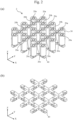
FIG. 2 is a set of perspective views illustrating a magnetic circuit section of the conveyance device according to the first embodiment. -
FIG. 3 is a set of perspective views illustrating the magnetic circuit section and an additional yoke of the conveyance device according to the first embodiment. -
FIG. 4 is a set of perspective views illustrating a magnetic circuit section and an additional yoke of a conveyance device according to a second embodiment. -
FIG. 5 is a set of perspective views illustrating a magnetic circuit section and an additional yoke of a conveyance device according to a third embodiment. -
FIG. 6 is a set of perspective views illustrating a magnetic circuit section and an additional yoke of a conveyance device according to a fourth embodiment. -
FIG. 7 is a set of perspective views illustrating the magnetic circuit section and the additional yoke of the conveyance device according to a modification of the fourth embodiment. -
FIG. 8 is a perspective view illustrating a cross-section of a magnetic circuit section of a conveyance device according to a fifth embodiment. -
FIG. 9 is a diagram illustrating advantages provided by the magnetic circuit section of the conveyance device according to the fifth embodiment. -
FIG. 10 is a diagram illustrating a configuration of a conveyance system. -
FIG. 11 is a diagram illustrating a configuration of a specimen analysis system. -
FIG. 12 is a diagram illustrating a configuration of a specimen pretreatment device. - Embodiments of a conveyance device provided by the present invention, a specimen analysis system with the conveyance device, and a specimen pretreatment device with the conveyance device are described below with reference to the accompanying drawings.
- A conveyance device according to a first embodiment will now be described.
FIG. 1 is a diagram illustrating a configuration of the conveyance device according to the first embodiment. Aconveyance device 1 conveys aconveyance target object 10 in an X-direction and a Y-direction.FIG. 2 is a set of perspective views illustrating a magnetic circuit section of the conveyance device according to the first embodiment. In a case where theconveyance target object 10 is to be conveyed a long distance, a plurality ofconveyance devices 1 depicted inFIG. 1 are connected in the X-direction and/or the Y-direction to achieve long-distance conveyance of theconveyance target object 10. Aconveyance surface 15 is provided on amagnetic circuit section 2, so that a permanent magnet 11 (seeFIG. 8 ) formed by a magnetic material embedded in theconveyance target object 10 moves over theconveyance surface 15. Themagnetic circuit section 2 depicted in part (a) ofFIG. 2 has three conveyance lines conveying theconveyance target object 10 in the X-direction and three conveyance lines conveying theconveyance target object 10 in the Y-direction. A winding 30 is wound around each of the plurality ofcylindrical teeth 20 formed by a magnetic material. It should be noted that theteeth 20 are general terms forteeth 20a to 20c. The plurality ofteeth 20 are magnetically coupled by ayoke 40 formed by a magnetic material on a side (-Z side) opposite theconveyance surface 15. - Part (b) of
FIG. 2 is a diagram illustrating theyoke 40 that is extracted from themagnetic circuit section 2. Theyoke 40 is shaped like a lattice and formed in correspondence with the three conveyance lines formed along the X-direction and with the three conveyance lines formed along the Y-direction. Theyoke 40 is formed by a magnetic material and magnetically coupled to the plurality ofteeth 20. Theyoke 40 supports the plurality ofteeth 20 such that the plurality ofteeth 20 extend in the Z-direction. - The
teeth 20 include theteeth 20a which are each adjacent to one tooth, theteeth 20b which are each adjacent to two teeth, and theteeth 20c which are each adjacent to four teeth. Theteeth 20a are disposed on the outermost side. Theteeth 20a are adjacent to a tooth on only one side in the X-direction or the Y-direction. Theteeth 20b are adjacent to teeth on both sides in the X-direction or the Y-direction. Theteeth 20c are adjacent to teeth on both sides in the-X direction and on both sides in the Y-direction. - The above-described
teeth teeth 20a on the outer side have fewer adjacent teeth than theteeth teeth 20a on the outer side than those in the case of theteeth conveyance target object 10 is relatively small in the case of theteeth 20a. Further, since the current value obtained upon application of a constant voltage varies between the winding 30 of theteeth 20a on the outer side and thewindings 30 of theteeth - Part (a) of
FIG. 3 is a perspective view illustrating the magnetic circuit section of the conveyance device according to the first embodiment. Part (b) ofFIG. 3 is a perspective view illustrating an additional yoke of the conveyance device according to the first embodiment. Theteeth 20a on the outer side of themagnetic circuit section 2 have a small number of adjacent teeth, so that magnetic properties deteriorate. Therefore, the magnetic properties of theteeth 20a on the outer side can be improved by installing theadditional yoke 45 formed by a magnetic material on the outer periphery of theyoke 40. In the first embodiment, theadditional yoke 45 is connected to the outer periphery of theyoke 40. However, theadditional yoke 45 need not necessarily be connected to the outer periphery of theyoke 40 and may be connected to an outer end of theyoke 40. In part (a) ofFIG. 3 , oneadditional yoke 45 is connected to onemagnetic circuit section 2. Alternatively, however, oneadditional yoke 45 may be connected to a plurality ofmagnetic circuit sections 2. For example, even in a case where the plurality ofmagnetic circuit sections 2 are disposed in the X-direction and/or the Y-direction, the teeth on the outer side whose magnetic performance deteriorates are present on the outer side of the disposed plurality ofmagnetic circuit sections 2. In this case, the magnetic properties of the disposed plurality ofmagnetic circuit sections 2 can easily be adjusted by installing theadditional yoke 45 or changing the size of theadditional yoke 45 after the plurality ofmagnetic circuit sections 2 are installed. Since operations performed outside themagnetic circuit section 2 are easier than operations performed inside themagnetic circuit section 2, it is easy to adjust the magnetic properties with theadditional yoke 45. Further, the magnetic properties of themagnetic circuit section 2 can be changed by replacing theadditional yoke 45 with an additional yoke of different dimensions. As a result, in a case where the mass or the subject of theconveyance target object 10 is changed, the magnetic properties of themagnetic circuit section 2 can easily be changed according to theconveyance target object 10. - The conveyance device according to a second embodiment will now be described with reference to
FIG. 4 . Component elements similar to those in the first embodiment will not be redundantly described. Part (a) ofFIG. 4 is a perspective view illustrating the magnetic circuit section of the conveyance device according to the second embodiment. Part (b) ofFIG. 4 is a perspective view illustrating the additional yoke of the conveyance device according to the second embodiment. Theteeth 20a on the outer side of themagnetic circuit section 2 have one adjacent tooth only in the X- or Y-direction. Therefore, in order to improve the magnetic properties of theteeth 20a on the outer side, themagnetic circuit section 2 in the second embodiment has theadditional yoke 45 that magnetically connects theteeth 20a on the outer side to a tooth being present in the XY-direction (diagonal direction) of theteeth 20a on the outside. Since the above-described configuration is adopted, theteeth 20a on the outer side are adjacent to three teeth. This improves the magnetic properties of theteeth 20a on the outer side. - Further, the ends of the
magnetic circuit section 2 are likely to bend due to their own weight. The bend of themagnetic circuit section 2 can also be suppressed by providing theadditional yoke 45 along the XY-direction (diagonal direction). - The conveyance device according to a third embodiment will now be described with reference to
FIG. 5 . The component elements similar to those in the first embodiment will not be redundantly described. Part (a) ofFIG. 5 is a perspective view illustrating the magnetic circuit section of the conveyance device according to the third embodiment. Part (b) ofFIG. 5 is a perspective view illustrating the additional yoke of the conveyance device according to the third embodiment. Theteeth 20a on the outer side of themagnetic circuit section 2 have one adjacent tooth only in the X- or Y-direction. Therefore, in order to improve the magnetic properties of theteeth 20a on the outer side, themagnetic circuit section 2 in the third embodiment has theadditional yoke 45 that is shaped like the letter T and configured to magnetically connect theteeth 20a on the outer side to a tooth being present in the XY-direction (diagonal direction) of theteeth 20a on the outside. Since the above-described configuration is adopted, theteeth 20a on the outer side are adjacent to three teeth. This improves the magnetic properties of theteeth 20a on the outer side. - Further, since the
additional yoke 45 is shaped like the letter T, the T-shapedadditional yoke 45 can be subsequently fitted into a U-shaped region existing on the outer side of theyoke 40. For example, after theconveyance device 1 is installed, the T-shapedadditional yoke 45 configured with tight-fit accuracy can be inserted by hitting it, for instance, with a hammer from the outer circumferential side. Therefore, after theconveyance device 1 is installed, the magnetic properties can easily be adjusted. Moreover, anadditional yoke 46 shaped like the letter L is coupled to a corner of themagnetic circuit section 2. Thisadditional yoke 46 may be molded integrally with theyoke 40 at the beginning. - The conveyance device according to a fourth embodiment will now be described with reference to
FIG. 6 . The component elements similar to those in the third embodiment will not be redundantly described. Part (a) ofFIG. 6 is a perspective view illustrating the magnetic circuit section of the conveyance device according to the fourth embodiment. Part (b) ofFIG. 6 is a perspective view illustrating the additional yoke of the conveyance device according to the fourth embodiment. Theteeth 20a on the outer side of themagnetic circuit section 2 have one adjacent tooth only in the X- or Y-direction. Therefore, in order to improve the magnetic properties of theteeth 20a on the outer side, themagnetic circuit section 2 in the fourth embodiment has theadditional yoke 45 that is shaped like the letter T and configured to magnetically connect theteeth 20a on the outer side to a tooth being present in the XY-direction (diagonal direction) of theteeth 20a on the outside. Since the above-described configuration is adopted, theteeth 20a on the outer side are adjacent to three teeth. This improves the magnetic properties of theteeth 20a on the outer side. - Further, the
additional yoke 46 shaped like the letter L is coupled to a corner of themagnetic circuit section 2. Furthermore, anadditional yoke 47 shaped like a cross is coupled to the center of themagnetic circuit section 2. - The conveyance device according to the fourth embodiment includes
auxiliary teeth 21 formed by a magnetic material that has no winding. A plurality ofauxiliary teeth 21 are disposed along the four sides of the conveyance device which is substantially quadrilateral. Theauxiliary teeth 21 are magnetically connected toadditional yokes auxiliary teeth 21 are disposed between theteeth 20a on the outer side. Theauxiliary teeth 21 each have a shorter length in the Z-direction than theteeth 20 wound with the winding 30. The number of teeth adjacent to theteeth 20a on the outer side is increased by providing theauxiliary teeth 21 between theteeth 20a on the outer side. Further, since theauxiliary teeth 21 are disposed between theteeth 20a on the outer side, it is possible to install a return path for the magnetic flux on the side (Z-direction) toward the conveyance surface (seeFIG. 1 ) of a tooth. This can further improve the magnetic properties. -
FIG. 7 illustrates a modification of the fourth embodiment. The conveyance device according to the modification illustrated inFIG. 7 includesauxiliary teeth auxiliary teeth 21a are magnetically connected to theadditional yoke 45 shaped like the letter T, and theauxiliary teeth 21b are magnetically connected to theadditional yoke 46 shaped like the letter L. Theauxiliary teeth 21a are disposed between theteeth 20a on the outer side. Theauxiliary teeth 21b are disposed on a corner of themagnetic circuit section 2. A plurality of theauxiliary teeth auxiliary teeth 21b installed on the corners of themagnetic circuit section 2 is larger than that of theauxiliary teeth 21a. Further, the length of theauxiliary teeth 21b in the Z-direction is greater than that of theauxiliary teeth 21a. - The
magnetic circuit section 2 in the modification of the fourth embodiment includes three conveyance lines conveying theconveyance target object 10 in the X-direction and three conveyance lines conveying theconveyance target object 10 in the Y-direction. Among the three conveyance lines for conveying theconveyance target object 10 in the X-direction, the teeth forming an inner conveyance line and the teeth forming an outer conveyance line have different magnetic properties. Further, among the three conveyance lines conveying theconveyance target object 10 in the Y-direction, the teeth forming an inner conveyance line and the teeth forming an outer conveyance line have different magnetic properties. Therefore, in order to improve the magnetic properties of the inner and outer conveyance lines, theauxiliary teeth additional yokes - Regarding an inductance of the
teeth 20a on the outer side, the inductance of theteeth 20a on the outer side decreases from the inside to the outside in the X- or Y-direction. Therefore, the magnetic properties can be improved by increasing at least one of the length and the diameter of theauxiliary teeth additional yokes magnetic circuit section 2 can be adjusted by using theauxiliary teeth magnetic circuit section 2 can be adjusted by use of theadditional yokes auxiliary teeth 21 are screwed into or inserted like a pin into the additional yokes 45. - The
conveyance device 1 according to a fifth embodiment will now be described with reference toFIG. 8 . The component elements similar to those in the first embodiment will not be redundantly described.FIG. 8 is a perspective view illustrating a cross-section of the magnetic circuit section of the conveyance device according to the fifth embodiment. InFIG. 8 , themagnetic circuit section 2 is partly cut away such that theteeth 20a on the outer side and the cross-sections of theteeth teeth 20a on the outer side of themagnetic circuit section 2 and theteeth yoke 40. Further, theconveyance target object 10 includes apermanent magnet 11 and aholder cover 12. Theholder cover 12 is formed by a magnetic material that holds thepermanent magnet 11 and suppresses leakage of magnetic flux. Furthermore, theadditional yoke 45 formed by a magnetic material is provided underneath the outer end of theteeth 20a on the outer side. As described above, the magnetic properties of themagnetic circuit section 2 can be improved by installing theadditional yoke 45 only underneath theteeth 20a on the outer side. In the present embodiment, the thickness of the entire yoke in the Z-direction is increased by installing theadditional yoke 45 underneath theteeth 20a on the outer side. However, since the same advantages can be obtained by increasing the cross-sectional area of a magnetic path, the thickness or width of the entire yoke may be increased by use of theadditional yoke 45. For example, the U-shapedadditional yoke 45 may alternatively be fitted into theyoke 40 from below or may be placed over theyoke 40 from above. Moreover, theadditional yoke 45 may alternatively be coupled to theyoke 40 by screwing or welding. -
FIG. 9 depicts the effect of magnetic property improvement by the present embodiment. InFIG. 9 , the horizontal axis represents the value of current (the rated value is expressed as 1.0 p.u.) flowing through the winding of target teeth, and the vertical axis represents inductance characteristics (expressed in p.u. notation) at a time of a minute current change in the value of current. Theinductance characteristics 61 of theteeth 20a on the outer side are different from theinductance characteristics 60 of theteeth 20b or theteeth 20c on the inner side due to difference in the number of adjacent teeth. Therefore, theadditional yoke 45 is provided in order to increase the degree of magnetic coupling between theteeth 20a on the outer side and theteeth 20b or theteeth 20c on the inner side. In a case where theadditional yoke 45 is installed, theinductance characteristics 62 of theteeth 20a on the outer side are closer to theinductance characteristics 60 of theteeth 20b or theteeth 20c on the inner side than theinductance characteristics 61 of theteeth 20a on the outer side. The thickness of theadditional yoke 45 is equivalent to that of theyoke 40. That is, the thickness of the combination of theyoke 40 and theadditional yoke 45 is two times greater than that of a portion where only theyoke 40 is provided. Further, the improvement in the magnetic properties of themagnetic circuit section 2 by theadditional yoke 45 can be adjusted by changing, for example, the shape, the width, the thickness, the material, or the processing method of theadditional yoke 45. -
FIG. 10 is a diagram illustrating an example of a configuration of a conveyance system for conveying theconveyance target object 10. Thepermanent magnet 11 of theconveyance target object 10 is conveyed on theconveyance surface 15 installed on themagnetic circuit section 2. The conveyance system depicted inFIG. 10 is a system that estimates the location of theconveyance target object 10 on the conveyance surface from the relation between the voltage applied to the winding and the current flowing through the winding. The conveyance system connects acurrent detection section 55 to each of thewindings 30 and estimates the location of theconveyance target object 10 on the basis of pieces of information from a plurality ofcurrent detection sections 55. Adrive circuit 50 applies a voltage to a coil to generate the thrust force that is to be applied to theconveyance target object 10. Acalculation section 53 controls thedrive circuit 50 according to a detected current value. - For example, a neodymium magnet or a ferrite magnet is used as the
permanent magnet 11. Alternatively, a magnet other than these magnets or a soft magnetic material may be used instead of thepermanent magnet 11. Further, instead of thepermanent magnet 11, a combination of thepermanent magnet 11 and the soft magnetic material may be used. It should be noted that the term "magnetic material" here denotes thepermanent magnet 11, other magnets, a soft magnetic material, or the combination of thepermanent magnet 11 and the soft magnetic material. Here, thepermanent magnet 11 is used as an example of the magnetic material. - The conveyance system requires relative location information regarding the
conveyance target object 10 and the winding 30. This is to ensure that an electromagnetic force generated in theteeth 20 by passing a current through the winding 30 is caused to efficiently act on theconveyance target object 10 and that theconveyance target object 10 is caused to be moved in a desired direction. For example, let us assume a case where theconveyance target object 10 is located above (directly above) one of the twowindings 30. Even in a case where a voltage is applied to the winding 30 directly below theconveyance target object 10, no force (thrust force) in a conveyance direction is applied to theconveyance target object 10. Meanwhile, when a voltage is applied to the winding 30 located at a position at which theconveyance target object 10 is not above (directly above) the winding 30 (the winding 30 that is not directly below the conveyance target object 10), a force for drawing theconveyance target object 10 toward the winding 30 is generated to generate a force (thrust force) in the conveyance direction. That is, a force in the conveyance direction can efficiently be applied to theconveyance target object 10 by applying a voltage to a desired winding 30. Further, the orientation (direction) of the force to be applied in the conveyance direction can be controlled by selecting the winding 30 to which the voltage is to be applied. - Detection of the location of the
conveyance target object 10 will now be described. In a case where theconveyance target object 10 is above the winding 30 depicted in the front inFIG. 10 , a magnetic field created by thepermanent magnet 11 acts on the winding 30. In this instance, the magnetic field acting on the winding 30 near theconveyance target object 10 and the magnetic field acting on the winding 30 far from theconveyance target object 10 differ in magnitude. That is, the magnitude of the magnetic field acting on the winding 30 varies with the relative locations of theconveyance target object 10 and the winding 30. - The
teeth 20 are formed by a magnetic material and have such a property that the magnetic flux configured to pass through theteeth 20 does not easily pass through theteeth 20 when the magnetic flux increases. Here, when a voltage is applied to the winding 30 to cause a current to flow, a magnetic flux (magnetic field) generated by the current is generated in theteeth 20. Therefore, a magnetic flux (magnetic field) generated by thepermanent magnet 11 and a magnetic flux (magnetic field) generated by the current flowing through the winding 30 are generated in theteeth 20. In general, when a current is passed through the winding 30, a magnetic field is generated around the winding 30, and the resulting magnetic flux is proportional to the value of the current passed. The constant of such proportionality is called inductance. When the magnetic field from thepermanent magnet 11 is present, magnetic saturation occurs in the winding 30 to reduce magnetic permeability. This results in a change in the current flowing through the winding 30. - In a case where a voltage is applied to the winding 30, an inductance L can be calculated by detection of the current flowing through the winding 30 and the way the current flows. More specifically, upon detection of the inductance L of the winding 30 which varies with the location of the
permanent magnet 11, the location of thepermanent magnet 11 affecting the inductance L can be determined. Therefore, thedrive circuit 50 is connected to the winding 30, and the current detection section 55 (e.g., a resistor) for detecting the value of the current flowing through the winding 30 is provided. Subsequently, a voltage is applied to the winding 30 by thedrive circuit 50, then a current value generated by the applied voltage is detected by thecurrent detection section 55, and the detected current value is read by thecalculation section 53. - If the
teeth teeth 20a on the outer side differ in inductance characteristics, it will affect the estimation of the location of thepermanent magnet 11 and the generation of thrust force. More specifically, such difference affects conveyance stability of theconveyance target object 10 and operational requirements necessary for conveyance (e.g., conveyance speed, unevenness of conveyance speed, and acceleration/deceleration characteristics). Therefore, theadditional yokes additional yokes teeth teeth 20a on the outer side causes, for example, a significant location estimation error and a delay in the control of thrust force. Therefore, in the conveyance system, it is important to reduce the differences in inductance characteristics and thrust force characteristics of the individual teeth in order to achieve stable conveyance. Consequently, being able to improve and adjust the magnetic properties for the individual locations of the teeth leads to the implementation of a high-performance conveyance device. - An overall configuration of a
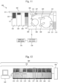
specimen analysis system 100 will now be described with reference toFIG. 11. FIG. 11 is a diagram schematically illustrating the overall configuration of thespecimen analysis system 100. - Described with reference to
FIG. 11 , thespecimen analysis system 100 is a device which dispenses a specimen and a reagent into a reaction container, allows them to react with each other, and measures the liquid resulting from the reaction. Thespecimen analysis system 100 includes aloading section 101, an emergencyrack loading port 113, aconveyance line 102, abuffer 104, ananalysis section 105, astorage section 103, adisplay section 118, and acontrol section 120. - The
loading section 101 is a place where aspecimen rack 111 is to be installed. Thespecimen rack 111 stores a plurality ofspecimen containers 122 that contain biological samples such as blood and urine. The emergencyrack loading port 113 is a place for loading, into the device, a specimen rack (calibration rack) loaded with a standard solution and thespecimen rack 111 in which thespecimen containers 122 containing specimens in need of urgent analysis are stored. - The
buffer 104 holds a plurality ofspecimen racks 111 conveyed by theconveyance line 102, in such a manner that the order of dispensing the specimens in the specimen racks 111 can be changed. Theanalysis section 105 analyzes the specimens that are conveyed from thebuffer 104 through aconveyor line 106. Thestorage section 103 holds the specimen racks 111 that accommodate thespecimen containers 122 containing the specimens that have been analyzed in theanalysis section 105. Theconveyance line 102 is a line for conveying the specimen racks 111 installed in theloading section 101, and has a configuration equivalent to that of any one of the conveyance devices according to the first to fifth embodiments which have been described above. In the specimen analysis system, thepermanent magnet 11 is disposed on the back side of thespecimen rack 111. That is, thespecimen rack 111 acts as theconveyance target object 10. - The
analysis section 105 includes theconveyor line 106, areaction disk 108, aspecimen dispensing nozzle 107, areagent disk 110, areagent dispensing nozzle 109, acleaning mechanism 112, areagent tray 114, areagent ID reader 115, areagent loader 116, and aspectrophotometer 121. Theconveyor line 106 is a line that loads the specimen racks 111 which are held in thebuffer 104 into theanalysis section 105. - The
reaction disk 108 includes a plurality of reaction containers. Thespecimen dispensing nozzle 107 dispenses the specimens from thespecimen containers 122 to the reaction containers of thereaction disk 108 by rotational driving or vertical driving. Thereagent disk 110 holds a plurality of reagent bottles. Thereagent dispensing nozzle 109 dispenses reagents from the reagent bottles of thereagent disk 110 to the reaction containers of thereaction disk 108. Thecleaning mechanism 112 cleans the reaction containers of thereaction disk 108. Thespectrophotometer 121 measures the absorbance of a reaction solution by measuring transmitted light obtained from a light source (not depicted) through the reaction solution in the reaction container. - The
reagent tray 114 is a member on which a reagent is placed when the reagent is to be registered in thespecimen analysis system 100. Thereagent ID reader 115 is an apparatus for acquiring reagent information by reading a reagent ID assigned to the reagent placed on thereagent tray 114. Thereagent loader 116 is an apparatus that loads the reagent into thereagent disk 110. - The
display section 118 is a display apparatus for displaying the result of analysis of the concentration of a predetermined component in a liquid specimen such as blood or urine. Thecontrol section 120 is formed by a computer including, for example, a CPU, a ROM, a RAM, and a storage and controls the operation of each mechanism in thespecimen analysis system 100. Thecontrol section 120 performs arithmetic processing to determine the concentration of a predetermined component in a specimen such as blood or urine. - A specimen analysis process performed by the
specimen analysis system 100 is described below. First, thespecimen rack 111 is installed in theloading section 101 or in the emergencyrack loading port 113 and is loaded by theconveyance line 102 into thebuffer 104 which can randomly be accessed. Thespecimen analysis system 100 uses theconveyor line 106 to load, into theanalysis section 105, thespecimen rack 111 that is stored in thebuffer 104 and assigned the highest priority according to priority rules. - Having arrived at the
analysis section 105, thespecimen rack 111 is transferred by theconveyor line 106 to a specimen separation position near thereaction disk 108. Thespecimen dispensing nozzle 107 separates the specimen from thespecimen containers 122 on thespecimen rack 111 and dispenses the specimen into the reaction container of thereaction disk 108. Thespecimen dispensing nozzle 107 performs separation of the specimen as many times as necessary according to requested analysis items for the specimen. Thespecimen dispensing nozzle 107 separates the specimen from all thespecimen containers 122 mounted on thespecimen rack 111. When a separation process is completed for all thespecimen containers 122, thespecimen rack 111 is transferred to thebuffer 104. Further, upon completion of all specimen separation processes including an automatic re-examination, thespecimen rack 111 is transferred to thestorage section 103 by theconveyor line 106 and theconveyance line 102. - Further, the reagent used for analysis is separated from a reagent bottle on the
reagent disk 110 by thereagent dispensing nozzle 109. The separated reagent is then dispensed into the reaction container into which the specimen is previously dispensed. Subsequently, a stirring mechanism (not depicted) stirs a liquid mixture of the specimen and the reagent in the reaction container. Light generated from the light source is transmitted through the reaction container containing the stirred liquid mixture, and the light intensity of the transmitted light is measured by thespectrophotometer 121. The light intensity measured by thespectrophotometer 121 is sent to thecontrol section 120 through an A/D converter and an interface. Thecontrol section 120 then performs calculations to determine the concentration of a predetermined component in a liquid specimen such as blood or urine, and displays the result, for example, on thedisplay section 118 or stores the result in the storage section (not depicted). - It should be noted that the
specimen analysis system 100 does not need to include all the component elements depicted inFIG. 11 . Thespecimen analysis system 100 can additionally include pretreatment units as needed and omit some units and component elements. Further, theanalysis section 105 need not always be used for biochemical analysis only, and may be used for immunological analysis as well. Furthermore, thespecimen analysis system 100 may include two ormore analysis sections 105. The number ofanalysis sections 105 is not limited to one. - An overall configuration of a
specimen pretreatment device 150 will now be described with reference toFIG. 12. FIG. 12 is a diagram illustrating the overall configuration of thespecimen pretreatment device 150. Described with reference toFIG. 12 , thespecimen pretreatment device 150 performs various pretreatments necessary for specimen analysis. Thespecimen pretreatment device 150 includes acapping unit 152, aspecimen storage unit 153, anempty holder stacker 154, aspecimen loading unit 155, acentrifugation unit 156, a liquidvolume measurement unit 157, an uncappingunit 158, a child specimencontainer preparation unit 159, adispensing unit 160, atransfer unit 161, and anoperation section PC 163. Theoperation section PC 163 controls the operations of a plurality of the above-mentioned units. - The
specimen analysis system 100 which performs qualitative and quantitative analysis of components of the specimen is connected to thespecimen pretreatment device 150 as a destination for transferring the specimen pretreated by thespecimen pretreatment device 150. Thespecimen loading unit 155 loads thespecimen container 122 which contains the specimen into thespecimen pretreatment device 150. Thecentrifugation unit 156 performs centrifugation on the loadedspecimen container 122. The liquidvolume measurement unit 157 measures the liquid volume of the specimen contained in thespecimen container 122. The uncappingunit 158 opens the cap of the loadedspecimen container 122. The child specimencontainer preparation unit 159 makes preparations necessary for dispensing the specimen contained in the loadedspecimen container 122 into the dispensingunit 160 of the following stage. The dispensingunit 160 subdivides the centrifuged specimen for analysis to be made, for example, by the specimen analysis system, and attaches, for example, barcodes to thespecimen containers 122 containing the subdivided specimens (thespecimen containers 122 containing the subdivided specimens are hereinafter referred to as the child specimen containers 122). Thetransfer unit 161 sorts thechild specimen containers 122 resulting from dispensing, and prepares them for transfer to thespecimen analysis system 100. Thecapping unit 152 caps thespecimen containers 122 and thechild specimen containers 122. Thespecimen storage unit 153 stores the cappedspecimen containers 122. - The conveyance device according to any one of the first to fifth embodiments can be used as a mechanism for conveying a specimen holder and the specimen rack that hold the
specimen containers 122 between the above-described units and between thespecimen pretreatment device 150 and thespecimen analysis system 100. It should be noted that thespecimen pretreatment device 150 does not need to include all of the above-described component elements and can omit some units and component elements. Further, thespecimen pretreatment device 150 may include units other than the units described above. - Furthermore, the specimen analysis system according to the present embodiment may be a
system 200 including thespecimen pretreatment device 150 and thespecimen analysis system 100 as depicted inFIG. 12 . In this case, not only within each system but also between thesystem 200 and thesystem 200 may be connected by theconveyance device 1 according to the first to fifth embodiments described above. - Moreover, the foregoing embodiments have been described on the assumption that the
specimen rack 111 holding fivespecimen containers 122 containing specimens is conveyed as the conveyance target object. However, in addition to thespecimen rack 111 holding fivespecimen containers 122, a specimen holder holding twospecimen containers 122 can be conveyed as the conveyance target object. - The
specimen analysis systems specimen pretreatment device 150 include theconveyance device 1 according to the first to fifth embodiments. This makes it possible to reduce the dependence of the magnitude of the thrust force at the time of conveyance and stoppage of thespecimen rack 111 and the specimen holder on the location of thespecimen rack 111 and the sample holder. Further, it is possible to provide theconveyance device 1 in which the detected value and the change value of the current necessary for detecting the locations of thespecimen rack 111 and the specimen holder are stable. That is, it is possible to implement theconveyance device 1 in which thespecimen rack 111 and the specimen holder are highly controllable and the locations of thespecimen rack 111 and the specimen holder are estimated with high accuracy. - It should be noted that the present invention is not limited to the foregoing embodiments and may be variously modified. The foregoing embodiments have been described in detail to facilitate the understanding of the present invention and do not need to include all the component elements described above.
- Further, some component elements of an embodiment may be replaced by the component elements of another embodiment, and the component elements of an embodiment can be added to the component elements of another embodiment. Furthermore, some component elements of each embodiment may be subjected to addition of other component elements, deletion, or replacement by other component elements.
- For example, the first to fifth embodiments have been described on the assumption that the
specimen rack 111 and the specimen holder are handled as the conveyance target object to be conveyed by theconveyance device 1. However, the conveyance target object is not limited to, for example, racks and holders holding thespecimen containers 122. A variety of objects that are required to be conveyed on a large scale can be handled as the conveyance target object. - Moreover, the first to fourth embodiments have been described on the assumption that the
additional yoke 45 is separate from theyoke 40. However, theadditional yoke 45 and theyoke 40 may integrally be molded. -
- 1: Conveyance device
- 2: Magnetic circuit section
- 10: Conveyance target object
- 11: Permanent magnet
- 12: Holder cover
- 15: Conveyance surface
- 20: Teeth
- 20a: Teeth on outer side
- 20b, 20c: Teeth on inner side
- 21: Auxiliary teeth
- 21a, 21b: Auxiliary teeth
- 30: Winding
- 40: Yoke
- 45, 46, 47: Additional yoke
- 50: Drive circuit
- 53: Calculation section
- 55: Current detection section
- 60: Inductance characteristics of teeth on inner side
- 61: Inductance characteristics of teeth on outer side
- 62: Inductance characteristics of teeth on outer side when additional yoke is installed
- 100: Specimen analysis system
- 101: Loading section
- 102: Conveyance line
- 103: Storage section
- 104: Buffer
- 105: Analysis section
- 106: Conveyor line
- 107: Specimen dispensing nozzle
- 108: Reaction disk
- 109: Reagent dispensing nozzle
- 110: Reagent disk
- 111: Specimen rack
- 112: Cleaning mechanism
- 113: Emergency rack loading port
- 114: Reagent tray
- 115: Reagent ID reader
- 116: Reagent loader
- 118: Display section
- 120: Control section
- 121: Spectrophotometer
- 122: Specimen container, child specimen container
- 150: Specimen pretreatment device
- 152: Capping unit
- 153: Specimen storage unit
- 154: Holder stacker
- 155: Specimen loading unit
- 156: Centrifugation unit
- 157: Liquid volume measurement unit
- 158: Uncapping unit
- 159: Child specimen container preparation unit
- 160: Dispensing unit
- 161: Transfer unit
- 163: Operation section PC
- 200: Specimen analysis system
Claims (14)
- A conveyance device for conveying a conveyance target object having a magnetic material, the conveyance device comprising:a plurality of teeth formed by a magnetic material;a plurality of windings wound around each of the plurality of teeth;a yoke in a shape of a lattice formed by a magnetic material that is magnetically connected to the plurality of teeth in order to support the plurality of teeth; andan additional yoke formed by a magnetic material that is magnetically connected to an outer end of a yoke.
- The conveyance device according to claim 1, wherein the additional yoke is coupled to an outer periphery of the yoke.
- The conveyance device according to claim 1, wherein the additional yoke is molded integrally with the yoke.
- The conveyance device according to claim 1, wherein the additional yoke magnetically connects the teeth on an outer side to other teeth.
- The conveyance device according to claim 4, wherein the additional yoke magnetically connects the teeth on the outer side to the teeth on an inner side.
- The conveyance device according to claim 4, wherein the additional yoke magnetically connects the teeth on the outer side to at least two other teeth.
- The conveyance device according to claim 4, wherein the additional yoke magnetically connects at least two of the teeth on the outer side with each other.
- The conveyance device according to claim 1, wherein auxiliary teeth formed by a magnetic material wound with no winding is magnetically connected to the additional yoke.
- The conveyance device according to claim 8, wherein a height of the auxiliary teeth is less than a height of the teeth wound with the windings.
- The conveyance device according to claim 8, wherein a plurality of the auxiliary teeth are disposed along one side of the conveyance device substantially shaped like a quadrilateral and become thicker and/or longer from a center of the one side toward a corner.
- The conveyance device according to claim 1, wherein a width of the additional yoke increases from a center of one side of the conveyance device substantially shaped like a quadrilateral toward a corner.
- The conveyance device according to any one of claims 1 to 11, wherein a location of the conveyance target object is detected on a basis of a current value of each winding.
- A specimen analysis system comprising:
the conveyance device according to claim 1. - A specimen pretreatment device comprising:
the conveyance device according to claim 1.
Applications Claiming Priority (2)
| Application Number | Priority Date | Filing Date | Title |
|---|---|---|---|
| JP2021138374A JP7692765B2 (en) | 2021-08-26 | 2021-08-26 | TRANSPORTATION DEVICE, SAMPLE ANALYSIS SYSTEM INCLUDING TRANSPORTATION DEVICE, AND SAMPLE PRE-TREATMENT DEVICE INCLUDING TRANSPORTATION DEVICE |
| PCT/JP2022/029470 WO2023026777A1 (en) | 2021-08-26 | 2022-08-01 | Transport device, specimen analysis system comprising transport device, and specimen pre-treatment device comprising transport device |
Publications (2)
| Publication Number | Publication Date |
|---|---|
| EP4393856A1 true EP4393856A1 (en) | 2024-07-03 |
| EP4393856A4 EP4393856A4 (en) | 2025-08-06 |
Family
ID=85322993
Family Applications (1)
| Application Number | Title | Priority Date | Filing Date |
|---|---|---|---|
| EP22861068.9A Pending EP4393856A4 (en) | 2021-08-26 | 2022-08-01 | TRANSPORT DEVICE, SAMPLE ANALYSIS SYSTEM WITH TRANSPORT DEVICE AND SAMPLE PRETREATMENT DEVICE WITH TRANSPORT DEVICE |
Country Status (5)
| Country | Link |
|---|---|
| US (1) | US20250074721A1 (en) |
| EP (1) | EP4393856A4 (en) |
| JP (1) | JP7692765B2 (en) |
| CN (1) | CN117651872A (en) |
| WO (1) | WO2023026777A1 (en) |
Families Citing this family (1)
| Publication number | Priority date | Publication date | Assignee | Title |
|---|---|---|---|---|
| JP2025161371A (en) * | 2024-04-12 | 2025-10-24 | 株式会社日立ハイテク | Specimen transport device, specimen analysis system, and specimen pretreatment device |
Family Cites Families (11)
| Publication number | Priority date | Publication date | Assignee | Title |
|---|---|---|---|---|
| JPH1159901A (en) * | 1997-08-11 | 1999-03-02 | Murata Mach Ltd | Carrier moving device |
| JPH1169764A (en) * | 1997-08-21 | 1999-03-09 | Nikon Corp | Positioning apparatus and exposure apparatus having the same |
| JP2001008431A (en) * | 1999-06-18 | 2001-01-12 | Yaskawa Electric Corp | Linear motor |
| JP2001217183A (en) * | 2000-02-04 | 2001-08-10 | Nikon Corp | Motor apparatus, stage apparatus, exposure apparatus, and device manufacturing method |
| JP2006304438A (en) * | 2005-04-19 | 2006-11-02 | Iai:Kk | Linear motor |
| EP3006943B1 (en) * | 2014-10-07 | 2020-04-22 | Roche Diagniostics GmbH | Module for a laboratory sample distribution system, laboratory sample distribution system and laboratory automation system |
| JP6597705B2 (en) * | 2016-06-03 | 2019-10-30 | 株式会社デンソー | Rotating electric machine |
| JP7325184B2 (en) | 2018-12-27 | 2023-08-14 | 株式会社日立ハイテク | Transport device, sample analysis system equipped with the same, sample pretreatment device |
| JP7319096B2 (en) * | 2019-06-12 | 2023-08-01 | 株式会社日立ハイテク | Conveyor |
| JP7236981B2 (en) * | 2019-10-28 | 2023-03-10 | 株式会社日立ハイテク | Transported object, container carrier and transport device |
| JP7304831B2 (en) * | 2020-02-18 | 2023-07-07 | 株式会社日立ハイテク | Sample analysis system having transport device and transport device |
-
2021
- 2021-08-26 JP JP2021138374A patent/JP7692765B2/en active Active
-
2022
- 2022-08-01 WO PCT/JP2022/029470 patent/WO2023026777A1/en not_active Ceased
- 2022-08-01 US US18/294,317 patent/US20250074721A1/en active Pending
- 2022-08-01 EP EP22861068.9A patent/EP4393856A4/en active Pending
- 2022-08-01 CN CN202280050467.XA patent/CN117651872A/en active Pending
Also Published As
| Publication number | Publication date |
|---|---|
| US20250074721A1 (en) | 2025-03-06 |
| JP2023032321A (en) | 2023-03-09 |
| WO2023026777A1 (en) | 2023-03-02 |
| EP4393856A4 (en) | 2025-08-06 |
| CN117651872A (en) | 2024-03-05 |
| JP7692765B2 (en) | 2025-06-16 |
Similar Documents
| Publication | Publication Date | Title |
|---|---|---|
| US11851282B2 (en) | Conveying device, sample analysis system and sample pretreatment device including the conveying device, and method for conveying conveyance object | |
| JP7107866B2 (en) | Conveying device and conveying method of conveyed object | |
| JP7319096B2 (en) | Conveyor | |
| CN112840214A (en) | Transport device, sample analysis system and sample preprocessing device equipped with the same | |
| EP3937359A1 (en) | Conveying device, and sample analysis system and sample preprocessing device comprising same | |
| EP4324772B1 (en) | Conveying device, and analyte analysis system | |
| US20250074721A1 (en) | Transport Device, Specimen Analysis System Comprising Transport Device, and Specimen Pre-Treatment Device Comprising Transport Device | |
| JP7701214B2 (en) | TRANSPORTATION DEVICE, SAMPLE ANALYSIS SYSTEM INCLUDING TRANSPORTATION DEVICE, AND SAMPLE PRE-TREATMENT DEVICE INCLUDING TRANSPORTATION DEVICE | |
| JP7545260B2 (en) | Specimen transport device, specimen analysis system, and specimen pretreatment device | |
| WO2020255538A1 (en) | Transport device and transport method | |
| WO2025134436A1 (en) | Specimen conveying device, specimen analysis system, and specimen pretreatment device | |
| WO2025216184A1 (en) | Specimen conveyance device, specimen analysis system, and specimen pretreatment device | |
| JP2022104723A (en) | Transport device, specimen analysis system comprising the same, and specimen pretreatment device |
Legal Events
| Date | Code | Title | Description |
|---|---|---|---|
| STAA | Information on the status of an ep patent application or granted ep patent |
Free format text: STATUS: THE INTERNATIONAL PUBLICATION HAS BEEN MADE |
|
| PUAI | Public reference made under article 153(3) epc to a published international application that has entered the european phase |
Free format text: ORIGINAL CODE: 0009012 |
|
| STAA | Information on the status of an ep patent application or granted ep patent |
Free format text: STATUS: REQUEST FOR EXAMINATION WAS MADE |
|
| 17P | Request for examination filed |
Effective date: 20240201 |
|
| AK | Designated contracting states |
Kind code of ref document: A1 Designated state(s): AL AT BE BG CH CY CZ DE DK EE ES FI FR GB GR HR HU IE IS IT LI LT LU LV MC MK MT NL NO PL PT RO RS SE SI SK SM TR |
|
| DAV | Request for validation of the european patent (deleted) | ||
| DAX | Request for extension of the european patent (deleted) | ||
| A4 | Supplementary search report drawn up and despatched |
Effective date: 20250708 |
|
| RIC1 | Information provided on ipc code assigned before grant |
Ipc: B65G 54/02 20060101AFI20250702BHEP Ipc: G01N 35/04 20060101ALI20250702BHEP Ipc: H02K 41/02 20060101ALI20250702BHEP |