EP4393849A1 - Material transportation carrier, carrying apparatus, drying system, and control method - Google Patents
Material transportation carrier, carrying apparatus, drying system, and control method Download PDFInfo
- Publication number
- EP4393849A1 EP4393849A1 EP22958958.5A EP22958958A EP4393849A1 EP 4393849 A1 EP4393849 A1 EP 4393849A1 EP 22958958 A EP22958958 A EP 22958958A EP 4393849 A1 EP4393849 A1 EP 4393849A1
- Authority
- EP
- European Patent Office
- Prior art keywords
- push
- pallet
- transportation vehicle
- pull assembly
- material pallet
- Prior art date
- Legal status (The legal status is an assumption and is not a legal conclusion. Google has not performed a legal analysis and makes no representation as to the accuracy of the status listed.)
- Pending
Links
Images



Classifications
-
- F—MECHANICAL ENGINEERING; LIGHTING; HEATING; WEAPONS; BLASTING
- F26—DRYING
- F26B—DRYING SOLID MATERIALS OR OBJECTS BY REMOVING LIQUID THEREFROM
- F26B25/00—Details of general application not covered by group F26B21/00 or F26B23/00
- F26B25/001—Handling, e.g. loading or unloading arrangements
- F26B25/003—Handling, e.g. loading or unloading arrangements for articles
-
- B—PERFORMING OPERATIONS; TRANSPORTING
- B61—RAILWAYS
- B61D—BODY DETAILS OR KINDS OF RAILWAY VEHICLES
- B61D47/00—Loading or unloading devices combined with vehicles, e.g. loading platforms, doors convertible into loading and unloading ramps
-
- B—PERFORMING OPERATIONS; TRANSPORTING
- B60—VEHICLES IN GENERAL
- B60P—VEHICLES ADAPTED FOR LOAD TRANSPORTATION OR TO TRANSPORT, TO CARRY, OR TO COMPRISE SPECIAL LOADS OR OBJECTS
- B60P1/00—Vehicles predominantly for transporting loads and modified to facilitate loading, consolidating the load, or unloading
- B60P1/64—Vehicles predominantly for transporting loads and modified to facilitate loading, consolidating the load, or unloading the load supporting or containing element being readily removable
- B60P1/6418—Vehicles predominantly for transporting loads and modified to facilitate loading, consolidating the load, or unloading the load supporting or containing element being readily removable the load-transporting element being a container or similar
- B60P1/6436—Vehicles predominantly for transporting loads and modified to facilitate loading, consolidating the load, or unloading the load supporting or containing element being readily removable the load-transporting element being a container or similar the load-transporting element being shifted horizontally in a crosswise direction, combined or not with a vertical displacement
-
- F—MECHANICAL ENGINEERING; LIGHTING; HEATING; WEAPONS; BLASTING
- F26—DRYING
- F26B—DRYING SOLID MATERIALS OR OBJECTS BY REMOVING LIQUID THEREFROM
- F26B25/00—Details of general application not covered by group F26B21/00 or F26B23/00
- F26B25/06—Chambers, containers, or receptacles
- F26B25/063—Movable containers or receptacles, e.g. carts, trolleys, pallet-boxes
-
- F—MECHANICAL ENGINEERING; LIGHTING; HEATING; WEAPONS; BLASTING
- F26—DRYING
- F26B—DRYING SOLID MATERIALS OR OBJECTS BY REMOVING LIQUID THEREFROM
- F26B5/00—Drying solid materials or objects by processes not involving the application of heat
- F26B5/04—Drying solid materials or objects by processes not involving the application of heat by evaporation or sublimation of moisture under reduced pressure, e.g. in a vacuum
-
- F—MECHANICAL ENGINEERING; LIGHTING; HEATING; WEAPONS; BLASTING
- F26—DRYING
- F26B—DRYING SOLID MATERIALS OR OBJECTS BY REMOVING LIQUID THEREFROM
- F26B9/00—Machines or apparatus for drying solid materials or objects at rest or with only local agitation; Domestic airing cupboards
- F26B9/06—Machines or apparatus for drying solid materials or objects at rest or with only local agitation; Domestic airing cupboards in stationary drums or chambers
-
- F—MECHANICAL ENGINEERING; LIGHTING; HEATING; WEAPONS; BLASTING
- F27—FURNACES; KILNS; OVENS; RETORTS
- F27D—DETAILS OR ACCESSORIES OF FURNACES, KILNS, OVENS OR RETORTS, IN SO FAR AS THEY ARE OF KINDS OCCURRING IN MORE THAN ONE KIND OF FURNACE
- F27D3/00—Charging; Discharging; Manipulation of charge
-
- H—ELECTRICITY
- H01—ELECTRIC ELEMENTS
- H01M—PROCESSES OR MEANS, e.g. BATTERIES, FOR THE DIRECT CONVERSION OF CHEMICAL ENERGY INTO ELECTRICAL ENERGY
- H01M4/00—Electrodes
- H01M4/02—Electrodes composed of, or comprising, active material
- H01M4/04—Processes of manufacture in general
- H01M4/0471—Processes of manufacture in general involving thermal treatment, e.g. firing, sintering, backing particulate active material, thermal decomposition, pyrolysis
-
- B—PERFORMING OPERATIONS; TRANSPORTING
- B61—RAILWAYS
- B61C—LOCOMOTIVES; MOTOR RAILCARS
- B61C13/00—Locomotives or motor railcars characterised by their application to special systems or purposes
-
- F—MECHANICAL ENGINEERING; LIGHTING; HEATING; WEAPONS; BLASTING
- F27—FURNACES; KILNS; OVENS; RETORTS
- F27B—FURNACES, KILNS, OVENS OR RETORTS IN GENERAL; OPEN SINTERING OR LIKE APPARATUS
- F27B9/00—Furnaces through which the charge is moved mechanically, e.g. of tunnel type; Similar furnaces in which the charge moves by gravity
- F27B9/04—Furnaces through which the charge is moved mechanically, e.g. of tunnel type; Similar furnaces in which the charge moves by gravity adapted for treating the charge in vacuum or special atmosphere
- F27B9/042—Vacuum furnaces
-
- F—MECHANICAL ENGINEERING; LIGHTING; HEATING; WEAPONS; BLASTING
- F27—FURNACES; KILNS; OVENS; RETORTS
- F27D—DETAILS OR ACCESSORIES OF FURNACES, KILNS, OVENS OR RETORTS, IN SO FAR AS THEY ARE OF KINDS OCCURRING IN MORE THAN ONE KIND OF FURNACE
- F27D3/00—Charging; Discharging; Manipulation of charge
- F27D2003/0034—Means for moving, conveying, transporting the charge in the furnace or in the charging facilities
-
- H—ELECTRICITY
- H01—ELECTRIC ELEMENTS
- H01M—PROCESSES OR MEANS, e.g. BATTERIES, FOR THE DIRECT CONVERSION OF CHEMICAL ENERGY INTO ELECTRICAL ENERGY
- H01M2220/00—Batteries for particular applications
- H01M2220/20—Batteries in motive systems, e.g. vehicle, ship, plane
Definitions
- the present application relates to the technical field of batteries, and in particular, to a material transportation vehicle, a material carrying device, a material drying system and a control method, an electronic apparatus, a computer-readable storage medium, and a computer program product.
- the push-pull assembly further comprises a third push-pull assembly arranged on the carrying base and spaced apart from the first push-pull assembly and the second push-pull assembly.
- the second push-pull assembly is further configured to drive the material pallet to move between the second position and a second transition position.
- the third push-pull assembly is further configured to drive the material pallet to move between the second transition position and the third position.
- the second transition position is between the second position and the third position.
- the structure of the third push-pull assembly being consistent with that of the first push-pull assembly and that of the second push-pull assembly can simplify the types of parts and facilitate subsequent maintenance, while maintaining the consistency of the movement structures on two sides, thereby avoiding the imbalance caused by a large difference in stress between the driving structures on the two sides.
- the material is automatically moved from the loading position to a drying position by means of the material transportation vehicle, achieving the automatic processing of the feeding operation for drying, avoiding manual participation which causes excessive time consumption, and improving the production efficiency.
- the method for controlling a material drying system further comprises:
- the positioning member on the carrying base is driven to abut against the material pallet or the material contained on the material pallet in response to the material pallet being in the second position.
- an embodiment of the present application provides an electronic apparatus, comprising: at least one processor; and a memory communicatively connected to the at least one processor.
- the memory stores instructions executable by the at least one processor, and the instructions, when executed by the at least one processor, cause the at least one processor to perform a method for controlling a material drying system in the above embodiments.
- traction batteries are used more and more widely.
- the traction batteries are not only used in energy storage power systems such as hydroelectric power plants, thermal power plants, wind power plants and solar power plants, but also widely used in electric transportation means such as electric bicycles, electric motorcycles, and electric vehicles and in many fields such as military equipment and aerospace.
- energy storage power systems such as hydroelectric power plants, thermal power plants, wind power plants and solar power plants
- electric transportation means such as electric bicycles, electric motorcycles, and electric vehicles and in many fields such as military equipment and aerospace.
- market demand for the traction batteries is also expanding.
- moisture content is one of the important factors affecting the quality and performance of traction batteries, and an important means for controlling moisture is the use of a drying procedure.
- the current drying procedure is still in a semi-automated state, is complex to operate, has many manual participation steps, and takes too long time, significantly hindering the production efficiency and the manufacturing cost.
- the material pallet 103 may be configured to contain a material.
- the material may be a workpiece or module to be transported or processed, such as a battery cell.
- the material pallet 103 may contain a plurality of workpieces or modules at the same time.
- the plurality of workpieces or modules may be placed in a suitable manner and arranged according to the placement requirements during machining or processing.
- the plurality of battery cells may be stacked on the material pallet 103.
- the second position 120 may be a position directly above the carrying base 101.
- the first position 110 is a position in the same horizontal plane as the second position 120 and separated by a preset distance in the first direction X. It can be understood that, as shown in FIG.
- the first position 110 is a position that is staggered and separated by a certain distance from the second position 120 in the first direction X, and is located outside the material transportation vehicle 100.
- the absolute spatial positions of the first position 110 and the second position 120 will also change accordingly.
- the preset distance between the first position 110 and the second position 120 may also be set based on the actual usage scenario, so that driving the material pallet 103 to move between the first position 110 and the second position 120 can realize the movement of the material pallet 103 into and out of the carrying base 101 of the material transportation vehicle 100.
- the first direction X may be set according to the requirements of the specific movement direction.
- the process of moving the material pallet 103 out of the carrying base 101 is to move the material pallet from the second position 120 to the first transition position 111, and then move the material pallet from the first transition position 111 to the first position 110, so as to completely separate the material pallet 103 from the material transportation vehicle 100.
- the push-pull assembly 102 is further configured to drive the material pallet 103 to move between the second position 120 and the third position 130.
- the third position 130 and the second position 120 are located in the same horizontal plane, and the third position and the first position 110 are respectively located on two sides of the second position 120 in the first direction X.
- the material pallet 103 may be driven by the push-pull assembly 102 to move to two sides in the same direction or in opposite directions with respect to the first direction X, so that on either side of the carrying base 101 in the first direction X, the material pallet 103 can be moved in and out. That is, the material pallet may be moved in and out on the same side, or may be moved in on one side and out on the other side.
- the push-pull assembly 102 drives the material pallet 103 to move to two sides of the second position 120, so it is possible to get rid of the restriction of the specific orientation when a station is arranged, and to improve the applicable scope and the delivery efficiency of the device.
- the stress problem caused by an excessively long single-stage push-pull stroke can be well avoided.
- the push-pull stroke of each stage does not need to deviate too far from the carrying base, so there is no need to change the track configuration and the structural layout, but only need to make simple adjustments to the driving unit. This will not be constrained by the structural layout, the application scenarios can be expanded, and the operating efficiency of the device can be improved.
- the first push-pull assembly 104 comprises a first push-pull rod 1041, a first linear driving unit 1042 and a first rotary driving unit 1043.
- the first push-pull rod 1041 comprises a first rod body 1044 and a first engagement portion 1045 fixedly connected to the first rod body 1044.
- the first linear driving unit 1042 is in transmission connection with the first rod body 1044 to drive the first push-pull rod 1041 to move between the first position 110 and the first transition position 111.
- the first rotary driving unit 1043 is in transmission connection with the first rod body 1044, and the first rotary driving unit 1043 drives the first engagement portion 1045 to rotate, such that the first engagement portion 1045 engages with or disengages from the material pallet 103.
- the second push-pull assembly 105 comprises a second push-pull rod 1051, a second linear driving unit 1052 and a second rotary driving unit 1053.
- the second push-pull rod 1051 comprises a second rod body 1054 and at least one second engagement portion 1055 fixedly connected to the second rod body 1054.
- the second linear driving unit 1052 is in transmission connection with the second rod body 1054 to drive the second push-pull rod 1051 to move between the second position 120 and the first transition position 111.
- the second rotary driving unit 1053 is in transmission connection with the second rod body 1054, and the second rotary driving unit 1053 drives the at least one second engagement portion 1055 to rotate, such that the at least one second engagement portion 1055 engages with or disengages from the material pallet 103.
- the first push-pull rod 1041 moves linearly in the first direction X under the driving of the first linear driving unit 1042. After reaching a designated position, the first push-pull rod 1041 is driven by the first rotary driving unit 1043 to rotate, such that the first engagement portion 1045 engages with or disengages from the material pallet 103 through rotation, thereby achieving the detachable connection.
- the second push-pull rod 1051 also works on the same principle.
- the first linear driving unit 1042 and the second linear driving unit 1052 may be an electric motor and lead screw drive, or may be a telescopic cylinder drive.
- the first linear driving unit 1042 and the second linear driving unit 1052 may be the same or different.
- the first rotary driving unit 1043 and the second rotary driving unit 1053 may be an electric motor that transmits rotation through a belt or an electric motor that transmits rotation through gears.
- the first rotary driving unit 1043 and the second rotary driving unit 1053 may be the same or different.
- an upper surface of the carrying base 101 is provided with at least one first guide member 150 extending in the first direction X, and a bottom portion of the material pallet 103 is provided with at least one second guide member 160 corresponding to the at least one first guide member 150.
- the first direction X is perpendicular to an extension direction Y of the conveying track 201.
- the loading device 305 and the unloading device 306 may be manipulators.
- the manipulator grabs a material, such as a battery cell, and places the material on the material pallet 103 in the loading position or removes the material from the material pallet 103 in the unloading position.
- the loading position 310 refers to a position where the material pallet 103 is prepared to be transferred to the material transportation vehicle 100
- the unloading position 340 refers to a position where the material pallet 103 is placed after being moved out of the material transportation vehicle 100.
- the material is automatically moved from the loading position to the drying position by means of the material transportation vehicle, achieving the automatic processing of the feeding operation for drying, avoiding manual participation which causes excessive time consumption, and improving the production efficiency.
- the material transportation vehicle 100 needs to move to the place where the first position 110 or the third position 130 coincides with the unloading position 340, and then the push-pull assembly 102 drives the material pallet 103 to move from the second position 120 to the unloading position 340.
- the material transportation vehicle 100 may be configured to drive the material pallet 103 to always move on the same side of the carrying base 101, that is, the loading position 310, the drying position and the unloading position 340 are all located on the same side of the material transportation vehicle.
- the material transportation vehicle may be configured to drive the material pallet to move along two sides of the first direction of the carrying base, that is, the loading position, the drying position and the unloading position may be arbitrarily distributed on the two sides of the carrying base.
- the first push-pull assembly 104 and the third push-pull assembly 106 in the push-pull assembly 102 may also maintain an engagement connection with their corresponding engagement blocks when the material pallet 103 is located in the second position on the carrying base 101.
- the engagement connection structure between the push-pull assembly and the material pallet can provide a good limiting effect when the material pallet is transported, preventing the material pallet from turning over, and ensuring the smooth and safe transportation.
- the positioning member on the carrying base is driven to abut against the material pallet or the material contained on the material pallet in response to the material pallet being in the second position.
- the positioning member 107 may be driven to abut against the material pallet 103 or the material 140 in the extension direction of the conveying track. In this case, if the position of the material pallet deviates from the preset second position, the positioning member 107 cannot meet the preset abutment requirements, thereby sending an alarm signal to remind the operator to adjust the position of the material pallet.
- the positioning member can provide position determination and movement limit functions for the material pallet. Through position determination, it is possible to ensure that the material pallet does not shift or is adjusted in a timely manner after the shift occurs, avoiding apparatus failure caused by overturning during transportation. Moreover, during the transportation, the positioning member can provide contact abutment and limit in the extension direction of the conveying track. This, together with the limit of the push-pull assembly, can achieve limit in two directions in the horizontal plane, better ensuring the stability of transportation.
- an embodiment of the present application provides an electronic apparatus, comprising: at least one processor; and a memory communicatively connected to the at least one processor.
- the memory stores instructions executable by the at least one processor, and the instructions, when executed by the at least one processor, cause the at least one processor to perform a method for controlling a material drying system in the above embodiments.
- an embodiment of the present application provides a computer-readable storage medium, storing a computer program.
- the computer program is executed by a processor, a method for controlling a material drying system in the above embodiments is implemented.
- an embodiment of the present application further provides a computer program product, comprising a computer program.
- a computer program product comprising a computer program.
- the material carrying device comprises a conveying track 201, a material transportation vehicle 100 arranged on the conveying track 201, a driving device 202, and a material pallet 103 configured to contain a material.
- the conveying track 201 is arranged in a straight line, and the driving device 202 is arranged on the material transportation vehicle 100 to drive the material transportation vehicle 100 to move on the conveying track 201.
- the drying device 301 comprises a first vacuum drying furnace 302 and a second vacuum drying furnace 303 located on one side of the conveying track 201, and a third vacuum drying furnace 304 located on the other side of the conveying track 201.
- the loading device 305 is located at a first end of the conveying track 201, and the unloading device 306 is located at a second end of the conveying track 201.
- the feeding process of the material drying system 300 is as follows.
- the loading device 305 grabs a battery cell delivered by a feeding belt and places the battery cell in a stacked manner on the material pallet 103.
- the driving device 202 drives the material transportation vehicle 100 to move to the first end of the conveying track 201 until the first position corresponding to the carrying base 101 of the material transportation vehicle 100 coincides with the loading position 310.
- the first linear driving unit 1042 drives the first push-pull rod 1041 to move to the first position until the first engagement portion 1045 moves to the position where the first engagement block group 1032 is located.
- the first rotary driving unit 1043 drives the first push-pull rod 1041 to rotate, so as to engage the engagement groove on the first engagement portion 1045 with the first engagement block group 1032.
- the first linear driving unit 1042 drives the first push-pull rod 1041 to drive the material pallet 103 to move to the first transition position 111, and the first rotary driving unit 1043 drives the first push-pull rod 1041 to rotate to disengage the first engagement portion 1045 from the first engagement block group, thereby completing the first push-pull stage.
- the second linear driving unit 1052 drives the second push-pull rod 1051 to move until the second engagement portion 1055 moves to the position where the second engagement block group 1033 is located, and the second rotary driving unit 1053 drives the second push-pull rod 1051 to rotate, so as to engage the second engagement portion 1055 with the second engagement block group 1033.
- the second linear driving unit 1052 drives the second push-pull rod 1051 to drive the material pallet 103 to move from the first transition position 111 to the second position 120, completing the second push-pull stage.
- the positioning member 107 is driven to abut against the side of the material pallet 103, so as to provide limit and support for the material pallet 103 in the extension direction Y of the track.
- the driving device 202 drives the material transportation vehicle 100 to move along the conveying track 201 to the front of the first vacuum drying furnace 302, and the material transportation vehicle 100 moves along the conveying track 201 to maintain the engagement connection between the second engagement portion 1055 and the second engagement block group 1033.
- the third position 130 coincides with the first drying position 320 in the first vacuum drying furnace 302
- the material transportation vehicle 100 stops moving, and the positioning member 107 is separated from the material pallet 103 to cancel the limit.
- the discharging process of the material drying system 300 is as follows.
- the driving device 202 moves the material transportation vehicle 100 to the front of the third vacuum drying furnace 304 until the first position 110 coincides with the second drying position 330 in the third vacuum drying furnace 304.
- the push-pull assembly 102 drives the material pallet 103 to move from the second drying position 330 in the third vacuum drying furnace 304 to the second position 120, completing the movement of the material out of the third vacuum drying furnace 304.
- This process is substantially the same as the movement from the loading position 310 to the second position 120 in the feeding process.
- the positioning member 107 abuts against a side surface of the material pallet 103.
- the engagement state of the second engagement portion 1055 and the second engagement block group 1033 is maintained, and the driving device 202 moves the material transportation vehicle 100 to the front of the unloading position 340 until the first position 110 coincides with the unloading position 340.
- the material transportation vehicle 100 stops moving, and the positioning member 107 releases the abutment against the material pallet 103.
- the push-pull assembly 102 drives the material pallet 103 to move from the second position 120 to the unloading position 340. This process is substantially the same as the movement from the second position 120 to the first drying position 320 in the feeding process.
Landscapes
- Engineering & Computer Science (AREA)
- Mechanical Engineering (AREA)
- General Engineering & Computer Science (AREA)
- Transportation (AREA)
- Chemical Kinetics & Catalysis (AREA)
- General Chemical & Material Sciences (AREA)
- Electrochemistry (AREA)
- Chemical & Material Sciences (AREA)
- Manufacturing & Machinery (AREA)
- Health & Medical Sciences (AREA)
- Life Sciences & Earth Sciences (AREA)
- Molecular Biology (AREA)
- Automatic Assembly (AREA)
- Warehouses Or Storage Devices (AREA)
Abstract
Description
- The present application relates to the technical field of batteries, and in particular, to a material transportation vehicle, a material carrying device, a material drying system and a control method, an electronic apparatus, a computer-readable storage medium, and a computer program product.
- Achieving energy conservation and emission reduction is the key to the sustainable development of the automotive industry. Electric vehicles have become an important part of the sustainable development of the automotive industry due to their advantages in energy conservation and environmental protection. For the electric vehicles, the battery technology is an important factor to their development.
- With the continuous development of the new energy industry, the market has higher and higher requirements for the energy density of batteries. Especially today, when new energy vehicles are becoming more and more popular, batteries not only need to have excellent power performance but also need to have excellent cycle performance to maintain the endurance of the battery. Drying procedures are required during the preparation of traction batteries, which usually comprise drying of positive and negative electrode powders, drying of electrode plates and drying of battery cells. Drying generally takes a long time and involves many manual steps and time. Therefore, how to improve the operating efficiency while ensuring the production quality is of great significance for reducing the battery manufacturing cost.
- The present application is intended to solve at least one of the technical problems existing in the prior art. To this end, an objective of the present application is to provide a material transportation vehicle, a material carrying device, a material drying system and a control method, an electronic apparatus, a computer-readable storage medium, and a computer program product, in order to improve the operating efficiency of the manufacturing process.
- In a first aspect, an embodiment of the present application provides a material transportation vehicle, comprising: a carrying base, and a push-pull assembly arranged on the carrying base. The push-pull assembly is configured to drive a material pallet for containing a material to move between a first position and a second position. The second position is a position above the carrying base, and the first position is a position located in the same horizontal plane as the second position and separated from the second position by a preset distance in a first direction.
- In the technical solution of the embodiment of the present application, a push-pull assembly capable of driving the movement of the material pallet is arranged on the carrying base, so that the material pallet can be automatically moved into and out of the carrying base, thereby achieving automatic handling of material transportation, improving the production efficiency, and reducing the manufacturing cost.
- In some embodiments, the push-pull assembly comprises a first push-pull assembly and a second push-pull assembly. The first push-pull assembly is configured to be detachably connected to the material pallet and drive the material pallet to move between the first position and a first transition position. The second push-pull assembly is arranged spaced apart from the first push-pull assembly, and the second push-pull assembly is configured to be detachably connected to the material pallet and drive the material pallet to move between the second position and the first transition position. The first transition position is located between the first position and the second position.
- In the technical solution of the embodiments of the present application, by providing the first push-pull assembly and the second push-pull assembly to move the material pallet in a two-stage driving manner, the problem of insufficient stability of a single-stage driving structure can be avoided, and the movement range of the push-pull assembly can be reduced, so that the structural arrangement is more compact and the footprint is reduced.
- In some embodiments, the push-pull assembly is further configured to drive the material pallet to move between the second position and a third position. The third position and the second position are located in the same horizontal plane, and the third position and the first position are respectively located on two sides of the second position in the first direction.
- In the technical solution of the embodiments of the present application, the push-pull assembly drives the material pallet to move to two sides of the second position, so it is possible to get rid of the restriction of the specific orientation when a station is arranged, to improve the applicable scope and the delivery efficiency of the device, and to improve the operating efficiency of the device.
- In some embodiments, the first push-pull assembly comprises a first push-pull rod, a first linear driving unit and a first rotary driving unit. The first push-pull rod comprises a first rod body and a first engagement portion fixedly connected to the first rod body. The first linear driving unit is in transmission connection with the first rod body to drive the first push-pull rod to move between the first position and the first transition position. The first rotary driving unit is in transmission connection with the first rod body, and the first rotary driving unit drives the first engagement portion to rotate, such that the first engagement portion engages with or disengages from the material pallet. The second push-pull assembly comprises a second push-pull rod, a second linear driving unit and a second rotary driving unit. The second push-pull rod comprises a second rod body and at least one second engagement portion fixedly connected to the second rod body. The second linear driving unit is in transmission connection with the second rod body to drive the second push-pull rod to move between the second position and the first transition position. The second rotary driving unit is in transmission connection with the second rod body, and the second rotary driving unit drives the at least one second engagement portion to rotate, such that the at least one second engagement portion engages with or disengages from the material pallet.
- In the technical solution of the embodiments of the present application, the first push-pull assembly and the second push-pull assembly are respectively provided with a first engagement portion and a second engagement portion to engage with or disengage from the material pallet to achieve detachable connection, and in combination with the cooperation of the linear driving units and the rotary driving units, the first push-pull assembly and the second push-pull assembly can respectively engage with the material pallet and then push and pull the material pallet to move, thereby achieving two-stage driving, avoiding damage to the structure due to large stress and deformation caused by excessive distance during single-stage push and pull, and improving the structural stability and the safety of the device.
- In some embodiments, the push-pull assembly further comprises a third push-pull assembly arranged on the carrying base and spaced apart from the first push-pull assembly and the second push-pull assembly. The second push-pull assembly is further configured to drive the material pallet to move between the second position and a second transition position. The third push-pull assembly is further configured to drive the material pallet to move between the second transition position and the third position. The second transition position is between the second position and the third position.
- In the technical solution of the embodiments of the present application, the bidirectional movement of the material pallet is achieved by providing the third assembly, so that the second push-pull assembly can cooperate with the first push-pull assembly and the third push-pull assembly respectively such that the material pallet can be moved in a two-stage driving manner on two sides, thereby avoiding redundancy in structural design, improving the utilization rate of the device, and improving the operating efficiency.
- In some embodiments, the third push-pull assembly comprises a third push-pull rod, a third linear driving unit and a third rotary driving unit. The third push-pull rod comprises a third rod body and a third engagement portion fixedly connected to the third rod body. The third linear driving unit is in transmission connection with the third rod body, and the third linear driving unit is configured to drive the third push-pull rod to move between the third position and the second transition position. The third rotary driving unit is in transmission connection with the third rod body, and the third rotary driving unit is configured to drive the third engagement portion to rotate, such that the third engagement portion engages with or disengages from the material pallet.
- In the technical solution of the embodiments of the present application, the structure of the third push-pull assembly being consistent with that of the first push-pull assembly and that of the second push-pull assembly can simplify the types of parts and facilitate subsequent maintenance, while maintaining the consistency of the movement structures on two sides, thereby avoiding the imbalance caused by a large difference in stress between the driving structures on the two sides.
- In some embodiments, the first position and the third position are mirror symmetrical with respect to the second position, and the first transition position and the second transition position are mirror symmetrical with respect to the second position.
- In the technical solution of the embodiments of the present application, specifically arranging the first position and the third position, and the first transition position and the second transition position to be mirror symmetrical can more easily achieve positioning when moving between different sides, simplify the control logic of the driving units, and reduce the failure rate.
- In some embodiments, the material transportation vehicle further comprises: a positioning member fixedly connected to the carrying base. The positioning member is configured to abut against the material pallet or a material contained on the material pallet in response to the material pallet being in the second position.
- In the technical solution of the embodiments of the present application, by providing the positioning member to limit the material pallet or the material on the material pallet, the stability during transportation can be ensured and overturning can be avoided. Moreover, the positioning function of the positioning member can also be used to determine whether the position of the material pallet is in place. If the position of the material pallet is somewhat offset from the second position, the positioning member will send out an alarm signal because it cannot reach a preset positioning position, and then the position of the material pallet can be adjusted to avoid accidents during the transportation and ensure the transportation safety.
- In a second aspect, an embodiment of the present application provides a material carrying device, comprising: a material pallet configured to contain a material, a conveying track, and a material transportation vehicle in the above embodiments.
- In the technical solution of the embodiments of the present application, through the cooperation of the material transportation vehicle and the conveying track, long-distance transportation can be achieved, so that the transportation vehicle in the material carrying device can achieve the transfer of the material between different positions. Combined with processing apparatuses for different procedures, the automatic loading, unloading and transportation of the material in different processing procedures can be achieved to improve the operating efficiency for production.
- In some embodiments, an upper surface of the carrying base is provided with at least one first guide member extending in the first direction, and a bottom portion of the material pallet is provided with at least one second guide member corresponding to the at least one first guide member. The first direction is perpendicular to an extension direction of the conveying track.
- In the technical solution of the embodiments of the present application, the corresponding arrangement of the first guide member and the second guide member can provide a guidance for the material pallet during moving, to avoid deviation. Still further, the first guide member and the second guide member can also provide support in the vertical direction, so as to, when the material pallet moves, prevent all or part of the gravity from acting on the push-pull assembly, which causes the push-pull assembly to be deformed and damaged due to excessive force, thereby improving the structural reliability and stability of the device. Setting the first direction perpendicular to the extension direction of the track facilitates the arrangement of the moving space of the material pallet to avoid interference with other apparatuses, and also facilitates the control over the moving strokes of the loading and unloading of the material.
- In some embodiments, the bottom portion of the material pallet is provided with an engagement block, and the engagement block cooperates with the push-pull assembly to achieve a detachable connection between the material pallet and the material transportation vehicle.
- In the technical solution of the embodiments of the present application, the detachable connection between the material pallet and the material transportation vehicle is achieved in an engagement manner by providing the engagement block which cooperates with the push-pull assembly, so that the push-pull assembly can drive the material pallet through mutually independent multi-stage push-pull movements, to avoid excessive load caused by a too long push-pull stroke.
- In some embodiments, the material carrying device further comprises a driving device configured to drive the material transportation vehicle to move along the conveying track.
- In the technical solution of the embodiments of the present application, the autonomous movement of the material transportation vehicle can be achieved by means of the driving device, thereby achieving the automatic transportation of the material, and improving the transfer efficiency of the material between different procedures.
- In a third aspect, an embodiment of the present application provides a material drying system, comprising a material carrying device in the above embodiments, and a drying device located on a side of the conveying track in the material carrying device. The material carrying device is configured to move the material pallet into or out of a drying station in the drying device.
- In the technical solution of the embodiments of the present application, by arranging the drying device on the side of the conveying track of the material carrying device, automatic feeding and automatic discharging during drying operation can be achieved; thereby avoiding manual participation and improving the operating efficiency and the safety.
- In some embodiments, the drying device is configured as a plurality of vacuum drying furnaces arranged on one side or two sides of the conveying track.
- In the technical solution of the embodiments of the present application, the provision of the plurality of vacuum drying furnaces can make full use of the efficient conveying capability of the material conveying device. The vacuum drying furnaces are arranged on two sides of the conveying track and the material carrying device can drive the material pallet to the two sides, so that the station layout of the conveying system is facilitated, the compactness of the material drying system is improved, the footprint is reduced, and the operating efficiency of the material drying process is improved, thereby improving the production efficiency and reducing the manufacturing cost.
- In some embodiments, the material drying system further comprises a loading device and an unloading device. The loading device is located at one end of the conveying track and is configured to place a material in a stacked manner on the material pallet in a loading position. The unloading device is located at the other end of the conveying track, the unloading device being configured to take the material away from the material pallet in an unloading position.
- In the technical solution of the embodiments of the present application, by providing the loading device and the unloading device respectively at two ends of the conveying track, the automatic operations of loading and unloading are achieved, forming a fully automated operation process, shortening the conversion time between different procedures, and improving the production efficiency.
- In a fourth aspect, an embodiment of the present application provides a method for controlling a material drying system in the above embodiments, the control method comprising:
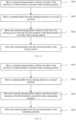
- step S401: moving the material transportation vehicle such that the first position or the third position coincides with the loading position;
- step S402: moving the material pallet from the loading position to the second position;
- step S403: moving the material transportation vehicle to the front of the drying device such that the first position or the third position coincides with the drying station; and
- step S404: moving the material tray from the second position to the drying station.
- In the technical solution of the embodiment of the present application, the material is automatically moved from the loading position to a drying position by means of the material transportation vehicle, achieving the automatic processing of the feeding operation for drying, avoiding manual participation which causes excessive time consumption, and improving the production efficiency.
- In some embodiments, the method for controlling a material drying system further comprises:
- step S501: moving the material transportation vehicle to the front of the drying device such that the first position or the third position coincides with the drying station; and
- step S502: moving the material tray from the drying station to the second position;
- step S503: moving the material transportation vehicle such that the first position or the third position coincides with the unloading position; and
- step S504: moving the material tray from the second position to the unloading position.
- In the technical solution of the embodiments of the present application, the automatic discharging process after drying is achieved by means of the material delivery device, improving the automation degree and transfer speed of material transfer, and improving the production efficiency.
- In some embodiments, the engagement connection between the push-pull assembly and the material pallet is maintained in response to the material pallet being in the second position.
- In the technical solution of the embodiments of the present application, the engagement connection structure between the push-pull assembly and the material pallet can provide a good limiting effect when the material pallet is transported, preventing the material pallet from turning over, and ensuring the smooth and safe transportation.
- In some embodiments, the positioning member on the carrying base is driven to abut against the material pallet or the material contained on the material pallet in response to the material pallet being in the second position.
- In the technical solution of the embodiments of the present application, the positioning member can provide position determination and movement limit functions for the material pallet. Through position determination, it is possible to ensure that the material pallet does not shift or is adjusted in a timely manner after the shift occurs, avoiding apparatus failure caused by overturning during transportation. Moreover, during the transportation, the positioning member can provide contact abutment and limit in the extension direction of the conveying track. This, together with the limit of the push-pull assembly, can achieve limit in two directions in the horizontal plane, better ensuring the stability of transportation.
- In a fifth aspect, an embodiment of the present application provides an electronic apparatus, comprising: at least one processor; and a memory communicatively connected to the at least one processor. The memory stores instructions executable by the at least one processor, and the instructions, when executed by the at least one processor, cause the at least one processor to perform a method for controlling a material drying system in the above embodiments.
- In a sixth aspect, an embodiment of the present application provides a computer-readable storage medium, storing a computer program. When the computer program is executed by a processor, a method for controlling a material drying system in the above embodiments is implemented.
- In a seventh aspect, an embodiment of the present application further provides a computer program product, comprising a computer program. When the computer program is executed by a processor, a method for controlling a material drying system in the above embodiments is implemented.
- The above description is only an overview of the technical solutions of the present application. In order to more clearly understand the technical means of the present application to implement same according to the contents of the description, and in order to make the above and other objectives, features and advantages of the present application more obvious and understandable, detailed description of embodiments of the present application is exemplarily described below.
- In the drawings, the same reference signs denote the same or similar components or elements throughout multiple drawings, unless otherwise specified. The drawings are not necessarily drawn to scale. It should be understood that these drawings depict only some implementations according to the present application and should not be construed as limiting the scope of the present application.
-
FIG. 1 is a schematic diagram of the working of a material transportation vehicle provided in some embodiments of the present application; -
FIG. 2 is a schematic diagram of the working of a material transportation vehicle provided in some other embodiments of the present application; -
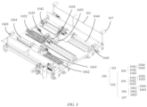
FIG. 3 is a schematic structural diagram of a material transportation vehicle according to some embodiments of the present application; -
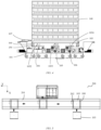
FIG. 4 is a side view of a material transportation vehicle according to some embodiments of the present application; -
FIG. 5 is a structural layout diagram of a material carrying device according to some embodiments of the present application; -
FIG. 6 is a bottom view of a material pallet according to some embodiments of the present application; -
FIG. 7 is a structural layout diagram of a material drying system according to some embodiments of the present application; -
FIG. 8 is a flowchart of a method for controlling a material drying system according to some embodiments of the present application; and -
FIG. 9 is a flowchart of a control method of a material drying system according to some other embodiments of the present application. -
-
material transportation vehicle 100, carryingbase 101, push-pull assembly 102,material pallet 103, engagement block 1031, firstengagement block group 1032, secondengagement block group 1033, thirdengagement block group 1034, first push-pull assembly 104, first push-pull rod 1041, firstlinear driving unit 1042, firstrotary driving unit 1043,first rod body 1044,first engagement portion 1045, second push-pull assembly 105, second push-pull rod 1051, secondlinear driving unit 1052, secondrotary driving unit 1053,second rod body 1054,second engagement portion 1055, third push-pull assembly 106, third push-pull rod 1061, thirdlinear driving unit 1062, thirdrotary driving unit 1063,third rod body 1064,third engagement portion 1065,positioning member 107,first position 110,first transition position 111,second position 120,second transition position 121,third position 130,material 140,first guide member 150,second guide member 160; -
material carrying device 200, conveyingtrack 201, drivingdevice 202; -
material drying system 300, dryingdevice 301, firstvacuum drying furnace 302, secondvacuum drying furnace 303, thirdvacuum drying furnace 304,loading device 305, unloadingdevice 306,loading position 310,first drying position 320,second drying position 330, unloadingposition 340. - Embodiments of the technical solutions of the present application will be described in detail below with reference to the accompanying drawings. The following embodiments are merely intended to more clearly illustrate the technical solutions of the present application, so they merely serve as examples, but are not intended to limit the scope of protection of the present application.
- Unless otherwise defined, all technical and scientific terms used herein have the same meanings as those commonly understood by those skilled in the art to which the present application belongs. The terms used herein are merely for the purpose of describing specific embodiments, but are not intended to limit the present application. The terms "comprising" and "having" and any variations thereof in the description and the claims of the present application as well as the brief description of the accompanying drawings described above are intended to cover non-exclusive inclusion.
- In the description of the embodiments of the present application, the technical terms "first", "second", etc. are merely used for distinguishing different objects, and are not to be construed as indicating or implying relative importance or implicitly indicating the number, particular order or primary-secondary relationship of the indicated technical features. In the description of the embodiments of the present application, the phrase "a plurality of" means two or more, unless otherwise explicitly and specifically defined.
- The phrase "embodiment" mentioned herein means that the specific features, structures, or characteristics described in conjunction with the embodiment can be encompassed in at least one embodiment of the present application. The phrase at various locations in the description does not necessarily refer to the same embodiment, or an independent or alternative embodiment exclusive of another embodiment. Those skilled in the art understand explicitly or implicitly that the embodiment described herein may be combined with another embodiment.
- In the description of the embodiments of the present application, the term "and/or" is merely intended to describe the associated relationship of associated objects, indicating that three relationships can exist, for example, A and/or B may include: only A exists, both A and B exist, and only B exists. In addition, the character "/" herein generally indicates an "or" relationship between the associated objects.
- In the description of the embodiments of the present application, the term "a plurality of" means two or more (including two), similarly the term "a plurality of groups" means two or more groups (including two groups), and the term "a plurality of pieces" means two or more pieces (including two pieces).
- In the description of the embodiments of the present application, the orientation or position relationship indicated by the technical terms "central", "longitudinal", "transverse", "length", "width", "thickness", "upper", "lower", "front", "rear", "left", "right", "vertical", "horizontal", "top", "bottom", "inner", "outer", "clockwise", "counterclockwise", "axial", "radial", "circumferential", etc. are based on the orientation or position relationship shown in the accompanying drawings and are merely intended to facilitate and simplify the description of the embodiments of the present application, rather than indicating or implying that the device or element referred to must have a specific orientation or be constructed and operated in a described orientation, and therefore cannot be construed as limiting the embodiments of the present application.
- In the description of the embodiments of the present application, unless otherwise explicitly specified and defined, the technical terms such as "mounting", "connecting", "connection", and "fixing" should be understood in a broad sense, for example, they may be a fixed connection, a detachable connection, or an integrated connection; may be a mechanical connection or an electric connection; and may be a direct connection or an indirect connection by means of an intermediate medium, or may be internal communication between two elements or interaction between the two elements. For those of ordinary skill in the art, the specific meanings of the above terms in the embodiments of the present application can be understood according to specific situations.
- At present, from the perspective of the development of the market situation, traction batteries are used more and more widely. The traction batteries are not only used in energy storage power systems such as hydroelectric power plants, thermal power plants, wind power plants and solar power plants, but also widely used in electric transportation means such as electric bicycles, electric motorcycles, and electric vehicles and in many fields such as military equipment and aerospace. With the continuous expansion of the application field of traction batteries, market demand for the traction batteries is also expanding.
- The applicant has noticed that as the demand for batteries increases rapidly, the manufacturing capacity of batteries also expands rapidly, and the speed requirements for parts to operate in each procedure are getting higher and higher, thereby putting forward higher automation requirements for the existing production lines and apparatuses.
- In order to improve the operating efficiency for production and manufacturing, the applicant has found that a set of automation devices can be designed to perform automatic transportation and loading and unloading operations on materials, to achieve automated operations in the battery manufacturing process, and reduce manual participation, thereby improving the production efficiency and reducing the manufacturing cost.
- In addition, when a traction battery is in use, moisture will react with an electrolyte during the charging and discharging processes, so that the internal resistance of the battery is increased, and the capacity of the battery, its number of cycles and the electrical performance are reduced, seriously affecting the service life of the battery. Moreover, there are also safety hazards such as explosions. Therefore, moisture content is one of the important factors affecting the quality and performance of traction batteries, and an important means for controlling moisture is the use of a drying procedure. The current drying procedure is still in a semi-automated state, is complex to operate, has many manual participation steps, and takes too long time, significantly hindering the production efficiency and the manufacturing cost.
- Based on the above considerations, in order to solve the problem of low operating efficiency in the battery production process, the applicant has designed a material transportation vehicle after in-depth research, in which a push-pull assembly is arranged on a carrying base to drive a material pallet containing a material to move, so as to implement automatic loading and automatic unloading, so that automatic operations can be achieved during transportation and transfer of the material, improving the production efficiency and reducing the manufacturing cost.
- The material transportation vehicle disclosed in the embodiments of the present application may be, but not limited to, a rail guided vehicle (RGV), a transport robot, etc. The material transportation vehicle may be used for, but not limited to, transportation and drying operations of battery cells, battery electrode plates, and battery modules. The material transportation vehicle disclosed in the present application may be used to form a material carrying device, a material drying system, and a method for controlling a material drying system, etc. This helps to reduce the transportation time, improve the battery production efficiency, and reduce the manufacturing cost.
- Referring to
FIG. 1, FIG. 1 is a schematic diagram of the working of a material transportation vehicle provided in some embodiments of the present application.FIG. 1(a) shows a material pallet in a first position,FIG. 1(b) shows the material pallet in a first transition position, andFIG. 1(c) shows the material pallet in a second position. - According to some embodiments of the present application, the
material transportation vehicle 100 comprises a carryingbase 101 and a push-pull assembly 102 arranged on the carrying base. The push-pull assembly 102 is configured to drive thematerial pallet 103 to move between afirst position 110 and asecond position 120. Thesecond position 120 is located above the carryingbase 101, and thefirst position 110 is located in the same horizontal plane as thesecond position 120 and separated from thesecond position 120 by a preset distance in a first direction X. - Illustratively, the
material pallet 103 may be configured to contain a material. The material may be a workpiece or module to be transported or processed, such as a battery cell. Thematerial pallet 103 may contain a plurality of workpieces or modules at the same time. The plurality of workpieces or modules may be placed in a suitable manner and arranged according to the placement requirements during machining or processing. For example, the plurality of battery cells may be stacked on thematerial pallet 103. Thesecond position 120 may be a position directly above the carryingbase 101. Thefirst position 110 is a position in the same horizontal plane as thesecond position 120 and separated by a preset distance in the first direction X. It can be understood that, as shown inFIG. 1 , thefirst position 110 is a position that is staggered and separated by a certain distance from thesecond position 120 in the first direction X, and is located outside thematerial transportation vehicle 100. When thematerial transportation vehicle 100 moves, the absolute spatial positions of thefirst position 110 and thesecond position 120 will also change accordingly. Moreover, the preset distance between thefirst position 110 and thesecond position 120 may also be set based on the actual usage scenario, so that driving thematerial pallet 103 to move between thefirst position 110 and thesecond position 120 can realize the movement of thematerial pallet 103 into and out of the carryingbase 101 of thematerial transportation vehicle 100. The first direction X may be set according to the requirements of the specific movement direction. - In this embodiment, a push-
pull assembly 102 capable of driving the movement of thematerial pallet 103 is arranged on the carryingbase 101, so that thematerial pallet 103 can automatically move into and out of the carryingbase 101, thereby achieving automatic handling of material transportation without manual participation, improving the production efficiency, and reducing the manufacturing cost. - According to some embodiments of the present application, as shown in
FIG. 1 , the push-pull assembly 102 comprises a first push-pull assembly 104 and a second push-pull assembly 105 arranged spaced apart from each other. The first push-pull assembly 104 is configured to be detachably connected to thematerial pallet 103 and drive thematerial pallet 103 to move between thefirst position 110 and afirst transition position 111. The second push-pull assembly 105 is configured to be detachably connected to thematerial pallet 103 and drive thematerial pallet 103 to move between thesecond position 120 and thefirst transition position 111. Thefirst transition position 111 is located between thefirst position 110 and thesecond position 120. - It can be understood that, as shown in
FIG. 1 , thefirst transition position 111, thefirst position 110 and thesecond position 120 are positions located in the same horizontal plane and staggered in the same direction, for example, arranged in sequence in the first direction X. The push-pull assembly 102 drives thematerial pallet 103 to move from thefirst position 110 to thesecond position 120 in two steps. The first step is for the first push-pull assembly 104 to drive thematerial pallet 103 to move from thefirst position 110 to thefirst transition position 111, and then the second push-pull assembly 105 drives thematerial pallet 103 to move from thefirst transition position 111 to thesecond position 120, that is, above the carryingbase 101, so as to complete the process of moving thematerial pallet 103 into the carryingbase 101. Conversely, the process of moving thematerial pallet 103 out of the carryingbase 101 is to move the material pallet from thesecond position 120 to thefirst transition position 111, and then move the material pallet from thefirst transition position 111 to thefirst position 110, so as to completely separate thematerial pallet 103 from thematerial transportation vehicle 100. - In the embodiments of the present application, by providing the first push-
pull assembly 104 and the second push-pull assembly 105 to move thematerial pallet 103 in a two-stage driving manner, the problem of insufficient stability of a single-stage driving structure can be avoided, and the movement range of the push-pull assembly can be reduced, so that the structural stress is more reasonable. -
FIGS. 2(a)-(c) show schematic diagrams of the movement process of a material transportation vehicle driving a material pallet provided in some other embodiments of the present application.FIG. 2(a) shows the material pallet in the second position,FIG. 1(b) shows the material pallet in the second transition position, andFIG. 1 (c) shows the material pallet in a third position. - In some embodiments, as shown in
FIG. 2 , the push-pull assembly 102 is further configured to drive thematerial pallet 103 to move between thesecond position 120 and thethird position 130. Thethird position 130 and thesecond position 120 are located in the same horizontal plane, and the third position and thefirst position 110 are respectively located on two sides of thesecond position 120 in the first direction X. - It can be understood that the
material pallet 103 may be driven by the push-pull assembly 102 to move to two sides in the same direction or in opposite directions with respect to the first direction X, so that on either side of the carryingbase 101 in the first direction X, thematerial pallet 103 can be moved in and out. That is, the material pallet may be moved in and out on the same side, or may be moved in on one side and out on the other side. - In the technical solution of the embodiments of the present application, the push-
pull assembly 102 drives thematerial pallet 103 to move to two sides of thesecond position 120, so it is possible to get rid of the restriction of the specific orientation when a station is arranged, and to improve the applicable scope and the delivery efficiency of the device. In particular, based on the two-stage push-pull mode shown in the embodiments of the present application, the stress problem caused by an excessively long single-stage push-pull stroke can be well avoided. When moving in two directions, the push-pull stroke of each stage does not need to deviate too far from the carrying base, so there is no need to change the track configuration and the structural layout, but only need to make simple adjustments to the driving unit. This will not be constrained by the structural layout, the application scenarios can be expanded, and the operating efficiency of the device can be improved. - In some embodiments, as shown in
FIG. 2 , the first push-pull assembly 104 comprises a first push-pull rod 1041, a firstlinear driving unit 1042 and a firstrotary driving unit 1043. The first push-pull rod 1041 comprises afirst rod body 1044 and afirst engagement portion 1045 fixedly connected to thefirst rod body 1044. The firstlinear driving unit 1042 is in transmission connection with thefirst rod body 1044 to drive the first push-pull rod 1041 to move between thefirst position 110 and thefirst transition position 111. The firstrotary driving unit 1043 is in transmission connection with thefirst rod body 1044, and the firstrotary driving unit 1043 drives thefirst engagement portion 1045 to rotate, such that thefirst engagement portion 1045 engages with or disengages from thematerial pallet 103. - The second push-
pull assembly 105 comprises a second push-pull rod 1051, a secondlinear driving unit 1052 and a secondrotary driving unit 1053. The second push-pull rod 1051 comprises asecond rod body 1054 and at least onesecond engagement portion 1055 fixedly connected to thesecond rod body 1054. The secondlinear driving unit 1052 is in transmission connection with thesecond rod body 1054 to drive the second push-pull rod 1051 to move between thesecond position 120 and thefirst transition position 111. The secondrotary driving unit 1053 is in transmission connection with thesecond rod body 1054, and the secondrotary driving unit 1053 drives the at least onesecond engagement portion 1055 to rotate, such that the at least onesecond engagement portion 1055 engages with or disengages from thematerial pallet 103. - In an example, as shown in
FIG. 2 , the first push-pull rod 1041 moves linearly in the first direction X under the driving of the firstlinear driving unit 1042. After reaching a designated position, the first push-pull rod 1041 is driven by the firstrotary driving unit 1043 to rotate, such that thefirst engagement portion 1045 engages with or disengages from thematerial pallet 103 through rotation, thereby achieving the detachable connection. Similarly, the second push-pull rod 1051 also works on the same principle. The firstlinear driving unit 1042 and the secondlinear driving unit 1052 may be an electric motor and lead screw drive, or may be a telescopic cylinder drive. The firstlinear driving unit 1042 and the secondlinear driving unit 1052 may be the same or different. The firstrotary driving unit 1043 and the secondrotary driving unit 1053 may be an electric motor that transmits rotation through a belt or an electric motor that transmits rotation through gears. The firstrotary driving unit 1043 and the secondrotary driving unit 1053 may be the same or different. - In the technical solution of the embodiments of the present application, the first push-
pull assembly 104 and the second push-pull assembly 105 are respectively provided with thefirst engagement portion 1045 and thesecond engagement portion 1055 to engage with or disengage from thematerial pallet 103 to achieve detachable connection, and in combination with the cooperation of the linear driving units and the rotary driving units, the first push-pull assembly 104 and the second push-pull assembly 105 can respectively engage with thematerial pallet 103 and then push and pull the material pallet to move, thereby achieving two-stage driving, reducing the driving stroke of each stage, avoiding damage to the structure due to large stress and deformation caused by excessive distance during single-stage push and pull, and improving the structural stability and the safety of the device. - In some embodiments, as shown in
FIGS. 2 and3 , the push-pull assembly 102 further comprises a third push-pull assembly 106. The third push-pull assembly 106 is arranged on the carryingbase 101 and spaced apart from the first push-pull assembly 104 and the second push-pull assembly 105. The second push-pull assembly 105 is further configured to drive thematerial pallet 103 to move between thesecond position 120 and asecond transition position 121. The third push-pull assembly 106 is further configured to drive thematerial pallet 103 to move between thesecond transition position 121 and thethird position 120. Thesecond transition position 121 is located between thesecond position 120 and thethird position 130. - In the technical solution of the embodiments of the present application, the bidirectional movement of the
material pallet 103 is achieved by providing the third push-pull assembly 106, so that the second push-pull assembly 105 can cooperate with the first push-pull assembly 104 and the third push-pull assembly 106 respectively such that thematerial pallet 103 can be moved in a two-stage driving manner on two sides, thereby improving the utilization efficiency of the second push-pull assembly 105, avoiding redundancy in structural design, improving the utilization rate of the device, and improving the operating efficiency. - In some embodiments, as shown in
FIG. 3 , the third push-pull assembly 106 comprises a third push-pull rod 1061, a thirdlinear driving unit 1062 and a thirdrotary driving unit 1063. The third push-pull rod 1061 comprises athird rod body 1064 and athird engagement portion 1065 fixedly connected to thethird rod body 1064. The thirdlinear driving unit 1062 is in transmission connection with thethird rod body 1064, and the thirdlinear driving unit 1062 is configured to drive the third push-pull rod 1061 to move between thethird position 130 and thesecond transition position 121. The thirdrotary driving unit 1063 is in transmission connection with thethird rod body 1064, and the thirdrotary driving unit 1063 is configured to drive thethird engagement portion 1065 to rotate, such that thethird engagement portion 1065 engages with or disengages from thematerial pallet 103. - In an example, the
third engagement portion 1065 may have the same size as thefirst engagement portion 1045 and the secondengagement portion structure 1055. The thirdlinear driving unit 1062 and the thirdrotary driving unit 1063 may also be respectively configured to be consistent with the firstlinear driving unit 1042 and the secondlinear driving unit 1052, and thefirst rotary drive 1043 and the secondrotary driving unit 1053, to improve the consistency of parts and facilitate subsequent maintenance. - In the technical solution of the embodiments of the present application, the structure of the third push-
pull assembly 106 being consistent with that of the first push-pull assembly 104 and that of the second push-pull assembly 105 can simplify the types of parts and facilitate subsequent maintenance, while maintaining the consistency of the movement structures on two sides, thereby avoiding the imbalance caused by a large difference in stress between the driving structures on the two sides. - In some embodiments, the
first position 110 and thethird position 130 are mirror symmetrical with respect to thesecond position 120, and thefirst transition position 111 and thesecond transition position 121 are mirror symmetrical with respect to thesecond position 120. - In the technical solution of the embodiments of the present application, specifically arranging the
first position 110 and thethird position 130, and thefirst transition position 111 and thesecond transition position 121 to be mirror symmetrical can more easily achieve positioning when moving between different sides, simplify the control logic of the driving units, and reduce the failure rate. - In some embodiments, as shown in
FIG. 4 , thematerial transportation vehicle 100 further comprises apositioning member 107 fixedly connected to the carryingbase 101 and configured to abut against thematerial pallet 103 or amaterial 140 contained on thematerial pallet 103 in response to thematerial pallet 103 being in thesecond position 120. - In an example, the positioning
member 107 may be a positioning cylinder. After thematerial pallet 103 is moved into the carryingbase 101, a piston rod of the positioning cylinder is driven to move and abut against the material pallet for positioning. For example, the arrangement direction of thepositioning member 107 may be different from the first direction X to provide limit in a different direction, for example, perpendicular to the first direction. It can be understood that materials contained on thematerial pallet 103 may be placed in a stacked manner, such as stacked battery cells. - In the technical solution of the embodiments of the present application, by providing the
positioning member 107 to limit thematerial pallet 103 or the material on thematerial pallet 103, the stability during transportation can be ensured and overturning can be avoided. Moreover, the positioning function of thepositioning member 107 can also be used to determine whether the position of thematerial pallet 103 is in place. If the position of thematerial pallet 103 is somewhat offset from thesecond position 120, the positioningmember 107 will send out an alarm signal because it cannot reach a preset positioning position, to remind an operator to adjust the position of the material pallet to avoid accidents during the transportation and ensure the transportation safety. - In a second aspect, an embodiment of the present application provides a material carrying device. As shown in
FIG. 5 , thematerial carrying device 200 comprises: amaterial pallet 103 configured to contain a material, a conveyingtrack 201, and amaterial transportation vehicle 100. Thematerial transportation vehicle 100 may be the material transportation vehicle in any of the above embodiments. - In an example, the
material transportation vehicle 100 may be an RGV, and the conveyingtrack 201 may be an RGV track. Thematerial carrying device 200 may cooperate with any processing apparatus to achieve automatic operation of one or more processing procedures of the material. Specifically, thematerial carrying device 200 transports thematerial pallet 103 containing the material from a loading place to the processing apparatus for processing. After the processing procedure is completed, thematerial pallet 103 containing the material is moved from the processing apparatus to a discharging place. The processing apparatus includes a vacuum drying furnace, a reaction furnace, etc. - In the technical solution of the embodiments of the present application, through the cooperation of the
material transportation vehicle 100 and the conveyingtrack 201, long-distance transportation can be achieved, so that the transportation vehicle in thematerial carrying device 200 can achieve the transfer of the material between different positions. Combined with processing apparatuses for different procedures, the automatic loading, unloading and transportation of the material in different processing procedures can be achieved to improve the operating efficiency for production. - In some embodiments, as shown in
FIGS. 4-5 , an upper surface of the carryingbase 101 is provided with at least onefirst guide member 150 extending in the first direction X, and a bottom portion of thematerial pallet 103 is provided with at least onesecond guide member 160 corresponding to the at least onefirst guide member 150. The first direction X is perpendicular to an extension direction Y of the conveyingtrack 201. - It can be understood that the first direction X and the extension direction Y of the conveying
track 201 are located in the same horizontal plane and are perpendicular to each other. The first direction X is the arrangement direction of thefirst position 110, thesecond position 120 and thethird position 130, and is also the movement direction of thematerial pallet 103. In an example, as shown inFIG. 4 , thefirst guide member 150 may be a slide rail, and the correspondingsecond guide member 160 may be a slide groove to cooperate with the slide rail to provide guidance and limit for the movement of thematerial pallet 103. In some other embodiments, thefirst guide member 150 may alternatively be a slide groove, and the correspondingsecond guide member 160 may be a slide rail or a pulley. The number offirst guide members 150 and the number ofsecond guide members 160 may be two, or may be one or three or more. - In the technical solution of the embodiments of the present application, the corresponding arrangement of the
first guide member 150 and thesecond guide member 160 can provide a guidance for thematerial pallet 103 during moving, to avoid deviation. Still further, thefirst guide member 150 and thesecond guide member 160 can also provide support in the vertical direction, so as to, when thematerial pallet 103 moves, prevent all or part of the gravity from acting on the push-pull assembly, which causes the push-pull assembly to be deformed and damaged due to excessive force, thereby improving the structural reliability and stability of the device. Setting the first direction X perpendicular to the extension direction Y of the track facilitates the arrangement of the moving space of thematerial pallet 103 to avoid interference with other apparatuses, and also facilitates the control over the moving strokes of the loading and unloading of the material. - In some embodiments, as shown in
FIG. 6 , the bottom portion of thematerial pallet 103 is provided with an engagement block 1031, and the engagement block 1031 cooperates with the push-pull assembly 102 to achieve a detachable connection between thematerial pallet 103 and thematerial transportation vehicle 100. - Illustratively, the engagement block 1031 may be a bump extending outwardly along a bottom surface of the material pallet, and there may be a plurality of engagement blocks. As shown in
FIG. 6 , the engagement blocks 1031 comprise a firstengagement block group 1032 which cooperates with thefirst engagement portion 1045, a secondengagement block group 1033 which cooperates with thesecond engagement portion 1055, and a thirdengagement block group 1034 which cooperates with thethird engagement portion 1065. There may be one or more engagement blocks in the firstengagement block group 1032, the secondengagement block group 1033 and the thirdengagement block group 1034. - It can be understood that the engagement blocks 1031 cooperate with the
first engagement portion 1045, thesecond engagement portion 1055 and thethird engagement portion 1065 in the push-pull assembly 102. Thefirst engagement portion 1045, thesecond engagement portion 1055 and thethird engagement portion 1065 may be provided with engagement grooves that are adapted to the size of the engagement blocks 1031, so as to achieve the detachable connection between thematerial pallet 103 and thematerial transportation vehicle 100. - In the technical solution of the embodiments of the present application, the detachable connection between the
material pallet 103 and thematerial transportation vehicle 100 is achieved in an engagement manner by providing the engagement block 1031 which cooperates with the push-pull assembly 102, so that the push-pull assembly 102 can drive the material pallet through mutually independent multi-stage push-pull movements, to avoid excessive load caused by a too long push-pull stroke. - In some embodiments, the
material carrying device 200 further comprises adriving device 202. Thedriving device 202 is configured to drive thematerial transportation vehicle 100 to move along the conveyingtrack 201. As shown inFIG. 4 , the drivingdevice 202 is arranged at one end of the carrying base of thematerial transportation vehicle 100. - It can be understood that the
driving device 202 can be arranged either on thematerial transportation vehicle 100, or at one end of the conveyingtrack 201, and is in transmission connection with thematerial transportation vehicle 100 via a transmission structure. - In the technical solution of the embodiments of the present application, the autonomous movement of the material transportation vehicle can be achieved by means of the
driving device 202, thereby achieving the automatic transportation of the material, and improving the transfer efficiency of the material between different procedures. - In a third aspect, an embodiment of the present application provides a material drying system. As shown in
FIG. 7 , thematerial drying system 300 comprises amaterial carrying device 200, and adrying device 301 located on a side of a conveyingtrack 201 in thematerial carrying device 200. Thematerial carrying device 200 is configured to move thematerial pallet 103 into or out of a drying station in thedrying device 301. Thematerial carrying device 200 is the material carrying device in the above embodiments. - In an example, the
material transportation vehicle 100 in thematerial carrying device 200 delivers thematerial pallet 103 to an inlet of thedrying device 301, and under the driving of the push-pull assembly 102, thematerial pallet 103 is moved from thesecond position 120 on the carryingbase 101 to the drying station in thedrying device 301. After the drying is completed, thematerial pallet 103 is moved out of the drying station by the push-pull assembly 102 again to thesecond position 120 on the carryingbase 101, and is then transferred away. - In the technical solution of the embodiments of the present application, by arranging the drying device on the side of the conveying track of the material carrying device, automatic feeding and automatic discharging during drying operation can be achieved; thereby avoiding manual participation and improving the operating efficiency and the safety.
- In some embodiments, as shown in
FIG. 7 , thedrying device 301 is configured as a plurality of vacuum drying furnaces arranged on one side or two sides of the conveyingtrack 201. - It can be understood that, as shown in
FIG. 7 , the plurality of vacuum drying furnaces may be arranged on the same side of the conveying track, or may be respectively located on two sides of the conveying track. In an example, thedrying device 301 comprises a firstvacuum drying furnace 302, a secondvacuum drying furnace 303, and a thirdvacuum drying furnace 304. The firstvacuum drying furnace 302 and the secondvacuum drying furnace 303 are located on the same side of the conveyingtrack 201, and the thirdvacuum drying furnace 304 is located on the other side of the conveyingtrack 201. - In the technical solution of the embodiments of the present application, the provision of the plurality of vacuum drying furnaces can make full use of the efficient conveying capability of the
material carrying device 200. The vacuum drying furnaces are arranged on two sides of the conveyingtrack 201 and thematerial carrying device 200 can drive thematerial pallet 103 to the two sides, so that the station layout of the conveying system is facilitated, the compactness of thematerial drying system 300 is improved, the footprint is reduced, and the operating efficiency of the material drying process is improved, thereby improving the production efficiency and reducing the manufacturing cost. - In some embodiments, the
material drying system 300 further comprises aloading device 305 and anunloading device 306. The loading device is located at one end of the conveyingtrack 201 and is configured to place a material in astacked manner 140 on thematerial pallet 103 in aloading position 310. Theunloading device 306 is located at the other end of the conveyingtrack 201, and is configured to take the material away from thematerial pallet 103 in anunloading position 340. - In an example, the
loading device 305 and theunloading device 306 may be manipulators. The manipulator grabs a material, such as a battery cell, and places the material on thematerial pallet 103 in the loading position or removes the material from thematerial pallet 103 in the unloading position. Theloading position 310 refers to a position where thematerial pallet 103 is prepared to be transferred to thematerial transportation vehicle 100, and theunloading position 340 refers to a position where thematerial pallet 103 is placed after being moved out of thematerial transportation vehicle 100. - In the technical solution of the embodiments of the present application, by providing the
loading device 305 and theunloading device 306 respectively at two ends of the conveyingtrack 201, the automatic operations of loading and unloading are achieved, forming a fully automated operation process, shortening the conversion time between different procedures, and improving the production efficiency. - In a fourth aspect, an embodiment of the present application provides a method for controlling a material drying system. As shown in
FIG. 8 , the method for controlling a material drying system comprises: - step S401: moving a
material transportation vehicle 100 such that afirst position 110 or athird position 130 coincides with aloading position 310; - step S402: moving a
material pallet 103 from theloading position 310 to asecond position 120; - step S403: moving the
material transportation vehicle 100 to the front of adrying device 301 such that thefirst position 110 or thethird position 130 coincides with a dryingstation 320; and - step S404: moving the
material tray 103 from thesecond position 120 to the dryingstation 320. - In an example, the method for controlling a material drying system comprises delivering the material pallet from the loading position to the drying station in the drying device to perform a drying operation. As shown in
FIG. 7 , thematerial transportation vehicle 100 is moved to the front of theloading position 310, until the first position or the third position corresponding to the second position on the carrying base of thematerial transportation vehicle 100 in the first direction X coincides with theloading position 310, such that the push-pull assembly 102 can be detachably connected to thematerial pallet 103 to drive thematerial pallet 103 to move from theloading position 310 to thesecond position 120 on the carryingbase 101 of thematerial transportation vehicle 100. Thematerial transportation vehicle 100 is moved to the front of the inlet of the firstvacuum drying furnace 302, until thefirst position 110 or thethird position 130 corresponding to the material transportation vehicle coincides with the dryingstation 320 in the firstvacuum drying furnace 302, such that the push-pull assembly 102 can move thematerial pallet 103 from thesecond position 120 on the carryingbase 101 to the dryingstation 320 in the firstvacuum drying furnace 302, completing the automatic delivery process of delivering the material from theloading position 310 to the dryingstation 320. - It can be understood that the relative positioning of the material transportation vehicle with respect to the loading position and the drying station can be achieved by providing a positioning structure or by sensor positioning, so as to ensure that the material pallet is moved to a predetermined position in a predetermined direction.
- In the technical solution of the embodiment of the present application, the material is automatically moved from the loading position to the drying position by means of the material transportation vehicle, achieving the automatic processing of the feeding operation for drying, avoiding manual participation which causes excessive time consumption, and improving the production efficiency.
- In some embodiments, as shown in
FIG. 9 , the method for controlling a material drying system further comprises: - step S501: moving the
material transportation vehicle 100 to the front of thedrying device 301 such that thefirst position 110 or thethird position 130 coincides with the drying station; - step S502: moving the
material tray 103 from the drying station to thesecond position 120; - step S503: moving the
material transportation vehicle 100 such that thefirst position 110 or thethird position 130 coincides with anunloading position 340; and - step S504: moving the
material tray 103 from thesecond position 120 to theunloading position 340. - In an example, the method for controlling a material drying system further comprises a discharging process of moving the material pallet out from a drying position in the drying device and delivering the material pallet to the unloading position. As shown in
FIG. 7 , thematerial transportation vehicle 100 is moved to the front of the thirdvacuum drying furnace 304 in thedrying device 301 until thefirst position 110 or thethird position 130 corresponding to the carryingbase 101 coincides with asecond drying position 330. The push-pull assembly 102 drives thematerial pallet 103 to move from thesecond drying position 330 to thesecond position 120 on the carryingbase 101, and then is delivered by the movingmaterial transportation vehicle 100 to one end of the conveyingtrack 202 to facilitate unloading of the material. Specifically, thematerial transportation vehicle 100 needs to move to the place where thefirst position 110 or thethird position 130 coincides with theunloading position 340, and then the push-pull assembly 102 drives thematerial pallet 103 to move from thesecond position 120 to theunloading position 340. It can be understood that thematerial transportation vehicle 100 may be configured to drive thematerial pallet 103 to always move on the same side of the carryingbase 101, that is, theloading position 310, the drying position and theunloading position 340 are all located on the same side of the material transportation vehicle. Alternatively, the material transportation vehicle may be configured to drive the material pallet to move along two sides of the first direction of the carrying base, that is, the loading position, the drying position and the unloading position may be arbitrarily distributed on the two sides of the carrying base. - In the technical solution of the embodiments of the present application, the automatic discharging process after drying is achieved by means of the material delivery device, improving the automation degree and transfer speed of material transfer, and improving the production efficiency.
- In some embodiments, the engagement connection between the push-
pull assembly 102 and thematerial pallet 103 is maintained in response to thematerial pallet 103 being in thesecond position 120. - In an example, as shown in
FIGS. 3 and4 , the second push-pull assembly 105 in the push-pull assembly 102 is provided with two secondsecond engagement portions 1055. When thematerial pallet 103 is located in the second position on the carryingbase 101, by maintaining the engagement relationship between thesecond engagement portions 1055 and the secondengagement block group 1033 of the bottom portion of thematerial pallet 103, the push-pull assembly 102 can limit thematerial pallet 103 when thematerial transportation vehicle 100 moves with thematerial pallet 103, to ensure the stability during transportation. Since the movements of each push-pull rod and each engagement portion in the push-pull assembly 102 are independent, the first push-pull assembly 104 and the third push-pull assembly 106 in the push-pull assembly 102 may also maintain an engagement connection with their corresponding engagement blocks when thematerial pallet 103 is located in the second position on the carryingbase 101. - In the technical solution of the embodiments of the present application, the engagement connection structure between the push-pull assembly and the material pallet can provide a good limiting effect when the material pallet is transported, preventing the material pallet from turning over, and ensuring the smooth and safe transportation.
- In some embodiments, the positioning member on the carrying base is driven to abut against the material pallet or the material contained on the material pallet in response to the material pallet being in the second position.
- In an example, as shown in
FIG. 4 , after thematerial pallet 103 is moved to thesecond position 120, the positioningmember 107 may be driven to abut against thematerial pallet 103 or thematerial 140 in the extension direction of the conveying track. In this case, if the position of the material pallet deviates from the preset second position, the positioningmember 107 cannot meet the preset abutment requirements, thereby sending an alarm signal to remind the operator to adjust the position of the material pallet. - In the technical solution of the embodiments of the present application, the positioning member can provide position determination and movement limit functions for the material pallet. Through position determination, it is possible to ensure that the material pallet does not shift or is adjusted in a timely manner after the shift occurs, avoiding apparatus failure caused by overturning during transportation. Moreover, during the transportation, the positioning member can provide contact abutment and limit in the extension direction of the conveying track. This, together with the limit of the push-pull assembly, can achieve limit in two directions in the horizontal plane, better ensuring the stability of transportation.
- In a fifth aspect, an embodiment of the present application provides an electronic apparatus, comprising: at least one processor; and a memory communicatively connected to the at least one processor. The memory stores instructions executable by the at least one processor, and the instructions, when executed by the at least one processor, cause the at least one processor to perform a method for controlling a material drying system in the above embodiments.
- In a sixth aspect, an embodiment of the present application provides a computer-readable storage medium, storing a computer program. When the computer program is executed by a processor, a method for controlling a material drying system in the above embodiments is implemented.
- In a seventh aspect, an embodiment of the present application further provides a computer program product, comprising a computer program. When the computer program is executed by a processor, a method for controlling a material drying system in the above embodiments is implemented.
- In an example, the
material drying system 300 shown inFIGS. 2-7 comprises amaterial carrying device 200, adrying device 301, aloading device 305 and anunloading device 306. - The material carrying device comprises a conveying
track 201, amaterial transportation vehicle 100 arranged on the conveyingtrack 201, adriving device 202, and amaterial pallet 103 configured to contain a material. The conveyingtrack 201 is arranged in a straight line, and thedriving device 202 is arranged on thematerial transportation vehicle 100 to drive thematerial transportation vehicle 100 to move on the conveyingtrack 201. - The
drying device 301 comprises a firstvacuum drying furnace 302 and a secondvacuum drying furnace 303 located on one side of the conveyingtrack 201, and a thirdvacuum drying furnace 304 located on the other side of the conveyingtrack 201. - The
loading device 305 is located at a first end of the conveyingtrack 201, and theunloading device 306 is located at a second end of the conveyingtrack 201. - The feeding process of the
material drying system 300 is as follows. - The
loading device 305 grabs a battery cell delivered by a feeding belt and places the battery cell in a stacked manner on thematerial pallet 103. - The
driving device 202 drives thematerial transportation vehicle 100 to move to the first end of the conveyingtrack 201 until the first position corresponding to the carryingbase 101 of thematerial transportation vehicle 100 coincides with theloading position 310. - The first
linear driving unit 1042 drives the first push-pull rod 1041 to move to the first position until thefirst engagement portion 1045 moves to the position where the firstengagement block group 1032 is located. The firstrotary driving unit 1043 drives the first push-pull rod 1041 to rotate, so as to engage the engagement groove on thefirst engagement portion 1045 with the firstengagement block group 1032. The firstlinear driving unit 1042 drives the first push-pull rod 1041 to drive thematerial pallet 103 to move to thefirst transition position 111, and the firstrotary driving unit 1043 drives the first push-pull rod 1041 to rotate to disengage thefirst engagement portion 1045 from the first engagement block group, thereby completing the first push-pull stage. - The second
linear driving unit 1052 drives the second push-pull rod 1051 to move until thesecond engagement portion 1055 moves to the position where the secondengagement block group 1033 is located, and the secondrotary driving unit 1053 drives the second push-pull rod 1051 to rotate, so as to engage thesecond engagement portion 1055 with the secondengagement block group 1033. The secondlinear driving unit 1052 drives the second push-pull rod 1051 to drive thematerial pallet 103 to move from thefirst transition position 111 to thesecond position 120, completing the second push-pull stage. - The positioning
member 107 is driven to abut against the side of thematerial pallet 103, so as to provide limit and support for thematerial pallet 103 in the extension direction Y of the track. - The
driving device 202 drives thematerial transportation vehicle 100 to move along the conveyingtrack 201 to the front of the firstvacuum drying furnace 302, and thematerial transportation vehicle 100 moves along the conveyingtrack 201 to maintain the engagement connection between thesecond engagement portion 1055 and the secondengagement block group 1033. When thethird position 130 coincides with thefirst drying position 320 in the firstvacuum drying furnace 302, thematerial transportation vehicle 100 stops moving, and thepositioning member 107 is separated from thematerial pallet 103 to cancel the limit. - The second
linear driving unit 1052 drives the second push-pull rod 1051 to drive thematerial pallet 103 to move from thesecond position 120 to thesecond transition position 121, and the secondrotary driving unit 1053 drives the second push-pull rod 1051 to rotate to disengage thesecond engagement portion 1055 from the secondengagement block group 1033. - The third
linear driving unit 1062 drives the third push-pull rod 1061 to move to the position where thethird engagement portion 1065 corresponds to the thirdengagement block group 1034, the thirdrotary driving unit 1063 drives the third push-pull rod 1061 to rotate to engage thethird engagement portion 1065 with the thirdengagement block group 1034, the thirdlinear driving unit 1062 drives the third push-pull rod 1061 to drive thematerial pallet 103 to move from thesecond transition position 121 to thefirst drying position 320 in the firstvacuum drying furnace 302, the thirdrotary driving unit 1063 drives the third push-pull rod 1061 to rotate to disengage thethird engagement portion 1065 from the thirdengagement block group 1034, the thirdlinear driving unit 1062 drives the third push-pull rod 1061 to return to the second position, and a furnace door of the firstvacuum drying furnace 302 is closed, completing the feeding process of the material drying operation. - The discharging process of the
material drying system 300 is as follows. - The
driving device 202 moves thematerial transportation vehicle 100 to the front of the thirdvacuum drying furnace 304 until thefirst position 110 coincides with thesecond drying position 330 in the thirdvacuum drying furnace 304. - The push-
pull assembly 102 drives thematerial pallet 103 to move from thesecond drying position 330 in the thirdvacuum drying furnace 304 to thesecond position 120, completing the movement of the material out of the thirdvacuum drying furnace 304. This process is substantially the same as the movement from theloading position 310 to thesecond position 120 in the feeding process. The positioningmember 107 abuts against a side surface of thematerial pallet 103. - The engagement state of the
second engagement portion 1055 and the secondengagement block group 1033 is maintained, and thedriving device 202 moves thematerial transportation vehicle 100 to the front of theunloading position 340 until thefirst position 110 coincides with theunloading position 340. Thematerial transportation vehicle 100 stops moving, and thepositioning member 107 releases the abutment against thematerial pallet 103. - The push-
pull assembly 102 drives thematerial pallet 103 to move from thesecond position 120 to theunloading position 340. This process is substantially the same as the movement from thesecond position 120 to thefirst drying position 320 in the feeding process. - The
unloading device 306 grabs the battery cell from thematerial pallet 103 in theunloading position 340 and transfers it to an unloading belt for removal, completing the entire discharging process. - Finally, it should be noted that the above embodiments are merely used for illustrating rather than limiting the technical solutions of the present application. Although the present application has been illustrated in detail with reference to the foregoing embodiments, it should be understood by those of ordinary skill in the art that the technical solutions described in the foregoing embodiments may still be modified, or some or all of the technical features thereof may be equivalently substituted; and such modifications or substitutions do not make the essence of the corresponding technical solution depart from the scope of the technical solutions of the embodiments of the present application, and should fall within the scope of the claims and the description of the present application. In particular, the technical features mentioned in the embodiments can be combined in any manner, provided that there is no structural conflict. The present application is not limited to the specific embodiments disclosed herein but includes all the technical solutions that fall within the scope of the claims.
Claims (22)
- A material transportation vehicle, comprising:a carrying base, anda push-pull assembly arranged on the carrying base,wherein the push-pull assembly is configured to drive a material pallet to move between a first position and a second position; and the second position is a position above the carrying base, and the first position is a position located in the same horizontal plane as the second position and separated from the second position by a preset distance in a first direction.
- The material transportation vehicle according to claim 1, wherein the push-pull assembly comprises:a first push-pull assembly configured to be detachably connected to the material pallet and drive the material pallet to move between the first position and a first transition position; anda second push-pull assembly arranged spaced apart from the first push-pull assembly, the second push-pull assembly being configured to be detachably connected to the material pallet and drive the material pallet to move between the second position and the first transition position,wherein the first transition position is located between the first position and the second position.
- The material transportation vehicle according to claim 2, wherein the push-pull assembly is further configured to drive the material pallet to move between the second position and a third position;
wherein the third position and the second position are located in the same horizontal plane, and the third position and the first position are respectively located on two sides of the second position in the first direction. - The material transportation vehicle according to claim 2, wherein
the first push-pull assembly comprises:a first push-pull rod, comprising a first rod body and a first engagement portion fixedly connected to the first rod body;a first linear driving unit, which is in transmission connection with the first rod body to drive the first push-pull rod to move between the first position and the first transition position; anda first rotary driving unit, which is in transmission connection with the first rod body, the first rotary driving unit driving the first engagement portion to rotate, such that the first engagement portion engages with or disengages from the material pallet; andthe second push-pull assembly comprises:a second push-pull rod, comprising a second rod body and at least one second engagement portion fixedly connected to the second rod body;a second linear driving unit, which is in transmission connection with the second rod body to drive the second push-pull rod to move between the second position and the first transition position; anda second rotary driving unit, which is in transmission connection with the second rod body, the second rotary driving unit driving the at least one second engagement portion to rotate, such that the at least one second engagement portion engages with or disengages from the material pallet. - The material transportation vehicle according to claim 3, wherein the push-pull assembly further comprises:a third push-pull assembly arranged on the carrying base and spaced apart from the first push-pull assembly and the second push-pull assembly;wherein the second push-pull assembly is further configured to drive the material pallet to move between the second position and a second transition position;wherein the third push-pull assembly is further configured to drive the material pallet to move between the second transition position and the third position; andthe second transition position is between the second position and the third position.
- The material transportation vehicle according to claim 5, wherein the third push-pull assembly comprises:a third push-pull rod, comprising a third rod body and a third engagement portion fixedly connected to the third rod body;a third linear driving unit, which is in transmission connection with the third rod body, the third linear driving unit being configured to drive the third push-pull rod to move between the third position and the second transition position; anda third rotary driving unit, which is in transmission connection with the third rod body, the third rotary driving unit being configured to drive the third engagement portion to rotate, such that the third engagement portion engages with or disengages from the material pallet.
- The material transportation vehicle according to claim 5, wherein the first position and the third position are mirror symmetrical with respect to the second position, and the first transition position and the second transition position are mirror symmetrical with respect to the second position.
- The material transportation vehicle according to any one of claims 1-7, further comprising:
a positioning member fixedly connected to the carrying base, and configured to abut against the material pallet or a material contained on the material pallet in response to the material pallet being in the second position. - A material carrying device, comprising:a material pallet configured to contain a material;a conveying track; anda material transportation vehicle of any one of claims 1-8, wherein the material transportation vehicle drives the material pallet to move into or out of the carrying base of the material transportation vehicle, and delivers the material pallet along the conveying track.
- The material carrying device according to claim 9, whereinan upper surface of the carrying base is provided with at least one first guide member extending in the first direction, and a bottom portion of the material pallet is provided with at least one second guide member corresponding to the at least one first guide member; andthe first direction is perpendicular to an extension direction of the conveying track.
- The material carrying device according to claim 9, further comprising:
a driving device configured to drive the material transportation vehicle to move along the conveying track. - The material carrying device according to any one of claims 9-11, wherein the bottom portion of the material pallet is provided with an engagement block, and the engagement block cooperates with the push-pull assembly to achieve a detachable connection between the material pallet and the material transportation vehicle.
- A material drying system, comprising:a material carrying device of any one of claims 9-12; anda drying device located on a side of the conveying track in the material carrying device;wherein the material carrying device is configured to move the material pallet into or out of a drying station in the drying device.
- The material drying system according to claim 13, wherein the drying device is configured as a plurality of vacuum drying furnaces arranged on one side or two sides of the conveying track.
- The material drying system according to claim 13 or 14, further comprising:a loading device located at one end of the conveying track, the loading device being configured to place a material in a stacked manner on the material pallet in a loading position; andan unloading device located at the other end of the conveying track, the unloading device being configured to take the material away from the material pallet in an unloading position.
- A method for controlling a material drying system of any one of claims 13-15, the control method comprising:moving the material transportation vehicle such that the first position or the third position coincides with the loading position;moving the material pallet from the loading position to the second position;moving the material transportation vehicle to the front of the drying device such that the first position or the third position coincides with the drying station; andmoving the material tray from the second position to the drying station.
- The control method according to claim 16, further comprising:moving the material transportation vehicle to the front of the drying device such that the first position or the third position coincides with the drying station; andmoving the material tray from the drying station to the second position;moving the material transportation vehicle such that the first position or the third position coincides with the unloading position; andmoving the material tray from the second position to the unloading position.
- The control method according to claim 16 or 17, wherein maintaining the engagement connection between the push-pull assembly and the material pallet in response to the material pallet being in the second position.
- The control method according to claim 16 or 17, wherein driving the positioning member on the carrying base to abut against the material pallet or the material contained on the material pallet in response to the material pallet being in the second position.
- An electronic apparatus, comprising:at least one processor; anda memory communicatively connected to the at least one processor, wherein the memory stores instructions executable by the at least one processor, and the instructions, when executed by the at least one processor, cause the at least one processor to perform a control method of any one of claims 16-19.
- A computer-readable storage medium, storing a computer program, wherein when the computer program is executed by a processor, a control method of any one of claims 16-19 is implemented.
- A computer program product, comprising a computer program, wherein when the computer program is executed by a processor, a control method of any one of claims 16-19 is implemented.
Applications Claiming Priority (1)
| Application Number | Priority Date | Filing Date | Title |
|---|---|---|---|
| PCT/CN2022/120297 WO2024060084A1 (en) | 2022-09-21 | 2022-09-21 | Material transportation carrier, carrying apparatus, drying system, and control method |
Publications (2)
| Publication Number | Publication Date |
|---|---|
| EP4393849A1 true EP4393849A1 (en) | 2024-07-03 |
| EP4393849A4 EP4393849A4 (en) | 2025-01-22 |
Family
ID=90453529
Family Applications (1)
| Application Number | Title | Priority Date | Filing Date |
|---|---|---|---|
| EP22958958.5A Pending EP4393849A4 (en) | 2022-09-21 | 2022-09-21 | Material transportation carrier, carrying apparatus, drying system, and control method |
Country Status (4)
| Country | Link |
|---|---|
| US (1) | US20240286655A1 (en) |
| EP (1) | EP4393849A4 (en) |
| CN (1) | CN118613432A (en) |
| WO (1) | WO2024060084A1 (en) |
Family Cites Families (11)
| Publication number | Priority date | Publication date | Assignee | Title |
|---|---|---|---|---|
| US4818171A (en) * | 1987-10-22 | 1989-04-04 | Caterpillar Industrial Inc. | Pallet transferring arrangement and method |
| US5927926A (en) * | 1996-10-21 | 1999-07-27 | Itoki Crebio Corporation | Carriage for storage-retrieval system with locking-engaging members |
| AT506918B1 (en) * | 2008-05-27 | 2011-04-15 | Tgw Mechanics Gmbh | RECEIVING DEVICE FOR A CONVEYOR VEHICLE |
| NL2003338C2 (en) * | 2009-08-07 | 2011-02-08 | Ima Life Srl | Method and assembly for handling containers in a freeze dryer. |
| JP5285647B2 (en) * | 2010-03-31 | 2013-09-11 | 株式会社フジキカイ | Article supply equipment |
| DE102013013274A1 (en) * | 2013-08-09 | 2015-02-12 | Servus Intralogistics Gmbh | Transport robot with lifting unit for transport goods |
| WO2015069105A1 (en) * | 2013-11-05 | 2015-05-14 | Ox2 B.V. | Device and method for transporting objects |
| CN105202882B (en) * | 2014-06-13 | 2017-06-13 | 宁德时代新能源科技股份有限公司 | pole piece drying device |
| JP6485333B2 (en) * | 2015-11-18 | 2019-03-20 | 株式会社ダイフク | Article transfer device and article transfer equipment |
| CN208149749U (en) * | 2018-04-23 | 2018-11-27 | 中科天工(武汉)智能技术有限公司 | A kind of uninterrupted feeding device |
| CN114789934A (en) * | 2022-04-26 | 2022-07-26 | 广东粤山新材料科技有限公司 | Adjusting device and paper laying line |
-
2022
- 2022-09-21 WO PCT/CN2022/120297 patent/WO2024060084A1/en not_active Ceased
- 2022-09-21 EP EP22958958.5A patent/EP4393849A4/en active Pending
- 2022-09-21 CN CN202280090645.1A patent/CN118613432A/en active Pending
-
2024
- 2024-05-07 US US18/656,615 patent/US20240286655A1/en active Pending
Also Published As
| Publication number | Publication date |
|---|---|
| WO2024060084A1 (en) | 2024-03-28 |
| US20240286655A1 (en) | 2024-08-29 |
| CN118613432A (en) | 2024-09-06 |
| EP4393849A4 (en) | 2025-01-22 |
Similar Documents
| Publication | Publication Date | Title |
|---|---|---|
| CN108216151A (en) | Battery cabin, new energy automobile battery replacement station and battery storage and transportation method | |
| EP3760501A1 (en) | Battery storage location, battery transportation device, battery storage and transportation system and battery operating platform | |
| CN117023055B (en) | Feeding device, feeding method and battery assembly line | |
| CN117049103B (en) | Conveying system, conveying method and battery production line | |
| EP4220807A1 (en) | Casing load-in apparatus and battery assembly device | |
| WO2025208823A1 (en) | Cutting device, disassembly and recycling apparatus and cutting method | |
| US20250276860A1 (en) | Stacking apparatus, battery production line, and stacking method | |
| CN105549596A (en) | Storehouse intelligent storage system and material transferring method | |
| CN109004119A (en) | Battery, unmanned plane, automatic terminal, transshipment center and cargo assembly and disassembly methods | |
| CN116176738A (en) | A power battery assembly system and method | |
| CN117160885A (en) | Detection device | |
| CN116374590A (en) | Circulation conveying device and cell coating production system | |
| CN108891880A (en) | A kind of two-way clutch driving structure and its traversing platform of loading and unloading | |
| EP4597653A1 (en) | Assembly apparatus, assembly method and battery production line | |
| CN115009833B (en) | Battery charging rack, charging compartment and battery swap station or energy storage station with charging compartment | |
| EP4393849A1 (en) | Material transportation carrier, carrying apparatus, drying system, and control method | |
| CN216231788U (en) | Automatic change device of vehicular unmanned aerial vehicle air park battery | |
| CN120553418A (en) | Battery handling system, control method and battery preparation system | |
| CN208906902U (en) | A kind of two-way clutch driving structure and its traversing platform of loading and unloading | |
| CN117585367B (en) | A rotary motion device and a suspension system | |
| CN216836041U (en) | Automatic feeding equipment and battery production line | |
| CN206623691U (en) | It is a kind of can battery system used in the AGV of non-stop run | |
| CN216101649U (en) | Container formula charging station | |
| CN212424297U (en) | Material transfer warehouse robot for belt conveyor | |
| CN215158043U (en) | Novel battery production line |
Legal Events
| Date | Code | Title | Description |
|---|---|---|---|
| STAA | Information on the status of an ep patent application or granted ep patent |
Free format text: STATUS: UNKNOWN |
|
| STAA | Information on the status of an ep patent application or granted ep patent |
Free format text: STATUS: THE INTERNATIONAL PUBLICATION HAS BEEN MADE |
|
| PUAI | Public reference made under article 153(3) epc to a published international application that has entered the european phase |
Free format text: ORIGINAL CODE: 0009012 |
|
| STAA | Information on the status of an ep patent application or granted ep patent |
Free format text: STATUS: REQUEST FOR EXAMINATION WAS MADE |
|
| 17P | Request for examination filed |
Effective date: 20240502 |
|
| AK | Designated contracting states |
Kind code of ref document: A1 Designated state(s): AL AT BE BG CH CY CZ DE DK EE ES FI FR GB GR HR HU IE IS IT LI LT LU LV MC MK MT NL NO PL PT RO RS SE SI SK SM TR |
|
| RAP1 | Party data changed (applicant data changed or rights of an application transferred) |
Owner name: CONTEMPORARY AMPEREX TECHNOLOGY(HONG KONG) LIMITED |
|
| REG | Reference to a national code |
Ref country code: DE Ref legal event code: R079 Free format text: PREVIOUS MAIN CLASS: B65G0047000000 Ipc: F26B0025000000 |
|
| A4 | Supplementary search report drawn up and despatched |
Effective date: 20250102 |
|
| RIC1 | Information provided on ipc code assigned before grant |
Ipc: F26B 25/00 20060101AFI20241218BHEP |
|
| STAA | Information on the status of an ep patent application or granted ep patent |
Free format text: STATUS: EXAMINATION IS IN PROGRESS |
|
| 17Q | First examination report despatched |
Effective date: 20250724 |
|
| DAV | Request for validation of the european patent (deleted) | ||
| DAX | Request for extension of the european patent (deleted) | ||
| REG | Reference to a national code |
Ref country code: DE Ref legal event code: R079 Free format text: PREVIOUS MAIN CLASS: F26B0025000000 Ipc: F26B0005040000 |
|
| GRAP | Despatch of communication of intention to grant a patent |
Free format text: ORIGINAL CODE: EPIDOSNIGR1 |
|
| STAA | Information on the status of an ep patent application or granted ep patent |
Free format text: STATUS: GRANT OF PATENT IS INTENDED |
|
| RIC1 | Information provided on ipc code assigned before grant |
Ipc: F26B 5/04 20060101AFI20260127BHEP Ipc: F26B 25/00 20060101ALI20260127BHEP Ipc: F26B 25/06 20060101ALI20260127BHEP Ipc: F26B 9/06 20060101ALI20260127BHEP |
|
| INTG | Intention to grant announced |
Effective date: 20260213 |