EP4393824A1 - Hydrogen receptacle with graphene layer and manufacturing method therefor - Google Patents
Hydrogen receptacle with graphene layer and manufacturing method therefor Download PDFInfo
- Publication number
- EP4393824A1 EP4393824A1 EP22216805.6A EP22216805A EP4393824A1 EP 4393824 A1 EP4393824 A1 EP 4393824A1 EP 22216805 A EP22216805 A EP 22216805A EP 4393824 A1 EP4393824 A1 EP 4393824A1
- Authority
- EP
- European Patent Office
- Prior art keywords
- hydrogen
- receptacle
- wall
- graphene
- manufacturing
- Prior art date
- Legal status (The legal status is an assumption and is not a legal conclusion. Google has not performed a legal analysis and makes no representation as to the accuracy of the status listed.)
- Granted
Links
Images




Classifications
-
- B—PERFORMING OPERATIONS; TRANSPORTING
- B64—AIRCRAFT; AVIATION; COSMONAUTICS
- B64D—EQUIPMENT FOR FITTING IN OR TO AIRCRAFT; FLIGHT SUITS; PARACHUTES; ARRANGEMENT OR MOUNTING OF POWER PLANTS OR PROPULSION TRANSMISSIONS IN AIRCRAFT
- B64D37/00—Arrangements in connection with fuel supply for power plant
- B64D37/30—Fuel systems for specific fuels
-
- B—PERFORMING OPERATIONS; TRANSPORTING
- B64—AIRCRAFT; AVIATION; COSMONAUTICS
- B64D—EQUIPMENT FOR FITTING IN OR TO AIRCRAFT; FLIGHT SUITS; PARACHUTES; ARRANGEMENT OR MOUNTING OF POWER PLANTS OR PROPULSION TRANSMISSIONS IN AIRCRAFT
- B64D37/00—Arrangements in connection with fuel supply for power plant
- B64D37/02—Tanks
- B64D37/04—Arrangement thereof in or on aircraft
-
- B—PERFORMING OPERATIONS; TRANSPORTING
- B64—AIRCRAFT; AVIATION; COSMONAUTICS
- B64D—EQUIPMENT FOR FITTING IN OR TO AIRCRAFT; FLIGHT SUITS; PARACHUTES; ARRANGEMENT OR MOUNTING OF POWER PLANTS OR PROPULSION TRANSMISSIONS IN AIRCRAFT
- B64D37/00—Arrangements in connection with fuel supply for power plant
- B64D37/02—Tanks
- B64D37/06—Constructional adaptations thereof
-
- F—MECHANICAL ENGINEERING; LIGHTING; HEATING; WEAPONS; BLASTING
- F17—STORING OR DISTRIBUTING GASES OR LIQUIDS
- F17C—VESSELS FOR CONTAINING OR STORING COMPRESSED, LIQUEFIED OR SOLIDIFIED GASES; FIXED-CAPACITY GAS-HOLDERS; FILLING VESSELS WITH, OR DISCHARGING FROM VESSELS, COMPRESSED, LIQUEFIED, OR SOLIDIFIED GASES
- F17C1/00—Pressure vessels, e.g. gas cylinder, gas tank, replaceable cartridge
- F17C1/02—Pressure vessels, e.g. gas cylinder, gas tank, replaceable cartridge involving reinforcing arrangements
- F17C1/04—Protecting sheathings
- F17C1/06—Protecting sheathings built-up from wound-on bands or filamentary material, e.g. wires
-
- F—MECHANICAL ENGINEERING; LIGHTING; HEATING; WEAPONS; BLASTING
- F17—STORING OR DISTRIBUTING GASES OR LIQUIDS
- F17C—VESSELS FOR CONTAINING OR STORING COMPRESSED, LIQUEFIED OR SOLIDIFIED GASES; FIXED-CAPACITY GAS-HOLDERS; FILLING VESSELS WITH, OR DISCHARGING FROM VESSELS, COMPRESSED, LIQUEFIED, OR SOLIDIFIED GASES
- F17C2201/00—Vessel construction, in particular geometry, arrangement or size
- F17C2201/01—Shape
- F17C2201/0104—Shape cylindrical
- F17C2201/0109—Shape cylindrical with exteriorly curved end-piece
-
- F—MECHANICAL ENGINEERING; LIGHTING; HEATING; WEAPONS; BLASTING
- F17—STORING OR DISTRIBUTING GASES OR LIQUIDS
- F17C—VESSELS FOR CONTAINING OR STORING COMPRESSED, LIQUEFIED OR SOLIDIFIED GASES; FIXED-CAPACITY GAS-HOLDERS; FILLING VESSELS WITH, OR DISCHARGING FROM VESSELS, COMPRESSED, LIQUEFIED, OR SOLIDIFIED GASES
- F17C2201/00—Vessel construction, in particular geometry, arrangement or size
- F17C2201/03—Orientation
- F17C2201/035—Orientation with substantially horizontal main axis
-
- F—MECHANICAL ENGINEERING; LIGHTING; HEATING; WEAPONS; BLASTING
- F17—STORING OR DISTRIBUTING GASES OR LIQUIDS
- F17C—VESSELS FOR CONTAINING OR STORING COMPRESSED, LIQUEFIED OR SOLIDIFIED GASES; FIXED-CAPACITY GAS-HOLDERS; FILLING VESSELS WITH, OR DISCHARGING FROM VESSELS, COMPRESSED, LIQUEFIED, OR SOLIDIFIED GASES
- F17C2201/00—Vessel construction, in particular geometry, arrangement or size
- F17C2201/05—Size
- F17C2201/054—Size medium (>1 m3)
-
- F—MECHANICAL ENGINEERING; LIGHTING; HEATING; WEAPONS; BLASTING
- F17—STORING OR DISTRIBUTING GASES OR LIQUIDS
- F17C—VESSELS FOR CONTAINING OR STORING COMPRESSED, LIQUEFIED OR SOLIDIFIED GASES; FIXED-CAPACITY GAS-HOLDERS; FILLING VESSELS WITH, OR DISCHARGING FROM VESSELS, COMPRESSED, LIQUEFIED, OR SOLIDIFIED GASES
- F17C2203/00—Vessel construction, in particular walls or details thereof
- F17C2203/06—Materials for walls or layers thereof; Properties or structures of walls or their materials
- F17C2203/0602—Wall structures; Special features thereof
- F17C2203/0604—Liners
-
- F—MECHANICAL ENGINEERING; LIGHTING; HEATING; WEAPONS; BLASTING
- F17—STORING OR DISTRIBUTING GASES OR LIQUIDS
- F17C—VESSELS FOR CONTAINING OR STORING COMPRESSED, LIQUEFIED OR SOLIDIFIED GASES; FIXED-CAPACITY GAS-HOLDERS; FILLING VESSELS WITH, OR DISCHARGING FROM VESSELS, COMPRESSED, LIQUEFIED, OR SOLIDIFIED GASES
- F17C2203/00—Vessel construction, in particular walls or details thereof
- F17C2203/06—Materials for walls or layers thereof; Properties or structures of walls or their materials
- F17C2203/0602—Wall structures; Special features thereof
- F17C2203/0612—Wall structures
- F17C2203/0614—Single wall
- F17C2203/0619—Single wall with two layers
-
- F—MECHANICAL ENGINEERING; LIGHTING; HEATING; WEAPONS; BLASTING
- F17—STORING OR DISTRIBUTING GASES OR LIQUIDS
- F17C—VESSELS FOR CONTAINING OR STORING COMPRESSED, LIQUEFIED OR SOLIDIFIED GASES; FIXED-CAPACITY GAS-HOLDERS; FILLING VESSELS WITH, OR DISCHARGING FROM VESSELS, COMPRESSED, LIQUEFIED, OR SOLIDIFIED GASES
- F17C2203/00—Vessel construction, in particular walls or details thereof
- F17C2203/06—Materials for walls or layers thereof; Properties or structures of walls or their materials
- F17C2203/0602—Wall structures; Special features thereof
- F17C2203/0612—Wall structures
- F17C2203/0614—Single wall
- F17C2203/0621—Single wall with three layers
-
- F—MECHANICAL ENGINEERING; LIGHTING; HEATING; WEAPONS; BLASTING
- F17—STORING OR DISTRIBUTING GASES OR LIQUIDS
- F17C—VESSELS FOR CONTAINING OR STORING COMPRESSED, LIQUEFIED OR SOLIDIFIED GASES; FIXED-CAPACITY GAS-HOLDERS; FILLING VESSELS WITH, OR DISCHARGING FROM VESSELS, COMPRESSED, LIQUEFIED, OR SOLIDIFIED GASES
- F17C2203/00—Vessel construction, in particular walls or details thereof
- F17C2203/06—Materials for walls or layers thereof; Properties or structures of walls or their materials
- F17C2203/0634—Materials for walls or layers thereof
-
- F—MECHANICAL ENGINEERING; LIGHTING; HEATING; WEAPONS; BLASTING
- F17—STORING OR DISTRIBUTING GASES OR LIQUIDS
- F17C—VESSELS FOR CONTAINING OR STORING COMPRESSED, LIQUEFIED OR SOLIDIFIED GASES; FIXED-CAPACITY GAS-HOLDERS; FILLING VESSELS WITH, OR DISCHARGING FROM VESSELS, COMPRESSED, LIQUEFIED, OR SOLIDIFIED GASES
- F17C2203/00—Vessel construction, in particular walls or details thereof
- F17C2203/06—Materials for walls or layers thereof; Properties or structures of walls or their materials
- F17C2203/0634—Materials for walls or layers thereof
- F17C2203/0658—Synthetics
- F17C2203/0663—Synthetics in form of fibers or filaments
- F17C2203/067—Synthetics in form of fibers or filaments helically wound
-
- F—MECHANICAL ENGINEERING; LIGHTING; HEATING; WEAPONS; BLASTING
- F17—STORING OR DISTRIBUTING GASES OR LIQUIDS
- F17C—VESSELS FOR CONTAINING OR STORING COMPRESSED, LIQUEFIED OR SOLIDIFIED GASES; FIXED-CAPACITY GAS-HOLDERS; FILLING VESSELS WITH, OR DISCHARGING FROM VESSELS, COMPRESSED, LIQUEFIED, OR SOLIDIFIED GASES
- F17C2209/00—Vessel construction, in particular methods of manufacturing
- F17C2209/21—Shaping processes
- F17C2209/2154—Winding
- F17C2209/2163—Winding with a mandrel
-
- F—MECHANICAL ENGINEERING; LIGHTING; HEATING; WEAPONS; BLASTING
- F17—STORING OR DISTRIBUTING GASES OR LIQUIDS
- F17C—VESSELS FOR CONTAINING OR STORING COMPRESSED, LIQUEFIED OR SOLIDIFIED GASES; FIXED-CAPACITY GAS-HOLDERS; FILLING VESSELS WITH, OR DISCHARGING FROM VESSELS, COMPRESSED, LIQUEFIED, OR SOLIDIFIED GASES
- F17C2209/00—Vessel construction, in particular methods of manufacturing
- F17C2209/22—Assembling processes
- F17C2209/225—Spraying
-
- F—MECHANICAL ENGINEERING; LIGHTING; HEATING; WEAPONS; BLASTING
- F17—STORING OR DISTRIBUTING GASES OR LIQUIDS
- F17C—VESSELS FOR CONTAINING OR STORING COMPRESSED, LIQUEFIED OR SOLIDIFIED GASES; FIXED-CAPACITY GAS-HOLDERS; FILLING VESSELS WITH, OR DISCHARGING FROM VESSELS, COMPRESSED, LIQUEFIED, OR SOLIDIFIED GASES
- F17C2221/00—Handled fluid, in particular type of fluid
- F17C2221/01—Pure fluids
- F17C2221/012—Hydrogen
-
- F—MECHANICAL ENGINEERING; LIGHTING; HEATING; WEAPONS; BLASTING
- F17—STORING OR DISTRIBUTING GASES OR LIQUIDS
- F17C—VESSELS FOR CONTAINING OR STORING COMPRESSED, LIQUEFIED OR SOLIDIFIED GASES; FIXED-CAPACITY GAS-HOLDERS; FILLING VESSELS WITH, OR DISCHARGING FROM VESSELS, COMPRESSED, LIQUEFIED, OR SOLIDIFIED GASES
- F17C2223/00—Handled fluid before transfer, i.e. state of fluid when stored in the vessel or before transfer from the vessel
- F17C2223/01—Handled fluid before transfer, i.e. state of fluid when stored in the vessel or before transfer from the vessel characterised by the phase
- F17C2223/0107—Single phase
- F17C2223/0123—Single phase gaseous, e.g. CNG, GNC
-
- F—MECHANICAL ENGINEERING; LIGHTING; HEATING; WEAPONS; BLASTING
- F17—STORING OR DISTRIBUTING GASES OR LIQUIDS
- F17C—VESSELS FOR CONTAINING OR STORING COMPRESSED, LIQUEFIED OR SOLIDIFIED GASES; FIXED-CAPACITY GAS-HOLDERS; FILLING VESSELS WITH, OR DISCHARGING FROM VESSELS, COMPRESSED, LIQUEFIED, OR SOLIDIFIED GASES
- F17C2223/00—Handled fluid before transfer, i.e. state of fluid when stored in the vessel or before transfer from the vessel
- F17C2223/03—Handled fluid before transfer, i.e. state of fluid when stored in the vessel or before transfer from the vessel characterised by the pressure level
- F17C2223/036—Very high pressure (>80 bar)
-
- F—MECHANICAL ENGINEERING; LIGHTING; HEATING; WEAPONS; BLASTING
- F17—STORING OR DISTRIBUTING GASES OR LIQUIDS
- F17C—VESSELS FOR CONTAINING OR STORING COMPRESSED, LIQUEFIED OR SOLIDIFIED GASES; FIXED-CAPACITY GAS-HOLDERS; FILLING VESSELS WITH, OR DISCHARGING FROM VESSELS, COMPRESSED, LIQUEFIED, OR SOLIDIFIED GASES
- F17C2260/00—Purposes of gas storage and gas handling
- F17C2260/03—Dealing with losses
- F17C2260/035—Dealing with losses of fluid
- F17C2260/036—Avoiding leaks
-
- F—MECHANICAL ENGINEERING; LIGHTING; HEATING; WEAPONS; BLASTING
- F17—STORING OR DISTRIBUTING GASES OR LIQUIDS
- F17C—VESSELS FOR CONTAINING OR STORING COMPRESSED, LIQUEFIED OR SOLIDIFIED GASES; FIXED-CAPACITY GAS-HOLDERS; FILLING VESSELS WITH, OR DISCHARGING FROM VESSELS, COMPRESSED, LIQUEFIED, OR SOLIDIFIED GASES
- F17C2270/00—Applications
- F17C2270/01—Applications for fluid transport or storage
- F17C2270/0165—Applications for fluid transport or storage on the road
- F17C2270/0168—Applications for fluid transport or storage on the road by vehicles
- F17C2270/0173—Railways
-
- F—MECHANICAL ENGINEERING; LIGHTING; HEATING; WEAPONS; BLASTING
- F17—STORING OR DISTRIBUTING GASES OR LIQUIDS
- F17C—VESSELS FOR CONTAINING OR STORING COMPRESSED, LIQUEFIED OR SOLIDIFIED GASES; FIXED-CAPACITY GAS-HOLDERS; FILLING VESSELS WITH, OR DISCHARGING FROM VESSELS, COMPRESSED, LIQUEFIED, OR SOLIDIFIED GASES
- F17C2270/00—Applications
- F17C2270/01—Applications for fluid transport or storage
- F17C2270/0165—Applications for fluid transport or storage on the road
- F17C2270/0168—Applications for fluid transport or storage on the road by vehicles
- F17C2270/0176—Buses
-
- F—MECHANICAL ENGINEERING; LIGHTING; HEATING; WEAPONS; BLASTING
- F17—STORING OR DISTRIBUTING GASES OR LIQUIDS
- F17C—VESSELS FOR CONTAINING OR STORING COMPRESSED, LIQUEFIED OR SOLIDIFIED GASES; FIXED-CAPACITY GAS-HOLDERS; FILLING VESSELS WITH, OR DISCHARGING FROM VESSELS, COMPRESSED, LIQUEFIED, OR SOLIDIFIED GASES
- F17C2270/00—Applications
- F17C2270/01—Applications for fluid transport or storage
- F17C2270/0165—Applications for fluid transport or storage on the road
- F17C2270/0168—Applications for fluid transport or storage on the road by vehicles
- F17C2270/0178—Cars
-
- F—MECHANICAL ENGINEERING; LIGHTING; HEATING; WEAPONS; BLASTING
- F17—STORING OR DISTRIBUTING GASES OR LIQUIDS
- F17C—VESSELS FOR CONTAINING OR STORING COMPRESSED, LIQUEFIED OR SOLIDIFIED GASES; FIXED-CAPACITY GAS-HOLDERS; FILLING VESSELS WITH, OR DISCHARGING FROM VESSELS, COMPRESSED, LIQUEFIED, OR SOLIDIFIED GASES
- F17C2270/00—Applications
- F17C2270/01—Applications for fluid transport or storage
- F17C2270/0186—Applications for fluid transport or storage in the air or in space
- F17C2270/0189—Planes
-
- Y—GENERAL TAGGING OF NEW TECHNOLOGICAL DEVELOPMENTS; GENERAL TAGGING OF CROSS-SECTIONAL TECHNOLOGIES SPANNING OVER SEVERAL SECTIONS OF THE IPC; TECHNICAL SUBJECTS COVERED BY FORMER USPC CROSS-REFERENCE ART COLLECTIONS [XRACs] AND DIGESTS
- Y02—TECHNOLOGIES OR APPLICATIONS FOR MITIGATION OR ADAPTATION AGAINST CLIMATE CHANGE
- Y02E—REDUCTION OF GREENHOUSE GAS [GHG] EMISSIONS, RELATED TO ENERGY GENERATION, TRANSMISSION OR DISTRIBUTION
- Y02E60/00—Enabling technologies; Technologies with a potential or indirect contribution to GHG emissions mitigation
- Y02E60/30—Hydrogen technology
- Y02E60/32—Hydrogen storage
Definitions
- Cryogenic storage tanks may be used for storing liquid hydrogen, for example, for use as a fuel for driving a vehicle.
- the vehicle may be a motor vehicle such as a car, lorry or train or may be an aircraft.
- Citations [1] and [2] disclose a tank for the cryogenic storage of hydrogen and an aircraft with a tank installed therein. Liquid hydrogen stored within the tank is used as a fuel for the aircraft engine in place of carbon-based fuels such as kerosene.
- the cryogenic storage tank is typically substantially cylindrical and includes openings for allowing the tank to be filled with hydrogen as well as to supply the stored liquid hydrogen to the engine.
- the aircraft is equipped with a hydrogen duct system including hydrogen pipes for conducting hydrogen through the aircrafts.
- Hydrogen offers high energy densities, whereas the storage technique (cryogenic, compressed, solid state/absorbed) is a key issue. Hydrogen can be compressed and/or cooled down to cryogenic temperatures to increase the volumetric and gravimetric energy density. Usually, complex tank systems are needed with individual requirements to the materials, design and working principle e.g., regarding operational safety.
- Compressed and cryogenic hydrogen are the techniques of choice for today's vehicles, like cars or airplanes.
- Cryogenic tanks can achieve the lowest added weight wherein, with the present known technologies, about 0.2 kg - 0.5 kg tank weight is needed per kg stored H2.
- Conventional tanks work with applied inner pressure to avoid gas ingress from outside.
- tank material typically metals, metal alloys and composites are in use.
- Full composite tanks can be challenging because of the long in-service life of civil aircraft. Hydrogen leakage may also be an issue.
- An object of the invention is to improve hydrogen receptacles, especially tanks or pipes, made of composite material for storing or conducting hydrogen.
- Preferred embodiments are subject-matters of the dependent claims.
- the inner layer of graphene is a coating, especially a liner, of an inner surface of the receptacle wall.
- the graphene layer may function against static electricity and permeation.
- Fig. 4 shows a schematic view of an embodiment of the graphene applying unit 54 together with the wall component 14 to be coated with graphene.
- the wall component 14 is manufactured and provided as an essentially cylindrical wall element with openings 62.
- the graphene applying unit 54 comprises a robotic arm 64 adapted and configured to pass through the opening 64 and equipped with a graphene spray head 66 as shown in Fig. 5 .
- the graphene applying unit 54 is configured to coat the inner surface of at least one wall component 14 of the hydrogen tank 10 with graphene.
- An embodiment of the CFRP LH2 tank 10 as shown in Figs. 9 and 10 includes a multi-functional inner layer 4 of graphene for suppression of static electricity build-up as well as suppression of permeation.
- the graphene layer 4 is electrically grounded (i.e., electrically connected to earth).
- Fig. 11 shows a typical cross-section of a carbon fibre reinforced plastic (CFRP).
- CFRP carbon fibre reinforced plastic
- a ply 94 is shown as an example for the wall material 74.
- the ply 94 has a polymer matrix and carbon fibres 96 embedded therein.
- the ply 94 has resin rich layers 98.
- the total thickness 104 of the ply 94 varies typically between 0.02 mm (ultra-thin) and 0.25 mm (thick). Typical standard thicknesses are, 0.125 mm (thin), 0.195 mm (medium), and 26 mm (thick). Thicknesses below 0.125 mm are defined as "thin plies".
- Fig. 13 illustrates the fluid dynamics with a porous surface as it would happen when using the CFRP laminate 106 without surface treatment of the inner ply 94 thereof.
- Fig. 13 illustrates a liquid flow over a smooth surface (left) displaying laminar flow 108, and over a void (right) displaying turbulent flow 110 near the void.
- different processes can be used for applying graphene onto a substrate, such as e.g., additive manufacturing with dispersed graphene particles, or using graphene bucky paper.
- a CFRP tape coated with graphene has proven to possess several beneficial characteristics, such as smooth surface texture, mechanical, thermal and electrical properties.
- Fig. 17 shows a CFRP laminate 106 in form of a tape being laid down on a mandrel 122 (example for forming tool) within the first steps of a manufacturing process of building a CFRP cylindrical LH2 tank 10.
- a mandrel 122 example for forming tool
- the cylindrical region is made by CFRP and the conical end domes of metal. The principles discussed here apply as well to complete CFRP LH2 tanks.
- Fig. 17 it is seen that the innermost ply 94 is laid down in a winding process involving a tape laying head 124, the material spool 120 and a robotic arm 64.
- the mandrel 122 rotates and provides the shape of the tank 10.
- the tape used for the innermost ply is a CFRP tape coated with a graphene layer 4, as shown in Fig. 16 , in this instance by spraying a multitude of graphene flakes 68 onto the tape, providing an even and virtually void free coating.
- the tape laying head 124 holds the material spool 124 and comprises a compaction roller 126 configured to press the tape onto the mandrel 122.
- Fig. 18 shows a detail of the innermost CFRP ply 94, used as the inner surface 20 in the LH2 tank 10.
- a void 102 is seen.
- the surface 20 is covered by a coating 22 of graphene, e.g., applied by the spraying procedure shown in Fig. 16 .
- the carbon flakes 68 in the first flake layer will fall through, but layer by layer, the void is getting covered. It should be noted that the number of flake layers seen here are simplified, and will in reality be considerably larger.
- Fig. 19 shows a cross-section of the resulting CFRP LH2 tank 10 (left), with a coating 22 of graphene on the innermost ply 94, 94T.
- the detail of the CFRP laminate 106 (right) displays the graphene coating 22, in this instance applied by spraying graphene flakes 68.
- the smooth surface of the graphene coating 22 results in laminar liquid flow 108, and that any particles 112 in the liquid are not causing build-up, and there is no bubble build-up.
- the hydrogen permeation is reduced by the graphene layer 4 (left).
Landscapes
- Engineering & Computer Science (AREA)
- Aviation & Aerospace Engineering (AREA)
- Mechanical Engineering (AREA)
- General Engineering & Computer Science (AREA)
- Filling Or Discharging Of Gas Storage Vessels (AREA)
Abstract
Description
- The invention relates to a hydrogen receptacle for a vehicle, especially an aircraft, comprising a receptacle wall made from fibre reinforced composite material. Further the invention relates to manufacturing methods for manufacturing a wall component of such a hydrogen receptacle or for manufacturing such a hydrogen receptacle. Further, the invention relates to an aircraft equipped with at least one of such hydrogen receptacles.
- The hydrogen receptacle may be a tank for storing hydrogen, especially liquid hydrogen or a hydrogen pipe for conducting hydrogen, especially liquid hydrogen. Preferred embodiments of the invention relate to a manufacturing method for manufacturing a hydrogen tank wall, especially a cryogenic tank wall. Further, preferred embodiments of the invention relate to a hydrogen tank, especially a cryogenic tank, for a vehicle, especially an aircraft, comprising a tank wall component having a substrate of fibre reinforced composite material. The principles of preferred embodiments also apply to other lightweight hydrogen receptacles used on an aircraft, especially pipes.
- For technical background, reference is made to the following citations:
- [1]
US 2015/0 336 680 A1 - [2]
EP 3 498 664 B1 - [3] Wikipedia - Graphene, download from https://en.wikipedia.org/wiki/Graphene on 27.10.2022
- [4] Wikipedia - Graphene production technique, download from https://en.wikipedia.org/wiki/Graphene_production_techniques on 27.10.2022
- Cryogenic storage tanks may be used for storing liquid hydrogen, for example, for use as a fuel for driving a vehicle. The vehicle may be a motor vehicle such as a car, lorry or train or may be an aircraft. Citations [1] and [2] disclose a tank for the cryogenic storage of hydrogen and an aircraft with a tank installed therein. Liquid hydrogen stored within the tank is used as a fuel for the aircraft engine in place of carbon-based fuels such as kerosene. The cryogenic storage tank is typically substantially cylindrical and includes openings for allowing the tank to be filled with hydrogen as well as to supply the stored liquid hydrogen to the engine. Further, the aircraft is equipped with a hydrogen duct system including hydrogen pipes for conducting hydrogen through the aircrafts.
- Lightweight energy storage is a key topic for next generation aircrafts. Storage systems with high energy density are one of the key challenges for future electrical propulsion-based systems. Different energy storage systems are available today, whereas pressurized (~700 bar) or cryogenic Hydrogen (14 K < T < 21 K) paired with fuel cells or direct burn are interesting solutions for next flight vehicles. Hydrogen (H2) is the molecule with lowest density and smallest diameter in nature, which is why the storage in tanks is very complex and hardly achievable without leakage over longer durations.
- Hydrogen offers high energy densities, whereas the storage technique (cryogenic, compressed, solid state/absorbed) is a key issue. Hydrogen can be compressed and/or cooled down to cryogenic temperatures to increase the volumetric and gravimetric energy density. Usually, complex tank systems are needed with individual requirements to the materials, design and working principle e.g., regarding operational safety.
- Compressed and cryogenic hydrogen are the techniques of choice for today's vehicles, like cars or airplanes. Cryogenic tanks can achieve the lowest added weight wherein, with the present known technologies, about 0.2 kg - 0.5 kg tank weight is needed per kg stored H2. Conventional tanks work with applied inner pressure to avoid gas ingress from outside. As tank material typically metals, metal alloys and composites are in use. Full composite tanks can be challenging because of the long in-service life of civil aircraft. Hydrogen leakage may also be an issue.
- An object of the invention is to improve hydrogen receptacles, especially tanks or pipes, made of composite material for storing or conducting hydrogen.
- The object is achieved by the subject-matter of the independent claims.
- Preferred embodiments are subject-matters of the dependent claims.
- The invention provides a hydrogen receptacle for a vehicle, especially an aircraft, comprising a receptacle wall made from fibre reinforced composite material defining a volume for storing or conducting hydrogen, especially liquid hydrogen, wherein the receptacle wall comprises an inner layer of graphene.
- Preferably, the inner layer of graphene is a coating, especially a liner, of an inner surface of the receptacle wall.
- Preferably, the inner layer of graphene is a coating of the complete inner surface of the receptacle wall.
- Preferably, the inner layer of graphene is a layer electrically connected to a ground or mass potential.
- Preferably, the inner layer of graphene is a cover over voids in the fibre reinforced composite material.
- Preferably, the inner layer of graphene is a layer configured to suppress permeation of hydrogen through the receptacle wall.
- Preferably, the receptacle wall is made from CFRP.
- Preferably, the receptacle wall comprises a CFRP laminate having a combination of at least two of the layers selected from the group of a resin rich layer made from polymer matrix, a CFRP ply with fibres in a first direction, and a CFRP ply with fibres in a second direction.
- Preferably, the receptacle wall comprises a CFRP laminate having at least one CFRP ply with unidirectional fibres sandwiched between resin rich layers made from polymer matrix.
- In some embodiments, the hydrogen receptacle is a hydrogen tank for storing hydrogen wherein the receptacle wall is a tank wall. In some embodiments, the hydrogen receptacle is a hydrogen pipe for conducting hydrogen wherein the receptacle wall is a pipe wall.
- According to another aspect, the invention provides a manufacturing method for manufacturing a hydrogen receptacle wall component, comprising the steps of:
- a) providing a wall material made from fibre reinforced composite material,
- b) coating the wall material with graphene layer, and
- c) forming the hydrogen receptacle wall component from the wall material.
- Preferably, step a) comprises:
a1) providing a carbon fibre reinforced plastic composite tape. - Preferably, step a) comprises:
a2) providing a laminate from fibre reinforced composite material, especially CFRP. - Preferably, step a) comprises:
a3) providing a tape made from fibre reinforced composite material. - According to several embodiments, step b) is conducted before step c). According to other embodiments, step b) is conducted after step c).
- Preferably, step b) comprises:
b1) covering voids of the fibre reinforced composite material with the graphene layer. - Preferably, step b) comprises:
b2) coating an inner surface of the wall material which in use forms an inner receptacle wall surface with the graphene layer. - Preferably, step b) comprises:
b3) spraying of multiple graphene flakes. - Preferably, step b) comprises:
b4) covering one side of a tape or laminate from fibre reinforced composite material with graphene. - Preferably, step b) comprises:
b5) applying graphene to an inner surface of a receptacle wall component formed from fibre reinforced composite material. - Preferably, step b) comprises:
b6) applying graphene layer on an CFRP tape. - Preferably, step c) comprises:
c1) applying the wall material to a forming tool. - Preferably, step c) comprises:
c2) winding the wall material in form of a tap on a mandrel. - Preferably, step c) comprises:
c3) pressing the wall material against a forming tool with a compaction tool, especially a compaction roller. - Preferably, step c) comprises:
c4) forming the wall material to a cylindrical wall. - Preferably, step c) comprises:
c5) applying several layers of wall material onto a mandrel wherein a first layer coated with graphene is applied with the graphene coated side contacting the forming tool. - Preferably, step c) comprises:
c6) wind an inner layer of CFRP LH2 tank with a tape, especially a CFRP tape, with graphene layer applied and then wind remaining CFRP plies on a mandrel. - Preferably, step c) comprises:
c7) curing the wall material after forming. - Preferably, wall components for hydrogen tanks or hydrogen pipes are manufactured with a wall material of fibre reinforced composite material, especially CFRP, and an inner layer of graphene.
- According to another aspect, the invention provides a hydrogen receptacle manufacturing method for manufacturing a hydrogen receptacle for a vehicle, especially an aircraft, wherein the hydrogen receptacle comprises a receptacle wall made from fibre reinforced composite material defining a volume for storing or conducting hydrogen, especially liquid hydrogen, the hydrogen receptacle manufacturing method comprising the steps of:
- aa) conducting the manufacturing method according to any of the aforementioned embodiments in order to provide at least one or several wall components and
- d) assembling several wall components in order to achieve the hydrogen receptacle, especially the hydrogen tank or the hydrogen pipe.
- Preferably, one or several cylindrical receptacle components with an inner graphene layer are provided. The cylindrical receptacle components may be tank components or pipe components.
- Preferably, step d) comprises assembling at least one cylindrical wall component made from fibre reinforced composite material with an inner graphene layer and a first and a second dome shaped end component, especially from metal, in order to achieve the hydrogen tank.
- In a preferred embodiment, the hydrogen receptacle manufacturing method comprises:
g) testing the hydrogen receptacle under pressure. - In a preferred embodiment, the hydrogen receptacle manufacturing method comprises:
h) test the hydrogen receptacle for permeation. - Preferably, the method according to any of the aforementioned embodiments comprises:
e) verifying electrical ground function of the graphene layer. - Preferably, the method according to any of the aforementioned embodiments comprises:
f) verifying permeation suppression of the graphene layer. - According to another aspect, the invention provides an aircraft comprising at least one hydrogen consumer and at least one hydrogen receptacle, especially hydrogen tank and/or hydrogen pipe, according to the aforementioned embodiments or comprising at least one hydrogen receptacle wall component according to any of the aforementioned embodiments or achievable by the method according to any of the aforementioned embodiments.
- Preferred embodiments of the invention relate to CFRP LH2 tank with inside surface layer of multi-functional graphene. Similar principles also apply to other components of a LH2 system containing LH2 such as pipes made from CFRP.
- The graphene layer may function against static electricity and permeation.
- Preferred embodiments of the hydrogen tank have the advantage that they can be filled more quickly. Preferred embodiments of the hydrogen pipe have the advantage that they can conduct hydrogen with a higher velocity.
- Preferred embodiments of the hydrogen receptacles such as tanks and pips have the advantage that they have less H2 permeation.
- The graphene layer may provide a smooth surface without voids.
- In preferred embodiments, the graphene layer may improve the possibility to clean the inner side of the receptacle such as the tank or the pipe.
- In preferred embodiments, the graphene layer may enable or improve a laminar flow inside the receptacle especially along the inner receptacle wall side.
- Preferred embodiments of the hydrogen receptacle have the advantage of less accumulation of foreign matter on the inner receptacle wall.
- Filling of LH2 needs to be speedy. At fast fillings in receptacles or containers not made of a conducting material, e.g., metal, static electricity build-up can occur. Furthermore, the issue of hydrogen permeation exists for pure CFRP tanks or pure CFRP pipes.
- Graphene is a good electrical conductor, and has shown promising results together with CFRP for e.g., leading away energy at lightning strike. In preferred embodiments, this feature of graphene is used to suppress static electricity build-up. At the same time, graphene is a dense material on a microscopic scale, used e.g., as tightening layer against liquids, and may be helpful for suppressing permeation.
- In preferred embodiments, graphene is used as multi-functional material.
- Preferred embodiments of the invention have advantages with relation to low or even zero emission vehicles, especially aircrafts, for a better liquid hydrogen storage, in order to improve CFRP tanks or CFRP pipes, avoiding or reducing static electricity, and/or avoiding or reducing permeation.
- Preferred embodiments of the invention have advantages in relation to liquid hydrogen tanks, CFRP pressure vessels, reducing porosity in CFRP, reducing accretion build-up, particle build-up, trapped bubbles, and/or enhancing laminar/turbulent flow.
- Some embodiments of the invention relate to a multi-functional graphene layer for LH2 tank for improved maintenance and permeation characteristics.
- Until now, all pressure vessels used over long term with liquid content needed inspection and maintenance procedures. Included were cleaning of accretion, chemical build-up. This is greatly simplified and improved by internal surface characteristics displaying no or minimal pores. The strive towards CFRP for LH2 tanks will require solutions for this. A material that is well compatible with CFRP, which displays no pores and offers high suppression of permeation is graphene. This can be applied e.g., by spraying.
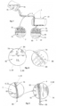
- Embodiments of the invention are explained below referring to the accompanying drawings in which:
- Fig. 1
- shows a perspective schematic view of an aircraft as an example for a vehicle equipped with a hydrogen tank, especially a cryogenic tank for storing liquid hydrogen (LH2);
- Fig. 2
- shows a schematic block diagram of a manufacturing apparatus for manufacturing the hydrogen tank;
- Fig. 3
- shows a schematic perspective view of an example for a wall component manufacturing unit;
- Fig. 4
- shows a schematic view of a graphene applying unit together with a wall component to be coated with graphene;
- Fig. 5
- a perspective view of a graphene spray head used in manufacturing of a graphene layer for the tank of
Fig. 1 ,4 and7 together with an enlarged view of a detail thereof; - Fig. 6
- a schematic view of a graphene flake as shown in the detail of
Fig. 5 ; - Fig. 7
- a partly perspective, partly sectional schematic view of lightweight hydrogen receptacles which are still uncoated during filling with LH2 together with enlarged views of details thereof;
- Fig. 8
- a sectional view of a lightweight hydrogen tank with a still uncoated tank wall partly filled with liquid hydrogen (LH2) together with an enlarged view of a detail thereof near an upper wall;
- Fig. 9
- a sectional view similar to the detail view of
Fig. 8 for a hydrogen tank according to an embodiment of the invention wherein the hydrogen tank wall is coated with graphene, together with an even more enlarged view of a further detail thereof; - Fig. 10
- a view similar to
Fig. 9 wherein a further detail of a part of the tank wall is shown, together with the more enlarged view of the detail thereof; - Fig. 11
- a sectional view through a wall material for a wall component of the hydrogen receptacle made of CFRP which is still uncoated;
- Fig. 12
- a view similar to
Fig. 8 wherein a hydrogen tank is formed from the uncoated wall component ofFig. 11 and wherein a situation is shown that could happen when the hydrogen tank is partly filled with liquid hydrogen; - Fig. 13
- detailed sectional views of a wall area of a hydrogen receptacle that is made from the wall material of
Fig. 11 wherein situations are shown that could occur when liquid hydrogen flows over different surface areas thereof in case that they are still uncoated; - Fig. 14
- a detailed sectional view of a further situation that could happen with the still uncoated wall component during a longer use;
- Fig. 15
- a view as in
Fig. 14 showing a situation that could happen during an even longer use of the uncoated wall component; - Fig. 16
- a schematic view of an example of the wall material as shown as in
Fig. 11 during an application of graphene before a wall of the receptacle wall component is formed therefrom according to another embodiment of the manufacturing thereof; - Fig. 17
- a perspective view of a further embodiment of a wall component manufacturing unit wherein the wall material coated with graphene as shown in
Fig. 16 is used; - Fig. 18
- a view as in
Fig. 13 to 15 wherein the receptacle wall is coated with graphene according to an embodiment of the invention; and - Fig. 19
- a view similar to
Fig. 12 , wherein the receptacle wall is coated with graphene according to an embodiment of the invention. - In the following, preferred embodiments of a
hydrogen receptacle 1 for avehicle 12, especially an aircraft, and manufacturing methods therefore are explained with reference to the accompanying drawings. Thehydrogen receptacle 1 is configured to contain hydrogen, especially liquid hydrogen (referred to as LH2 in the following). Especially, thehydrogen receptacle 1 is configured to store or to conduct LH2. The hydrogen receptacle comprises areceptacle wall 2 made from fibre reinforced composite material defining avolume 3 for storing or conducting hydrogen, especially LH2. Thereceptacle wall 2 comprises aninner layer 4 of graphene. Examples for thehydrogen receptacle 1 arehydrogen tanks 10 andhydrogen pipes 5. The principles of the preferred embodiments will be described mainly with relation to tanks, but they are also applicable to pipes orother hydrogen receptacles 1. -
Fig. 1 shows an aircraft, especially anairplane 44 as an example for avehicle 12 in which ahydrogen tank 10 is used. Theairplane 44 has apropulsion system 46 with turbines 42 as engines 26. The turbines 42 are configured to burn hydrogen supplied from thehydrogen tank 10. Further, theairplane 44 may be equipped with fuel cells (not shown), wherein hydrogen is supplied to the fuel cells from thehydrogen tank 10. - The
hydrogen tank 10 has, e.g., a cylindrical shape. Thehydrogen tank 10 is configured as a cryogenic tank for storing LH2 at cryogenic temperatures. At least onewall component 14 of the tank, such as for example the middlecylindrical part 16 is made of fibre reinforced composite material, especially CFRP (=carbon fibre reinforced plastic). Thehydrogen tank 10 further comprises end caps 18 which may also be made from fibre reinforced composite such as CFRP (so that they are further examples for the fibre reinforced composite wall component 14) or are - as presently preferred - made from metal. Theinner surface 20 of thewall component 14 is coated with acoating 22 of graphene. Here, theinner surface 20 is the surface having contact with the LH2. -
Fig. 2 shows a schematic block diagram of amanufacturing apparatus 50 for manufacturing thehydrogen tank 10 according to a first possible embodiment of a manufacturing method. Themanufacturing apparatus 50 comprises a wallcomponent manufacturing unit 52, agraphene applying unit 54 and atank assembly unit 56. The wallcomponent manufacturing unit 52 is configured for manufacturing thewall component 14 made from fibre reinforced composite material. Thegraphene applying unit 54 is configured to apply alayer 4 or liner of graphene onto at least one surface, especially theinner surface 20, of thewall component 14. The applying of graphene may be made by any suitable graphene production technique as known, for example, from [3] or [4]. Preferably, thegraphene applying unit 54 is configured to apply the graphene by spraying multiple graphene flakes onto the surface. Thetank assembly unit 56 is configured to assemble the at least onewall component 14 coated by graphene together with further components to form thehydrogen tank 10. -
Fig. 3 shows a schematic perspective view of an example for the wallcomponent manufacturing unit 52. The wallcomponent manufacturing unit 52 comprises awinder 58 onto which several layers of CFRP laminates 60 can be wound in order to achieve thewall component 14. -
Fig. 4 shows a schematic view of an embodiment of thegraphene applying unit 54 together with thewall component 14 to be coated with graphene. Thewall component 14 is manufactured and provided as an essentially cylindrical wall element withopenings 62. Thegraphene applying unit 54 comprises arobotic arm 64 adapted and configured to pass through theopening 64 and equipped with agraphene spray head 66 as shown inFig. 5 . Thegraphene applying unit 54 is configured to coat the inner surface of at least onewall component 14 of thehydrogen tank 10 with graphene. - As mentioned above, there are different ways to apply a graphene layer at the receptacle
inner surface 20, such as the inner surface of thehydrogen tank 10. There are different ways to apply a graphene layer at the tank inner surface. One way is by spraying a solution containing graphene "flakes", shown inFig. 5 . -
Fig. 5 shows an example of thegraphene spray head 66. Especially,Fig. 5 shows the application of thegraphene layer 4 on thesurface 20 by sprayinggraphene flakes 68. The detail ofFig. 5 and Fig. 6 show an enlarged view of such agraphene flake 68. Agraphene flake 68 is 150nm to 4µm long and has a thickness of about 1 to 3 carbon atoms. Thegraphene spray head 66 comprises acontainer 70 with solvent containinggraphene flakes 68 and aspray gun 72. TheFig. 5 and 6 display a detail of one graphene "flake" 68, which is 150 nm to 4 mm long and consists of one layer of carbon-atoms. The solvent is kept in thecontainer 70 which is connected to thespray gun 72, by which the solvent is sprayed onto thesurface 20. - It is clear from
Figs. 2 to 5 , that the manufacturing method as described before also works for manufacturing thehydrogen pipe 5. - In the following, several advantages and effects of the
hydrogen receptacle 1 with inner graphene liner will be described referring toFigs. 7 to 15 ,18 and 19 . Therein,Figs. 7, 8 and11 to 15 show different situations whereinhydrogen receptacles 1 withreceptacle walls 2 made of CFRP which are still not provided with a graphene layer are used while theFigs. 9 ,10 ,18 and 19 show the same situations wherein theinner surface 20 of thereceptacle walls 2 made from thesame wall materials 74 is provided with thegraphene layer 4 in accordance with embodiments of the invention. - Referring now to
Fig. 7 ,lightweight hydrogen receptacles 1 thewalls 2 of which are not coated are shown during filling with a liquid 76 from aliquid container 78. Further,Fig. 7 shows enlarged details of an area near a wall of thehydrogen pipe 5 and of an area near the bottom wall of thehydrogen tank 10 shown in an uncoated state in order to explain the effect of static electricity in liquid containers. - It is well established that when a gas or liquid passes over a surface at a sufficient velocity, static electricity may be built up by charged
particles surface 20. A well-known example in aeronautics is static electricity on the wing covers. - The phenomenon appears typically when the
surface 20 is not made of an electrically conducting material, i.e., the charged particles cannot be led away. Static electricity may be built up when a liquid is flushed at a high velocity over asurface 20, such as is the case when filling atank 10. InFig. 7 liquid 76 from acontainer 78 is filled through apipe 5 into atank 10 at a high velocity.Tank 10 andpipe 5 is made of a non-conducting material. Static electricity is built up inpipe 5 and intank 10. -
Fig. 8 shows alightweight hydrogen tank 10 with a stilluncoated tank wall 80 partly filled withLH2 82 together with an enlarged view of a detail thereof near an upper wall portion.Fig. 8 shows aLH2 tank 10. The illustration on the left shows a cross-section of a cylindrical tank with hydrogen in both liquid 82 andgas form 84. The illustration on the right shows a detail withgas permeation 86 through material of thetank wall 80. In this instance thetank wall 80 is built of CFRP, and will therefore display particular permeation, if no separate measures are taken to suppress it. -
Fig. 9 shows the situation as inFig. 8 wherein thetank wall 80 is provided with thegraphene layer 4 in accordance with embodiments of the invention.Fig. 10 shows a lower part of the tank wall provided with thegraphene layer 4 which is electrically connected to ground 88. - An embodiment of the
CFRP LH2 tank 10 as shown inFigs. 9 and10 includes a multi-functionalinner layer 4 of graphene for suppression of static electricity build-up as well as suppression of permeation. Thegraphene layer 4 is electrically grounded (i.e., electrically connected to earth). -
Fig. 9 shows theinner graphene layer 4 in theCFRP LH2 tank 10, wherein a section of thetank 10 is shown in the left illustration, and a detail depicted on the right side ofFig. 10 shows how charged particles of the material surface are led to earth, thus the charged particles in the liquid get dispersed. Especially,Fig. 9 shows aliquid hydrogen tank 10 in accordance with an embodiment of the invention. To the left a partial cross-section through thetank 10 is seen, with liquid hydrogen and gaseous hydrogen. Thetank 10 has theinner surface layer 4 of graphene (a graphene "liner"). To the right a detail is seen of a section withliquid hydrogen 82. It is seen that the chargedsurface particles 90 are led away in thegraphene layer 4, which is connect to ground (earth) 88. Once they are led away the oppositely chargedparticles 92 in the liquid get dispersed, and so no build-up of a charge can take place any longer. -
Fig. 10 illustrates the permeation suppression in theCFRP LH2 tank 10 by thegraphene layer 4. In more detail,Fig. 10 shows the sameliquid hydrogen tank 10 as inFig. 9 , i.e., aCFRP tank 10 with a graphene inner layer (liner) 4 however here focussing on permeation. To the left, a partial section is shown with an overpressure ofhydrogen gas 84. To the right a detail shows that gas that would permeate without thegraphene layer 4, here is hindered from penetrating thegraphene layer 4. - Hence, there are several advantages in applying a
graphene layer 4 to wallcomponents 14 ofhydrogen receptacles 1 some of them are listed in the following: - Enabling of a fast filling through
pipes 5 andtank 10 with liquid hydrogen, with static electricity build-up suppressed by the graphene layer 4 (grounded) - Quicker permeation of hydrogen through CFRP tank cross section is slowed down considerably by the
graphene layer 4 - the
graphene layer 4 is multi-functional by suppressing both static electricity as well as permeation - the
graphene layer 4 is well compatible with CFRP - Enabling of a
CFRP tank 10 with considerable weight saving. - For applying the
graphene layer 4, embodiments of the manufacturing method make use ofgraphene flakes 68 ready in solvent and aspray gun 72. An embodiment of the manufacturing method comprises the steps of - applying the
graphene layer 4 on CFRP inner material (weave or tape), by, e.g., spraying - verify electrical ground function
- verify permeation suppression.
- However, applying a graphene layer to fibre reinforced composite material of or for a
wall component 14 of a hydrogen receptacle provides even more advantages as listed above. Those further effects and advantages are explained in more detail in the following. -
Fig. 11 shows a sectional view through awall material 74 for thewall component 14 of thehydrogen receptacle 1 made of CFRP being still uncoated in order to illustrate potential issues of a porosity of the CFRP material. -
Fig. 11 shows a typical cross-section of a carbon fibre reinforced plastic (CFRP). Especially, aply 94 is shown as an example for thewall material 74. Theply 94 has a polymer matrix andcarbon fibres 96 embedded therein. Theply 94 has resin rich layers 98. On the surface thereof, there areas of a pore free surface and areas withopen pores 102 in the surface. Thetotal thickness 104 of theply 94 varies typically between 0.02 mm (ultra-thin) and 0.25 mm (thick). Typical standard thicknesses are, 0.125 mm (thin), 0.195 mm (medium), and 26 mm (thick). Thicknesses below 0.125 mm are defined as "thin plies". - In the resin various pores are usually present, defined by a porosity content. This is dependent on the curing process, and includes parameters such as pressure and temperature during curing. The pores may vary in size from 4 mm up to appr. 60 mm. The pores are present within the resin, and may appear in the surface as
open pores 102, such as seen inFig. 11. Fig. 11 shows a cross-section of a typical CFRP ply 94 with pores shown internally as well as crossing the surface. -
Fig. 12 shows a cross-section of a cylindrically shapedliquid hydrogen tank 10 built of a laminated CFRP shell on the left side. The situation is shown where thetank wall 80 is manufactured with aCFRP laminate 106 ofseveral plies 94 as shown inFig. 11 without surface treatment. Thetank 10 is partially filled withliquid hydrogen 82 and to a part withgaseous hydrogen 84. An over pressure of Δp bar exists in thetank 10. Permeation ofhydrogen 86 takes place through theCFRP laminate 106. - To the right a detail of the
CFRP laminate 106 is shown, here for simplicity with only threeplies surface 20 with someopen pores 102 is visible. -
Fig. 13 illustrates the fluid dynamics with a porous surface as it would happen when using theCFRP laminate 106 without surface treatment of theinner ply 94 thereof.Fig. 13 illustrates a liquid flow over a smooth surface (left) displayinglaminar flow 108, and over a void (right) displayingturbulent flow 110 near the void. - Given a
liquid hydrogen tank 10 built of CFRP and no particular liner installed on the inside of the CFRP pressure vessel, we obtain the case of a fluid acting on a porous surface. We will here summarize the physics of this case in the particular case of a pressure vessel, to be filled with a liquid medium which will be repeatedly filled and evacuated. -
Fig. 13 shows a liquid flowing nearby a solid surface that is smooth (left). Theliquid velocity 108 is shown by means of a velocity diagram as function of the distance to the surface. Right at thesurface 20 the velocity of the liquid is zero, and it increase by a parabolic function of the distance. The flow in the liquid is here laminar at all distances. - To the right a
surface 20 with a void is shown, here made up by anopen pore 102 in the CFRP resin at thesurface 20. It can here be seen that a turbulent flow is taking place near the surface, and thedistribution 110 of the flow velocity is also changed. - For liquid pressure vessels in operation over years with multiple evacuations and refilling experience has shown that
tiny particles 112 may build up on the inside of the pressure vessel. In particular this has proven to be the case at voids in surfaces.Fig. 14 shows the case of anopen pore 102 with tiny particle build-up 114. Theparticles up 114 can contribute to further turbulent flow. - For maintaining proper function over longer time, it is advantageous to be able to either clean the
inner tank surface 20 from undesired particle build-up 114, (which is often performed by flushing the tank 10); since pressure vessels are often designed so as not to be disassembled, the best option is to utilize such aninner surface 20 that permits as little particle build-up 114 as possible. Clean surfaces are essential to rapid filling and evacuation under laminar flow. - Experience has also proven that
tiny bubbles Fig. 15 . In such cases, bubble build-up 118 can contribute to further turbulent flow.Fig. 15 shows bubbles 118 trapped in open voids inside thetank 10, contributing to turbulent flow. - Also here applies that an
inner tank surface 20 that does not permitbubbles 116 to be trapped and bubble-build-up 118 is a preferred option. - Such advantageous
smooth surfaces 20 can be achieved by thegraphene coating 22. - A 2D layer of one atom thickness of carbon is defined as "graphene". Within the last 20 years, graphene has been intensively researched, and found to possess numerous interesting characteristics.
- The manufacturing of
graphene layers 4 involve chemical exfoliation from graphite, and is described in the literature. Graphene can be provided e.g., in limited "flakes", seeFig. 6 . - For practical applications, graphene can be applied on a
material surface 20 as alayer 4. Such agraphene layer 4 may consist of a multitude ofgraphene flakes 68 that are e.g., sprayed on to the surface, seeFig. 5 orFig. 16 which illustrates the step of applying graphene according to another embodiment of the manufacturing method. -
Fig. 16 shows another embodiment of thegraphene applying unit 54 wherein graphene is applied on thewall material 74 before thewall component 14 is formed from thewall material 74. As described before referring toFigs. 4 and 5 , thegraphene applying unit 54 comprises therobotic arm 64 and thegraphene spray head 66 with thecontainer 70 with solvent as graphene flake source and thespray gun 72 with a spraying nozzle.Fig. 16 further shows theCFRP laminate 106 in form of a tape, amaterial spool 120 containing rolled CFRP tape withgraphene coating 22. - In other instances, different processes can be used for applying graphene onto a substrate, such as e.g., additive manufacturing with dispersed graphene particles, or using graphene bucky paper.
- A CFRP tape coated with graphene has proven to possess several beneficial characteristics, such as smooth surface texture, mechanical, thermal and electrical properties.
- Embodiments of the invention relate to an
inside coating 22 of aCFRP LH2 tank 10, that is sufficiently free of voids so as enable a long term maintenance of theinner tank surface 20, virtually free of: voids causing turbulent flow, particle build-up and bubble build-up, that both can cause added turbulent flow, by applying aninner layer 4 of graphene, e.g. by spraying ofgraphene flakes 68 in a multitude of atom-layers, multi-functionally also suppressing hydrogen permeation, thegraphene layer 4 still being very thin compared to any metal layer, and displaying good material compatibility with the CFRP as a substrate. Advantageously, a clean tankinner surface 20 is achieved, with easy maintenance, enabling rapid filling and evacuation, taking place under laminar flow near the surface. -
Fig. 17 shows aCFRP laminate 106 in form of a tape being laid down on a mandrel 122 (example for forming tool) within the first steps of a manufacturing process of building a CFRPcylindrical LH2 tank 10. For simplicity it is here assumed that the cylindrical region is made by CFRP and the conical end domes of metal. The principles discussed here apply as well to complete CFRP LH2 tanks. - In
Fig. 17 it is seen that theinnermost ply 94 is laid down in a winding process involving atape laying head 124, thematerial spool 120 and arobotic arm 64. The mandrel 122 rotates and provides the shape of thetank 10. The tape used for the innermost ply is a CFRP tape coated with agraphene layer 4, as shown inFig. 16 , in this instance by spraying a multitude ofgraphene flakes 68 onto the tape, providing an even and virtually void free coating. Thetape laying head 124 holds thematerial spool 124 and comprises acompaction roller 126 configured to press the tape onto the mandrel 122. -
Fig. 18 shows a detail of the innermost CFRP ply 94, used as theinner surface 20 in theLH2 tank 10. In the picture avoid 102 is seen. Thesurface 20 is covered by acoating 22 of graphene, e.g., applied by the spraying procedure shown inFig. 16 . For larger voids thecarbon flakes 68 in the first flake layer will fall through, but layer by layer, the void is getting covered. It should be noted that the number of flake layers seen here are simplified, and will in reality be considerably larger. -
Fig. 19 shows a cross-section of the resulting CFRP LH2 tank 10 (left), with acoating 22 of graphene on theinnermost ply graphene coating 22, in this instance applied by sprayinggraphene flakes 68. In the detail it is seen that the smooth surface of thegraphene coating 22 results inlaminar liquid flow 108, and that anyparticles 112 in the liquid are not causing build-up, and there is no bubble build-up. In the cross-section is seen that the hydrogen permeation is reduced by the graphene layer 4 (left).Fig. 19 shows a cross-section of theCFRP LH2 tank 10 withgraphene coating 22 on the inside (left) and detail ofCFRP laminate 106 including the graphene coating 22 (right) displaying fulllaminar flow 108, no particle build-up and no bubble build-up, and the reduced hydrogen permeation is indicated (left). - Hence, some advantages of applying
graphene coating 22 to awall material 74 orwall component 14 of ahydrogenic receptacle 1 are: -
Graphene coating 22 enables laminar flow without voids -
Graphene coating 22 suppresses particle build-up in voids -
Graphene coating 22 suppresses bubble build-up in voids -
Graphene coating 22 enhances maintenance and tank cleaning procedures -
Graphene coating 22 reduces hydrogen permeation through CFRP laminate -
Graphene coating 22 displays high compatibility with CFRP materials -
Graphene coating 22 may suppress static electricity inCFRP LH2 tank 10 - Advantageous technical means for manufacturing the graphene coated hydrogen receptacle wall component are:
- a carbon fibre reinforced plastic composite tape as wall material
- for inner ply: graphene material to apply, e.g.,
graphene flakes 68 - a tape laying heads 124
- a
robotic arm 64 - a mandrel 122
- Embodiments of the methods for manufacturing and operation comprise the following steps:
- apply
graphene layer 4 on CFRP tape, in one instance by spraying graphene material in form offlakes 68 on to the tape, inspect surface for voids - wind inner layer of CFRP LH2 tank with CFRP tape with
graphene layer 4 applied - wind remaining CFRP plies 94, 94T, 94L
-
complete LH2 tank 10, e.g., with possible end domes 18 of metal - test
CFRP LH2 tank 10 under pressure - for longer terms;
test tank 10 for permeation - inspect
tank 10 inside for particle build-up, perform regular maintenance/cleaning oftank 10 - In order to improve operation and functionality of a hydrogen system, especially for aircrafts, the invention provides a hydrogen receptacle (1) for a vehicle (12), especially an aircraft, comprising a receptacle wall (2) made from fibre reinforced composite material defining a volume (3) for storing or conducting hydrogen (82, 84), especially liquid hydrogen (82), wherein the receptacle wall (2) comprises an inner layer (4) of graphene. Further, manufacturing methods for components (14) of the receptacle (1) and for the receptacle (1) itself have been described.
-
- 1
- hydrogen receptacle
- 2
- receptacle wall
- 3
- volume for storing or conducting hydrogen
- 4
- layer of graphene
- 5
- hydrogen pipe
- 10
- hydrogen tank
- 12
- vehicle
- 14
- wall component
- 16
- cylindrical part
- 18
- end cap
- 20
- inner surface
- 22
- graphene coating
- 26
- engine
- 42
- turbine
- 44
- airplane
- 46
- propulsion system
- 50
- manufacturing apparatus
- 52
- wall component manufacturing unit
- 54
- graphene applying unit
- 56
- tank assembly unit
- 58
- winder
- 60
- laminate
- 62
- polar opening
- 64
- robotic arm
- 66
- graphene spray head
- 68
- graphene flake
- 70
- container
- 72
- spray gun
- 74
- wall material
- 76
- liquid
- 78
- liquid container
- 80
- tank wall
- 82
- LH2
- 84
- gaseous hydrogen
- 86
- permeated hydrogen
- 88
- ground
- 90
- charged particles at the surface
- 92
- charged particles in the liquid
- 94
- ply
- 94T
- CFRP ply with transverse fibres
- 94L
- CFRP ply with longitudinal fibres
- 96
- carbon fibre
- 98
- resin rich layer
- 100
- pore free surface
- 102
- open pore in surface (void)
- 104
- total thickness
- 106
- CFRP laminate
- 108
- liquid flow velocity distribution, fully laminar
- 110
- liquid flow velocity distribution, partly turbulent
- 112
- particle flowing in liquid medium
- 114
- particle build-up in open void, contributing to turbulent flow
- 116
- bubble in liquid medium
- 118
- bubble build-up in open void, contributing to turbulent flow
- 120
- material spool
- 122
- forming tool
- 124
- tape laying head
- 126
- compaction roller
Claims (15)
- Hydrogen receptacle (1) for a vehicle (12), especially an aircraft, comprising a receptacle wall (2) made from fibre reinforced composite material defining a volume (3) for storing or conducting hydrogen (82, 84), especially liquid hydrogen (84), wherein the receptacle wall (2) comprises an inner layer (4) of graphene.
- Hydrogen receptacle (1) according to claim 1, characterized in that the inner layer (4) of graphene is at least one of the following:2.1 a coating (22) of an inner surface (20) of the receptacle wall (2);2.2 a coating (22) of the complete inner surface (20) of the receptacle wall (2);2.3 a layer (4) electrically connected to a ground (88) or mass potential;2.4 a cover over voids (102) in the fibre reinforced composite material;2.5 a layer (4) configured to suppress permeation of hydrogen through the receptacle wall (2).
- Hydrogen receptacle (1) according to any of the preceding claims, characterized in that the receptacle wall (2)3.1 is made from CFRP; and/or3.2 comprises a CFRP laminate (106) having a combination of at least two of the layers selected from the group of a resin rich layer made from polymer matrix, a CFRP ply (94, 94T) with fibres in a first direction, and a CFRP ply (94L) with fibres in a second direction; and/or3.3 comprises a CFRP laminate (106) having at least one CFRP ply (94) with unidirectional fibres (96) sandwiched between resin rich layers (98) made from polymer matrix.
- Hydrogen receptacle (1) according to any of the preceding claims, characterized in that the hydrogen receptacle (1) is one of4.1 a hydrogen tank (10) for storing hydrogen wherein the receptacle wall (2) is a tank wall (80) and4.2 a hydrogen pipe (5) for conducting hydrogen wherein the receptacle wall (2) is a pipe wall.
- Manufacturing method for manufacturing a hydrogen receptacle wall component (14), comprising the steps of:a) providing a wall material (74) made from fibre reinforced composite material,b) coating the wall material (74) with graphene layer (4), andc) forming the hydrogen tank wall component (14) from the wall material (74).
- Manufacturing method according to claim 5, characterized in that step a) comprises at least one or several of the steps:a1) providing a carbon fibre reinforced plastic composite ply (94, 94T, 94L),a2) providing a laminate (106) from fibre reinforced composite material, especially CFRP,a3) providing a tape made from fibre reinforced composite material.
- Manufacturing method according to any of the claims 5 or 6, characterized in that step b) is conducted before or after step c).
- Manufacturing method according to any of the claims 5 to 7, characterized in that step b) comprises at least one of the steps:b1) covering voids (102) of the fibre reinforced composite material with the graphene layer (4),b2) coating an inner surface (20) of the wall material (74) which in use forms an inner receptacle wall surface (20) with the graphene layer (4), b3) spraying of multiple graphene flakes (68),b4) covering one side of a tape or laminate (106) from fibre reinforced composite material with graphene,b5) applying graphene to an inner surface (20) of a receptacle wall component (14) formed from fibre reinforced composite material;b6) applying graphene layer (4) on an CFRP tape.
- Manufacturing method according to any of the claims 5 to 8, characterized in that step c) comprises at least one of the steps:c1) applying the wall material (74) to a forming tool,c2) winding the wall material (74) in form of a tape on a mandrel (122),c3) pressing the wall material (74) against a forming tool with a compaction tool, especially a compaction roller (126),c4) forming the wall material (74) to a cylindrical wall,c5) applying several layers of wall material (74) onto a forming tool, especially a mandrel (122) wherein a first layer coated with graphene is applied with the graphene coated side contacting the forming tool;c6) wind an inner layer of CFRP LH2 tank (10) with a tape, especially a CFRP tape, with graphene layer (4) applied and then wind remaining CFRP plies (94T, 94L) on a mandrel (122);c7) curing the wall material (74) after forming.
- Hydrogen receptacle manufacturing method for manufacturing a hydrogen receptacle (1) for a vehicle, especially an aircraft, wherein the hydrogen receptacle (1) comprises a receptacle wall (2) made from fibre reinforced composite material defining a volume (3) for storing or conducting hydrogen, especially liquid hydrogen (82), the hydrogen receptacle manufacturing method comprising the steps of:aa) conducting the manufacturing method according to any of the claims 5 to 9 in order to provide at least one or several wall components (14) andd) assembling several wall components (14) in order to achieve the hydrogen receptacle (1).
- Hydrogen receptacle manufacturing method according to claim 10, characterized in that it is11.1 a hydrogen tank manufacturing method for manufacturing a hydrogen tank (10) for storing hydrogen, especially liquid hydrogen (82) or11.2 a hydrogen pipe manufacturing method for manufacturing a hydrogen pipe (5) for conducting hydrogen, especially liquid hydrogen (82).
- Hydrogen receptacle manufacturing method according to any of the claims 10 or 11, characterized in that12.1 step aa) is conducted such that one or several cylindrical tank components are provided; and/or12.2 step d) comprises assembling at least one cylindrical wall component (14) achieved by step aa) and a first and a second dome shaped end component, especially from metal, in order to achieve a hydrogen tank (10) as receptacle.
- Hydrogen receptacle manufacturing method according to any of the claims 10 to 12, comprising at least one of the following additional steps:g) testing the hydrogen receptacle (1) under pressure,h) testing the hydrogen receptacle (1) for permeation.
- Method according to any of the claims 5 to 13, comprising at least one or several of the following additional steps:e) verifying electrical ground function of the graphene layer (4),f) verifying permeation suppression of the graphene layer (4).
- Aircraft comprising at least one hydrogen consumer and at least one hydrogen receptacle (1) according to any of the claims 1 to 4 or a hydrogen receptacle (1) comprising at least one hydrogen receptacle wall component (14) achieved by the method according to any of the claims 5 to 9 or a hydrogen receptacle (1) achieved by the method according to claim 9 to 14.
Priority Applications (1)
| Application Number | Priority Date | Filing Date | Title |
|---|---|---|---|
| EP22216805.6A EP4393824B1 (en) | 2022-12-27 | 2022-12-27 | Hydrogen receptacle with graphene layer and manufacturing method therefor |
Applications Claiming Priority (1)
| Application Number | Priority Date | Filing Date | Title |
|---|---|---|---|
| EP22216805.6A EP4393824B1 (en) | 2022-12-27 | 2022-12-27 | Hydrogen receptacle with graphene layer and manufacturing method therefor |
Publications (2)
| Publication Number | Publication Date |
|---|---|
| EP4393824A1 true EP4393824A1 (en) | 2024-07-03 |
| EP4393824B1 EP4393824B1 (en) | 2025-06-04 |
Family
ID=84604011
Family Applications (1)
| Application Number | Title | Priority Date | Filing Date |
|---|---|---|---|
| EP22216805.6A Active EP4393824B1 (en) | 2022-12-27 | 2022-12-27 | Hydrogen receptacle with graphene layer and manufacturing method therefor |
Country Status (1)
| Country | Link |
|---|---|
| EP (1) | EP4393824B1 (en) |
Citations (6)
| Publication number | Priority date | Publication date | Assignee | Title |
|---|---|---|---|---|
| EP2902692B1 (en) * | 2013-12-06 | 2017-10-25 | MAGNA STEYR Engineering AG & Co KG | Component of a tank system |
| US20180283613A1 (en) * | 2017-03-31 | 2018-10-04 | United Technologies Corporation | Compressed gas confinement article with barrier coating |
| US20190190041A1 (en) * | 2017-12-15 | 2019-06-20 | Airbus Defence and Space GmbH | Hydrogen storage device |
| CN113072063A (en) * | 2020-07-10 | 2021-07-06 | 华南理工大学 | Hydrogen-resistant coating based on inner surface of hydrogen storage and transportation equipment and preparation method thereof |
| US20220003362A1 (en) * | 2020-07-02 | 2022-01-06 | Airbus Sas | Hydrogen tank and hydrogen pipe that are covered with a two-dimensional material, and plant for delivering hydrogen |
| DE102021103918A1 (en) * | 2021-02-18 | 2022-08-18 | Connova Deutschland GmbH | Hydrogen pressure tank comprising thin load-bearing fiber composite shells with H2 barrier layers and manufacturing method for a hydrogen pressure tank |
-
2022
- 2022-12-27 EP EP22216805.6A patent/EP4393824B1/en active Active
Patent Citations (6)
| Publication number | Priority date | Publication date | Assignee | Title |
|---|---|---|---|---|
| EP2902692B1 (en) * | 2013-12-06 | 2017-10-25 | MAGNA STEYR Engineering AG & Co KG | Component of a tank system |
| US20180283613A1 (en) * | 2017-03-31 | 2018-10-04 | United Technologies Corporation | Compressed gas confinement article with barrier coating |
| US20190190041A1 (en) * | 2017-12-15 | 2019-06-20 | Airbus Defence and Space GmbH | Hydrogen storage device |
| US20220003362A1 (en) * | 2020-07-02 | 2022-01-06 | Airbus Sas | Hydrogen tank and hydrogen pipe that are covered with a two-dimensional material, and plant for delivering hydrogen |
| CN113072063A (en) * | 2020-07-10 | 2021-07-06 | 华南理工大学 | Hydrogen-resistant coating based on inner surface of hydrogen storage and transportation equipment and preparation method thereof |
| DE102021103918A1 (en) * | 2021-02-18 | 2022-08-18 | Connova Deutschland GmbH | Hydrogen pressure tank comprising thin load-bearing fiber composite shells with H2 barrier layers and manufacturing method for a hydrogen pressure tank |
Also Published As
| Publication number | Publication date |
|---|---|
| EP4393824B1 (en) | 2025-06-04 |
Similar Documents
| Publication | Publication Date | Title |
|---|---|---|
| US12331885B2 (en) | Systems and methods for storing, transporting, and using hydrogen | |
| Baroutaji et al. | Comprehensive investigation on hydrogen and fuel cell technology in the aviation and aerospace sectors | |
| Ahluwalia et al. | Liquid hydrogen storage system for heavy duty trucks: Configuration, performance, cost, and safety | |
| Gebrehiwet et al. | Application of composite materials in aerospace & automotive industry | |
| US10309537B2 (en) | Linerless pressure vessel by centrifugal forced weaving and method for manufacturing thereof | |
| EP3498664B1 (en) | Hydrogen-storage device for hydrogen-storage | |
| US20110052845A1 (en) | Method for producing a hollow body | |
| EP3848566B1 (en) | Combustion chamber with solid fuel | |
| EP1384027A1 (en) | Gastight container | |
| Sain et al. | Conceptual design of air and thermal management in a nacelle-integrated fuel cell system for an electric regional aircraft | |
| US11859765B2 (en) | Storage tank for liquid hydrogen | |
| EP4393824B1 (en) | Hydrogen receptacle with graphene layer and manufacturing method therefor | |
| Friedrich et al. | Fuel cell systems for aircraft application | |
| RS67717B1 (en) | A tube transport system for very high vehicle speeds and a method of operating a tube transport system | |
| El-Adawy et al. | Hydrogen-powered aviation: status and perspectives | |
| KIM et al. | Numerical analysis of fillling flow in type III hydrogen tank with different turbulence models | |
| Franke et al. | Elaboration and outlook for metal hydride applications in future hydrogen-powered aviation | |
| US12429166B2 (en) | Cryogenic storage tank, aircraft with a cryogenic storage tank and method for forming a hybrid metal polymer joint | |
| Dannet | Integration of cryogenic tanks and fuel cells for future hydrogen-powered aircraft | |
| EP4286740A1 (en) | Method and apparatus for manufacturing a hydrogen tank wall, and wall component for such tank wall | |
| CN103640699B (en) | A kind of agriculture boat aircraft hopper | |
| AU2012204027B2 (en) | Inert gas distribution system for a fuel tank | |
| EP4438287A1 (en) | Storage tank for liquified gas, aircraft or spacecraft comprising such a storage tank, and fibre metal laminates | |
| CN205452441U (en) | Many boxes methanol -water memory system of fuel cell car | |
| Pendashteh et al. | Discover Nano |
Legal Events
| Date | Code | Title | Description |
|---|---|---|---|
| PUAI | Public reference made under article 153(3) epc to a published international application that has entered the european phase |
Free format text: ORIGINAL CODE: 0009012 |
|
| STAA | Information on the status of an ep patent application or granted ep patent |
Free format text: STATUS: THE APPLICATION HAS BEEN PUBLISHED |
|
| AK | Designated contracting states |
Kind code of ref document: A1 Designated state(s): AL AT BE BG CH CY CZ DE DK EE ES FI FR GB GR HR HU IE IS IT LI LT LU LV MC ME MK MT NL NO PL PT RO RS SE SI SK SM TR |
|
| STAA | Information on the status of an ep patent application or granted ep patent |
Free format text: STATUS: REQUEST FOR EXAMINATION WAS MADE |
|
| 17P | Request for examination filed |
Effective date: 20241220 |
|
| GRAP | Despatch of communication of intention to grant a patent |
Free format text: ORIGINAL CODE: EPIDOSNIGR1 |
|
| STAA | Information on the status of an ep patent application or granted ep patent |
Free format text: STATUS: GRANT OF PATENT IS INTENDED |
|
| INTG | Intention to grant announced |
Effective date: 20250212 |
|
| GRAS | Grant fee paid |
Free format text: ORIGINAL CODE: EPIDOSNIGR3 |
|
| GRAA | (expected) grant |
Free format text: ORIGINAL CODE: 0009210 |
|
| STAA | Information on the status of an ep patent application or granted ep patent |
Free format text: STATUS: THE PATENT HAS BEEN GRANTED |
|
| AK | Designated contracting states |
Kind code of ref document: B1 Designated state(s): AL AT BE BG CH CY CZ DE DK EE ES FI FR GB GR HR HU IE IS IT LI LT LU LV MC ME MK MT NL NO PL PT RO RS SE SI SK SM TR |
|
| REG | Reference to a national code |
Ref country code: GB Ref legal event code: FG4D |
|
| REG | Reference to a national code |
Ref country code: CH Ref legal event code: EP |
|
| REG | Reference to a national code |
Ref country code: DE Ref legal event code: R096 Ref document number: 602022015454 Country of ref document: DE |
|
| REG | Reference to a national code |
Ref country code: IE Ref legal event code: FG4D |
|
| REG | Reference to a national code |
Ref country code: NL Ref legal event code: MP Effective date: 20250604 |
|
| PG25 | Lapsed in a contracting state [announced via postgrant information from national office to epo] |
Ref country code: FI Free format text: LAPSE BECAUSE OF FAILURE TO SUBMIT A TRANSLATION OF THE DESCRIPTION OR TO PAY THE FEE WITHIN THE PRESCRIBED TIME-LIMIT Effective date: 20250604 Ref country code: ES Free format text: LAPSE BECAUSE OF FAILURE TO SUBMIT A TRANSLATION OF THE DESCRIPTION OR TO PAY THE FEE WITHIN THE PRESCRIBED TIME-LIMIT Effective date: 20250604 |
|
| REG | Reference to a national code |
Ref country code: LT Ref legal event code: MG9D |
|
| PG25 | Lapsed in a contracting state [announced via postgrant information from national office to epo] |
Ref country code: NO Free format text: LAPSE BECAUSE OF FAILURE TO SUBMIT A TRANSLATION OF THE DESCRIPTION OR TO PAY THE FEE WITHIN THE PRESCRIBED TIME-LIMIT Effective date: 20250904 Ref country code: GR Free format text: LAPSE BECAUSE OF FAILURE TO SUBMIT A TRANSLATION OF THE DESCRIPTION OR TO PAY THE FEE WITHIN THE PRESCRIBED TIME-LIMIT Effective date: 20250905 |
|
| PG25 | Lapsed in a contracting state [announced via postgrant information from national office to epo] |
Ref country code: PL Free format text: LAPSE BECAUSE OF FAILURE TO SUBMIT A TRANSLATION OF THE DESCRIPTION OR TO PAY THE FEE WITHIN THE PRESCRIBED TIME-LIMIT Effective date: 20250604 |
|
| PG25 | Lapsed in a contracting state [announced via postgrant information from national office to epo] |
Ref country code: BG Free format text: LAPSE BECAUSE OF FAILURE TO SUBMIT A TRANSLATION OF THE DESCRIPTION OR TO PAY THE FEE WITHIN THE PRESCRIBED TIME-LIMIT Effective date: 20250604 |
|
| PG25 | Lapsed in a contracting state [announced via postgrant information from national office to epo] |
Ref country code: HR Free format text: LAPSE BECAUSE OF FAILURE TO SUBMIT A TRANSLATION OF THE DESCRIPTION OR TO PAY THE FEE WITHIN THE PRESCRIBED TIME-LIMIT Effective date: 20250604 |
|
| PG25 | Lapsed in a contracting state [announced via postgrant information from national office to epo] |
Ref country code: RS Free format text: LAPSE BECAUSE OF FAILURE TO SUBMIT A TRANSLATION OF THE DESCRIPTION OR TO PAY THE FEE WITHIN THE PRESCRIBED TIME-LIMIT Effective date: 20250904 |
|
| PG25 | Lapsed in a contracting state [announced via postgrant information from national office to epo] |
Ref country code: LV Free format text: LAPSE BECAUSE OF FAILURE TO SUBMIT A TRANSLATION OF THE DESCRIPTION OR TO PAY THE FEE WITHIN THE PRESCRIBED TIME-LIMIT Effective date: 20250604 |
|
| PG25 | Lapsed in a contracting state [announced via postgrant information from national office to epo] |
Ref country code: NL Free format text: LAPSE BECAUSE OF FAILURE TO SUBMIT A TRANSLATION OF THE DESCRIPTION OR TO PAY THE FEE WITHIN THE PRESCRIBED TIME-LIMIT Effective date: 20250604 |
|
| PG25 | Lapsed in a contracting state [announced via postgrant information from national office to epo] |
Ref country code: PT Free format text: LAPSE BECAUSE OF FAILURE TO SUBMIT A TRANSLATION OF THE DESCRIPTION OR TO PAY THE FEE WITHIN THE PRESCRIBED TIME-LIMIT Effective date: 20251006 |
|
| REG | Reference to a national code |
Ref country code: AT Ref legal event code: MK05 Ref document number: 1800154 Country of ref document: AT Kind code of ref document: T Effective date: 20250604 |
|
| PG25 | Lapsed in a contracting state [announced via postgrant information from national office to epo] |
Ref country code: IS Free format text: LAPSE BECAUSE OF FAILURE TO SUBMIT A TRANSLATION OF THE DESCRIPTION OR TO PAY THE FEE WITHIN THE PRESCRIBED TIME-LIMIT Effective date: 20251004 |
|
| PGFP | Annual fee paid to national office [announced via postgrant information from national office to epo] |
Ref country code: DE Payment date: 20251211 Year of fee payment: 4 |
|
| PG25 | Lapsed in a contracting state [announced via postgrant information from national office to epo] |
Ref country code: SM Free format text: LAPSE BECAUSE OF FAILURE TO SUBMIT A TRANSLATION OF THE DESCRIPTION OR TO PAY THE FEE WITHIN THE PRESCRIBED TIME-LIMIT Effective date: 20250604 Ref country code: AT Free format text: LAPSE BECAUSE OF FAILURE TO SUBMIT A TRANSLATION OF THE DESCRIPTION OR TO PAY THE FEE WITHIN THE PRESCRIBED TIME-LIMIT Effective date: 20250604 |
|
| PGFP | Annual fee paid to national office [announced via postgrant information from national office to epo] |
Ref country code: FR Payment date: 20251229 Year of fee payment: 4 |
|
| PG25 | Lapsed in a contracting state [announced via postgrant information from national office to epo] |
Ref country code: CZ Free format text: LAPSE BECAUSE OF FAILURE TO SUBMIT A TRANSLATION OF THE DESCRIPTION OR TO PAY THE FEE WITHIN THE PRESCRIBED TIME-LIMIT Effective date: 20250604 |
|
| PG25 | Lapsed in a contracting state [announced via postgrant information from national office to epo] |
Ref country code: EE Free format text: LAPSE BECAUSE OF FAILURE TO SUBMIT A TRANSLATION OF THE DESCRIPTION OR TO PAY THE FEE WITHIN THE PRESCRIBED TIME-LIMIT Effective date: 20250604 |
|
| PG25 | Lapsed in a contracting state [announced via postgrant information from national office to epo] |
Ref country code: SK Free format text: LAPSE BECAUSE OF FAILURE TO SUBMIT A TRANSLATION OF THE DESCRIPTION OR TO PAY THE FEE WITHIN THE PRESCRIBED TIME-LIMIT Effective date: 20250604 |
|
| PG25 | Lapsed in a contracting state [announced via postgrant information from national office to epo] |
Ref country code: IT Free format text: LAPSE BECAUSE OF FAILURE TO SUBMIT A TRANSLATION OF THE DESCRIPTION OR TO PAY THE FEE WITHIN THE PRESCRIBED TIME-LIMIT Effective date: 20250604 |
|
| REG | Reference to a national code |
Ref country code: DE Ref legal event code: R097 Ref document number: 602022015454 Country of ref document: DE |
|
| PG25 | Lapsed in a contracting state [announced via postgrant information from national office to epo] |
Ref country code: RO Free format text: LAPSE BECAUSE OF FAILURE TO SUBMIT A TRANSLATION OF THE DESCRIPTION OR TO PAY THE FEE WITHIN THE PRESCRIBED TIME-LIMIT Effective date: 20250604 |
|
| PLBE | No opposition filed within time limit |
Free format text: ORIGINAL CODE: 0009261 |
|
| STAA | Information on the status of an ep patent application or granted ep patent |
Free format text: STATUS: NO OPPOSITION FILED WITHIN TIME LIMIT |
|
| PG25 | Lapsed in a contracting state [announced via postgrant information from national office to epo] |
Ref country code: DK Free format text: LAPSE BECAUSE OF FAILURE TO SUBMIT A TRANSLATION OF THE DESCRIPTION OR TO PAY THE FEE WITHIN THE PRESCRIBED TIME-LIMIT Effective date: 20250604 |
|
| REG | Reference to a national code |
Ref country code: CH Ref legal event code: L10 Free format text: ST27 STATUS EVENT CODE: U-0-0-L10-L00 (AS PROVIDED BY THE NATIONAL OFFICE) Effective date: 20260416 |
|
| 26N | No opposition filed |
Effective date: 20260305 |