EP4393815A1 - Aircraft flap system - Google Patents
Aircraft flap system Download PDFInfo
- Publication number
- EP4393815A1 EP4393815A1 EP22217421.1A EP22217421A EP4393815A1 EP 4393815 A1 EP4393815 A1 EP 4393815A1 EP 22217421 A EP22217421 A EP 22217421A EP 4393815 A1 EP4393815 A1 EP 4393815A1
- Authority
- EP
- European Patent Office
- Prior art keywords
- movable flap
- devices
- torque element
- wing
- aircraft
- Prior art date
- Legal status (The legal status is an assumption and is not a legal conclusion. Google has not performed a legal analysis and makes no representation as to the accuracy of the status listed.)
- Pending
Links
Images
Classifications
-
- B—PERFORMING OPERATIONS; TRANSPORTING
- B64—AIRCRAFT; AVIATION; COSMONAUTICS
- B64C—AEROPLANES; HELICOPTERS
- B64C9/00—Adjustable control surfaces or members, e.g. rudders
- B64C9/14—Adjustable control surfaces or members, e.g. rudders forming slots
- B64C9/16—Adjustable control surfaces or members, e.g. rudders forming slots at the rear of the wing
-
- B—PERFORMING OPERATIONS; TRANSPORTING
- B64—AIRCRAFT; AVIATION; COSMONAUTICS
- B64C—AEROPLANES; HELICOPTERS
- B64C9/00—Adjustable control surfaces or members, e.g. rudders
- B64C9/02—Mounting or supporting thereof
-
- B—PERFORMING OPERATIONS; TRANSPORTING
- B64—AIRCRAFT; AVIATION; COSMONAUTICS
- B64C—AEROPLANES; HELICOPTERS
- B64C3/00—Wings
- B64C3/28—Leading or trailing edges attached to primary structures, e.g. forming fixed slots
-
- B—PERFORMING OPERATIONS; TRANSPORTING
- B64—AIRCRAFT; AVIATION; COSMONAUTICS
- B64C—AEROPLANES; HELICOPTERS
- B64C13/00—Control systems or transmitting systems for actuating flying-control surfaces, lift-increasing flaps, air brakes, or spoilers
- B64C13/24—Transmitting means
- B64C13/26—Transmitting means without power amplification or where power amplification is irrelevant
- B64C13/28—Transmitting means without power amplification or where power amplification is irrelevant mechanical
- B64C13/30—Transmitting means without power amplification or where power amplification is irrelevant mechanical using cable, chain, or rod mechanisms
-
- B—PERFORMING OPERATIONS; TRANSPORTING
- B64—AIRCRAFT; AVIATION; COSMONAUTICS
- B64C—AEROPLANES; HELICOPTERS
- B64C3/00—Wings
- B64C3/38—Adjustment of complete wings or parts thereof
- B64C3/44—Varying camber
- B64C3/50—Varying camber by leading or trailing edge flaps
-
- B—PERFORMING OPERATIONS; TRANSPORTING
- B64—AIRCRAFT; AVIATION; COSMONAUTICS
- B64C—AEROPLANES; HELICOPTERS
- B64C9/00—Adjustable control surfaces or members, e.g. rudders
- B64C9/14—Adjustable control surfaces or members, e.g. rudders forming slots
- B64C9/16—Adjustable control surfaces or members, e.g. rudders forming slots at the rear of the wing
- B64C9/18—Adjustable control surfaces or members, e.g. rudders forming slots at the rear of the wing by single flaps
-
- B—PERFORMING OPERATIONS; TRANSPORTING
- B64—AIRCRAFT; AVIATION; COSMONAUTICS
- B64C—AEROPLANES; HELICOPTERS
- B64C9/00—Adjustable control surfaces or members, e.g. rudders
- B64C9/14—Adjustable control surfaces or members, e.g. rudders forming slots
- B64C9/22—Adjustable control surfaces or members, e.g. rudders forming slots at the front of the wing
-
- B—PERFORMING OPERATIONS; TRANSPORTING
- B64—AIRCRAFT; AVIATION; COSMONAUTICS
- B64D—EQUIPMENT FOR FITTING IN OR TO AIRCRAFT; FLIGHT SUITS; PARACHUTES; ARRANGEMENT OR MOUNTING OF POWER PLANTS OR PROPULSION TRANSMISSIONS IN AIRCRAFT
- B64D37/00—Arrangements in connection with fuel supply for power plant
- B64D37/02—Tanks
- B64D37/04—Arrangement thereof in or on aircraft
Definitions
- An aircraft wing comprising a flap system that is mounted at a leading or trailing edge of the wing.
- the flap system comprises at least two movable flap devices spaced apart in a spanwise direction Y from each other. Each movable flap device is supported by at least one support stations and driven about a hinge axis by at least one drive system.
- the flap system further comprises a synchronising torque element connected to the movable flap devices.
- the synchronising torque element is configured to transmit a torque between the movable flap devices in order to actuate a rotational movement of the movable flap devices.
- the synchronising torque element is positioned between the movable flap devices and around an adjacent system or structural component that is also positioned between the movable flap devices.
- the synchronising torque element is connected to one or more of movable flap devices using universal joint (s).
- a universal joint is advantageous in that it ensure optimal performance of the system being achieved during asymmetrical loading events, e.g. gust or cases of asymmetric wing bending.
- Use at one end of the synchronising torque element is possible if the torque element has sufficient strength to react bending loads at the opposite attachment end to the opposite flap. If so, such an arrangement is less complex and cheaper to manufacture.
- the invention may be applied to aircraft where the system component is an aircraft pylon containing a H2 storage tank or power plant.
- the system component is an aircraft pylon containing a H2 storage tank or power plant.
- Such arrangement is particularly suited in such an arrangement to relieve space allocation requirements.
- Each flap (109, 111) is driven about a hinge axis (117) by at least one drive system (115) comprising a geared rotary actuator (118) and a drive connection strut (120) that is located in the same position as the slave support station (203).
- the flap system (103) further comprises a synchronising torque element (113) connected to the movable flap devices (109, 111).
- the synchronising torque element (113) is connected to at least one movable flap device (109, 111) using a universal joint (201). Use at one end of the synchronising torque element (113) is possible if the torque element (113) has sufficient strength to react bending loads at the opposite attachment end (207) to the opposing flap (109).
- a further universal joint (201) may additionally be implemented at end (207) of the torque element (113) should the spanwise bending loading or sizing of the torque element (113) necessitate it.
Landscapes
- Engineering & Computer Science (AREA)
- Aviation & Aerospace Engineering (AREA)
- Mechanical Engineering (AREA)
- Automation & Control Theory (AREA)
- Transmission Devices (AREA)
- Tires In General (AREA)
Abstract
Description
- The invention relates to a flap system for a wing of an aircraft, an aircraft wing and an aircraft.
- Aircraft and in particular commercial aircraft typically comprise various high lift control surfaces as part of their wings or mounted on the wings. The control surfaces or control devices usually comprise leading edge devices such as slats positioned at the leading edge of a wing and trailing edge devices positioned at the trailing edge of the wing. Trailing edge devices may comprise e.g. flaps, or flaperons and others, each having a specific function and influencing the aerodynamic behaviour and performance of the aircraft. It is important that symmetric deployment of such devices is achieved so that the aircraft remains controllable and stable as the devices are retracted and deployed to the required positions during flight.
- In order to ensure sufficient redundancy in the design so that the devices may be moved in a synchronised way, multiple drive system interfaces per trailing edge device are necessary. So in the example case of an aircraft with two flaps you might see four drive systems interfaces being used to ensure redundancy (2 per flap) for synchronised movement. Normally these drive interfaces are placed within the wing outer surface on each wing either side of a pressurized or unpressurized fuselage or alternatively either side of an engine pylon or high lift assembly on a wing.
- Another approach to satisfying sufficient synchronisation redundancy is to provide one drive interface per flap and an interconnector device such as a torque rod or torque element that connects between the flaps such that in the case of failure of one drive interface, the interconnector device enables both flaps to be driven in a synchronised way to the desired position using a single drive interface at one of the flaps. A limitation to such an arrangement is the positioning of the independent interconnector between flaps through an adjacent component located between the flaps, such as the pylon, or fuselage, or high lift component. This in some cases is not possible as the adjacent component may categorized as a "keep out zone" where such devices are not possible or permitted to pass through. Such a zone may be classified as a "keep out zone" because of space allocation, or due to the fact that the adjacent component being pressurised or containing system components that cannot be repositioned for example an accumulator or engine or a fuel tank.
- It may be seen as an object of the invention to provide a trailing edge system for an aircraft that enables the use of an interconnector device while still meeting the requirement for respecting "keep out zones".
- The abovementioned object may be achieved by the trailing edge system according to claim one. Further advantageous features are subject matter of the dependent claims.
- An aircraft wing is provided comprising a flap system that is mounted at a leading or trailing edge of the wing. The flap system comprises at least two movable flap devices spaced apart in a spanwise direction Y from each other. Each movable flap device is supported by at least one support stations and driven about a hinge axis by at least one drive system. The flap system further comprises a synchronising torque element connected to the movable flap devices. The synchronising torque element is configured to transmit a torque between the movable flap devices in order to actuate a rotational movement of the movable flap devices. The synchronising torque element is positioned between the movable flap devices and around an adjacent system or structural component that is also positioned between the movable flap devices.
- The design as described enables the use of an interconnector device while still meeting the requirement for respecting "keep out zones".
- Preferably the synchronising torque element comprises an axis of rotation that is parallel and eccentric to a hinge line of the movable flap devices. This results in symmetric a design that considers uniform loading across the torque element during operation and accounts for the primary loading being in torque.
- Preferably, the synchronising torque element is connected to one or more of movable flap devices using universal joint (s). The use of a universal joint is advantageous in that it ensure optimal performance of the system being achieved during asymmetrical loading events, e.g. gust or cases of asymmetric wing bending. Use at one end of the synchronising torque element is possible if the torque element has sufficient strength to react bending loads at the opposite attachment end to the opposite flap. If so, such an arrangement is less complex and cheaper to manufacture.
- Preferably the synchronising torque element is supported by a plurality of side stay struts that are each connected to a corresponding flap master support. Such a design is advantageous in that the support principle of the torque element is simplified by avoiding the need for separate support fittings which adds weight and complexity to the overall wing design and would occupy valuable space. Also, use is made of existing master support stations and allows for spanwise loads to be transferred between adjacent devices via the synchronising torque element, thereby reducing weight and complexity.
- Preferably, the invention may be applied to aircraft where the system component is an aircraft pylon containing a H2 storage tank or power plant. Such arrangement is particularly suited in such an arrangement to relieve space allocation requirements.
- Embodiments are presented herein are described below with reference to the following drawings, in which:
-
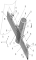
Figure 1 is a combined isometric view and section view of an aircraft (100), a fuselage (107) and a wing (101) attached to the fuselage (107) and comprising a flap system (103) according to an embodiment of the present invention. The section is taken through an aft portion of a propulsion unit (116) that is mounted to the wing (101) between adjacent movable trailing edge flaps (109, 111) -
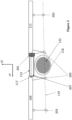
Figure 2 is a combined rear and section view of the aircraft wing (101), flap system (103) and propulsion unit (116) arrangement offigure 1 . The section is taken through an aft portion of a propulsion unit (116) through a parallel plane to plane ZY. -
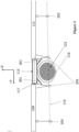
Figure 3 is a combined rear and section view of an embodiment of the aircraft wing (101), flap system (103) and propulsion unit (116) arrangement offigure 1 and2 . The section is taken through an aft portion of a propulsion unit (116) through a parallel plane to plane ZY. - With reference to all figures, in a typical coordinate convention appreciated by the skilled person, the X, Y and Z axes correspond to a set of orthogonal aircraft axes, whereby X is the longitudinal aircraft axis, Y corresponds to the lateral aircraft axis oriented in a spanwise direction of the wing of the aircraft, and the direction Z corresponds to the vertical axis, these three directions being orthogonal to each other, and create a set of three orthogonal planes with respect to each other. It should also be noted that typically the freestream direction S is approximately co-linear with the airplane X axis when the aircraft is in steady and level flight.
-
Figures 1 and2 shows an aircraft wing (101) mounted to a fuselage portion (107) of an aircraft (100). The wing (101) extends between a root portion (121) and a tip portion (123) in a spanwise direction Y, and is provided with a flap system (103) that is mounted at a trailing edge region (104) of the wing. As previously mentioned, such a system (103) may be implemented at the leading edge (106) of the wing (101) if desired. The flap system (103) comprises at least two movable flap devices (109, 111) spaced apart in a spanwise direction Y from each other. Each movable flap device (109, 111) is supported by a plurality of support stations categorised as master support stations (205) and slave support stations (203). Master support stations (205) support the flap device (109, 111) in all but one degrees of freedom (a rotational DOF), whereas the slave support stations (203) permit the flaps (109, 111) to displace in an additional DOF in the spanwise Y direction. Each flap (109, 111) is driven about a hinge axis (117) by at least one drive system (115) comprising a geared rotary actuator (118) and a drive connection strut (120) that is located in the same position as the slave support station (203). The flap system (103) further comprises a synchronising torque element (113) connected to the movable flap devices (109, 111). The synchronising torque element (113) is configured to transmit a torque between the movable flap devices (109, 111) in order to actuate a rotational movement of the movable flap devices (109, 111) in a synchronous way about the flap hinge axis (119) when only one drive system (115) is capable of effecting movement of the flap system (103). The synchronising torque element is positioned between the movable flap devices (109, 111) and around an adjacent H2 propulsion unit (116) which is a combined system of structural and system components and which also positioned between the movable flap devices (109, 111). The propulsion unit (116) comprises a "keep out zone" (122), through which components not associated with the operation of the propulsion unit (116) may not pass. The synchronising torque element (113) comprises an axis of rotation (117) that is parallel and offset or eccentric to a hinge line (119) of the movable flap devices (109, 111) ,as shown. - As can be seen in
figure 2 , the synchronising torque element (113) is connected to at least one movable flap device (109, 111) using a universal joint (201). Use at one end of the synchronising torque element (113) is possible if the torque element (113) has sufficient strength to react bending loads at the opposite attachment end (207) to the opposing flap (109). A further universal joint (201) may additionally be implemented at end (207) of the torque element (113) should the spanwise bending loading or sizing of the torque element (113) necessitate it. - With reference to
figure 3 , an aircraft wing (101) substantially in accordance with the embodiment offigures 1 and2 is shown, wherein the synchronising torque element (113) is supported by a plurality of side stay struts (301) that are each connected to a corresponding flap master supports (205). Each side stay struts (301) comprise a pivot type attachment at each ends to the torque element (113) and the master support station (205) so as to permit the torque element (113) to orbit the hinge axis (119) at a pre-specified distance, determined by the size of the overall flap system (103) and wing (101) - Where in the foregoing description, integers or elements are mentioned which have known, obvious or foreseeable equivalents; then such equivalents are herein incorporated as if individually set forth. Reference should be made to the claims for determining the true scope of the present invention, which should be construed so as to encompass any such equivalents. It will also be appreciated by the reader that integers or features of the invention that are described as preferable, advantageous, convenient or the like are optional and do not limit the scope of the independent claims. Moreover, it is to be understood that such optional integers or features, whilst of possible benefit in some embodiments of the invention, may not be desirable, and may therefore be absent, in other embodiments.
- While at least one exemplary embodiment is disclosed herein, it should be understood that modifications, substitutions and alternatives may be apparent to one of ordinary skill in the art and can be made without departing from the scope of this disclosure. This disclosure is intended to cover any adaptations or variations of the exemplary embodiment(s). In addition, in this disclosure, the terms "comprise" or "comprising" do not exclude other elements or steps, the terms "a" or "one" do not exclude a plural number, and the term "or" means either or both. Furthermore, characteristics or steps which have been described may also be used in combination with other characteristics or steps and in any order unless the disclosure or context suggests otherwise. This disclosure hereby incorporates by reference the complete disclosure of any patent or application from which it claims benefit or priority.
Claims (6)
- An aircraft wing (101) comprising a flap system (103) that is mounted at a leading or trailing edge (105, 107) of the wing (101) and comprises at least two movable flap devices (109, 111) spaced apart in a spanwise direction Y from each other, wherein each movable flap device (109, 111) is supported by at least one support station (203, 205) and is driven about a hinge axis (119) by at least one drive system (115), wherein the flap system (103) further comprises a synchronising torque element (113) connected to the movable flap devices (109, 111), wherein the synchronising torque element (113) is configured to transmit a torque between the movable flap devices (109, 111) in order to actuate a rotational movement of the movable flap devices (109, 111), and wherein the synchronising torque element (113) is positioned between the movable flap devices (109, 111) and around an adjacent system or structural component (116) that is also positioned between the movable flap devices (109, 111).
- An aircraft wing (101) according to claim 1, wherein the synchronising torque element (113) comprises an axis of rotation (117) that is parallel and eccentric to a hinge line (119) of the movable flap devices (109, 111).
- An aircraft wing (101) according to any preceding claim, wherein the synchronising torque element (113) is connected to at least one movable flap device (109, 111) using a universal joint (201).
- An aircraft wing (101) according to any preceding claim, wherein the synchronising torque element (113) is supported by a plurality of side stay struts (301) that are each connected to a corresponding flap master support(205).
- An aircraft wing (101) according to any preceding claim, wherein the system component (116) is an aircraft pylon containing a H2 storage tank.
- An aircraft (100) comprising a wing (101) according to any preceding claim.
Priority Applications (3)
| Application Number | Priority Date | Filing Date | Title |
|---|---|---|---|
| EP22217421.1A EP4393815A1 (en) | 2022-12-30 | 2022-12-30 | Aircraft flap system |
| US18/396,967 US12330785B2 (en) | 2022-12-30 | 2023-12-27 | Aircraft flap system |
| CN202311837558.0A CN118270224A (en) | 2022-12-30 | 2023-12-28 | Aircraft wing and aircraft |
Applications Claiming Priority (1)
| Application Number | Priority Date | Filing Date | Title |
|---|---|---|---|
| EP22217421.1A EP4393815A1 (en) | 2022-12-30 | 2022-12-30 | Aircraft flap system |
Publications (1)
| Publication Number | Publication Date |
|---|---|
| EP4393815A1 true EP4393815A1 (en) | 2024-07-03 |
Family
ID=84767067
Family Applications (1)
| Application Number | Title | Priority Date | Filing Date |
|---|---|---|---|
| EP22217421.1A Pending EP4393815A1 (en) | 2022-12-30 | 2022-12-30 | Aircraft flap system |
Country Status (3)
| Country | Link |
|---|---|
| US (1) | US12330785B2 (en) |
| EP (1) | EP4393815A1 (en) |
| CN (1) | CN118270224A (en) |
Citations (3)
| Publication number | Priority date | Publication date | Assignee | Title |
|---|---|---|---|---|
| US4441675A (en) * | 1982-06-25 | 1984-04-10 | Mcdonnell Douglas Corporation | High lift surface actuation system |
| US4789119A (en) * | 1986-11-07 | 1988-12-06 | Aerospatiale Societe Nationale Industrielle | System for controlling the high-lift flaps of an aircraft |
| US6224022B1 (en) * | 1999-02-26 | 2001-05-01 | Smiths Industries Actuation Systems Inc. | Airplane high lift surface drive system |
Family Cites Families (3)
| Publication number | Priority date | Publication date | Assignee | Title |
|---|---|---|---|---|
| US10696380B2 (en) * | 2017-07-20 | 2020-06-30 | Hamilton Sunstrand Corporation | Aerodynamic control surface operating system for aircraft using variable transmission |
| US12291348B2 (en) * | 2021-01-22 | 2025-05-06 | Blue Spirit Aero Sas | Aircraft propulsion module and aircraft |
| FR3123050A1 (en) * | 2021-05-20 | 2022-11-25 | Airbus Sas | TANK SYSTEM COMPRISING A FRAME, A DIHYDROGEN TANK AND MEANS FOR ATTACHING THE TANK TO THE FRAME |
-
2022
- 2022-12-30 EP EP22217421.1A patent/EP4393815A1/en active Pending
-
2023
- 2023-12-27 US US18/396,967 patent/US12330785B2/en active Active
- 2023-12-28 CN CN202311837558.0A patent/CN118270224A/en active Pending
Patent Citations (3)
| Publication number | Priority date | Publication date | Assignee | Title |
|---|---|---|---|---|
| US4441675A (en) * | 1982-06-25 | 1984-04-10 | Mcdonnell Douglas Corporation | High lift surface actuation system |
| US4789119A (en) * | 1986-11-07 | 1988-12-06 | Aerospatiale Societe Nationale Industrielle | System for controlling the high-lift flaps of an aircraft |
| US6224022B1 (en) * | 1999-02-26 | 2001-05-01 | Smiths Industries Actuation Systems Inc. | Airplane high lift surface drive system |
Also Published As
| Publication number | Publication date |
|---|---|
| US12330785B2 (en) | 2025-06-17 |
| CN118270224A (en) | 2024-07-02 |
| US20240217648A1 (en) | 2024-07-04 |
Similar Documents
| Publication | Publication Date | Title |
|---|---|---|
| RU2724940C2 (en) | Vertical take-off and landing aircraft with hybrid power plant | |
| EP3118104B1 (en) | Pinned fuselage-to-wing connection | |
| EP2032434B1 (en) | Link mechanisms for gapped rigid krueger flaps, and associated systems and methods | |
| EP2234877B1 (en) | Aircraft control surface | |
| EP3263446B1 (en) | Folding wing | |
| US5921506A (en) | Extendible leading edge flap | |
| EP2099676B1 (en) | Bearingless rotor blade assembly for a high speed rotary-wing aircraft | |
| US11591067B2 (en) | Rotating double trapped roller auxiliary track mechanism | |
| Gilbert | Mission adaptive wing system for tactical aircraft | |
| CA2675127C (en) | A leading edge structure for an aerofoil | |
| EP2084055A1 (en) | Rotor system with pitch flap coupling | |
| EP3388331B1 (en) | Slidable divergent trailing edge device | |
| WO2015150817A1 (en) | An aircraft wing with a wing tip device and a strut | |
| EP4026769A1 (en) | Landing gear door system for a landing gear compartment | |
| EP4282750A1 (en) | Moveable wing tip arrangements | |
| EP4282752A2 (en) | Aircraft landing gear assembly | |
| US12330785B2 (en) | Aircraft flap system | |
| EP4227212B1 (en) | Airplane wings | |
| EP3564130B1 (en) | Hybrid ram air turbine with in-line hydraulic pump and generator | |
| US3944170A (en) | Apparatus for producing pivotal movement | |
| US20240017817A1 (en) | Wing for an aircraft | |
| CN116176829A (en) | Aerodynamic control surface assembly | |
| US12319402B2 (en) | Drive mechanism | |
| CN115583333B (en) | Airfoil of aerodynamic surface and aerodynamic surface | |
| EP2530011A2 (en) | Deployable aerodynamic devices with reduced actuator loads |
Legal Events
| Date | Code | Title | Description |
|---|---|---|---|
| PUAI | Public reference made under article 153(3) epc to a published international application that has entered the european phase |
Free format text: ORIGINAL CODE: 0009012 |
|
| STAA | Information on the status of an ep patent application or granted ep patent |
Free format text: STATUS: THE APPLICATION HAS BEEN PUBLISHED |
|
| AK | Designated contracting states |
Kind code of ref document: A1 Designated state(s): AL AT BE BG CH CY CZ DE DK EE ES FI FR GB GR HR HU IE IS IT LI LT LU LV MC ME MK MT NL NO PL PT RO RS SE SI SK SM TR |
|
| STAA | Information on the status of an ep patent application or granted ep patent |
Free format text: STATUS: REQUEST FOR EXAMINATION WAS MADE |
|
| 17P | Request for examination filed |
Effective date: 20250103 |
|
| STAA | Information on the status of an ep patent application or granted ep patent |
Free format text: STATUS: EXAMINATION IS IN PROGRESS |
|
| 17Q | First examination report despatched |
Effective date: 20250829 |
|
| GRAP | Despatch of communication of intention to grant a patent |
Free format text: ORIGINAL CODE: EPIDOSNIGR1 |
|
| STAA | Information on the status of an ep patent application or granted ep patent |
Free format text: STATUS: GRANT OF PATENT IS INTENDED |