EP4393806A2 - Drive unit for human-powered vehicle - Google Patents
Drive unit for human-powered vehicle Download PDFInfo
- Publication number
- EP4393806A2 EP4393806A2 EP23216389.9A EP23216389A EP4393806A2 EP 4393806 A2 EP4393806 A2 EP 4393806A2 EP 23216389 A EP23216389 A EP 23216389A EP 4393806 A2 EP4393806 A2 EP 4393806A2
- Authority
- EP
- European Patent Office
- Prior art keywords
- speed
- ratio
- transmission
- transmission device
- driving force
- Prior art date
- Legal status (The legal status is an assumption and is not a legal conclusion. Google has not performed a legal analysis and makes no representation as to the accuracy of the status listed.)
- Pending
Links
- 230000005540 biological transmission Effects 0.000 claims abstract description 534
- 239000003638 chemical reducing agent Substances 0.000 claims abstract description 252
- 230000009467 reduction Effects 0.000 claims description 48
- 239000011347 resin Substances 0.000 claims description 19
- 229920005989 resin Polymers 0.000 claims description 19
- 239000000463 material Substances 0.000 claims description 10
- 239000007769 metal material Substances 0.000 claims description 8
- 230000007246 mechanism Effects 0.000 description 32
- 238000010586 diagram Methods 0.000 description 11
- 230000008878 coupling Effects 0.000 description 4
- 238000010168 coupling process Methods 0.000 description 4
- 238000005859 coupling reaction Methods 0.000 description 4
- 230000007423 decrease Effects 0.000 description 4
- -1 polyethylene Polymers 0.000 description 4
- 229920001169 thermoplastic Polymers 0.000 description 4
- 229920001187 thermosetting polymer Polymers 0.000 description 4
- 239000004416 thermosoftening plastic Substances 0.000 description 4
- 230000003247 decreasing effect Effects 0.000 description 3
- XEEYBQQBJWHFJM-UHFFFAOYSA-N Iron Chemical compound [Fe] XEEYBQQBJWHFJM-UHFFFAOYSA-N 0.000 description 2
- 239000004734 Polyphenylene sulfide Substances 0.000 description 2
- 229910000831 Steel Inorganic materials 0.000 description 2
- XBDQKXXYIPTUBI-UHFFFAOYSA-N dimethylselenoniopropionate Natural products CCC(O)=O XBDQKXXYIPTUBI-UHFFFAOYSA-N 0.000 description 2
- 229920000069 polyphenylene sulfide Polymers 0.000 description 2
- 239000010959 steel Substances 0.000 description 2
- DHKHKXVYLBGOIT-UHFFFAOYSA-N 1,1-Diethoxyethane Chemical compound CCOC(C)OCC DHKHKXVYLBGOIT-UHFFFAOYSA-N 0.000 description 1
- 125000003903 2-propenyl group Chemical group [H]C([*])([H])C([H])=C([H])[H] 0.000 description 1
- 229920000178 Acrylic resin Polymers 0.000 description 1
- 239000004925 Acrylic resin Substances 0.000 description 1
- 229910000838 Al alloy Inorganic materials 0.000 description 1
- 239000001856 Ethyl cellulose Substances 0.000 description 1
- ZZSNKZQZMQGXPY-UHFFFAOYSA-N Ethyl cellulose Chemical compound CCOCC1OC(OC)C(OCC)C(OCC)C1OC1C(O)C(O)C(OC)C(CO)O1 ZZSNKZQZMQGXPY-UHFFFAOYSA-N 0.000 description 1
- JHWNWJKBPDFINM-UHFFFAOYSA-N Laurolactam Chemical compound O=C1CCCCCCCCCCCN1 JHWNWJKBPDFINM-UHFFFAOYSA-N 0.000 description 1
- 239000004640 Melamine resin Substances 0.000 description 1
- 229920000877 Melamine resin Polymers 0.000 description 1
- 229910000861 Mg alloy Inorganic materials 0.000 description 1
- 239000000020 Nitrocellulose Substances 0.000 description 1
- 229920000299 Nylon 12 Polymers 0.000 description 1
- 229920002292 Nylon 6 Polymers 0.000 description 1
- 229920002302 Nylon 6,6 Polymers 0.000 description 1
- 239000007977 PBT buffer Substances 0.000 description 1
- 239000002033 PVDF binder Substances 0.000 description 1
- 239000004962 Polyamide-imide Substances 0.000 description 1
- 239000004697 Polyetherimide Substances 0.000 description 1
- 239000004698 Polyethylene Substances 0.000 description 1
- 239000004743 Polypropylene Substances 0.000 description 1
- 239000004793 Polystyrene Substances 0.000 description 1
- 229920001328 Polyvinylidene chloride Polymers 0.000 description 1
- XUIMIQQOPSSXEZ-UHFFFAOYSA-N Silicon Chemical compound [Si] XUIMIQQOPSSXEZ-UHFFFAOYSA-N 0.000 description 1
- 229910001069 Ti alloy Inorganic materials 0.000 description 1
- 229920001807 Urea-formaldehyde Polymers 0.000 description 1
- SMEGJBVQLJJKKX-HOTMZDKISA-N [(2R,3S,4S,5R,6R)-5-acetyloxy-3,4,6-trihydroxyoxan-2-yl]methyl acetate Chemical compound CC(=O)OC[C@@H]1[C@H]([C@@H]([C@H]([C@@H](O1)O)OC(=O)C)O)O SMEGJBVQLJJKKX-HOTMZDKISA-N 0.000 description 1
- FJWGYAHXMCUOOM-QHOUIDNNSA-N [(2s,3r,4s,5r,6r)-2-[(2r,3r,4s,5r,6s)-4,5-dinitrooxy-2-(nitrooxymethyl)-6-[(2r,3r,4s,5r,6s)-4,5,6-trinitrooxy-2-(nitrooxymethyl)oxan-3-yl]oxyoxan-3-yl]oxy-3,5-dinitrooxy-6-(nitrooxymethyl)oxan-4-yl] nitrate Chemical compound O([C@@H]1O[C@@H]([C@H]([C@H](O[N+]([O-])=O)[C@H]1O[N+]([O-])=O)O[C@H]1[C@@H]([C@@H](O[N+]([O-])=O)[C@H](O[N+]([O-])=O)[C@@H](CO[N+]([O-])=O)O1)O[N+]([O-])=O)CO[N+](=O)[O-])[C@@H]1[C@@H](CO[N+]([O-])=O)O[C@@H](O[N+]([O-])=O)[C@H](O[N+]([O-])=O)[C@H]1O[N+]([O-])=O FJWGYAHXMCUOOM-QHOUIDNNSA-N 0.000 description 1
- 239000011354 acetal resin Substances 0.000 description 1
- 229940081735 acetylcellulose Drugs 0.000 description 1
- 229920000122 acrylonitrile butadiene styrene Polymers 0.000 description 1
- 229920002678 cellulose Polymers 0.000 description 1
- 239000001913 cellulose Substances 0.000 description 1
- 229920002301 cellulose acetate Polymers 0.000 description 1
- 230000008859 change Effects 0.000 description 1
- 238000001514 detection method Methods 0.000 description 1
- 230000000694 effects Effects 0.000 description 1
- 239000003822 epoxy resin Substances 0.000 description 1
- 229920001249 ethyl cellulose Polymers 0.000 description 1
- 235000019325 ethyl cellulose Nutrition 0.000 description 1
- 239000007849 furan resin Substances 0.000 description 1
- 229910052742 iron Inorganic materials 0.000 description 1
- 238000000034 method Methods 0.000 description 1
- 229920001220 nitrocellulos Polymers 0.000 description 1
- 229940079938 nitrocellulose Drugs 0.000 description 1
- 239000005011 phenolic resin Substances 0.000 description 1
- 229920002493 poly(chlorotrifluoroethylene) Polymers 0.000 description 1
- 229920002312 polyamide-imide Polymers 0.000 description 1
- 229920001707 polybutylene terephthalate Polymers 0.000 description 1
- 239000004417 polycarbonate Substances 0.000 description 1
- 229920000515 polycarbonate Polymers 0.000 description 1
- 239000005023 polychlorotrifluoroethylene (PCTFE) polymer Substances 0.000 description 1
- 229920000647 polyepoxide Polymers 0.000 description 1
- 229920001601 polyetherimide Polymers 0.000 description 1
- 229920000573 polyethylene Polymers 0.000 description 1
- 229920000139 polyethylene terephthalate Polymers 0.000 description 1
- 239000005020 polyethylene terephthalate Substances 0.000 description 1
- 229920001721 polyimide Polymers 0.000 description 1
- 239000009719 polyimide resin Substances 0.000 description 1
- 229920006324 polyoxymethylene Polymers 0.000 description 1
- 229920001155 polypropylene Polymers 0.000 description 1
- 229920002223 polystyrene Polymers 0.000 description 1
- 239000004810 polytetrafluoroethylene Substances 0.000 description 1
- 229920001343 polytetrafluoroethylene Polymers 0.000 description 1
- 239000004814 polyurethane Substances 0.000 description 1
- 229920002635 polyurethane Polymers 0.000 description 1
- 239000004800 polyvinyl chloride Substances 0.000 description 1
- 229920000915 polyvinyl chloride Polymers 0.000 description 1
- 239000005033 polyvinylidene chloride Substances 0.000 description 1
- 229920002981 polyvinylidene fluoride Polymers 0.000 description 1
- 235000019260 propionic acid Nutrition 0.000 description 1
- 229940095574 propionic acid Drugs 0.000 description 1
- IUVKMZGDUIUOCP-BTNSXGMBSA-N quinbolone Chemical compound O([C@H]1CC[C@H]2[C@H]3[C@@H]([C@]4(C=CC(=O)C=C4CC3)C)CC[C@@]21C)C1=CCCC1 IUVKMZGDUIUOCP-BTNSXGMBSA-N 0.000 description 1
- 229910052710 silicon Inorganic materials 0.000 description 1
- 239000010703 silicon Substances 0.000 description 1
- 229910001256 stainless steel alloy Inorganic materials 0.000 description 1
- 229920006305 unsaturated polyester Polymers 0.000 description 1
- 238000011144 upstream manufacturing Methods 0.000 description 1
Images







Classifications
-
- B—PERFORMING OPERATIONS; TRANSPORTING
- B62—LAND VEHICLES FOR TRAVELLING OTHERWISE THAN ON RAILS
- B62M—RIDER PROPULSION OF WHEELED VEHICLES OR SLEDGES; POWERED PROPULSION OF SLEDGES OR SINGLE-TRACK CYCLES; TRANSMISSIONS SPECIALLY ADAPTED FOR SUCH VEHICLES
- B62M6/00—Rider propulsion of wheeled vehicles with additional source of power, e.g. combustion engine or electric motor
- B62M6/40—Rider propelled cycles with auxiliary electric motor
- B62M6/55—Rider propelled cycles with auxiliary electric motor power-driven at crank shafts parts
-
- B—PERFORMING OPERATIONS; TRANSPORTING
- B62—LAND VEHICLES FOR TRAVELLING OTHERWISE THAN ON RAILS
- B62M—RIDER PROPULSION OF WHEELED VEHICLES OR SLEDGES; POWERED PROPULSION OF SLEDGES OR SINGLE-TRACK CYCLES; TRANSMISSIONS SPECIALLY ADAPTED FOR SUCH VEHICLES
- B62M9/00—Transmissions characterised by use of an endless chain, belt, or the like
- B62M9/04—Transmissions characterised by use of an endless chain, belt, or the like of changeable ratio
-
- B—PERFORMING OPERATIONS; TRANSPORTING
- B62—LAND VEHICLES FOR TRAVELLING OTHERWISE THAN ON RAILS
- B62M—RIDER PROPULSION OF WHEELED VEHICLES OR SLEDGES; POWERED PROPULSION OF SLEDGES OR SINGLE-TRACK CYCLES; TRANSMISSIONS SPECIALLY ADAPTED FOR SUCH VEHICLES
- B62M11/00—Transmissions characterised by the use of interengaging toothed wheels or frictionally-engaging wheels
- B62M11/04—Transmissions characterised by the use of interengaging toothed wheels or frictionally-engaging wheels of changeable ratio
-
- B—PERFORMING OPERATIONS; TRANSPORTING
- B62—LAND VEHICLES FOR TRAVELLING OTHERWISE THAN ON RAILS
- B62M—RIDER PROPULSION OF WHEELED VEHICLES OR SLEDGES; POWERED PROPULSION OF SLEDGES OR SINGLE-TRACK CYCLES; TRANSMISSIONS SPECIALLY ADAPTED FOR SUCH VEHICLES
- B62M11/00—Transmissions characterised by the use of interengaging toothed wheels or frictionally-engaging wheels
- B62M11/04—Transmissions characterised by the use of interengaging toothed wheels or frictionally-engaging wheels of changeable ratio
- B62M11/14—Transmissions characterised by the use of interengaging toothed wheels or frictionally-engaging wheels of changeable ratio with planetary gears
- B62M11/18—Transmissions characterised by the use of interengaging toothed wheels or frictionally-engaging wheels of changeable ratio with planetary gears with a plurality of planetary gear units
-
- B—PERFORMING OPERATIONS; TRANSPORTING
- B62—LAND VEHICLES FOR TRAVELLING OTHERWISE THAN ON RAILS
- B62M—RIDER PROPULSION OF WHEELED VEHICLES OR SLEDGES; POWERED PROPULSION OF SLEDGES OR SINGLE-TRACK CYCLES; TRANSMISSIONS SPECIALLY ADAPTED FOR SUCH VEHICLES
- B62M6/00—Rider propulsion of wheeled vehicles with additional source of power, e.g. combustion engine or electric motor
- B62M6/40—Rider propelled cycles with auxiliary electric motor
-
- B—PERFORMING OPERATIONS; TRANSPORTING
- B62—LAND VEHICLES FOR TRAVELLING OTHERWISE THAN ON RAILS
- B62M—RIDER PROPULSION OF WHEELED VEHICLES OR SLEDGES; POWERED PROPULSION OF SLEDGES OR SINGLE-TRACK CYCLES; TRANSMISSIONS SPECIALLY ADAPTED FOR SUCH VEHICLES
- B62M6/00—Rider propulsion of wheeled vehicles with additional source of power, e.g. combustion engine or electric motor
- B62M6/40—Rider propelled cycles with auxiliary electric motor
- B62M6/60—Rider propelled cycles with auxiliary electric motor power-driven at axle parts
- B62M6/65—Rider propelled cycles with auxiliary electric motor power-driven at axle parts with axle and driving shaft arranged coaxially
-
- B—PERFORMING OPERATIONS; TRANSPORTING
- B62—LAND VEHICLES FOR TRAVELLING OTHERWISE THAN ON RAILS
- B62M—RIDER PROPULSION OF WHEELED VEHICLES OR SLEDGES; POWERED PROPULSION OF SLEDGES OR SINGLE-TRACK CYCLES; TRANSMISSIONS SPECIALLY ADAPTED FOR SUCH VEHICLES
- B62M11/00—Transmissions characterised by the use of interengaging toothed wheels or frictionally-engaging wheels
- B62M11/04—Transmissions characterised by the use of interengaging toothed wheels or frictionally-engaging wheels of changeable ratio
- B62M11/14—Transmissions characterised by the use of interengaging toothed wheels or frictionally-engaging wheels of changeable ratio with planetary gears
- B62M11/145—Transmissions characterised by the use of interengaging toothed wheels or frictionally-engaging wheels of changeable ratio with planetary gears built in, or adjacent to, the bottom bracket
-
- B—PERFORMING OPERATIONS; TRANSPORTING
- B62—LAND VEHICLES FOR TRAVELLING OTHERWISE THAN ON RAILS
- B62M—RIDER PROPULSION OF WHEELED VEHICLES OR SLEDGES; POWERED PROPULSION OF SLEDGES OR SINGLE-TRACK CYCLES; TRANSMISSIONS SPECIALLY ADAPTED FOR SUCH VEHICLES
- B62M11/00—Transmissions characterised by the use of interengaging toothed wheels or frictionally-engaging wheels
- B62M11/04—Transmissions characterised by the use of interengaging toothed wheels or frictionally-engaging wheels of changeable ratio
- B62M11/14—Transmissions characterised by the use of interengaging toothed wheels or frictionally-engaging wheels of changeable ratio with planetary gears
- B62M11/16—Transmissions characterised by the use of interengaging toothed wheels or frictionally-engaging wheels of changeable ratio with planetary gears built in, or adjacent to, the ground-wheel hub
-
- B—PERFORMING OPERATIONS; TRANSPORTING
- B62—LAND VEHICLES FOR TRAVELLING OTHERWISE THAN ON RAILS
- B62M—RIDER PROPULSION OF WHEELED VEHICLES OR SLEDGES; POWERED PROPULSION OF SLEDGES OR SINGLE-TRACK CYCLES; TRANSMISSIONS SPECIALLY ADAPTED FOR SUCH VEHICLES
- B62M9/00—Transmissions characterised by use of an endless chain, belt, or the like
- B62M2009/005—Details of transmission chains specially adapted for bicycles
Definitions
- Japanese Laid-Open Patent Publication No. 2011-016479 discloses an example of a drive unit that includes a transmission device.
- the drive unit according to the first aspect is configured so that the speed reducer has a reduction ratio that is greater than 0 and 0.8 or less.
- the drive unit according to the second aspect is configured so that the reduction ratio is 0.1 or greater and 0.5 or less.
- the drive unit according to the third aspect transmits human driving force in a further preferred manner.
- the drive unit according to the third aspect is configured so that the reduction ratio is 0.15 or greater and 0.3 or less.
- the drive unit according to the fourth aspect transmits human driving force in a further preferred manner.
- the rigidity of at least one of the speed increaser, the transmission device, and the speed reducer is ensured by the metal material.
- the drive unit according to any one of the first to fifth aspects is configured so that at least one of the speed increaser, the transmission device, and the speed reducer includes resin material.
- At least one of the speed increaser, the transmission device, and the speed reducer is readily formed from the resin material.
- a drive unit in accordance with a seventh aspect of the present disclosure is for a human-powered vehicle.
- the drive unit comprises a speed increaser configured to receive human driving force and a transmission device including transmission stages and configured to receive the human driving force via the speed increaser.
- the speed increaser has a speed-increasing ratio of 3 or greater and 11 or less.
- speed is increased by at least one of a gear, a pulley, and an endless annular member.
- the drive unit according to the ninth aspect transmits human driving force in a further preferred manner.
- the drive unit according to the ninth aspect is configured so that the ratio of the maximum transmission ratio to the minimum transmission ratio is 1.7 or greater and 7 or less.
- the drive unit according to the tenth aspect transmits human driving force in a further preferred manner.
- the drive unit according to the tenth aspect is configured so that the ratio of the maximum transmission ratio to the minimum transmission ratio is 2.4 or greater and 6 or less.
- the drive unit is configured so that the transmission stages each have a different transmission ratio.
- the transmission device includes a transmission device input unit configured to receive the human driving force and a transmission device output unit configured to output the human driving force.
- the transmission ratio is a ratio of a rotational speed of the transmission device output unit to a rotational speed of the transmission device input unit.
- the transmission stages include a first transmission stage of which the transmission ratio is a first ratio and a second transmission stage of which the transmission stage is a second ratio.
- the second ratio is the one of the transmission ratios of the transmission stages that is greater than the first ratio and closest to the first ratio.
- a ratio of the first ratio to the second ratio is 0.75 or greater and less than 1.
- the drive unit according to the twelfth aspect transmits human driving force in a further preferred manner.
- the drive unit according to the twelfth aspect is configured so that the ratio of the first ratio to the second ratio is 0.8 or greater and less than 1.
- the drive unit according to the thirteenth aspect transmits human driving force in a further preferred manner.
- the drive unit according to the thirteenth aspect is configured so that the ratio of the first ratio to the second ratio is 0.85 or greater and less than 1.
- the drive unit according to the fourteenth aspect transmits human driving force in a further preferred manner.
- a drive unit in accordance with a fifteenth aspect of the present disclosure is for a human-powered vehicle.
- the drive unit comprises a speed increaser configured to receive human driving force.
- the speed increaser includes a speed increaser rotation input unit configured to receive the human driving force and a speed increaser rotation output unit configured to output the human driving force.
- the speed increaser rotation input unit includes a speed increaser input rotational axis.
- the speed increaser rotation output unit includes a speed increaser output rotational axis aligned coaxially with the speed increaser input rotational axis.
- the speed increaser has a speed-increasing ratio of 3 or greater and 20 or less.
- the drive unit With the drive unit according to the fifteenth aspect, torque is decreased downstream of the speed increaser in the transmission path of human driving force. This allows for reduction in the backlash of a member included downstream of the speed increaser in the transmission path of human driving force. Thus, the drive unit transmits human driving force in a preferred manner. With the drive unit according to the fifteenth aspect, speed is increased by the speed increaser having the speed-increasing ratio of 3 or greater and 20 or less.
- the drive unit according to any one of the seventh, eighth, and fifteenth aspects is configured so that the speed-increasing ratio is 5 or greater and 18 or less.
- the drive unit according to the sixteenth aspect transmits human driving force in a further preferred manner.
- the drive unit according to the sixteenth aspect is configured so that the speed-increasing ratio is 7 or greater and 16 or less.
- the drive unit according to the seventeenth aspect transmits human driving force in a further preferred manner.
- the drive unit according to the seventeenth aspect is configured so that the speed-increasing ratio is 9 or greater and 14 or less.
- the drive unit according to the eighteenth aspect transmits human driving force in a further preferred manner.
- the drive unit according to any one of the first to nineteenth aspects further comprises a crank axle of the human-powered vehicle.
- the speed increaser can be provided around the crank axle.
- the drive unit according to any one of the first to twentieth aspects further comprises a motor configured to apply propulsion force to the human-powered vehicle.
- the drive unit for a human-powered vehicle transmits human driving force in a preferred manner.
- a first embodiment of a drive system 20 for a human-powered vehicle and a drive unit 50 for a human-powered vehicle will now be described with reference to Figs. 1 to 8 .
- the human-powered vehicle 10 includes an axle 12 and a wheel 14.
- the axle 12 is provided on a frame 10F of the human-powered vehicle 10.
- the wheel 14 is provided on the axle 12 so as to rotate about the axle 12 in accordance with human driving force.
- the human-powered vehicle 10 includes a crank axle 16 rotatable relative to the frame 10F of the human-powered vehicle 10.
- Two crank arms 16A are provided on respective axial ends of the crank axle 16.
- Two pedals 16B are respectively coupled to the two crank arms 16A. Human driving force is input to the crank axle 16 from the crank arms 16A and the pedals 16B.
- the drive system 20 includes a rotation input unit 22, a speed increaser 24, a rotation output unit 26, and a motor 28.
- the rotation input unit 22 is configured to receive human driving force.
- the rotation input unit 22 includes the crank axle 16.
- the rotation output unit 26 is configured to receive human driving force via the rotation input unit 22 and output human driving force to the wheel 14 of the human-powered vehicle 10.
- the rotation output unit 26 is connected to the wheel 14.
- the rotation output unit 26 includes a hub shell 38.
- the motor 28 is configured to apply propulsion force to the human-powered vehicle 10.
- the drive system 20 includes at least a portion of a transmission path of motor driving force of the motor 28.
- the drive system 20 includes the transmission path of motor driving force from the motor 28 to the wheel 14.
- the transmission path of motor driving force joins with the transmission path of human driving force.
- the transmission path from where the transmission path of motor driving force joins with the transmission path of human driving force includes both the transmission path of human driving force and the transmission path of motor driving force.
- the drive rotation input unit 40 includes a sprocket
- the drive rotation output unit 42 includes a sprocket
- the endless annular member 44 includes a chain.
- the sprocket of the drive rotation input unit 40 includes a front sprocket
- the sprocket of the drive rotation output unit 42 includes a rear sprocket.
- the speed reducer 34 includes the drive rotation input unit 40, the drive rotation output unit 42, and the endless annular member 44.
- the number of sprocket teeth of the drive rotation input unit 40 is less than the number of sprocket teeth of the drive rotation output unit 42.
- the sprocket of the drive rotation input unit 40 has nine teeth.
- the sprocket of the drive rotation output unit 42 includes sixty teeth.
- the housing 36 is provided on the frame 10F of the human-powered vehicle 10.
- the housing 36 is configured to support an input rotation shaft 54 that receives human driving force.
- human driving force is input to the input rotation shaft 54.
- the input rotation shaft 54 is the crank axle 16.
- the input rotation shaft 54 is provided on the housing 36 and is rotatable relative to the housing 36 about an input center axis C1.
- the input center axis C1 is substantially coaxial with a rotational axis of the input rotation shaft 54.
- the description of "substantially coaxial” refers to being completely coaxial or being considered to be completely coaxial.
- the case of being considered to be completely coaxial is, for example, a case where not being coaxial has only a negligible effect on the functions of the drive system 20 and the drive unit 50.
- At least a portion of the crank axle 16 is provided on the housing 36.
- the rotation input unit 22 is configured to be rotatable about the input center axis C1.
- the rotation input unit 22 is provided on the housing 36 and is rotatable relative to the housing 36 about the input center axis C1.
- the rotation input unit 22 includes the input rotation shaft 54.
- the rotation input unit 22 includes an input transfer portion 22A connecting the crank axle 16 and the speed increaser 24.
- the speed-increasing ratio of the speed increaser 24 can be greater than or equal to 3 and less than or equal to 11.
- the speed-increasing ratio of the speed increaser 24 can be greater than or equal to 6 and less than or equal to 20.
- the speed-increasing ratio of the speed increaser 24 is 6.032.
- the transmission device 30 is configured to shift the transmission ratio in a stepped manner.
- the transmission device 30 includes multiple transmission stages.
- the transmission stages each have a different transmission ratio.
- the transmission stage is changed from one to another one of the transmission stages to shift the transmission ratio of the transmission device 30.
- the transmission device 30 includes a planetary gear mechanism 30X.
- the transmission device 30 can include a manual transmission device including a clutch plate instead of or in addition to the planetary gear mechanism 30X.
- the transmission device 30 can be configured to shift the transmission ratio in a stepless manner. In a case where the transmission ratio is shifted in a stepless manner, the transmission device 30 includes a continuously variable transmission (CVT).
- CVT continuously variable transmission
- the ratio of the first ratio to the second ratio is greater than or equal to 0.75 and less than 1. In an example, the ratio of the first ratio to the second ratio is greater than or equal to 0.8 and less than 1. In an example, the ratio of the first ratio to the second ratio is greater than or equal to 0.85 and less than 1. In an example, the ratio of the first ratio to the second ratio is 0.85.
- the motor 28 is configured to input motor driving force to the speed reducer 34.
- the motor 28 is configured to output motor driving force to a location between the speed increaser 24 and the speed reducer 34 in the transmission path of human driving force.
- the motor 28 is configured to output motor driving force to a location downstream of the speed increaser 24 in the transmission path of human driving force.
- the motor 28 is configured to output motor driving force to a location between the speed increaser 24 and the rotation output unit 26 in the transmission path of human driving force.
- the motor 28 is provided on the housing 36.
- the motor 28 includes a motor rotational axis A5.
- a motor rotational shaft 28A is provided on the housing 36 and is rotatable about an additional center axis C2.
- the additional center axis C2 is parallel to the input center axis C1 and differs from the input center axis C1.
- the additional center axis C2 extends through the inner cavity of the housing 36 and is parallel to the input center axis C1.
- the motor rotational axis A5 is substantially coaxial with the additional center axis C2.
- the motor speed reducer 32 is configured to output motor driving force received from the motor 28 to the transmission path of human driving force.
- the motor speed reducer 32 includes at least one of a gear, a pulley, and an endless annular member.
- the motor speed reducer 32 includes a gear.
- the motor speed reducer 32 includes a motor speed-reducing mechanism 32X including spur gears each having a different pitch diameter. The spur gears of the motor speed-reducing mechanism 32X connect the motor rotational shaft 28A and the net force unit 52.
- the motor speed reducer 32 can include a planetary gear mechanism.
- the net force unit 52 is provided in the transmission path of human driving force between the rotation input unit 22 and the rotation output unit 26.
- the net force unit 52 is configured to receive motor driving force from the motor 28 and human driving force.
- the net force unit 52 is configured to add motor driving force from the motor 28 and human driving force and outputs the net force to the speed reducer 34.
- the net force unit 52 is configured to receive human driving force from the transmission device rotation output unit 30B and output the human driving force to the speed reducer 34.
- the net force unit 52 is configured to receive motor driving force from the motor speed reducer rotation output unit 32B and output the motor driving force to the speed reducer 34.
- the drive unit 50 includes a second one-way clutch 52A.
- the second one-way clutch 52A is provided in the transmission path of motor driving force between the motor 28 and the net force unit 52.
- the second one-way clutch 52A is configured to transmit rotational force of the motor 28 to the net force unit 52 and restrict transmission of rotational force of the net force unit 52 to the motor 28.
- the second one-way clutch 52A includes at least one of a roller clutch and a pawl-type clutch.
- the speed reducer 34 is configured to receive motor driving force from the motor 28 and human driving force.
- the speed reducer 34 receives the motor driving force and the human driving force via the net force unit 52.
- the speed reducer 34 receives the motor driving force from the motor 28 via the motor speed reducer 32.
- the second speed reducer center axis A8 is substantially coaxial with a rotational center axis C3 of the hub shell 38.
- human driving force is input to the speed reducer rotation input unit 34A.
- the human driving force is output from the speed reducer rotation output unit 34B.
- the speed reducer 34 is configured to reduce the speed of rotation that is input to the speed reducer rotation input unit 34A in accordance with the reduction ratio and output the rotation from the speed reducer rotation output unit 34B.
- the reduction ratio of the speed reducer 34 is greater than 0 and 0.65 or less.
- the reduction ratio of the speed reducer 34 is, for example, 0.05 or greater and 0.5 or less.
- the reduction ratio of the speed reducer 34 is, for example, 0.1 or greater and 0.3 or less.
- the thermoplastic member includes at least one of polyethylene, polypropylene, polystyrene, AS resin, ABS resin, polyvinyl chloride, acrylic resin, PET resin, PVA resin, polyvinylidene chloride, polyvinylidene fluoride nylon 6, nylon 66, nylon 12, acetal resin, polycarbonate, PBT resin, polyphenylene sulfide, polyimide resin, polyetherimide, polyphenylene sulfide, polytetrafluoroethylene, polychlorotrifluoroethylene, polyamide-imide, acetyl cellulose, nitro cellulose, propionic acid cellulose, and ethyl cellulose.
- the drive system 20 of the present embodiment corresponds to, for example, the thirty-first to thirty-sixth examples shown in Fig. 7 .
- the drive unit 50 includes an additional shaft 56.
- the center axis of the additional shaft 56 is substantially coaxial with the additional center axis C2.
- the speed increaser 24 includes gears.
- the speed increaser rotation input unit 24A is configured to be rotatable about the input center axis C1.
- the speed increaser rotation output unit 24B is configured to be rotatable about the additional center axis C2.
- the transmission device 30 is provided on the additional shaft 56 so that the transmission device rotational center axis A4 is substantially coaxial with the additional center axis C2.
- the maximum dimension Y2 is a dimension between an end of the first planetary gear 62C opposite to the second planetary assembly 64 and an end of the second planetary gears 64C opposite to the first planetary assembly 62 in a direction parallel to the transmission device rotational center axis A4.
- the maximum dimension Y2 can be a dimension between an end of the first carrier 62D opposite to the second planetary assembly 64 and an end of the second carrier 64D opposite to the first planetary assembly 62 in a direction parallel to the transmission device rotational center axis A4.
- the drive system 20 of the present embodiment corresponds to, for example, the ninth to eleventh examples shown in Fig. 5 .
- the drive unit 50 includes the housing 36, the speed increaser 24, the transmission device 30, and the motor 28.
- the speed increaser 24, the transmission device 30, and the motor 28 are provided on the housing 36.
- the speed increaser 24, the transmission device 30, and the motor 28 are disposed around the crank axle 16.
- the speed increaser 24 and the transmission device 30 each include at least one planetary gear mechanism disposed around the crank axle 16.
- a fourth embodiment of the drive system 20 and the drive unit 50 will now be described with reference to Figs. 4 and 12 .
- the drive system 20 and the drive unit 50 of the fourth embodiment are the same as the drive system 20 and the drive unit 50 of the first embodiment except for the structure of the drive unit 50.
- same reference characters are given to those components that are the same as the corresponding components of the first embodiment. Such components will not be described in detail.
- the drive system 20 of the present embodiment corresponds to, for example, the forty-ninth example shown in Fig. 8 .
- the drive system 20 and the drive unit 50 do not include the motor speed reducer 32.
- the drive unit 50 is at least partially provided on the axle 12 of the wheel 14 of the human-powered vehicle 10.
- the drive unit 50 is provided on the axle 12 of the wheel 14 of the human-powered vehicle 10.
- the drive unit 50 includes the housing 36, the speed increaser 24, the transmission device 30, the motor 28, and the speed reducer 34.
- the housing 36 includes the hub shell 38.
- the speed increaser 24, the transmission device 30, and the motor 28 are provided on the housing 36.
- the speed reducer 34 is provided on the housing 36.
- the output attachment 78 is configured to attach an output rotational body 80 rotatable about the second speed increaser rotational center axis A14.
- the output rotational body 80 includes the drive rotation output unit 42.
- the output rotational body 80 includes the speed increaser rotation output unit 24B.
- the output attachment 78 is similar in shape to the input attachment 74. Since the output attachment 78 is similar in shape to the input attachment 74, the input attachment 74 is configured to attach the output rotational body 80 to the input attachment 74 so that the output rotational body 80 is rotatable about the first speed increaser rotational center axis A13.
- the speed-increasing ratio of the speed increaser 24 corresponds to the speed-increasing ratio of the first speed increaser 70 and the second speed increaser 72.
- the speed-increasing ratio of the first speed increaser 70 and the second speed increaser 72 is a value obtained by multiplying the speed-increasing ratio of the first speed increaser 70 and the speed-increasing ratio of the second speed increaser 72.
- the speed-increasing ratio of the first speed increaser 70 and the second speed increaser 72 is 3 or greater and 20 or less.
- the speed-increasing ratio of the first speed increaser 70 and the second speed increaser 72 is 5 or greater and 18 or less.
- the speed-increasing ratio of the first speed increaser 70 and the second speed increaser 72 is 7 or greater and 16 or less. In an example, the speed-increasing ratio of the first speed increaser 70 and the second speed increaser 72 is 9 or greater and 14 or less.
- the motor speed reducer 32, the net force unit 52, the transmission device 30, the speed reducer 34, and the rotation output unit 26 form a portion of the transmission path of motor driving force.
- the motor driving force of the motor 28 is sequentially transmitted through the motor speed reducer 32, the net force unit 52, and the speed reducer 34 and then is output to the wheel 14.
- the drive unit 50 does not necessarily have to include the motor 28 and the motor speed reducer 32.
- Fig. 16 shows an example of the net force unit 52 that is configured to receive only human driving force. In this modified example, the net force unit 52 can be omitted.
- the rotation input unit 22, the speed increaser 24, the rotation output unit 26, and the motor 28 can be provided on the housing 36.
- the rotation output unit 26 can include the drive rotation input unit 40.
- the drive unit 50 can be provided on the axle 12 of the wheel 14 of the human-powered vehicle 10.
- the drive unit 50 further includes the hub shell 38.
- the drive unit 50 includes the rotation output unit 26.
- the rotation output unit 26 is the hub shell 38.
- the housing 36 includes the hub shell 38.
- the speed increaser 24, the motor 28, the transmission device 30, and the motor speed reducer 32 are provided on the additional housing 70A.
- the speed reducer 34 is at least partially disposed in an inner cavity of the hub shell 38.
- the speed reducer 34 includes a planetary gear mechanism 68.
- the planetary gear mechanism 68 is disposed in the inner cavity of the hub shell 38.
- the speed reducer 34 includes the speed reducer rotational center axis A11, the speed reducer rotation input unit 34A, and the speed reducer rotation output unit 34B.
- the speed reducer rotational center axis A11 is substantially coaxial with the rotational center axis C3 of the axle 12.
- the speed reducer rotation input unit 34A is rotatable about the speed reducer rotational center axis A11.
- the speed reducer rotation output unit 34B is rotatable about the speed reducer rotational center axis A11.
- the speed reducer rotational center axis A11 is substantially coaxial with the rotational center axis C3.
- the transmission device 30 is disposed to output human driving force to the rotation input unit 22.
- the rotation input unit 22 includes the drive rotation output unit 42.
- the speed increaser rotational center axis A1, the transmission device rotational center axis A4, and the motor rotational axis A5 differ from the speed reducer rotational center axis A11.
- three or more of the speed increaser rotational center axis A1, the transmission device rotational center axis A4, the speed reducer rotational center axis A11, and the motor rotational axis A5 that are substantially coaxial with each other are substantially coaxial with the input center axis C1.
- the speed increaser rotational center axis A1, the transmission device rotational center axis A4, and the motor rotational axis A5 are substantially coaxial with the input center axis C1.
- the drive unit 50 includes the speed increaser 24 provided on the axle 12 of the wheel 14 of the human-powered vehicle 10 and configured to receive human driving force, the transmission device 30 having the transmission stages and configured to receive human driving force via the speed increaser 24, and the speed reducer 34 configured to receive human driving force via the transmission device 30, the remaining components can be omitted.
- the speed increaser 24 includes the speed increaser rotation input unit 24A configured to receive, via the input rotation shaft 54 configured to receive human driving force, the human driving force, the speed increaser rotation output unit 24B configured to output human driving force to the wheel 14 of the human-powered vehicle 10, and the endless looped member 72A coupling the speed increaser rotation input unit 24A and the speed increaser rotation output unit 24B, and the speed-increasing ratio of the speed increaser 24 is 3 or greater and 20 or less, the remaining components can be omitted.
- the sequence of transmission of human driving force can be changed among the speed increaser 24, the transmission device 30, and the speed reducer 34.
- the speed increaser 24 includes the speed increaser input unit 24C configured to receive, via the input rotation shaft 54 configured to receive human driving force, the human driving force, the speed increaser output unit 24D configured to output human driving force to the wheel 14 of the human-powered vehicle 10, and the endless looped member 72A coupling the speed increaser input unit 24C and the speed increaser output unit 24D, the speed increaser output unit 24D includes at least one of the sprocket 82 and the pulley, one of the sprocket 82 and the pulley includes teeth, and the number of teeth is 10 or less, the remaining components can be omitted.
- the sequence of transmission of human driving force can be changed among the speed increaser 24, the transmission device 30, and the speed reducer 34.
- the drive system 20 includes the drive rotation input unit 40 having a single pitch circle configured to receive human driving force via the input rotation shaft 54, which is configured to receive human driving force, the drive rotation output unit 42 having a single pitch circle configured to output human driving force to the wheel 14 of the human-powered vehicle 10, and the endless annular member 44 coupling the drive rotation input unit 40 and the drive rotation output unit 42, and the pitch circle ratio of the input pitch diameter X1 of the drive rotation input unit 40 to the output pitch diameter X2 of the drive rotation output unit 42 is greater than 0 and 1 or less, the remaining components can be omitted.
- the sequence of transmission of human driving force can be changed among the speed increaser 24, the transmission device 30, and the speed reducer 34.
- the transmission device 30 includes at least four transmission stages, the transmission device 30 includes the transmission device rotational center axis A4, the transmission device rotation input unit 30A rotatable about the transmission device rotational center axis A4, and the transmission device rotation output unit 30B rotatable about the transmission device rotational center axis A4, the maximum dimension Y1 of the transmission device 30 in a direction orthogonal to the transmission device rotational center axis A4 is 80 mm or less, and the maximum dimension Y2 of the transmission device 30 in a direction parallel to the transmission device rotational center axis A4 is 30 mm or less, the remaining components can be omitted.
- the sequence of transmission of human driving force can be changed among the speed increaser 24, the transmission device 30, and the speed reducer 34.
- the transmission device 30 includes the transmission device rotational center axis A4, the transmission device rotation input unit 30A rotatable about the transmission device rotational center axis A4, and the transmission device rotation output unit 30B rotatable about the transmission device rotational center axis A4, the maximum dimension Y1 of the transmission device 30 in a direction orthogonal to the transmission device rotational center axis A4 is 80 mm or less, and the maximum dimension Y2 of the transmission device 30 in a direction parallel to the transmission device rotational center axis A4 is 30 mm or less, the remaining components can be omitted.
- the sequence of transmission of human driving force can be changed among the speed increaser 24, the transmission device 30, and the speed reducer 34.
- the transmission device 30 includes the first planetary assembly 62 and the second planetary assembly 64 connected to the first planetary assembly 62, the first planetary assembly 62 and the second planetary assembly 64 share the common transmission device rotational center axis A4, the maximum dimension Y1 of the transmission device 30 in a direction orthogonal to the transmission device rotational center axis A4 is 80 mm or less, and the maximum dimension Y2 of the transmission device 30 in a direction parallel to the transmission device rotational center axis A4 is 30 mm or less, the remaining components can be omitted.
- the sequence of transmission of human driving force can be changed among the speed increaser 24, the transmission device 30, and the speed reducer 34.
- the drive unit 50 is provided on the axle 12 of the wheel 14 of the human-powered vehicle 10 and includes the transmission device 30 having the transmission stages, provided in the transmission path of human driving force, and configured to shift the transmission ratio of the human-powered vehicle 10
- the speed reducer 34 configured to receive human driving force via the transmission device 30, and the rotation output unit 26 connected to the wheel 14 and configured to output human driving force, received from the speed reducer 34, to the wheel 14, and the reduction ratio of the speed reducer 34 is greater than 0 and less than 1, the remaining components can be omitted.
- the sequence of transmission of human driving force can be changed among the speed increaser 24, the transmission device 30, and the speed reducer 34.
Landscapes
- Engineering & Computer Science (AREA)
- Chemical & Material Sciences (AREA)
- Combustion & Propulsion (AREA)
- Transportation (AREA)
- Mechanical Engineering (AREA)
- Transmission Devices (AREA)
- Automatic Cycles, And Cycles In General (AREA)
- Motorcycle And Bicycle Frame (AREA)
- Arrangement Or Mounting Of Propulsion Units For Vehicles (AREA)
Abstract
Description
- This application claims priority of Japanese patent application
JP 2022-210927, filed on 27 December 2022 JP 2022-210927 - The present disclosure relates to a drive unit for a human-powered vehicle.
-
Japanese Laid-Open Patent Publication No. 2011-016479 - One objective of the present disclosure is to provide a drive unit for a human-powered vehicle that transmits human driving force in a preferred manner.
- A drive unit in accordance with a first aspect of the present disclosure is for a human-powered vehicle provided on an axle of a wheel of the human-powered vehicle. The drive unit comprises a speed increaser configured to receive human driving force, a transmission device including transmission stages and configured to receive the human driving force via the speed increaser, and a speed reducer configured to receive the human driving force via the transmission device.
- In the drive unit according to the first aspect, torque of human driving force received by the transmission device from the speed increaser is decreased by the speed increaser. This allows the transmission device to perform shifting in a preferred manner. Thus, the drive unit transmits human driving force in a preferred manner. In the drive unit according to the first aspect, the speed reducer is provided downstream of the transmission device in the transmission path of human driving force. Thus, the load on the rider is reduced. The drive unit according to the first aspect includes the speed increaser and the transmission device. This allows the transmission path of human driving force to be shortened between the speed increaser and the transmission device. Thus, the drive unit transmits human driving force from the speed increaser to the transmission device in a preferred manner.
- In accordance with a second aspect of the present disclosure, the drive unit according to the first aspect is configured so that the speed reducer has a reduction ratio that is greater than 0 and 0.8 or less.
- The drive unit according to the second aspect transmits human driving force in a further preferred manner.
- In accordance with a third aspect of the present disclosure, the drive unit according to the second aspect is configured so that the reduction ratio is 0.1 or greater and 0.5 or less.
- The drive unit according to the third aspect transmits human driving force in a further preferred manner.
- In accordance with a fourth aspect of the present disclosure, the drive unit according to the third aspect is configured so that the reduction ratio is 0.15 or greater and 0.3 or less.
- The drive unit according to the fourth aspect transmits human driving force in a further preferred manner.
- In accordance with a fifth aspect of the present disclosure, the drive unit according to any one of the first to fourth aspects is configured so that at least one of the speed increaser, the transmission device, and the speed reducer includes a metal material.
- With the drive unit according to the fifth aspect, the rigidity of at least one of the speed increaser, the transmission device, and the speed reducer is ensured by the metal material.
- In accordance with a sixth aspect of the present disclosure, the drive unit according to any one of the first to fifth aspects is configured so that at least one of the speed increaser, the transmission device, and the speed reducer includes resin material.
- With the drive unit according to the sixth aspect, at least one of the speed increaser, the transmission device, and the speed reducer is readily formed from the resin material.
- A drive unit in accordance with a seventh aspect of the present disclosure is for a human-powered vehicle. The drive unit comprises a speed increaser configured to receive human driving force and a transmission device including transmission stages and configured to receive the human driving force via the speed increaser. The speed increaser has a speed-increasing ratio of 3 or greater and 11 or less.
- In the drive unit according to the seventh aspect, torque of human driving force received by the transmission device from the speed increaser is decreased by the speed increaser. This allows the transmission device to perform shifting in a preferred manner. Thus, the drive unit transmits human driving force in a preferred manner. With the drive unit according to the seventh aspect, after torque of human driving force is reduced by the speed increaser having the speed-increasing ratio of 3 or greater and 11 or less, the human driving force is input to the transmission device. Thus, the transmission device performs shifting in a preferred manner. The drive unit according to the seventh aspect includes the speed increaser and the transmission device. This allows the transmission path of human driving force to be shortened between the speed increaser and the transmission device. Thus, the drive unit transmits human driving force from the speed increaser to the transmission device in a preferred manner.
- In accordance with an eighth aspect of the present disclosure, the drive unit according to the seventh aspect is configured so that the speed increaser includes at least one of a gear, a pulley, and an endless annular member.
- With the drive unit according to the eighth aspect, speed is increased by at least one of a gear, a pulley, and an endless annular member.
- In accordance with a ninth aspect of the present disclosure, the drive unit according to any one of the first to eighth aspects is configured so that the transmission stages each have a different transmission ratio. The transmission device includes a transmission device input unit configured to receive the human driving force, and a transmission device output unit configured to output the human driving force. The transmission ratio is a ratio of a rotational speed of the transmission device output unit to a rotational speed of the transmission device input unit. A ratio of a maximum transmission ratio of the transmission ratios of the transmission stages to a minimum transmission ratio of the transmission ratios of the transmission stages is 1.2 or greater and 8 or less.
- The drive unit according to the ninth aspect transmits human driving force in a further preferred manner.
- In accordance with a tenth aspect of the present disclosure, the drive unit according to the ninth aspect is configured so that the ratio of the maximum transmission ratio to the minimum transmission ratio is 1.7 or greater and 7 or less.
- The drive unit according to the tenth aspect transmits human driving force in a further preferred manner.
- In accordance with an eleventh aspect of the present disclosure, the drive unit according to the tenth aspect is configured so that the ratio of the maximum transmission ratio to the minimum transmission ratio is 2.4 or greater and 6 or less.
- The drive unit according to the eleventh aspect transmits human driving force in a further preferred manner.
- In accordance with a twelfth aspect of the present disclosure, the drive unit according to any one of the first to eleventh aspects is configured so that the transmission stages each have a different transmission ratio. The transmission device includes a transmission device input unit configured to receive the human driving force and a transmission device output unit configured to output the human driving force. The transmission ratio is a ratio of a rotational speed of the transmission device output unit to a rotational speed of the transmission device input unit. The transmission stages include a first transmission stage of which the transmission ratio is a first ratio and a second transmission stage of which the transmission stage is a second ratio. The second ratio is the one of the transmission ratios of the transmission stages that is greater than the first ratio and closest to the first ratio. A ratio of the first ratio to the second ratio is 0.75 or greater and less than 1.
- The drive unit according to the twelfth aspect transmits human driving force in a further preferred manner.
- In accordance with a thirteenth aspect of the present disclosure, the drive unit according to the twelfth aspect is configured so that the ratio of the first ratio to the second ratio is 0.8 or greater and less than 1.
- The drive unit according to the thirteenth aspect transmits human driving force in a further preferred manner.
- In accordance with a fourteenth aspect of the present disclosure, the drive unit according to the thirteenth aspect is configured so that the ratio of the first ratio to the second ratio is 0.85 or greater and less than 1.
- The drive unit according to the fourteenth aspect transmits human driving force in a further preferred manner.
- A drive unit in accordance with a fifteenth aspect of the present disclosure is for a human-powered vehicle. The drive unit comprises a speed increaser configured to receive human driving force. The speed increaser includes a speed increaser rotation input unit configured to receive the human driving force and a speed increaser rotation output unit configured to output the human driving force. The speed increaser rotation input unit includes a speed increaser input rotational axis. The speed increaser rotation output unit includes a speed increaser output rotational axis aligned coaxially with the speed increaser input rotational axis. The speed increaser has a speed-increasing ratio of 3 or greater and 20 or less.
- With the drive unit according to the fifteenth aspect, torque is decreased downstream of the speed increaser in the transmission path of human driving force. This allows for reduction in the backlash of a member included downstream of the speed increaser in the transmission path of human driving force. Thus, the drive unit transmits human driving force in a preferred manner. With the drive unit according to the fifteenth aspect, speed is increased by the speed increaser having the speed-increasing ratio of 3 or greater and 20 or less.
- In accordance with a sixteenth aspect of the present disclosure, the drive unit according to any one of the seventh, eighth, and fifteenth aspects is configured so that the speed-increasing ratio is 5 or greater and 18 or less.
- The drive unit according to the sixteenth aspect transmits human driving force in a further preferred manner.
- In accordance with a seventeenth aspect of the present disclosure, the drive unit according to the sixteenth aspect is configured so that the speed-increasing ratio is 7 or greater and 16 or less.
- The drive unit according to the seventeenth aspect transmits human driving force in a further preferred manner.
- In accordance with an eighteenth aspect of the present disclosure, the drive unit according to the seventeenth aspect is configured so that the speed-increasing ratio is 9 or greater and 14 or less.
- The drive unit according to the eighteenth aspect transmits human driving force in a further preferred manner.
- A drive unit in accordance with a nineteenth aspect of the present disclosure is for a human-powered vehicle. The drive unit comprises a speed increaser configured to receive human driving force. The speed increaser has a speed-increasing ratio of 6 or greater and 20 or less.
- The drive unit according to the nineteenth aspect transmits human driving force in a further preferred manner.
- In accordance with a twentieth aspect of the present disclosure, the drive unit according to any one of the first to nineteenth aspects further comprises a crank axle of the human-powered vehicle.
- With the drive unit according to the twentieth aspect, the speed increaser can be provided around the crank axle.
- In accordance with a twenty-first aspect of the present disclosure, the drive unit according to any one of the first to twentieth aspects further comprises a motor configured to apply propulsion force to the human-powered vehicle.
- With the drive unit according to the twenty-first aspect, the motor assists in propulsion of the human-powered vehicle.
- According to the present disclosure, the drive unit for a human-powered vehicle transmits human driving force in a preferred manner.
-
-
Fig. 1 is a diagram showing a human-powered vehicle including a first embodiment of a drive system for a human-powered vehicle and a drive unit for a human-powered vehicle. -
Fig. 2 is a side view of a drive mechanism of the human-powered vehicle shown inFig. 1 . -
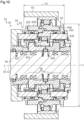
Fig. 3 is a cross-sectional view of the drive unit of the human-powered vehicle shown inFig. 2 taken along line 3-3. -
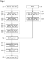
Fig. 4 is a block diagram showing a transmission path of human driving force and motor driving force in the human-powered vehicle shown inFig. 1 . -
Fig. 5 is a first table showing examples of configurations of the drive system for a human-powered vehicle and the drive unit for a human-powered vehicle shown inFig. 1 . -
Fig. 6 is a second table showing examples of configurations of the drive system for a human-powered vehicle and the drive unit for a human-powered vehicle shown inFig. 1 . -
Fig. 7 is a third table showing examples of configurations of the drive system for a human-powered vehicle and the drive unit for a human-powered vehicle shown inFig. 1 . -
Fig. 8 is a fourth table showing examples of configurations of the drive system for a human-powered vehicle and the drive unit for a human-powered vehicle shown inFig. 1 . -
Fig. 9 is a diagram showing a human-powered vehicle including a second embodiment of a drive system for a human-powered vehicle and a drive unit for a human-powered vehicle. -
Fig. 10 is a diagram showing a transmission device shown inFig. 9 . -
Fig. 11 is a diagram showing a human-powered vehicle including a third embodiment of a drive system for a human-powered vehicle and a drive unit for a human-powered vehicle. -
Fig. 12 is a diagram showing a human-powered vehicle including a fourth embodiment of a drive system for a human-powered vehicle and a drive unit for a human-powered vehicle. -
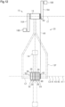
Fig. 13 is a side view showing a drive mechanism of a fifth embodiment of a human-powered vehicle including a drive system for a human-powered vehicle and a drive unit for a human-powered vehicle. -
Fig. 14 is a diagram of the human-powered vehicle shown inFig. 13 . -
Fig. 15 is a block diagram showing a transmission path of human driving force and motor driving force in a first modified example of a human-powered vehicle. -
Fig. 16 is a diagram showing a human-powered vehicle including a second modified example of a drive system for a human-powered vehicle and a drive unit for a human-powered vehicle. -
Fig. 17 is a diagram showing a human-powered vehicle including a third modified example of a drive system for a human-powered vehicle and a drive unit for a human-powered vehicle. -
Fig. 18 is a side view showing a drive mechanism of a human-powered vehicle including a fourth modified example of a drive system for a human-powered vehicle and a drive unit for a human-powered vehicle. -
Fig. 19 is a diagram showing a human-powered vehicle including a fifth modified example of a drive system for a human-powered vehicle and a drive unit for a human-powered vehicle. -
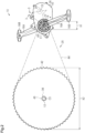
Fig. 20 is a side view showing a drive mechanism of a human-powered vehicle including a sixth modified example of a drive system for a human-powered vehicle and a drive unit for a human-powered vehicle. - A first embodiment of a
drive system 20 for a human-powered vehicle and adrive unit 50 for a human-powered vehicle will now be described with reference toFigs. 1 to 8 . - A human-powered
vehicle 10 is a vehicle including at least one wheel and driven by at least human driving force. The human-poweredvehicle 10 includes, for example, various types of bicycles such as a mountain bike, a road bike, a city bike, a cargo bike, a hand bike, and a recumbent bike. The number of wheels on the human-poweredvehicle 10 is not limited. The human-poweredvehicle 10 includes, for example, a unicycle and a vehicle including two or more wheels. The human-poweredvehicle 10 is not limited to a vehicle configured to be driven only by human driving force. The human-poweredvehicle 10 includes an E-bike that uses driving force of an electric motor in addition to human driving force for propulsion. The E-bike includes an electric assist bicycle that assists in propulsion with an electric motor. In the embodiments described below, the human-poweredvehicle 10 refers to a bicycle. - The human-powered
vehicle 10 includes anaxle 12 and awheel 14. Theaxle 12 is provided on aframe 10F of the human-poweredvehicle 10. Thewheel 14 is provided on theaxle 12 so as to rotate about theaxle 12 in accordance with human driving force. The human-poweredvehicle 10 includes acrank axle 16 rotatable relative to theframe 10F of the human-poweredvehicle 10. Two crankarms 16A are provided on respective axial ends of thecrank axle 16. Twopedals 16B are respectively coupled to the two crankarms 16A. Human driving force is input to thecrank axle 16 from thecrank arms 16A and thepedals 16B. - In an example, the
drive system 20 is for driving the human-poweredvehicle 10. In an example, thedrive system 20 includes at least a portion of a transmission path of human driving force in the human-poweredvehicle 10. In an example, thedrive system 20 includes the transmission path of human driving force from thecrank axle 16 to thewheel 14. In an example, thedrive system 20 includes thedrive unit 50 for a human-powered vehicle. In the present embodiment, thedrive unit 50 is disposed around thecrank axle 16. Thedrive unit 50 can be provided on theaxle 12 of thewheel 14. - In an example, the
drive system 20 includes arotation input unit 22, aspeed increaser 24, arotation output unit 26, and amotor 28. Therotation input unit 22 is configured to receive human driving force. In an example, therotation input unit 22 includes thecrank axle 16. Therotation output unit 26 is configured to receive human driving force via therotation input unit 22 and output human driving force to thewheel 14 of the human-poweredvehicle 10. In an example, therotation output unit 26 is connected to thewheel 14. In an example, therotation output unit 26 includes ahub shell 38. - The
speed increaser 24 is provided in the transmission path of human driving force. Thespeed increaser 24 is configured to receive human driving force. Thespeed increaser 24 is configured to receive human driving force via therotation input unit 22. - In an example, the
drive system 20 further includes atransmission device 30. Thetransmission device 30 is provided in the transmission path of human driving force. Thetransmission device 30 is configured to receive human driving force via therotation input unit 22. In an example, thetransmission device 30 is configured to shift a transmission ratio of the human-poweredvehicle 10. The transmission ratio is a ratio of speed of rotation output from thetransmission device 30 to speed of rotation input to thetransmission device 30. As the transmission ratio increases, the output rotational speed increases. - In this specification, a speed ratio R refers to a ratio of an output rotational speed S2 of a corresponding device to an input rotational speed S1 of the device. The speed ratio R is expressed by equation of "R = S2 / S1." The speed ratio R includes a transmission ratio, a speed-increasing ratio, a reduction ratio, and a motor reduction ratio. In a case where S1 = S2, the transmission ratio, the speed-increasing ratio, the reduction ratio, and the motor reduction ratio are 1. In a case where S1 < S2, the transmission ratio, the speed-increasing ratio, and the reduction ratio are greater than 1. In a case where
S 1 > S2, the transmission ratio, the speed-increasing ratio, the reduction ratio, and the motor reduction ratio are less than 1. In this specification, as the speed-increasing ratio increases, a speed-increasing degree increases. In this specification, as the reduction ratio increases, a reduction degree decreases. In this specification, as the motor reduction ratio increases, the reduction degree decreases. - In an example, the
drive system 20 further includes aspeed reducer 34. Thespeed reducer 34 is provided in the transmission path of human driving force. Thespeed reducer 34 is provided in the transmission path of human driving force between therotation input unit 22 and therotation output unit 26. - The
motor 28 is configured to apply propulsion force to the human-poweredvehicle 10. In an example, thedrive system 20 includes at least a portion of a transmission path of motor driving force of themotor 28. In an example, thedrive system 20 includes the transmission path of motor driving force from themotor 28 to thewheel 14. In an example, the transmission path of motor driving force joins with the transmission path of human driving force. The transmission path from where the transmission path of motor driving force joins with the transmission path of human driving force includes both the transmission path of human driving force and the transmission path of motor driving force. - In an example, the
drive system 20 further includes ahousing 36. In an example, at least one of the driving force transmission members of thedrive system 20 is provided in thehousing 36. In an example, thehousing 36 is a housing of thedrive unit 50. - In an example, the
drive system 20 includes thehub shell 38. Thehub shell 38 is formed separately from thehousing 36. In a case where thedrive unit 50 is provided on theaxle 12 of thewheel 14, thehub shell 38 can be formed integrally with thehousing 36. In an example, thedrive system 20 includes arear hub 46. In the present embodiment, thehub shell 38 is ahub shell 38 of therear hub 46. - In an example, the
drive system 20 includes a driverotation input unit 40, a driverotation output unit 42, and an endlessannular member 44. The driverotation input unit 40 is configured to receive human driving force. The driverotation output unit 42 is configured to output human driving force. The endlessannular member 44 couples the driverotation input unit 40 and the driverotation output unit 42. In an example, the driverotation input unit 40 includes one of a sprocket and a pulley. In an example, the driverotation output unit 42 includes one of a sprocket and a pulley. In an example, the endlessannular member 44 includes at least one of a chain and a belt. In the present embodiment, the driverotation input unit 40 includes a sprocket, the driverotation output unit 42 includes a sprocket, and the endlessannular member 44 includes a chain. In an example, the sprocket of the driverotation input unit 40 includes a front sprocket, and the sprocket of the driverotation output unit 42 includes a rear sprocket. - In the present embodiment, the
speed reducer 34 includes the driverotation input unit 40, the driverotation output unit 42, and the endlessannular member 44. The number of sprocket teeth of the driverotation input unit 40 is less than the number of sprocket teeth of the driverotation output unit 42. In an example the sprocket of the driverotation input unit 40 has nine teeth. In an example, the sprocket of the driverotation output unit 42 includes sixty teeth. - The
drive unit 50 includes at least one of the driving force transfer members of thedrive system 20. In an example, thedrive unit 50 includes thespeed increaser 24 and thetransmission device 30. In an example, thedrive unit 50 includes themotor 28 and amotor speed reducer 32. In an example, thedrive unit 50 further includes therotation input unit 22. In an example, thedrive unit 50 further includes thecrank axle 16 of the human-poweredvehicle 10. In an example, thedrive unit 50 further includes anet force unit 52. - The
drive unit 50 can further include thespeed reducer 34. In a case where thedrive unit 50 includes thespeed reducer 34, thespeed reducer 34 can include a first speed reducer including the driverotation input unit 40, the driverotation output unit 42, and the endlessannular member 44 and a second speed reducer differing from the first speed reducer. Thedrive unit 50 can include the second speed reducer. Thespeed reducer 34 can include the second speed reducer without including the first speed reducer. In a case where thespeed reducer 34 does not include the first speed reducer and includes the second speed reducer, the driverotation input unit 40, the driverotation output unit 42, and the endlessannular member 44 do not necessarily have to form thespeed reducer 34. In a case where thedrive unit 50 includes thespeed reducer 34, at least part of the driverotation input unit 40 can be provided on thedrive unit 50. - In an example, the
housing 36 is provided on theframe 10F of the human-poweredvehicle 10. In the present embodiment, thehousing 36 is configured to support aninput rotation shaft 54 that receives human driving force. In an example, human driving force is input to theinput rotation shaft 54. In the present embodiment, theinput rotation shaft 54 is thecrank axle 16. Theinput rotation shaft 54 is provided on thehousing 36 and is rotatable relative to thehousing 36 about an input center axis C1. In an example, the input center axis C1 is substantially coaxial with a rotational axis of theinput rotation shaft 54. In this specification, the description of "substantially coaxial" refers to being completely coaxial or being considered to be completely coaxial. The case of being considered to be completely coaxial is, for example, a case where not being coaxial has only a negligible effect on the functions of thedrive system 20 and thedrive unit 50. At least a portion of thecrank axle 16 is provided on thehousing 36. - In an example, the
rotation input unit 22, thespeed increaser 24, themotor 28, and thespeed reducer 34 are provided on thehousing 36. In the present embodiment, at least a portion of therotation input unit 22, thespeed increaser 24, thetransmission device 30, themotor 28, and themotor speed reducer 32 are provided in an inner cavity of thehousing 36. In the present embodiment, at least part of thespeed reducer 34 is provided on thehousing 36. - The
rotation input unit 22 is configured to be rotatable about the input center axis C1. In an example, therotation input unit 22 is provided on thehousing 36 and is rotatable relative to thehousing 36 about the input center axis C1. In the present embodiment, therotation input unit 22 includes theinput rotation shaft 54. In an example, therotation input unit 22 includes aninput transfer portion 22A connecting thecrank axle 16 and thespeed increaser 24. - For example, the
drive unit 50 includes a first one-way clutch 22B. In an example, the first one-way clutch 22B is provided between therotation input unit 22 and theinput transfer portion 22A. The first one-way clutch 22B transmits rotational torque from thecrank axle 16 to therotation input unit 22 in a case where thecrank axle 16 is rotated in a direction in which the human-poweredvehicle 10 moves forward, and restricts transmission of rotational torque from therotation input unit 22 to thecrank axle 16 in a case where therotation input unit 22 is rotated in a direction in which the human-poweredvehicle 10 moves forward. In an example, the first one-way clutch 22B includes at least one of a roller clutch and a pawl-type clutch. In an example, the first one-way clutch 22B includes an inner ring and an outer ring. The inner ring can be formed integrally with therotation input unit 22. Alternatively, the inner ring can be formed separately from therotation input unit 22 and coupled to therotation input unit 22 so as to rotate integrally with therotation input unit 22. In a case where the inner ring is formed separately from therotation input unit 22, the inner ring is coupled to therotation input unit 22 by, for example, a spline. The outer ring can be formed integrally with theinput transfer portion 22A. Alternatively, the outer ring can be formed separately from theinput transfer portion 22A and coupled to theinput transfer portion 22A so as to rotate integrally with theinput transfer portion 22A. In a case where the outer ring is formed separately from theinput transfer portion 22A, the outer ring is coupled to theinput transfer portion 22A by, for example, a spline. - The
transmission device 30 is configured to receive human driving force via theinput rotation shaft 54. In an example, thetransmission device 30 is configured to receive human driving force via thespeed increaser 24. In an example, thetransmission device 30 is configured to output human driving force to thespeed reducer 34. - The
speed reducer 34 is configured to receive human driving force via thespeed increaser 24. Thespeed reducer 34 is configured to receive human driving force via thetransmission device 30. - The
rotation input unit 22, thespeed increaser 24, thetransmission device 30, thenet force unit 52, thespeed reducer 34, and therotation output unit 26 form a portion of the transmission path of human driving force. In the present embodiment, human driving force is sequentially transmitted through therotation input unit 22, thespeed increaser 24, thetransmission device 30, thespeed reducer 34, and therotation output unit 26. Themotor speed reducer 32, thenet force unit 52, thespeed reducer 34, and therotation output unit 26 form a portion of the transmission path of motor driving force. In the present embodiment, motor driving force is transmitted to a location between thetransmission device 30 and thespeed reducer 34. In the present embodiment, themotor 28 is configured to output motor driving force to thenet force unit 52 in the transmission path of human driving force. - In an example, the
speed increaser 24 is provided on thehousing 36. In an example, thespeed increaser 24 includes at least one of a gear, a pulley, and an endless annular member. In the present embodiment, thespeed increaser 24 includes a gear. In an example, thespeed increaser 24 includes aplanetary gear mechanism 24X. Thespeed increaser 24 can include gears each having a different rotational center axis in addition to or instead of theplanetary gear mechanism 24X. In a case where thespeed increaser 24 includes a pulley, thespeed increaser 24 can include a belt-type speed-increasing mechanism. In a case where thespeed increaser 24 includes an endless annular member, thespeed increaser 24 can include a chain-type speed increasing mechanism. - The
speed increaser 24 includes a speed increaser rotational center axis A1, a speed increaserrotation input unit 24A, and a speed increaserrotation output unit 24B. The speed increaserrotation input unit 24A is configured to receive human driving force. The speed increaserrotation output unit 24B is configured to output human driving force. The speed increaserrotation input unit 24A is rotatable about the speed increaser rotational center axis A1. The speed increaserrotation output unit 24B is rotatable about the speed increaser rotational center axis A1. In the present embodiment, the speed increaser rotational center axis A1 is substantially coaxial with the input center axis C1. The speed increaserrotation input unit 24A includes a speed increaser input rotational axis A2. The speed increaserrotation output unit 24B includes a speed increaser output rotational axis A3. The speed increaser output rotational axis A3 is coaxial with the speed increaser input rotational axis A2. In the present embodiment, the speed increaser input rotational axis A2 and the speed increaser output rotational axis A3 are substantially coaxial with the speed increaser rotational center axis A1. Thespeed increaser 24 is configured to increase rotational speed of the speed increaserrotation input unit 24A in accordance with the speed-increasing ratio and output the rotation from the speed increaserrotation output unit 24B. - In an example, the speed-increasing ratio of the
speed increaser 24 is a ratio of rotational speed of the speed increaserrotation output unit 24B to rotational speed of the speed increaserrotation input unit 24A. As the speed-increasing ratio of thespeed increaser 24 increases, a speed-increasing degree of thespeed increaser 24 increases. - In an example, the speed-increasing ratio of the
speed increaser 24 is greater than or equal to 3 and less than or equal to 20. In an example, the speed-increasing ratio of thespeed increaser 24 is greater than or equal to 5 and less than or equal to 18. In an example, the speed-increasing ratio of thespeed increaser 24 is greater than or equal to 7 and less than or equal to 16. In an example, the speed-increasing ratio of thespeed increaser 24 is greater than or equal to 9 and less than or equal to 14. In an example, the speed-increasing ratio of thespeed increaser 24 is 9.4. - The speed-increasing ratio of the
speed increaser 24 can be greater than or equal to 3 and less than or equal to 11. The speed-increasing ratio of thespeed increaser 24 can be greater than or equal to 6 and less than or equal to 20. In an example, the speed-increasing ratio of thespeed increaser 24 is 6.032. - In an example, the
transmission device 30 is provided on thehousing 36. Thetransmission device 30 includes a transmission device rotational center axis A4, a transmission devicerotation input unit 30A, and a transmission devicerotation output unit 30B. The transmission devicerotation input unit 30A is rotatable about the transmission device rotational center axis A4. The transmission devicerotation output unit 30B is rotatable about the transmission device rotational center axis A4. The transmission device rotational center axis A4 is substantially coaxial with the input center axis C1. Thetransmission device 30 is configured to change the speed of rotation received from the transmission devicerotation input unit 30A and output the rotation from the transmission devicerotation output unit 30B in accordance with the transmission ratio of thetransmission device 30. The transmission devicerotation output unit 30B is configured to output human driving force to thenet force unit 52. - In an example, the
transmission device 30 includes a transmissiondevice input unit 30C and a transmissiondevice output unit 30D. In an example, the transmissiondevice input unit 30C is configured to receive human driving force. In an example, the transmissiondevice output unit 30D is configured to output human driving force. In an example, the transmissiondevice input unit 30C includes the transmission devicerotation input unit 30A, and the transmissiondevice output unit 30D includes the transmission devicerotation output unit 30B. - In an example, the transmission ratio of the
transmission device 30 is a ratio of rotational speed of the transmissiondevice output unit 30D to rotational speed of the transmissiondevice input unit 30C. In an example, the transmission ratio of thetransmission device 30 is a ratio of rotational speed of the transmission devicerotation output unit 30B to rotational speed of the transmission devicerotation input unit 30A. In an example, thetransmission device 30 is configured to shift the transmission ratio within a range from a minimum transmission ratio to a maximum transmission ratio. The minimum transmission ratio is a transmission ratio corresponding to a speed decrease. The maximum transmission ratio is a transmission ratio corresponding to a speed increase. In an example, the minimum transmission ratio is greater than 0 and less than 1. As the minimum transmission ratio decreases, the speed-increasing degree becomes smaller in a case where the transmission ratio is the minimum transmission ratio. In an example, the maximum transmission ratio is greater than 1 and less than or equal to 5. As the maximum transmission ratio increases, the speed-increasing degree becomes larger in a case where the transmission ratio is the maximum transmission ratio. - In the present embodiment, the
transmission device 30 is configured to shift the transmission ratio in a stepped manner. In an example, thetransmission device 30 includes multiple transmission stages. In an example, the transmission stages each have a different transmission ratio. The transmission stage is changed from one to another one of the transmission stages to shift the transmission ratio of thetransmission device 30. In an example, thetransmission device 30 includes aplanetary gear mechanism 30X. Thetransmission device 30 can include a manual transmission device including a clutch plate instead of or in addition to theplanetary gear mechanism 30X. Thetransmission device 30 can be configured to shift the transmission ratio in a stepless manner. In a case where the transmission ratio is shifted in a stepless manner, thetransmission device 30 includes a continuously variable transmission (CVT). In an example, thetransmission device 30 includes a transmission switch 30Y configured to shift the transmission ratio of thetransmission device 30. The transmission switch 30Y can be controlled by an electric actuator or can be controlled by a mechanical cable connected to a shifter operable by a rider. An example of thetransmission device 30 is the transmission device disclosed inJapanese Laid-Open Patent Publication No. 2016-78618 transmission device 30 includes multiple transmission stages, various types of transmission devices such as a planetary gear type transmission, a ball type continuously variable transmission, and a parallel-axis gear transmission can be used. The transmission device is not limited to a particular type. - In an example, the ratio of the maximum transmission ratio of the transmission ratios of the transmission stages to the minimum transmission ratio of the transmission ratios of the transmission stages is 1.2 or greater and 8 or less. In an example, the ratio of the maximum transmission ratio to the minimum transmission ratio is 1.7 or greater and 7 or less. In an example, the ratio of the maximum transmission ratio to the minimum transmission ratio is 2.4 or greater and 6 or less. In an example, the ratio of the maximum transmission ratio to the minimum transmission ratio is 2.4.
- In an example, the
planetary gear mechanism 30X is configured to shift the transmission ratio in three or more steps. In an example, the transmission stages include three or more transmission stages. In an example, the three or more transmission stages each have a different transmission ratio. - In an example, the transmission stages includes a first transmission stage and a second transmission stage. In an example, the transmission ratio of the first transmission stage is a first ratio. In an example, the transmission ratio of the second transmission stage is a second ratio. In an example, the second ratio is one of the transmission ratios of the transmission stages that is greater than the first ratio and closest to the first ratio. In an example, the first transmission stage and the second transmission stage correspond to any two transmission stages of the transmission stages that satisfy a condition. The first transmission stage corresponds to one of the transmission stages differing from the transmission stage having the largest transmission ratio. The second transmission stage corresponds to one of the transmission stages having a transmission ratio that is greater than the transmission ratio of the first transmission stage and is closest to the transmission ratio of the first transmission stage. In an example, the ratio of the first ratio to the second ratio is greater than or equal to 0.75 and less than 1. In an example, the ratio of the first ratio to the second ratio is greater than or equal to 0.8 and less than 1. In an example, the ratio of the first ratio to the second ratio is greater than or equal to 0.85 and less than 1. In an example, the ratio of the first ratio to the second ratio is 0.85.
- The
motor 28 is configured to input motor driving force to thespeed reducer 34. Themotor 28 is configured to output motor driving force to a location between thespeed increaser 24 and thespeed reducer 34 in the transmission path of human driving force. In an example, themotor 28 is configured to output motor driving force to a location downstream of thespeed increaser 24 in the transmission path of human driving force. In an example, themotor 28 is configured to output motor driving force to a location between thespeed increaser 24 and therotation output unit 26 in the transmission path of human driving force. - The
motor 28 is provided on thehousing 36. Themotor 28 includes a motor rotational axis A5. A motorrotational shaft 28A is provided on thehousing 36 and is rotatable about an additional center axis C2. In an example, the additional center axis C2 is parallel to the input center axis C1 and differs from the input center axis C1. In an example, the additional center axis C2 extends through the inner cavity of thehousing 36 and is parallel to the input center axis C1. In an example, the motor rotational axis A5 is substantially coaxial with the additional center axis C2. - The
motor speed reducer 32 is configured to output motor driving force received from themotor 28 to the transmission path of human driving force. In an example, themotor speed reducer 32 includes at least one of a gear, a pulley, and an endless annular member. In the present embodiment, themotor speed reducer 32 includes a gear. In an example, themotor speed reducer 32 includes a motor speed-reducingmechanism 32X including spur gears each having a different pitch diameter. The spur gears of the motor speed-reducingmechanism 32X connect the motorrotational shaft 28A and thenet force unit 52. In a case where themotor speed reducer 32 includes a gear, themotor speed reducer 32 can include a planetary gear mechanism. In a case where themotor speed reducer 32 includes a pulley, themotor speed reducer 32 can include a belt-type speed-reducing mechanism. In a case where themotor speed reducer 32 includes an endless annular member, themotor speed reducer 32 can include a chain-type speed-reducing mechanism. - In an example, the
motor speed reducer 32 includes a motor speed reducerrotation input unit 32A and a motor speed reducerrotation output unit 32B. In an example, the motor reduction ratio of themotor speed reducer 32 is the ratio of rotational speed of the motor speed reducerrotation output unit 32B to rotational speed of the motor speed reducerrotation input unit 32A. In an example, the motor reduction ratio of themotor speed reducer 32 is 0.125 or greater and less than 1. In an example, the motor reduction ratio of themotor speed reducer 32 is 0.15 or greater and less than 0.7. In an example, the motor reduction ratio of themotor speed reducer 32 is 0.17 or greater and less than 0.5. In an example, the motor reduction ratio of themotor speed reducer 32 is 0.2 or greater and less than 0.3. In an example, the motor reduction ratio of themotor speed reducer 32 is 0.25. - The
net force unit 52 is provided in the transmission path of human driving force between therotation input unit 22 and therotation output unit 26. Thenet force unit 52 is configured to receive motor driving force from themotor 28 and human driving force. In an example, thenet force unit 52 is configured to add motor driving force from themotor 28 and human driving force and outputs the net force to thespeed reducer 34. In an example, thenet force unit 52 is configured to receive human driving force from the transmission devicerotation output unit 30B and output the human driving force to thespeed reducer 34. In an example, thenet force unit 52 is configured to receive motor driving force from the motor speed reducerrotation output unit 32B and output the motor driving force to thespeed reducer 34. - In an example, the
drive unit 50 includes a second one-way clutch 52A. In an example, the second one-way clutch 52A is provided in the transmission path of motor driving force between themotor 28 and thenet force unit 52. In an example, the second one-way clutch 52A is configured to transmit rotational force of themotor 28 to thenet force unit 52 and restrict transmission of rotational force of thenet force unit 52 to themotor 28. In an example, the second one-way clutch 52A includes at least one of a roller clutch and a pawl-type clutch. - The
speed reducer 34 is configured to receive motor driving force from themotor 28 and human driving force. Thespeed reducer 34 receives the motor driving force and the human driving force via thenet force unit 52. Thespeed reducer 34 receives the motor driving force from themotor 28 via themotor speed reducer 32. - In an example, the
speed reducer 34 includes a first speed reducer center axis A7, a speed reducerrotation input unit 34A, a second speed reducer center axis A8, and a speed reducerrotation output unit 34B. In an example, the second speed reducer center axis A8 differs from the first speed reducer center axis A7. In an example, the speed reducerrotation input unit 34A is rotatable about the first speed reducer center axis A7. In an example, the speed reducerrotation output unit 34B is rotatable about the second speed reducer center axis A8. The first speed reducer center axis A7 is substantially coaxial with the input center axis C1. The second speed reducer center axis A8 is substantially coaxial with a rotational center axis C3 of thehub shell 38. In an example, human driving force is input to the speed reducerrotation input unit 34A. In an example, the human driving force is output from the speed reducerrotation output unit 34B. Thespeed reducer 34 is configured to reduce the speed of rotation that is input to the speed reducerrotation input unit 34A in accordance with the reduction ratio and output the rotation from the speed reducerrotation output unit 34B. - In an example, the reduction ratio of the
speed reducer 34 is a ratio of rotational speed of the speed reducerrotation output unit 34B to rotational speed of the speed reducerrotation input unit 34A. In a first example of the reduction ratio, the reduction ratio of thespeed reducer 34 is greater than 0 and 0.8 or less. The reduction ratio of thespeed reducer 34 is, for example, 0.1 or greater and 0.5 or less. The reduction ratio of thespeed reducer 34 is, for example, 0.15 or greater and 0.3 or less. The reduction ratio of thespeed reducer 34 is, for example, 0.15. - In a second example of the reduction ratio, the reduction ratio of the
speed reducer 34 is greater than 0 and less than 1. The reduction ratio of thespeed reducer 34 is, for example, 0.125 or greater and less than 0.7. The reduction ratio of thespeed reducer 34 is, for example, 0.17 or greater and less than 0.5. The reduction ratio of thespeed reducer 34 is, for example, 0.2 or greater and less than 0.3. - In a third example of the reduction ratio, the reduction ratio of the
speed reducer 34 is 0.05 or greater and 0.5 or less. The reduction ratio of thespeed reducer 34 is, for example, 0.1 or greater and 0.2 or less. - In a fourth example of the reduction ratio, the reduction ratio of the
speed reducer 34 is greater than 0 and 0.65 or less. The reduction ratio of thespeed reducer 34 is, for example, 0.05 or greater and 0.5 or less. The reduction ratio of thespeed reducer 34 is, for example, 0.1 or greater and 0.3 or less. - In an example, the drive
rotation input unit 40 is configured to receive human driving force via thespeed increaser 24. In an example, the driverotation input unit 40 receives human driving force via thetransmission device 30. In an example, the driverotation input unit 40 receives motor driving force from themotor 28. In an example, the driverotation input unit 40 is configured to be rotatable about a first drive rotational center axis A9. The first drive rotational center axis A9 is substantially coaxial with the input center axis C1. In an example, the first drive rotational center axis A9 is substantially coaxial with the speed increaser rotational center axis A1. In an example, the first drive rotational center axis A9 is substantially coaxial with the transmission device rotational center axis A4. The first drive rotational center axis A9 is substantially coaxial with the first speed reducer center axis A7. - In an example, the drive
rotation output unit 42 is configured to be rotatable about a second drive rotational center axis A10. In an example, the second drive rotational center axis A10 differs from the first drive rotational center axis A9. In an example, the second drive rotational center axis A10 is parallel to the first drive rotational center axis A9. In an example, the second drive rotational center axis A10 is substantially coaxial with the rotational center axis C3 of theaxle 12 of thewheel 14 of the human-poweredvehicle 10. The second drive rotational center axis A10 is substantially coaxial with the second speed reducer center axis A8. - The drive
rotation input unit 40 has a single pitch circle configured to receive human driving force via theinput rotation shaft 54, which is configured to receive human driving force. The driverotation output unit 42 has a single pitch circle configured to output human driving force to thewheel 14 of the human-poweredvehicle 10. The pitch circle of the driverotation input unit 40 has an input pitch diameter X1. The pitch circle of the driverotation output unit 42 has an output pitch diameter X2. The input pitch diameter X1 is smaller than the output pitch diameter X2. In an example, the reduction ratio of thespeed reducer 34 is a ratio of the input pitch diameter X1 to the output pitch diameter X2. In an example, the driverotation input unit 40, the driverotation output unit 42, and the endlessannular member 44 form thespeed reducer 34. In an example, the driverotation input unit 40 includes the speed reducerrotation input unit 34A. In an example, the driverotation output unit 42 includes the speed reducerrotation output unit 34B. - In an example, the input pitch diameter X1 is 10 mm or greater and 103 mm or less. In an example, the input pitch diameter X1 is 15 mm or greater and 82 mm or less. In an example, the input pitch diameter X1 is 20 mm or greater and 62 mm or less. In an example, the input pitch diameter X1 is 25 mm or greater and 38 mm or less. In an example, the input pitch diameter X1 is 38 mm.
- In an example, the pitch circle ratio of the input pitch diameter X1 of the drive
rotation input unit 40 to the output pitch diameter X2 of the driverotation output unit 42 is greater than 0 and 1 or less. The pitch circle ratio of the input pitch diameter X1 to the output pitch diameter X2 is, for example, 0.05 or greater and 0.8 or less. The pitch circle ratio of the input pitch diameter X1 to the output pitch diameter X2 is, for example, 0.1 or greater and 0.5 or less. The pitch circle ratio of the input pitch diameter X1 to the output pitch diameter X2 is, for example, 0.15 or greater and 0.2 or less. The pitch circle ratio of the input pitch diameter X1 to the output pitch diameter X2 is, for example, 0.2. - The
rotation output unit 26 is connected to thewheel 14 and is configured to output human driving force, received from thespeed reducer 34, to thewheel 14. Therotation output unit 26 is configured to receive human driving force via thespeed increaser 24. Therotation output unit 26 is configured to receive human driving force and motor driving force from thespeed reducer 34 via the driverotation output unit 42. The human driving force and the motor driving force, which are received from the driverotation output unit 42, rotate thehub shell 38 of therotation output unit 26, thereby drive the human-poweredvehicle 10. - In an example, at least one of the
speed increaser 24, thetransmission device 30, and thespeed reducer 34 includes a metal material. In an example, at least one of thespeed increaser 24, thetransmission device 30, and thespeed reducer 34 includes a component forming the transmission path of human driving force, and at least a portion of the component includes a metal material. In an example, the metal material includes at least one of steel, a stainless steel alloy, an aluminum alloy, a magnesium alloy, a titanium alloy, and iron and steel. - In an example, at least one of the
speed increaser 24, thetransmission device 30, and thespeed reducer 34 includes a resin material. In an example, at least one of thespeed increaser 24, thetransmission device 30, and thespeed reducer 34 includes a component forming the transmission path of human driving force, and at least a portion of the component includes a resin material. In an example, the resin material includes a thermoplastic member and a thermosetting member. The thermoplastic member includes at least one of polyethylene, polypropylene, polystyrene, AS resin, ABS resin, polyvinyl chloride, acrylic resin, PET resin, PVA resin, polyvinylidene chloride, polyvinylidene fluoride nylon 6,nylon 66,nylon 12, acetal resin, polycarbonate, PBT resin, polyphenylene sulfide, polyimide resin, polyetherimide, polyphenylene sulfide, polytetrafluoroethylene, polychlorotrifluoroethylene, polyamide-imide, acetyl cellulose, nitro cellulose, propionic acid cellulose, and ethyl cellulose. The thermosetting member includes at least one of a phenol resin, a urea resin, a melamine resin, an unsaturated polyester, a polyurethane, an allyl resin, a silicon resin, an epoxy resin, and a furan resin. - In an example, at least one of the
speed increaser 24, thetransmission device 30, and thespeed reducer 34 can include a gear including tooth tips formed from a resin material, and the remaining portion of the gear can be formed from a metal material. In an example, at least one of thespeed increaser 24, thetransmission device 30, and thespeed reducer 34 can include a gear formed from a resin material. In an example, at least one of thespeed increaser 24, thetransmission device 30, and thespeed reducer 34 can include a gear formed from a metal material. - In the present embodiment, human driving force is sequentially transmitted through the
rotation input unit 22, thespeed increaser 24, thetransmission device 30, thespeed reducer 34, and therotation output unit 26, and motor driving force is transmitted to a location between thetransmission device 30 and thespeed reducer 34. However, at least one of the layout and the structure of each of thespeed increaser 24, thetransmission device 30, themotor 28, themotor speed reducer 32, and thespeed reducer 34 can be changed. - Tables shown in
Figs. 5 to 8 show first to fiftieth examples of combinations of thespeed increaser 24, thetransmission device 30, themotor 28, themotor speed reducer 32, and thespeed reducer 34. Thedrive system 20 shown inFigs. 1 to 4 corresponds to the first example. - In
Figs. 5 to 8 , the layout location indicates the location of the rotational center axis of each of thespeed increaser 24, thetransmission device 30, themotor 28, themotor speed reducer 32, and thespeed reducer 34. In each example, thespeed increaser 24, thetransmission device 30, themotor 28, themotor speed reducer 32, and thespeed reducer 34 are arranged so that each rotational center axis conforms to the axis indicated in the layout location. In the tables shown inFigs. 5 to 8 , the layout location that is indicated by "-" indicates that thedrive system 20 does not include the corresponding one of thespeed increaser 24, thetransmission device 30, themotor 28, themotor speed reducer 32, and thespeed reducer 34 indicated by "-" in the layout location. - A first axis B1 is substantially coaxial with the input center axis C1. A second axis B2 is substantially coaxial with the additional center axis C2. A third axis B3 is substantially coaxial with the rotational center axis C3. A fourth axis B4 corresponds to, for example, a case where the rotational center axis of the
rotation input unit 22 differs from the rotational center axis of therotation output unit 26 in each of thespeed increaser 24 and thespeed reducer 34. In a case where the layout location of thespeed reducer 34 is the fourth axis B4, thespeed reducer 34 includes the driverotation input unit 40 and the driverotation output unit 42. In a case where the layout location of thespeed increaser 24 is the fourth axis B4, thespeed increaser 24 includes the driverotation input unit 40 and the driverotation output unit 42. In a case where thespeed increaser 24 includes the driverotation input unit 40 and the driverotation output unit 42, the number of sprocket teeth of the driverotation input unit 40 is greater than the number of sprocket teeth of the driverotation output unit 42. - In a case where the layout location of each of the
speed increaser 24, thetransmission device 30, themotor 28, themotor speed reducer 32, and thespeed reducer 34 is thefirst axis B 1 or the second axis B2, each of thespeed increaser 24, thetransmission device 30, themotor 28, themotor speed reducer 32, and thespeed reducer 34 is provided in the vicinity of thecrank axle 16. In a case where the layout location of each of thespeed increaser 24, thetransmission device 30, themotor 28, themotor speed reducer 32, and thespeed reducer 34 is the third axis B3, each of thespeed increaser 24, thetransmission device 30, themotor 28, themotor speed reducer 32, and thespeed reducer 34 is provided on therear hub 46. - In the tables shown in
Figs. 5 to 8 , the transmission type includes a planetary gear type, a chain type, a CVT type, an external transmission type, and a gear type. In a case where the transmission type of each of thespeed increaser 24, thetransmission device 30, themotor 28, themotor speed reducer 32, and thespeed reducer 34 is a planetary gear, thespeed increaser 24, thetransmission device 30, themotor 28, themotor speed reducer 32, and thespeed reducer 34 each include a planetary gear mechanism. In a case where the transmission type of each of thespeed increaser 24, thetransmission device 30, themotor 28, themotor speed reducer 32, and thespeed reducer 34 is a chain, thespeed increaser 24, thetransmission device 30, themotor 28, themotor speed reducer 32, and thespeed reducer 34 each include two sprockets and a chain. In a case where the transmission type of each of thespeed increaser 24, thetransmission device 30, themotor 28, themotor speed reducer 32, and thespeed reducer 34 is a chain, thespeed increaser 24, thetransmission device 30, themotor 28, themotor speed reducer 32, and thespeed reducer 34 can each include two pulleys and a belt. In a case where the transmission type of thetransmission device 30 is CVT, thetransmission device 30 includes a CVT. In a case where the transmission type of thetransmission device 30 is an external transmission, thetransmission device 30 includes an external transmission device. In a case where the transmission type of themotor speed reducer 32 is a gear, themotor speed reducer 32 includes gears. In the tables shown inFigs. 5 to 8 , in each example in which the transmission type of thetransmission device 30 is described as external transmission and CVT, thetransmission device 30 includes at least one of an external transmission device and a CVT. In the tables shown inFigs. 5 to 8 , in each example in which the transmission type of thetransmission device 30 is described as external transmission and CVT, thetransmission device 30 can include a planetary gear mechanism in addition to or instead of at least one of an external transmission device and a CVT. In the tables shown inFigs. 5 to 8 , in each example in which the transmission type of thespeed increaser 24 is described as planetary gear and chain, thespeed increaser 24 includes at least one of a planetary gear and a chain. In the tables shown inFigs. 5 to 8 , in each example in which the transmission type of thespeed increaser 24 is described as planetary gear and chain, thespeed increaser 24 can include gears in addition to or instead of at least one of a planetary gear and a chain. - A second embodiment of the
drive system 20 and thedrive unit 50 will now be described with reference toFigs. 4 ,9 , and10 . Thedrive system 20 and thedrive unit 50 of the second embodiment are the same as thedrive system 20 and thedrive unit 50 of the first embodiment except for the structure of thedrive unit 50. In the second embodiment, same reference characters are given to those components that are the same as the corresponding components of the first embodiment. Such components will not be described in detail. - The
drive system 20 of the present embodiment corresponds to, for example, the thirty-first to thirty-sixth examples shown inFig. 7 . In the present embodiment, thedrive unit 50 includes anadditional shaft 56. The center axis of theadditional shaft 56 is substantially coaxial with the additional center axis C2. In the present embodiment, thespeed increaser 24 includes gears. In the present embodiment, the speed increaserrotation input unit 24A is configured to be rotatable about the input center axis C1. In the present embodiment, the speed increaserrotation output unit 24B is configured to be rotatable about the additional center axis C2. In the present embodiment, thetransmission device 30 is provided on theadditional shaft 56 so that the transmission device rotational center axis A4 is substantially coaxial with the additional center axis C2. In an example, a speed reducer and a speed increaser are not provided between thetransmission device 30 and thenet force unit 52. In the present embodiment, themotor 28 is provided on thehousing 36 so that the motor rotational axis A5 is substantially coaxial with the input center axis C1. In the present embodiment, themotor speed reducer 32 is provided on thehousing 36 so that a motor speed reducer center axis A6 is substantially coaxial with the input center axis C1. - In the present embodiment, the
transmission device 30 includes, for example, aplanetary gear mechanism 58. In an example, thetransmission device 30 includes gears. In an example, thetransmission device 30 includes theplanetary gear mechanism 58 including gears. In an example, the gears at least partially include a resin member. The resin member includes a resin material. In an example, one of the gears includes tooth tips including a resin material. In an example, the resin member includes at least one of a thermoplastic member and a thermosetting member. One of the gears includes tooth tips including the thermoplastic member. One of the gears can include tooth tips including the thermosetting member. - The
planetary gear mechanism 58 is configured to output rotational force to a transmissiondevice output unit 60 of thetransmission device 30. In an example, the transmissiondevice output unit 60 is tubular. In an example, at least a portion of theplanetary gear mechanism 58 is provided in the inner cavity of the transmissiondevice output unit 60. The transmissiondevice output unit 60 is connected to thenet force unit 52 so as to output rotational force to thenet force unit 52. In an example, thetransmission device 30 includes a firstplanetary assembly 62 and a secondplanetary assembly 64. In an example, theplanetary gear mechanism 58 includes the firstplanetary assembly 62 and the secondplanetary assembly 64 The secondplanetary assembly 64 is connected to the firstplanetary assembly 62. In an example, the secondplanetary assembly 64 is located at a position separated from the firstplanetary assembly 62 in a direction parallel to the transmission device rotational center axis A4. In an example, the firstplanetary assembly 62 and the secondplanetary assembly 64 share a common transmission device rotational center axis. The common transmission device rotational center axis of the firstplanetary assembly 62 and the secondplanetary assembly 64 is substantially coaxial with the transmission device rotational center axis A4. - The first
planetary assembly 62 includes afirst sun gear 62A, afirst ring gear 62B, firstplanetary gears 62C, and afirst carrier 62D. Thefirst sun gear 62A is disposed around theadditional shaft 56. Thefirst ring gear 62B is disposed around thefirst sun gear 62A. The firstplanetary gears 62C are disposed between thefirst sun gear 62A and thefirst ring gear 62B to engage with thefirst sun gear 62A and thefirst ring gear 62B. Thefirst carrier 62D is connected to the firstplanetary gear 62C. - The second
planetary assembly 64 includes asecond sun gear 64A, asecond ring gear 64B, secondplanetary gears 64C, and asecond carrier 64D. Thesecond sun gear 64A is disposed around theadditional shaft 56. Thesecond ring gear 64B is disposed around thesecond sun gear 64A. The secondplanetary gears 64C are arranged between thesecond sun gear 64A and thesecond ring gear 64B to engage with thesecond sun gear 64A and thesecond ring gear 64B. Thesecond carrier 64D is connected to the secondplanetary gears 64C. - In an example, the transmission device
rotation input unit 30A is connected to thefirst carrier 62D of the firstplanetary assembly 62. In an example, the transmission devicerotation output unit 30B is connected to the transmissiondevice output unit 60. The transmissiondevice output unit 60 rotates integrally with thesecond ring gear 64B of the secondplanetary assembly 64. Thetransmission device 30 includes at least four transmission stages. In an example, thetransmission device 30 includes four transmission stages. In an example, thetransmission device 30 includes atransmission switch 66. In an example, thetransmission switch 66 includes four clutches. Thetransmission switch 66 is configured to switch the four clutches to switch the transmission stage of thetransmission device 30. - The
transmission device 30 has a maximum dimension Y1 of, for example, 80 mm or less in a direction orthogonal to the transmission device rotational center axis A4. Thetransmission device 30 has a maximum dimension Y2 of, for example, 30 mm or less in a direction parallel to the transmission device rotational center axis A4. The maximum dimension Y1 is a dimension between a farthest part of the secondplanetary gears 64C from the transmission device rotational center axis A4 and another farthest part of the secondplanetary gears 64C from the transmission device rotational center axis A4 located at the opposite side in the circumferential direction of the transmission device rotational center axis A4. The maximum dimension Y2 is a dimension between an end of the firstplanetary gear 62C opposite to the secondplanetary assembly 64 and an end of the secondplanetary gears 64C opposite to the firstplanetary assembly 62 in a direction parallel to the transmission device rotational center axis A4. The maximum dimension Y2 can be a dimension between an end of thefirst carrier 62D opposite to the secondplanetary assembly 64 and an end of thesecond carrier 64D opposite to the firstplanetary assembly 62 in a direction parallel to the transmission device rotational center axis A4. - The maximum dimension Y1 of the
transmission device 30 is, for example, 70 mm or less in a direction orthogonal to the transmission device rotational center axis A4. The maximum dimension Y1 of thetransmission device 30 is, for example, 60 mm or less in a direction orthogonal to the transmission device rotational center axis A4. The maximum dimension Y2 is, for example, 20 mm or less in a direction parallel to the transmission device rotational center axis A4. The maximum dimension Y2 is, for example, 10 mm or less in a direction parallel to the transmission device rotational center axis A4. The maximum dimension Y2 is, for example, 6 mm or less in a direction parallel to the transmission device rotational center axis A4. - A third embodiment of the
drive system 20 and thedrive unit 50 will now be described with reference toFigs. 4 and11 . Thedrive system 20 and thedrive unit 50 of the third embodiment are the same as thedrive system 20 and thedrive unit 50 of the first embodiment except for the structure of thedrive unit 50. In the third embodiment, same reference characters are given to those components that are the same as the corresponding components of the first embodiment. Such components will not be described in detail. - The
drive system 20 of the present embodiment corresponds to, for example, the ninth to eleventh examples shown inFig. 5 . In the present embodiment, thedrive unit 50 includes thehousing 36, thespeed increaser 24, thetransmission device 30, and themotor 28. In the present embodiment, thespeed increaser 24, thetransmission device 30, and themotor 28 are provided on thehousing 36. Thespeed increaser 24, thetransmission device 30, and themotor 28 are disposed around thecrank axle 16. In the present embodiment, thespeed increaser 24 and thetransmission device 30 each include at least one planetary gear mechanism disposed around thecrank axle 16. - In the present embodiment, the
drive unit 50 includes themotor speed reducer 32. In the present embodiment, themotor speed reducer 32 is provided on thehousing 36. Themotor speed reducer 32 is disposed around thecrank axle 16. In the present embodiment, themotor speed reducer 32 includes at least one planetary gear mechanism disposed around thecrank axle 16. In an example, themotor speed reducer 32 includes the motor speed reducer center axis A6, the motor speed reducerrotation input unit 32A, and the motor speed reducerrotation output unit 32B. In the present embodiment, the motor speed reducerrotation input unit 32A is, for example, rotatable about the motor speed reducer center axis A6. In the present embodiment, the motor speed reducerrotation output unit 32B is, for example, rotatable about the motor speed reducer center axis A6. The motor speed reducer center axis A6 is substantially coaxial with the input center axis C1. - In the present embodiment, the speed increaser rotational center axis A1, the transmission device rotational center axis A4, and the motor rotational axis A5 are substantially coaxial with each other. In an example, the speed increaser rotational center axis A1, the transmission device rotational center axis A4, and the motor rotational axis A5 are substantially coaxial with the input center axis C1. In an example, at least one of the speed increaser rotational center axis A1, the transmission device rotational center axis A4, and the motor rotational axis A5 is substantially coaxial with the motor speed reducer center axis A6. In the present embodiment, all of the speed increaser rotational center axis A1, the transmission device rotational center axis A4, and the motor rotational axis A5 are substantially coaxial with the motor speed reducer center axis A6.
- In an example, the speed increaser rotational center axis A1, the transmission device rotational center axis A4, and the motor rotational axis A5 differ from one of the first speed reducer center axis A7 and the second speed reducer center axis A8. In the present embodiment, the speed increaser rotational center axis A1, the transmission device rotational center axis A4, and the motor rotational axis A5 differ from the second speed reducer center axis A8. In addition, the speed increaser rotational center axis A1, the transmission device rotational center axis A4, and the motor rotational axis A5 are substantially coaxial with the first speed reducer center axis A7.
- A fourth embodiment of the
drive system 20 and thedrive unit 50 will now be described with reference toFigs. 4 and12 . Thedrive system 20 and thedrive unit 50 of the fourth embodiment are the same as thedrive system 20 and thedrive unit 50 of the first embodiment except for the structure of thedrive unit 50. In the fourth embodiment, same reference characters are given to those components that are the same as the corresponding components of the first embodiment. Such components will not be described in detail. - The
drive system 20 of the present embodiment corresponds to, for example, the forty-ninth example shown inFig. 8 . In the present embodiment, thedrive system 20 and thedrive unit 50 do not include themotor speed reducer 32. In the present embodiment, thedrive unit 50 is at least partially provided on theaxle 12 of thewheel 14 of the human-poweredvehicle 10. In the present embodiment, thedrive unit 50 is provided on theaxle 12 of thewheel 14 of the human-poweredvehicle 10. In an example, thedrive unit 50 includes thehousing 36, thespeed increaser 24, thetransmission device 30, themotor 28, and thespeed reducer 34. In an example, thehousing 36 includes thehub shell 38. In the present embodiment, thespeed increaser 24, thetransmission device 30, and themotor 28 are provided on thehousing 36. Thespeed reducer 34 is provided on thehousing 36. Thespeed increaser 24, thetransmission device 30, themotor 28, and thespeed reducer 34 are provided on theaxle 12 of thewheel 14. In the present embodiment, thespeed increaser 24, thetransmission device 30, themotor 28, and thespeed reducer 34 each include at least one planetary gear mechanism disposed around theaxle 12. In an example, the speed increaser rotational center axis A1, the transmission device rotational center axis A4, and the motor rotational axis A5 are substantially coaxial with the rotational center axis C3 of theaxle 12. - In the present embodiment, the input pitch diameter X1 of the drive
rotation input unit 40 is equal to the output pitch diameter X2 of the driverotation output unit 42. In the present embodiment, the driverotation input unit 40, the driverotation output unit 42, and the endlessannular member 44 transmit rotational force of thecrank axle 16 to theaxle 12 while maintaining the rotational speed. - In the present embodiment, the
speed reducer 34 includes a speed reducer rotational center axis A11. In an example, the speed reducerrotation input unit 34A is rotatable about the speed reducer rotational center axis A11. In an example, the speed reducerrotation output unit 34B is rotatable about the speed reducer rotational center axis A11. In an example, the speed increaser rotational center axis A1 and the speed reducer rotational center axis A11 are substantial coaxial. In the present embodiment, the speed increaser rotational center axis A1, the transmission device rotational center axis A4, and the motor rotational axis A5 are substantially coaxial with the speed reducer rotational center axis A11. - Three or more of the speed increaser rotational center axis A1, the transmission device rotational center axis A4, the speed reducer rotational center axis A11, and the motor rotational axis A5 are substantially coaxial with each other. In the present embodiment, all of the speed increaser rotational center axis A1, the transmission device rotational center axis A4, the speed reducer rotational center axis A11, and the motor rotational axis A5 are substantially coaxial. In an example, three or more of the speed increaser rotational center axis A1, the transmission device rotational center axis A4, the speed reducer rotational center axis A11, and the motor rotational axis A5 that are substantially coaxial with each other are substantially coaxial with the rotational center axis C3 of the
axle 12. In the present embodiment, all of the speed increaser rotational center axis A1, the transmission device rotational center axis A4, the speed reducer rotational center axis A11, and the motor rotational axis A5 are substantially coaxial with the rotational center axis C3 of theaxle 12. In an example, the speed increaser rotational center axis A1, the transmission device rotational center axis A4, the speed reducer rotational center axis A11, and the motor rotational axis A5 are substantially coaxial with each other. - A fifth embodiment of the
drive system 20 and thedrive unit 50 will now be described with reference toFigs. 4 ,13 , and14 . Thedrive system 20 and thedrive unit 50 of the fifth embodiment are the same as thedrive system 20 and thedrive unit 50 of the fourth embodiment except for the structures of thedrive unit 50 and thespeed increaser 24. In the fifth embodiment, same reference characters are given to those components that are the same as the corresponding components of the first and fourth embodiments. Such components will not be described in detail. - The
drive system 20 of the present embodiment corresponds to, for example, the forty-fifth example shown inFig. 8 . In the present embodiment, thedrive system 20 includes afirst speed increaser 70 and asecond speed increaser 72. In the present embodiment, thespeed increaser 24 includes thefirst speed increaser 70 and thesecond speed increaser 72. In the present embodiment, thedrive system 20 includes anadditional housing 70A. Theadditional housing 70A is mounted on theframe 10F of the human-poweredvehicle 10. Thefirst speed increaser 70 is provided on theadditional housing 70A. - The
first speed increaser 70 is configured to receive human driving force via theinput rotation shaft 54. Thefirst speed increaser 70 is provided on theadditional housing 70A and is rotatable about the input center axis C1. Thefirst speed increaser 70 includes a speed-increasing mechanism 70B of a planetary gear type disposed around thecrank axle 16. Human driving force is input to thefirst speed increaser 70 via therotation input unit 22. Thefirst speed increaser 70 outputs the human driving force to thesecond speed increaser 72. - The
second speed increaser 72 is at least partially provided on theadditional housing 70A. Thesecond speed increaser 72 is configured to receive human driving force via thefirst speed increaser 70. Thesecond speed increaser 72 includes the speed increaserrotation input unit 24A, the speed increaserrotation output unit 24B, and an endless loopedmember 72A. In the present embodiment, the speed increaserrotation input unit 24A is configured to receive human driving force via thefirst speed increaser 70. In the present embodiment, the speed increaserrotation output unit 24B is configured to output human driving force to thewheel 14 of the human-poweredvehicle 10. The endless loopedmember 72A couples the speed increaserrotation input unit 24A and the speed increaserrotation output unit 24B. - In an example, the speed increaser
rotation input unit 24A of the present embodiment includes the driverotation input unit 40, the speed increaserrotation output unit 24B of the present embodiment includes the driverotation output unit 42, and the endless loopedmember 72A includes the endlessannular member 44. In the present embodiment, the input pitch diameter X1 of the driverotation input unit 40 is greater than the output pitch diameter X2 of the driverotation output unit 42. In an example, the driverotation input unit 40, the driverotation output unit 42, and the endlessannular member 44 form thesecond speed increaser 72. - The
second speed increaser 72 includes at least one speed-increasingmechanism 72B of a chain type or a belt type. In an example, thesecond speed increaser 72 includes a speed-increasingmechanism 72B of a chain type. In an example, the speed increaserrotation input unit 24A includes a first sprocket. In an example, the speed increaserrotation output unit 24B includes a second sprocket. In an example, the endlessannular member 44 includes a chain. - The speed increaser
rotation input unit 24A includes the rotational shaft center axis A12. The rotational shaft center axis A12 is substantially coaxial with the input center axis C1. At least a portion of thefirst speed increaser 70 is provided at a radially inner side of the speed increaserrotation input unit 24A with respect to the rotational shaft center axis A12. As viewed in a direction parallel to the rotational shaft center axis A12, thefirst speed increaser 70 is provided at the radially inner side of the speed increaserrotation input unit 24A. - The speed increaser
rotation input unit 24A is provided to be rotatable about a first speed increaser rotational center axis A13. The speed increaserrotation output unit 24B is provided to be rotatable about a second speed increaser rotational center axis A14. In an example, the speed increaserrotation input unit 24A includes aninput attachment 74. In an example, theinput attachment 74 is configured to attach an inputrotational body 76 rotatable about the first speed increaser rotational center axis A13. In an example, the inputrotational body 76 includes the driverotation input unit 40. In an example, the inputrotational body 76 includes the speed increaserrotation input unit 24A. In an example, the speed increaserrotation output unit 24B includes anoutput attachment 78. In an example, theoutput attachment 78 is configured to attach an outputrotational body 80 rotatable about the second speed increaser rotational center axis A14. In an example, the outputrotational body 80 includes the driverotation output unit 42. In an example, the outputrotational body 80 includes the speed increaserrotation output unit 24B. In an example, theoutput attachment 78 is similar in shape to theinput attachment 74. Since theoutput attachment 78 is similar in shape to theinput attachment 74, theinput attachment 74 is configured to attach the outputrotational body 80 to theinput attachment 74 so that the outputrotational body 80 is rotatable about the first speed increaser rotational center axis A13. Since theinput attachment 74 is similar in shape to theoutput attachment 78, theoutput attachment 78 is configured to attach the inputrotational body 76 to theoutput attachment 78 so that the inputrotational body 76 is rotatable about the second speed increaser rotational center axis A14. - In an example, the speed-increasing ratio of the
speed increaser 24 corresponds to the speed-increasing ratio of thefirst speed increaser 70 and thesecond speed increaser 72. In an example, the speed-increasing ratio of thefirst speed increaser 70 and thesecond speed increaser 72 is a value obtained by multiplying the speed-increasing ratio of thefirst speed increaser 70 and the speed-increasing ratio of thesecond speed increaser 72. In an example, the speed-increasing ratio of thefirst speed increaser 70 and thesecond speed increaser 72 is 3 or greater and 20 or less. In an example, the speed-increasing ratio of thefirst speed increaser 70 and thesecond speed increaser 72 is 5 or greater and 18 or less. In an example, the speed-increasing ratio of thefirst speed increaser 70 and thesecond speed increaser 72 is 7 or greater and 16 or less. In an example, the speed-increasing ratio of thefirst speed increaser 70 and thesecond speed increaser 72 is 9 or greater and 14 or less. - The description related to the above embodiments exemplifies, without any intention to limit, applicable forms of a drive system for a human-powered vehicle and a drive unit for a human-powered vehicle according to the present disclosure. The drive system for a human-powered vehicle and the drive unit for a human-powered vehicle according to the present disclosure can be applied to, for example, modified examples of the embodiments that are described below and combinations of at least two of the modified examples that do not contradict each other. In the following modified examples, same reference characters are given to those components that are the same as the corresponding components of the above embodiments. Such components will not be described in detail.
- At least one of the minimum transmission ratio and the maximum transmission ratio of the
transmission device 30 can be changed. In an example, the minimum transmission ratio can be greater than 1. In an example, the maximum transmission ratio of thetransmission device 30 can be 1 or less. In an example, the transmission ratio of thetransmission device 30 can be configured to include 1. In an example, in a case where the minimum transmission ratio is 1, the maximum transmission ratio can be 2.6. - As long as the endless
annular member 44 couples the driverotation input unit 40 and the driverotation output unit 42, the driverotation input unit 40 can include a pulley, the driverotation output unit 42 can include a pulley, and the endlessannular member 44 can include a belt. - The
net force unit 52 can be provided in the transmission path of human driving force between thespeed increaser 24 and thetransmission device 30. In an example, as shown inFig. 15 , thenet force unit 52 can be configured to add motor driving force of themotor 28 and human driving force and output the net force to thetransmission device 30. Thenet force unit 52 is configured to receive human driving force from the speed increaserrotation output unit 24B and output the human driving force to the transmission devicerotation input unit 30A. Thenet force unit 52 is configured to receive motor driving force from themotor speed reducer 32 and output the motor driving force to the transmission devicerotation input unit 30A. In this modified example, themotor speed reducer 32, thenet force unit 52, thetransmission device 30, thespeed reducer 34, and therotation output unit 26 form a portion of the transmission path of motor driving force. In this modified example, the motor driving force of themotor 28 is sequentially transmitted through themotor speed reducer 32, thenet force unit 52, and thespeed reducer 34 and then is output to thewheel 14. - In the first embodiment, the
drive unit 50 does not necessarily have to include themotor 28 and themotor speed reducer 32.Fig. 16 shows an example of thenet force unit 52 that is configured to receive only human driving force. In this modified example, thenet force unit 52 can be omitted. - In the first embodiment, the
rotation input unit 22, thespeed increaser 24, therotation output unit 26, and themotor 28 can be provided on thehousing 36. In a case where therotation input unit 22, thespeed increaser 24, therotation output unit 26, and themotor 28 are provided on thehousing 36, therotation output unit 26 can include the driverotation input unit 40. - In the first embodiment, the
drive unit 50 can be provided on theaxle 12 of thewheel 14 of the human-poweredvehicle 10. In an example, as shown inFigs. 4 and17 , thedrive unit 50 further includes thehub shell 38. In an example, thedrive unit 50 includes therotation output unit 26. In this modified example, therotation output unit 26 is thehub shell 38. In this modified example, thehousing 36 includes thehub shell 38. In this modified example, thespeed increaser 24, themotor 28, thetransmission device 30, and themotor speed reducer 32 are provided on theadditional housing 70A. In this modified example, thespeed reducer 34 is at least partially disposed in an inner cavity of thehub shell 38. In an example, thespeed reducer 34 includes aplanetary gear mechanism 68. Theplanetary gear mechanism 68 is disposed in the inner cavity of thehub shell 38. In this modified example, thespeed reducer 34 includes the speed reducer rotational center axis A11, the speed reducerrotation input unit 34A, and the speed reducerrotation output unit 34B. In an example, the speed reducer rotational center axis A11 is substantially coaxial with the rotational center axis C3 of theaxle 12. The speed reducerrotation input unit 34A is rotatable about the speed reducer rotational center axis A11. The speed reducerrotation output unit 34B is rotatable about the speed reducer rotational center axis A11. The speed reducer rotational center axis A11 is substantially coaxial with the rotational center axis C3. In an example, thetransmission device 30 is disposed to output human driving force to therotation input unit 22. In an example, therotation input unit 22 includes the driverotation output unit 42. - In the third embodiment, the
speed reducer 34 can be provided on thehub shell 38. In an example, as shown inFig. 18 , thespeed reducer 34 is at least partially provided on theaxle 12 of thewheel 14 of the human-poweredvehicle 10. Thespeed reducer 34 includes the speed reducer rotational center axis A11, the speed reducerrotation input unit 34A, and the speed reducerrotation output unit 34B. In an example, the speed reducerrotation input unit 34A is rotatable about the speed reducer rotational center axis A11. In an example, the speed reducerrotation output unit 34B is rotatable about the speed reducer rotational center axis A11. The speed reducer rotational center axis A11 is substantially coaxial with the rotational center axis C3. In this modified example, the speed increaser rotational center axis A1, the transmission device rotational center axis A4, and the motor rotational axis A5 differ from the speed reducer rotational center axis A11. In an example, three or more of the speed increaser rotational center axis A1, the transmission device rotational center axis A4, the speed reducer rotational center axis A11, and the motor rotational axis A5 that are substantially coaxial with each other are substantially coaxial with the input center axis C1. In this modified example, the speed increaser rotational center axis A1, the transmission device rotational center axis A4, and the motor rotational axis A5 are substantially coaxial with the input center axis C1. - In the fifth embodiment, for example, the speed increaser
rotation input unit 24A can include a first pulley, the speed increaserrotation output unit 24B can include a second pulley, and the endless loopedmember 72A can include a belt. Thesecond speed increaser 72 can include a belt-type speed-increasing mechanism. - In the fifth embodiment, the
first speed increaser 70 can be omitted from thespeed increaser 24.Fig. 19 shows an example of thespeed increaser 24 that includes a speedincreaser input unit 24C, a speedincreaser output unit 24D, and the endlessannular member 44. In the present embodiment, the speedincreaser input unit 24C is configured to receive human driving force via theinput rotation shaft 54. The speedincreaser input unit 24C includes one of asprocket 82 and a pulley. The speedincreaser output unit 24D includes one of asprocket 82 and a pulley. In an example, one of asprocket 82 and a pulley is thesprocket 82. One of asprocket 82 and a pulley includes teeth. Thesprocket 82 includes teeth. The number of teeth is, for example, 10 or less. The number of teeth is, for example, 9 or less. The number of teeth is, for example, 9. One of asprocket 82 and a pulley has a pitch diameter X3 of, for example, 38 mm or less. In an example, the pitch diameter X3 of thesprocket 82 is 38 mm or less. The driverotation input unit 40 shown inFig. 2 is an example of thesprocket 82 in which the number of teeth is 10 or less and the pitch diameter X3 is 38 mm or less. - In the fifth embodiment, both the
first speed increaser 70 and themotor 28 can be omitted from thespeed increaser 24. In an example, as shown inFig. 20 , themotor 28 and themotor speed reducer 32 can be omitted from thedrive unit 50. In the modified example, thenet force unit 52 is configured to receive only human driving force. - As long as the
drive unit 50 includes therotation input unit 22 provided on theaxle 12 of thewheel 14 of the human-poweredvehicle 10 and configured to receive human driving force, therotation output unit 26 configured to receive human driving force via therotation input unit 22 and output human driving force to thewheel 14 of the human-poweredvehicle 10, and thespeed reducer 34 provided in the transmission path of human driving force between therotation input unit 22 and therotation output unit 26, and the reduction ratio of thespeed reducer 34 is greater than 0 and 0.65 or less, the remaining components can be omitted. In this modified example, the sequence of transmission of human driving force can be changed among thespeed increaser 24, thetransmission device 30, and thespeed reducer 34. - As long as the
drive unit 50 includes thespeed increaser 24 provided on theaxle 12 of thewheel 14 of the human-poweredvehicle 10 and configured to receive human driving force, thetransmission device 30 having the transmission stages and configured to receive human driving force via thespeed increaser 24, and thespeed reducer 34 configured to receive human driving force via thetransmission device 30, the remaining components can be omitted. - As long as the
drive unit 50 includes thespeed increaser 24 configured to receive human driving force and thetransmission device 30 having the transmission stages and configured to receive human driving force via thespeed increaser 24, and the speed-increasing ratio of thespeed increaser 24 is 3 or greater and 11 or less, the remaining components can be omitted. In this modified example, in a case where thetransmission device 30 is provided downstream of thespeed increaser 24 in the transmission path of human driving force, the sequence of transmission of human driving force can be changed among thespeed increaser 24, thetransmission device 30, and thespeed reducer 34. - As long as the
drive unit 50 includes thespeed increaser 24 configured to receive human driving force, thespeed increaser 24 includes the speed increaserrotation input unit 24A configured to receive human driving force and the speed increaserrotation output unit 24B configured to output human driving force, the speed increaserrotation input unit 24A includes the speed increaser input rotational axis A2, the speed increaserrotation output unit 24B includes the speed increaser output rotational axis A3 coaxial with the speed increaser input rotational axis A2, and the speed-increasing ratio of thespeed increaser 24 is 3 or greater and 20 or less, the remaining components can be omitted. In this modified example, the sequence of transmission of human driving force can be changed among thespeed increaser 24, thetransmission device 30, and thespeed reducer 34. - As long as the
drive unit 50 includes themotor 28 configured to apply propulsion force to the human-poweredvehicle 10 and themotor speed reducer 32 configured to output motor driving force from themotor 28 to the transmission path of human driving force, and the motor reduction ratio of themotor speed reducer 32 is 0.125 or greater and less than 1, the remaining components can be omitted. In this modified example, the sequence of transmission of human driving force can be changed among thespeed increaser 24, thetransmission device 30, and thespeed reducer 34. In this modified example, in a case where motor driving force is added downstream of thespeed increaser 24, the configuration of thenet force unit 52 for motor driving force and human driving force can be changed. - As long as the
drive system 20 includes therotation input unit 22 configured to receive human driving force, thespeed increaser 24 configured to receive human driving force via therotation input unit 22, therotation output unit 26 configured to receive human driving force via thespeed increaser 24, and themotor 28 configured to apply propulsion force to the human-poweredvehicle 10, themotor 28 is configured to output motor driving force to the transmission path of human driving force between thespeed increaser 24 and therotation output unit 26, and the speed-increasing ratio of thespeed increaser 24 is 3 or greater and 20 or less, the remaining components can be omitted. In this modified example, the sequence of transmission of human driving force can be changed among thespeed increaser 24, thetransmission device 30, and thespeed reducer 34. In this modified example, in a case where motor driving force is added to the transmission path of human driving force downstream of thespeed increaser 24, the configuration of thenet force unit 52 for motor driving force and human driving force can be changed. - As long as the
drive system 20 includes therotation input unit 22 configured to receive human driving force, thespeed increaser 24 configured to receive human driving force via therotation input unit 22, thespeed reducer 34 configured to receive human driving force via thespeed increaser 24, and themotor 28 configured to apply propulsion force to the human-poweredvehicle 10, and themotor 28 is configured to output motor driving force to the transmission path of human driving force between thespeed increaser 24 and thespeed reducer 34, the remaining components can be omitted. In this modified example, in a case where thespeed reducer 34 is provided downstream of thespeed increaser 24 in the transmission path of human driving force, the sequence of transmission of human driving force can be changed among thespeed increaser 24, thetransmission device 30, and thespeed reducer 34. - As long as the
drive system 20 includes themotor 28 configured to apply propulsion force to the human-poweredvehicle 10 and thespeed reducer 34 configured to receive motor driving force from themotor 28 and receive human driving force, and the reduction ratio of thespeed reducer 34 is greater than 0 and less than 1, the remaining components can be omitted. In this modified example, the sequence of transmission of human driving force can be changed among thespeed increaser 24, thetransmission device 30, and thespeed reducer 34. In this modified example, in a case where motor driving force is added to the transmission path of human driving force upstream of thespeed reducer 34, the configuration of thenet force unit 52 for motor driving force and human driving force can be changed. - As long as the
drive unit 50 includes thehousing 36, thespeed increaser 24 provided in thehousing 36 and configured to receive human driving force, thetransmission device 30 provided in thehousing 36, having the transmission stages, and configured to receive human driving force via thespeed increaser 24, and themotor 28 configured to apply propulsion force to the human-poweredvehicle 10, thespeed increaser 24 includes the speed increaser rotational center axis A1, the speed increaserrotation input unit 24A rotatable about the speed increaser rotational center axis A1, and the speed increaserrotation output unit 24B rotatable about the speed increaser rotational center axis A1, thetransmission device 30 includes the transmission device rotational center axis A4, the transmission devicerotation input unit 30A rotatable about the transmission device rotational center axis A4, and the transmission devicerotation output unit 30B rotatable about the transmission device rotational center axis A4, themotor 28 includes the motor rotational axis A5, and the speed increaser rotational center axis A1, the transmission device rotational center axis A4, and the motor rotational axis A5 are substantially coaxial with each other, the remaining components can be omitted. In this modified example, in a case where thetransmission device 30 is provided downstream of thespeed increaser 24 in the transmission path of human driving force, the sequence of transmission of human driving force can be changed among thespeed increaser 24, thetransmission device 30, and thespeed reducer 34. In this modified example, the configuration of thenet force unit 52 for motor driving force and human driving force can be changed. - As long as the drive unit 50 includes the housing 36, the speed increaser 24 provided on the housing 36 and configured to receive human driving force, the transmission device 30 provided on the housing 36, having the transmission stages, and configured to receive human driving force via the speed increaser 24, the speed reducer 34 provided on the housing 36 and configured to receive human driving force via the transmission device 30, and the motor 28 configured to apply propulsion force to the human-powered vehicle 10, the speed increaser 24 includes the speed increaser rotational center axis A1, the speed increaser rotation input unit 24A rotatable about the speed increaser rotational center axis A1, and the speed increaser rotation output unit 24B rotatable about the speed increaser rotational center axis A1, the transmission device 30 includes the transmission device rotational center axis A4, the transmission device rotation input unit 30A rotatable about the transmission device rotational center axis A4, and the transmission device rotation output unit 30B rotatable about the transmission device rotational center axis A4, the speed reducer 34 includes the speed reducer rotational center axis A11, the speed reducer rotation input unit 34A rotatable about the speed reducer rotational center axis A11, and the speed reducer rotation output unit 34B rotatable about the speed reducer rotational center axis A11, the motor 28 includes the motor rotational axis A5, and three or more of the speed increaser rotational center axis A1, the transmission device rotational center axis A4, the speed reducer rotational center axis A11, and the motor rotational axis A5 are substantially coaxial with each other, the remaining components can be omitted. In this modified example, the configuration of the
net force unit 52 for motor driving force and human driving force can be changed. - As long as the
drive system 20 includes thespeed increaser 24, thespeed increaser 24 includes the speed increaserrotation input unit 24A configured to receive, via theinput rotation shaft 54 configured to receive human driving force, the human driving force, the speed increaserrotation output unit 24B configured to output human driving force to thewheel 14 of the human-poweredvehicle 10, and the endless loopedmember 72A coupling the speed increaserrotation input unit 24A and the speed increaserrotation output unit 24B, and the speed-increasing ratio of thespeed increaser 24 is 3 or greater and 20 or less, the remaining components can be omitted. In this modified example, the sequence of transmission of human driving force can be changed among thespeed increaser 24, thetransmission device 30, and thespeed reducer 34. - As long as the
drive system 20 includes thefirst speed increaser 70 configured to receive, via theinput rotation shaft 54 configured to receive human driving force, the human driving force, and thesecond speed increaser 72 configured to receive human driving force via thefirst speed increaser 70, thesecond speed increaser 72 includes the speed increaserrotation input unit 24A configured to receive human driving force via thefirst speed increaser 70 and including the rotational shaft center axis A12 and the speed increaserrotation output unit 24B configured to output human driving force to thewheel 14 of the human-poweredvehicle 10, the endless loopedmember 72A coupling the speed increaserrotation input unit 24A and the speed increaserrotation output unit 24B, thefirst speed increaser 70 is at least partially provided at a radially inner side of the speed increaserrotation input unit 24A with respect to the rotational shaft center axis A12, the speed-increasing ratio of thefirst speed increaser 70 and thesecond speed increaser 72 is 3 or greater and 20 or less, the remaining components can be omitted. In this modified example, thesecond speed increaser 72 is provided downstream of thefirst speed increaser 70 in the transmission path of human driving force, the sequence of transmission of human driving force can be changed among thefirst speed increaser 70, thesecond speed increaser 72, thetransmission device 30, and thespeed reducer 34. - As long as the
drive system 20 includes thespeed increaser 24, thespeed increaser 24 includes the speedincreaser input unit 24C configured to receive, via theinput rotation shaft 54 configured to receive human driving force, the human driving force, the speedincreaser output unit 24D configured to output human driving force to thewheel 14 of the human-poweredvehicle 10, and the endless loopedmember 72A coupling the speedincreaser input unit 24C and the speedincreaser output unit 24D, the speedincreaser output unit 24D includes at least one of thesprocket 82 and the pulley, one of thesprocket 82 and the pulley includes teeth, and the number of teeth is 10 or less, the remaining components can be omitted. In this modified example, the sequence of transmission of human driving force can be changed among thespeed increaser 24, thetransmission device 30, and thespeed reducer 34. - As long as the
drive system 20 includes the driverotation input unit 40 having a single pitch circle configured to receive human driving force via theinput rotation shaft 54, which is configured to receive human driving force, the driverotation output unit 42 having a single pitch circle configured to output human driving force to thewheel 14 of the human-poweredvehicle 10, and the endlessannular member 44 coupling the driverotation input unit 40 and the driverotation output unit 42, and the pitch circle ratio of the input pitch diameter X1 of the driverotation input unit 40 to the output pitch diameter X2 of the driverotation output unit 42 is greater than 0 and 1 or less, the remaining components can be omitted. In this modified example, the sequence of transmission of human driving force can be changed among thespeed increaser 24, thetransmission device 30, and thespeed reducer 34. - As long as the
drive unit 50 includes thetransmission device 30 provided in the transmission path of human driving force, thetransmission device 30 includes at least four transmission stages, thetransmission device 30 includes the transmission device rotational center axis A4, the transmission devicerotation input unit 30A rotatable about the transmission device rotational center axis A4, and the transmission devicerotation output unit 30B rotatable about the transmission device rotational center axis A4, the maximum dimension Y1 of thetransmission device 30 in a direction orthogonal to the transmission device rotational center axis A4 is 80 mm or less, and the maximum dimension Y2 of thetransmission device 30 in a direction parallel to the transmission device rotational center axis A4 is 30 mm or less, the remaining components can be omitted. In this modified example, the sequence of transmission of human driving force can be changed among thespeed increaser 24, thetransmission device 30, and thespeed reducer 34. - As long as the
drive unit 50 includes thehousing 36 configured to support theinput rotation shaft 54, which is configured to receive human driving force, and thetransmission device 30 provided on thehousing 36 and configured to receive human driving force via theinput rotation shaft 54, thetransmission device 30 includes the transmission device rotational center axis A4, the transmission devicerotation input unit 30A rotatable about the transmission device rotational center axis A4, and the transmission devicerotation output unit 30B rotatable about the transmission device rotational center axis A4, the maximum dimension Y1 of thetransmission device 30 in a direction orthogonal to the transmission device rotational center axis A4 is 80 mm or less, and the maximum dimension Y2 of thetransmission device 30 in a direction parallel to the transmission device rotational center axis A4 is 30 mm or less, the remaining components can be omitted. In this modified example, the sequence of transmission of human driving force can be changed among thespeed increaser 24, thetransmission device 30, and thespeed reducer 34. - As long as the
drive unit 50 includes thetransmission device 30 provided in the transmission path of human driving force, thetransmission device 30 includes the firstplanetary assembly 62 and the secondplanetary assembly 64 connected to the firstplanetary assembly 62, the firstplanetary assembly 62 and the secondplanetary assembly 64 share the common transmission device rotational center axis A4, the maximum dimension Y1 of thetransmission device 30 in a direction orthogonal to the transmission device rotational center axis A4 is 80 mm or less, and the maximum dimension Y2 of thetransmission device 30 in a direction parallel to the transmission device rotational center axis A4 is 30 mm or less, the remaining components can be omitted. In this modified example, the sequence of transmission of human driving force can be changed among thespeed increaser 24, thetransmission device 30, and thespeed reducer 34. - As long as the
drive unit 50 is provided on theaxle 12 of thewheel 14 of the human-poweredvehicle 10 and includes thetransmission device 30 having the transmission stages, provided in the transmission path of human driving force, and configured to shift the transmission ratio of the human-poweredvehicle 10, thespeed reducer 34 configured to receive human driving force via thetransmission device 30, and therotation output unit 26 connected to thewheel 14 and configured to output human driving force, received from thespeed reducer 34, to thewheel 14, and the reduction ratio of thespeed reducer 34 is greater than 0 and less than 1, the remaining components can be omitted. In this modified example, in a case where thespeed reducer 34 is provided downstream of thetransmission device 30 in the transmission path of human driving force, the sequence of transmission of human driving force can be changed among thespeed increaser 24, thetransmission device 30, and thespeed reducer 34. - In each embodiment that includes the
motor 28, thedrive unit 50 can include a control device configured to control themotor 28. In an example, the control device is accommodated in thehousing 36. The control device includes a processor that executes a predetermined control program. The processor includes, for example, a central processing unit (CPU) or a micro processing unit (MPU). In an example, the control device further includes an inverter circuit controlled by the processor. The inverter circuit is electrically connected to the processor and the motor. In each embodiment that includes themotor 28, thedrive unit 50 can further include a torque sensor configured to output a signal in accordance with human driving force input to thecrank axle 16. In an example, the control device is configured to control themotor 28 in accordance with a detection result of torque sensor. The method for controlling themotor 28 by the control device can be various and is not limited particularly. The torque sensor can be a known sensor such as a strain sensor or magnetostrictive sensor and thus will not be described in detail. In an example, the torque sensor can be provided on theinput transfer portion 22A or the two crankarms 16A. - In this specification, the phrase "at least one of' as used in this disclosure means "one or more" of a desired choice. As one example, the phrase "at least one of' as used in this disclosure means "only one choice" or "both of two choices" in a case where the number of choices is two. In another example, in this specification, the phrase "at least one of" as used in this disclosure means "only one single choice" or "any combination of equal to or more than two choices" if the number of its choices is equal to or more than three.
-
- 10) human-powered vehicle
- 12) axle
- 14) wheel
- 16) crank axle
- 24) speed increaser
- 24A) speed increaser rotation input unit
- 24B) speed increaser rotation output unit
- 28) motor
- 30) transmission device
- 30C) transmission device input unit
- 30D) transmission device output unit
- 34) speed reducer
- 50) drive unit
Claims (15)
- A drive unit (50) for a human-powered vehicle provided on an axle (12) of a wheel (14) of the human-powered vehicle, the drive unit (50) comprising:a speed increaser (24) configured to receive human driving force;a transmission device (30) including transmission stages and configured to receive the human driving force via the speed increaser (24); anda speed reducer (34) configured to receive the human driving force via the transmission device (30).
- The drive unit (50) according to claim 1, wherein the speed reducer (34) has a reduction ratio that is greater than 0 and 0.8 or less, preferably the reduction ratio is 0.1 or greater and 0.5 or less, more preferably the reduction ratio is 0.15 or greater and 0.3 or less.
- The drive unit (50) according to claim 1 or 2, wherein at least one of the speed increaser (24), the transmission device (30), and the speed reducer (34) includes a metal material.
- The drive unit (50) according to any one of claims 1 to 3, wherein at least one of the speed increaser (24), the transmission device (30), and the speed reducer (34) includes a resin material.
- A drive unit (50) for a human-powered vehicle, the drive unit (50) comprising:a speed increaser (24) configured to receive human driving force; anda transmission device (30) including transmission stages and configured to receive the human driving force via the speed increaser (24),wherein the speed increaser (24) has a speed-increasing ratio of 3 or greater and 11 or less.
- The drive unit (50) according to claim 5, wherein the speed increaser (24) includes at least one of a gear, a pulley, and an endless annular member.
- The drive unit (50) according to any one of claims 1 to 6, wherein:the transmission stages each have a different transmission ratio;the transmission device (30) includesa transmission device input unit (30C) configured to receive the human driving force, anda transmission device output unit (30D) configured to output the human driving force;the transmission ratio is a ratio of a rotational speed of the transmission device output unit (30D) to a rotational speed of the transmission device input unit (30C); anda ratio of a maximum transmission ratio of the transmission ratios of the transmission stages to a minimum transmission ratio of the transmission ratios of the transmission stages is 1.2 or greater and 8 or less.
- The drive unit (50) according to claim 7, wherein the ratio of the maximum transmission ratio to the minimum transmission ratio is 1.7 or greater and 7 or less, preferably the ratio of the maximum transmission ratio to the minimum transmission ratio is 2.4 or greater and 6 or less.
- The drive unit (50) according to any one of claims 1 to 6, wherein:the transmission stages each have a different transmission ratio;the transmission device (30) includesa transmission device input unit (30C) configured to receive the human driving force, anda transmission device output unit (30D) configured to output the human driving force;the transmission ratio is a ratio of a rotational speed of the transmission device output unit (30D) to a rotational speed of the transmission device input unit (30C);the transmission stages include a first transmission stage of which the transmission ratio is a first ratio and a second transmission stage of which the transmission stage is a second ratio;the second ratio is the one of the transmission ratios of the transmission stages that is greater than the first ratio and closest to the first ratio; anda ratio of the first ratio to the second ratio is 0.75 or greater and less than 1.
- The drive unit (50) according to claim 9, wherein the ratio of the first ratio to the second ratio is 0.8 or greater and less than 1, preferably the ratio of the first ratio to the second ratio is 0.85 or greater and less than 1.
- A drive unit (50) for a human-powered vehicle, the drive unit (50) comprising:a speed increaser (24) configured to receive human driving force, whereinthe speed increaser (24) includes a speed increaser rotation input unit (24A) configured to receive the human driving force and a speed increaser rotation output unit (24B) configured to output the human driving force;the speed increaser rotation input unit (24A) includes a speed increaser input rotational axis;the speed increaser rotation output unit (24B) includes a speed increaser output rotational axis aligned coaxially with the speed increaser input rotational axis; andwherein the speed increaser (24) has a speed-increasing ratio of 3 or greater and 20 or less.
- The drive unit (50) according to any one of claims 5, 6, and 11, wherein the speed-increasing ratio is 5 or greater and 18 or less, preferably the speed-increasing ratio is 7 or greater and 16 or less, more preferably the speed-increasing ratio is 9 or greater and 14 or less.
- A drive unit (50) for a human-powered vehicle, the drive unit (50) comprising:a speed increaser (24) configured to receive human driving force,wherein the speed increaser (24) has a speed-increasing ratio of 6 or greater and 20 or less.
- The drive unit (50) according to any one of claims 1 to 13, further comprising a crank axle (16) of the human-powered vehicle.
- The drive unit (50) according to any one of claims 1 to 14, further comprising a motor (28) configured to apply propulsion force to the human-powered vehicle.
Applications Claiming Priority (1)
| Application Number | Priority Date | Filing Date | Title |
|---|---|---|---|
| JP2022210927A JP2024094149A (en) | 2022-12-27 | 2022-12-27 | Drive unit for human-powered vehicles |
Publications (2)
| Publication Number | Publication Date |
|---|---|
| EP4393806A2 true EP4393806A2 (en) | 2024-07-03 |
| EP4393806A3 EP4393806A3 (en) | 2024-10-16 |
Family
ID=89222668
Family Applications (1)
| Application Number | Title | Priority Date | Filing Date |
|---|---|---|---|
| EP23216389.9A Pending EP4393806A3 (en) | 2022-12-27 | 2023-12-13 | Drive unit for human-powered vehicle |
Country Status (5)
| Country | Link |
|---|---|
| EP (1) | EP4393806A3 (en) |
| JP (1) | JP2024094149A (en) |
| CN (1) | CN118254922A (en) |
| DE (1) | DE102023134910A1 (en) |
| TW (1) | TW202426339A (en) |
Cited By (1)
| Publication number | Priority date | Publication date | Assignee | Title |
|---|---|---|---|---|
| WO2026059450A1 (en) * | 2024-09-12 | 2026-03-19 | Mont Invest 30 As | Pedally propelled vehicle drive system |
Families Citing this family (1)
| Publication number | Priority date | Publication date | Assignee | Title |
|---|---|---|---|---|
| WO2026060545A1 (en) * | 2024-09-18 | 2026-03-26 | 刘俊禄 | Mid-mounted fixed-axis gear-driven column-type bicycle transmission |
Citations (2)
| Publication number | Priority date | Publication date | Assignee | Title |
|---|---|---|---|---|
| JP2011016479A (en) | 2009-07-10 | 2011-01-27 | Shimano Inc | Interior variable speed hub for bicycle |
| JP2016078618A (en) | 2014-10-16 | 2016-05-16 | 株式会社シマノ | Bicycle assist unit |
Family Cites Families (10)
| Publication number | Priority date | Publication date | Assignee | Title |
|---|---|---|---|---|
| US3934492A (en) * | 1973-12-26 | 1976-01-27 | Timbs Norman E | Variable speed drive for bicycles and the like |
| US5121936A (en) * | 1988-05-06 | 1992-06-16 | Ben Cowan | Variable speed transmission |
| JPH06227475A (en) * | 1993-02-01 | 1994-08-16 | Bridgestone Cycle Co | Continuously variable transmission |
| KR100832558B1 (en) * | 2007-09-12 | 2008-05-27 | 김미나 | Mini bike with scaffolding power generator |
| CN101376421A (en) * | 2008-10-13 | 2009-03-04 | 刘倩 | Multi-stage acceleration transmission gear for bicycle and tricycle |
| CN102167126A (en) * | 2011-03-07 | 2011-08-31 | 朱永章 | Power generation type electric-motor-assisted dual-purpose bicycle |
| DE102013013315A1 (en) * | 2012-08-11 | 2014-02-13 | Peter Strauss | Continuous gear mechanism for bicycles, pedelecs and electronic-bikes, has gear pinion, which drives large brake disk of double taper-ring-gear by free wheel and expanding clutch, where small brake disk drives sun gear of planetary stage |
| KR20140038029A (en) * | 2012-09-19 | 2014-03-28 | 주식회사 만도 | Eletric bicycle |
| DE102015106564B3 (en) * | 2015-04-28 | 2016-07-21 | Gerhard Kirschey | Drive arrangement for a bicycle |
| DE102021101415A1 (en) * | 2021-01-22 | 2022-07-28 | Karlheinz Nicolai | Bottom bracket circuit for an electric bicycle and electric bicycle with such a bottom bracket circuit |
-
2022
- 2022-12-27 JP JP2022210927A patent/JP2024094149A/en active Pending
-
2023
- 2023-12-13 EP EP23216389.9A patent/EP4393806A3/en active Pending
- 2023-12-13 DE DE102023134910.4A patent/DE102023134910A1/en active Pending
- 2023-12-13 CN CN202311716496.8A patent/CN118254922A/en active Pending
- 2023-12-13 TW TW112148434A patent/TW202426339A/en unknown
Patent Citations (2)
| Publication number | Priority date | Publication date | Assignee | Title |
|---|---|---|---|---|
| JP2011016479A (en) | 2009-07-10 | 2011-01-27 | Shimano Inc | Interior variable speed hub for bicycle |
| JP2016078618A (en) | 2014-10-16 | 2016-05-16 | 株式会社シマノ | Bicycle assist unit |
Cited By (1)
| Publication number | Priority date | Publication date | Assignee | Title |
|---|---|---|---|---|
| WO2026059450A1 (en) * | 2024-09-12 | 2026-03-19 | Mont Invest 30 As | Pedally propelled vehicle drive system |
Also Published As
| Publication number | Publication date |
|---|---|
| DE102023134910A1 (en) | 2024-06-27 |
| TW202426339A (en) | 2024-07-01 |
| CN118254922A (en) | 2024-06-28 |
| JP2024094149A (en) | 2024-07-09 |
| EP4393806A3 (en) | 2024-10-16 |
Similar Documents
| Publication | Publication Date | Title |
|---|---|---|
| US11884362B2 (en) | Drive arrangement for a bicycle or pedelec | |
| TWI791022B (en) | Transmission for a bicycle | |
| TW202426339A (en) | Drive unit for human-powered vehicle | |
| CN110770114A (en) | Electric bicycle with power split | |
| JP6788968B2 (en) | Gears and transmissions for bicycles equipped with them | |
| TWI279357B (en) | Transmission | |
| WO2020260773A1 (en) | Power unit and method | |
| US20220234683A1 (en) | Bottom bracket gearshift for an electric bicycle and electric bicycle with such a bottom bracket gearshift | |
| DK202300065A1 (en) | Electric Pedal Assist Bicycle Powertrain | |
| JP2024094148A (en) | Drive unit for human-powered vehicles | |
| US20260042506A1 (en) | Electrical pedal assist bicycle powertrain | |
| US12384492B2 (en) | Transmission device for human-powered vehicle and component for human-powered vehicle | |
| US20250187701A1 (en) | Drive unit for human-powered vehicle | |
| JP2024094150A (en) | Drive unit for human-powered vehicle and drive system for human-powered vehicle | |
| US11642914B2 (en) | Bicycle hub unit and bicycle wheel assembly | |
| JP2024094152A (en) | Drive system for human-powered vehicles | |
| JP2024094154A (en) | Drive unit for human-powered vehicles | |
| JP2024094153A (en) | Drive system for human-powered vehicles | |
| JP2024094151A (en) | Drive unit for human-powered vehicle and drive system having drive unit for human-powered vehicle | |
| EP2373538A1 (en) | Transmission unit for a bicycle | |
| WO2025117793A1 (en) | Continuously variable transmission for an electric bicycle | |
| US20250136241A1 (en) | Component for human-powered vehicle | |
| KR20250034435A (en) | Electric assist unit for bicycle and electric assist bicycle | |
| JP2024094155A (en) | Drive unit for human-powered vehicles | |
| NL2033743B1 (en) | Drive systems for human powered vehicles |
Legal Events
| Date | Code | Title | Description |
|---|---|---|---|
| PUAI | Public reference made under article 153(3) epc to a published international application that has entered the european phase |
Free format text: ORIGINAL CODE: 0009012 |
|
| STAA | Information on the status of an ep patent application or granted ep patent |
Free format text: STATUS: THE APPLICATION HAS BEEN PUBLISHED |
|
| AK | Designated contracting states |
Kind code of ref document: A2 Designated state(s): AL AT BE BG CH CY CZ DE DK EE ES FI FR GB GR HR HU IE IS IT LI LT LU LV MC ME MK MT NL NO PL PT RO RS SE SI SK SM TR |
|
| PUAL | Search report despatched |
Free format text: ORIGINAL CODE: 0009013 |
|
| AK | Designated contracting states |
Kind code of ref document: A3 Designated state(s): AL AT BE BG CH CY CZ DE DK EE ES FI FR GB GR HR HU IE IS IT LI LT LU LV MC ME MK MT NL NO PL PT RO RS SE SI SK SM TR |
|
| RIC1 | Information provided on ipc code assigned before grant |
Ipc: B62M 11/18 20060101ALN20240912BHEP Ipc: B62M 11/16 20060101ALN20240912BHEP Ipc: B62M 11/14 20060101ALN20240912BHEP Ipc: B62M 6/65 20100101ALI20240912BHEP Ipc: B62M 6/55 20100101ALI20240912BHEP Ipc: B62M 9/04 20060101ALI20240912BHEP Ipc: B62M 11/04 20060101AFI20240912BHEP |
|
| STAA | Information on the status of an ep patent application or granted ep patent |
Free format text: STATUS: REQUEST FOR EXAMINATION WAS MADE |
|
| 17P | Request for examination filed |
Effective date: 20250220 |
|
| STAA | Information on the status of an ep patent application or granted ep patent |
Free format text: STATUS: EXAMINATION IS IN PROGRESS |
|
| 17Q | First examination report despatched |
Effective date: 20250407 |