EP4393797A1 - Pillar module - Google Patents
Pillar module Download PDFInfo
- Publication number
- EP4393797A1 EP4393797A1 EP23161649.1A EP23161649A EP4393797A1 EP 4393797 A1 EP4393797 A1 EP 4393797A1 EP 23161649 A EP23161649 A EP 23161649A EP 4393797 A1 EP4393797 A1 EP 4393797A1
- Authority
- EP
- European Patent Office
- Prior art keywords
- pillar
- lighting unit
- pillar body
- unit
- kinetic
- Prior art date
- Legal status (The legal status is an assumption and is not a legal conclusion. Google has not performed a legal analysis and makes no representation as to the accuracy of the status listed.)
- Granted
Links
Images






Classifications
-
- B—PERFORMING OPERATIONS; TRANSPORTING
- B60—VEHICLES IN GENERAL
- B60Q—ARRANGEMENT OF SIGNALLING OR LIGHTING DEVICES, THE MOUNTING OR SUPPORTING THEREOF OR CIRCUITS THEREFOR, FOR VEHICLES IN GENERAL
- B60Q1/00—Arrangement of optical signalling or lighting devices, the mounting or supporting thereof or circuits therefor
- B60Q1/26—Arrangement of optical signalling or lighting devices, the mounting or supporting thereof or circuits therefor the devices being primarily intended to indicate the vehicle, or parts thereof, or to give signals, to other traffic
- B60Q1/2661—Arrangement of optical signalling or lighting devices, the mounting or supporting thereof or circuits therefor the devices being primarily intended to indicate the vehicle, or parts thereof, or to give signals, to other traffic mounted on parts having other functions
-
- B—PERFORMING OPERATIONS; TRANSPORTING
- B60—VEHICLES IN GENERAL
- B60Q—ARRANGEMENT OF SIGNALLING OR LIGHTING DEVICES, THE MOUNTING OR SUPPORTING THEREOF OR CIRCUITS THEREFOR, FOR VEHICLES IN GENERAL
- B60Q1/00—Arrangement of optical signalling or lighting devices, the mounting or supporting thereof or circuits therefor
- B60Q1/02—Arrangement of optical signalling or lighting devices, the mounting or supporting thereof or circuits therefor the devices being primarily intended to illuminate the way ahead or to illuminate other areas of way or environments
- B60Q1/04—Arrangement of optical signalling or lighting devices, the mounting or supporting thereof or circuits therefor the devices being primarily intended to illuminate the way ahead or to illuminate other areas of way or environments the devices being headlights
-
- B—PERFORMING OPERATIONS; TRANSPORTING
- B60—VEHICLES IN GENERAL
- B60Q—ARRANGEMENT OF SIGNALLING OR LIGHTING DEVICES, THE MOUNTING OR SUPPORTING THEREOF OR CIRCUITS THEREFOR, FOR VEHICLES IN GENERAL
- B60Q1/00—Arrangement of optical signalling or lighting devices, the mounting or supporting thereof or circuits therefor
- B60Q1/0029—Spatial arrangement
- B60Q1/0035—Spatial arrangement relative to the vehicle
-
- B—PERFORMING OPERATIONS; TRANSPORTING
- B62—LAND VEHICLES FOR TRAVELLING OTHERWISE THAN ON RAILS
- B62D—MOTOR VEHICLES; TRAILERS
- B62D63/00—Motor vehicles or trailers not otherwise provided for
- B62D63/02—Motor vehicles
- B62D63/025—Modular vehicles
-
- B—PERFORMING OPERATIONS; TRANSPORTING
- B60—VEHICLES IN GENERAL
- B60Q—ARRANGEMENT OF SIGNALLING OR LIGHTING DEVICES, THE MOUNTING OR SUPPORTING THEREOF OR CIRCUITS THEREFOR, FOR VEHICLES IN GENERAL
- B60Q1/00—Arrangement of optical signalling or lighting devices, the mounting or supporting thereof or circuits therefor
- B60Q1/0029—Spatial arrangement
- B60Q1/0041—Spatial arrangement of several lamps in relation to each other
-
- B—PERFORMING OPERATIONS; TRANSPORTING
- B60—VEHICLES IN GENERAL
- B60Q—ARRANGEMENT OF SIGNALLING OR LIGHTING DEVICES, THE MOUNTING OR SUPPORTING THEREOF OR CIRCUITS THEREFOR, FOR VEHICLES IN GENERAL
- B60Q1/00—Arrangement of optical signalling or lighting devices, the mounting or supporting thereof or circuits therefor
- B60Q1/0076—Switches therefor
-
- B—PERFORMING OPERATIONS; TRANSPORTING
- B60—VEHICLES IN GENERAL
- B60Q—ARRANGEMENT OF SIGNALLING OR LIGHTING DEVICES, THE MOUNTING OR SUPPORTING THEREOF OR CIRCUITS THEREFOR, FOR VEHICLES IN GENERAL
- B60Q1/00—Arrangement of optical signalling or lighting devices, the mounting or supporting thereof or circuits therefor
- B60Q1/02—Arrangement of optical signalling or lighting devices, the mounting or supporting thereof or circuits therefor the devices being primarily intended to illuminate the way ahead or to illuminate other areas of way or environments
-
- B—PERFORMING OPERATIONS; TRANSPORTING
- B60—VEHICLES IN GENERAL
- B60Q—ARRANGEMENT OF SIGNALLING OR LIGHTING DEVICES, THE MOUNTING OR SUPPORTING THEREOF OR CIRCUITS THEREFOR, FOR VEHICLES IN GENERAL
- B60Q1/00—Arrangement of optical signalling or lighting devices, the mounting or supporting thereof or circuits therefor
- B60Q1/02—Arrangement of optical signalling or lighting devices, the mounting or supporting thereof or circuits therefor the devices being primarily intended to illuminate the way ahead or to illuminate other areas of way or environments
- B60Q1/04—Arrangement of optical signalling or lighting devices, the mounting or supporting thereof or circuits therefor the devices being primarily intended to illuminate the way ahead or to illuminate other areas of way or environments the devices being headlights
- B60Q1/05—Arrangement of optical signalling or lighting devices, the mounting or supporting thereof or circuits therefor the devices being primarily intended to illuminate the way ahead or to illuminate other areas of way or environments the devices being headlights retractable
-
- B—PERFORMING OPERATIONS; TRANSPORTING
- B60—VEHICLES IN GENERAL
- B60Q—ARRANGEMENT OF SIGNALLING OR LIGHTING DEVICES, THE MOUNTING OR SUPPORTING THEREOF OR CIRCUITS THEREFOR, FOR VEHICLES IN GENERAL
- B60Q1/00—Arrangement of optical signalling or lighting devices, the mounting or supporting thereof or circuits therefor
- B60Q1/02—Arrangement of optical signalling or lighting devices, the mounting or supporting thereof or circuits therefor the devices being primarily intended to illuminate the way ahead or to illuminate other areas of way or environments
- B60Q1/04—Arrangement of optical signalling or lighting devices, the mounting or supporting thereof or circuits therefor the devices being primarily intended to illuminate the way ahead or to illuminate other areas of way or environments the devices being headlights
- B60Q1/06—Arrangement of optical signalling or lighting devices, the mounting or supporting thereof or circuits therefor the devices being primarily intended to illuminate the way ahead or to illuminate other areas of way or environments the devices being headlights adjustable, e.g. remotely-controlled from inside vehicle
- B60Q1/08—Arrangement of optical signalling or lighting devices, the mounting or supporting thereof or circuits therefor the devices being primarily intended to illuminate the way ahead or to illuminate other areas of way or environments the devices being headlights adjustable, e.g. remotely-controlled from inside vehicle automatically
- B60Q1/12—Arrangement of optical signalling or lighting devices, the mounting or supporting thereof or circuits therefor the devices being primarily intended to illuminate the way ahead or to illuminate other areas of way or environments the devices being headlights adjustable, e.g. remotely-controlled from inside vehicle automatically due to steering position
-
- B—PERFORMING OPERATIONS; TRANSPORTING
- B60—VEHICLES IN GENERAL
- B60Q—ARRANGEMENT OF SIGNALLING OR LIGHTING DEVICES, THE MOUNTING OR SUPPORTING THEREOF OR CIRCUITS THEREFOR, FOR VEHICLES IN GENERAL
- B60Q1/00—Arrangement of optical signalling or lighting devices, the mounting or supporting thereof or circuits therefor
- B60Q1/02—Arrangement of optical signalling or lighting devices, the mounting or supporting thereof or circuits therefor the devices being primarily intended to illuminate the way ahead or to illuminate other areas of way or environments
- B60Q1/04—Arrangement of optical signalling or lighting devices, the mounting or supporting thereof or circuits therefor the devices being primarily intended to illuminate the way ahead or to illuminate other areas of way or environments the devices being headlights
- B60Q1/18—Arrangement of optical signalling or lighting devices, the mounting or supporting thereof or circuits therefor the devices being primarily intended to illuminate the way ahead or to illuminate other areas of way or environments the devices being headlights being additional front lights
-
- B—PERFORMING OPERATIONS; TRANSPORTING
- B60—VEHICLES IN GENERAL
- B60Q—ARRANGEMENT OF SIGNALLING OR LIGHTING DEVICES, THE MOUNTING OR SUPPORTING THEREOF OR CIRCUITS THEREFOR, FOR VEHICLES IN GENERAL
- B60Q1/00—Arrangement of optical signalling or lighting devices, the mounting or supporting thereof or circuits therefor
- B60Q1/26—Arrangement of optical signalling or lighting devices, the mounting or supporting thereof or circuits therefor the devices being primarily intended to indicate the vehicle, or parts thereof, or to give signals, to other traffic
-
- B—PERFORMING OPERATIONS; TRANSPORTING
- B60—VEHICLES IN GENERAL
- B60Q—ARRANGEMENT OF SIGNALLING OR LIGHTING DEVICES, THE MOUNTING OR SUPPORTING THEREOF OR CIRCUITS THEREFOR, FOR VEHICLES IN GENERAL
- B60Q1/00—Arrangement of optical signalling or lighting devices, the mounting or supporting thereof or circuits therefor
- B60Q1/26—Arrangement of optical signalling or lighting devices, the mounting or supporting thereof or circuits therefor the devices being primarily intended to indicate the vehicle, or parts thereof, or to give signals, to other traffic
- B60Q1/2657—Arrangement of optical signalling or lighting devices, the mounting or supporting thereof or circuits therefor the devices being primarily intended to indicate the vehicle, or parts thereof, or to give signals, to other traffic mounted on a shaft, e.g. telescopic
-
- B—PERFORMING OPERATIONS; TRANSPORTING
- B60—VEHICLES IN GENERAL
- B60Q—ARRANGEMENT OF SIGNALLING OR LIGHTING DEVICES, THE MOUNTING OR SUPPORTING THEREOF OR CIRCUITS THEREFOR, FOR VEHICLES IN GENERAL
- B60Q1/00—Arrangement of optical signalling or lighting devices, the mounting or supporting thereof or circuits therefor
- B60Q1/26—Arrangement of optical signalling or lighting devices, the mounting or supporting thereof or circuits therefor the devices being primarily intended to indicate the vehicle, or parts thereof, or to give signals, to other traffic
- B60Q1/2692—Arrangement of optical signalling or lighting devices, the mounting or supporting thereof or circuits therefor the devices being primarily intended to indicate the vehicle, or parts thereof, or to give signals, to other traffic retractable lights
-
- B—PERFORMING OPERATIONS; TRANSPORTING
- B60—VEHICLES IN GENERAL
- B60Q—ARRANGEMENT OF SIGNALLING OR LIGHTING DEVICES, THE MOUNTING OR SUPPORTING THEREOF OR CIRCUITS THEREFOR, FOR VEHICLES IN GENERAL
- B60Q1/00—Arrangement of optical signalling or lighting devices, the mounting or supporting thereof or circuits therefor
- B60Q1/26—Arrangement of optical signalling or lighting devices, the mounting or supporting thereof or circuits therefor the devices being primarily intended to indicate the vehicle, or parts thereof, or to give signals, to other traffic
- B60Q1/32—Arrangement of optical signalling or lighting devices, the mounting or supporting thereof or circuits therefor the devices being primarily intended to indicate the vehicle, or parts thereof, or to give signals, to other traffic for indicating vehicle sides, e.g. clearance lights
-
- B—PERFORMING OPERATIONS; TRANSPORTING
- B60—VEHICLES IN GENERAL
- B60Q—ARRANGEMENT OF SIGNALLING OR LIGHTING DEVICES, THE MOUNTING OR SUPPORTING THEREOF OR CIRCUITS THEREFOR, FOR VEHICLES IN GENERAL
- B60Q1/00—Arrangement of optical signalling or lighting devices, the mounting or supporting thereof or circuits therefor
- B60Q1/26—Arrangement of optical signalling or lighting devices, the mounting or supporting thereof or circuits therefor the devices being primarily intended to indicate the vehicle, or parts thereof, or to give signals, to other traffic
- B60Q1/32—Arrangement of optical signalling or lighting devices, the mounting or supporting thereof or circuits therefor the devices being primarily intended to indicate the vehicle, or parts thereof, or to give signals, to other traffic for indicating vehicle sides, e.g. clearance lights
- B60Q1/326—Arrangement of optical signalling or lighting devices, the mounting or supporting thereof or circuits therefor the devices being primarily intended to indicate the vehicle, or parts thereof, or to give signals, to other traffic for indicating vehicle sides, e.g. clearance lights on or for wheels
-
- B—PERFORMING OPERATIONS; TRANSPORTING
- B60—VEHICLES IN GENERAL
- B60Q—ARRANGEMENT OF SIGNALLING OR LIGHTING DEVICES, THE MOUNTING OR SUPPORTING THEREOF OR CIRCUITS THEREFOR, FOR VEHICLES IN GENERAL
- B60Q1/00—Arrangement of optical signalling or lighting devices, the mounting or supporting thereof or circuits therefor
- B60Q1/26—Arrangement of optical signalling or lighting devices, the mounting or supporting thereof or circuits therefor the devices being primarily intended to indicate the vehicle, or parts thereof, or to give signals, to other traffic
- B60Q1/34—Arrangement of optical signalling or lighting devices, the mounting or supporting thereof or circuits therefor the devices being primarily intended to indicate the vehicle, or parts thereof, or to give signals, to other traffic for indicating change of drive direction
-
- B—PERFORMING OPERATIONS; TRANSPORTING
- B60—VEHICLES IN GENERAL
- B60Q—ARRANGEMENT OF SIGNALLING OR LIGHTING DEVICES, THE MOUNTING OR SUPPORTING THEREOF OR CIRCUITS THEREFOR, FOR VEHICLES IN GENERAL
- B60Q1/00—Arrangement of optical signalling or lighting devices, the mounting or supporting thereof or circuits therefor
- B60Q1/26—Arrangement of optical signalling or lighting devices, the mounting or supporting thereof or circuits therefor the devices being primarily intended to indicate the vehicle, or parts thereof, or to give signals, to other traffic
- B60Q1/50—Arrangement of optical signalling or lighting devices, the mounting or supporting thereof or circuits therefor the devices being primarily intended to indicate the vehicle, or parts thereof, or to give signals, to other traffic for indicating other intentions or conditions, e.g. request for waiting or overtaking
-
- B—PERFORMING OPERATIONS; TRANSPORTING
- B60—VEHICLES IN GENERAL
- B60Q—ARRANGEMENT OF SIGNALLING OR LIGHTING DEVICES, THE MOUNTING OR SUPPORTING THEREOF OR CIRCUITS THEREFOR, FOR VEHICLES IN GENERAL
- B60Q1/00—Arrangement of optical signalling or lighting devices, the mounting or supporting thereof or circuits therefor
- B60Q1/26—Arrangement of optical signalling or lighting devices, the mounting or supporting thereof or circuits therefor the devices being primarily intended to indicate the vehicle, or parts thereof, or to give signals, to other traffic
- B60Q1/50—Arrangement of optical signalling or lighting devices, the mounting or supporting thereof or circuits therefor the devices being primarily intended to indicate the vehicle, or parts thereof, or to give signals, to other traffic for indicating other intentions or conditions, e.g. request for waiting or overtaking
- B60Q1/503—Arrangement of optical signalling or lighting devices, the mounting or supporting thereof or circuits therefor the devices being primarily intended to indicate the vehicle, or parts thereof, or to give signals, to other traffic for indicating other intentions or conditions, e.g. request for waiting or overtaking using luminous text or symbol displays in or on the vehicle, e.g. static text
-
- B—PERFORMING OPERATIONS; TRANSPORTING
- B60—VEHICLES IN GENERAL
- B60Q—ARRANGEMENT OF SIGNALLING OR LIGHTING DEVICES, THE MOUNTING OR SUPPORTING THEREOF OR CIRCUITS THEREFOR, FOR VEHICLES IN GENERAL
- B60Q1/00—Arrangement of optical signalling or lighting devices, the mounting or supporting thereof or circuits therefor
- B60Q1/26—Arrangement of optical signalling or lighting devices, the mounting or supporting thereof or circuits therefor the devices being primarily intended to indicate the vehicle, or parts thereof, or to give signals, to other traffic
- B60Q1/50—Arrangement of optical signalling or lighting devices, the mounting or supporting thereof or circuits therefor the devices being primarily intended to indicate the vehicle, or parts thereof, or to give signals, to other traffic for indicating other intentions or conditions, e.g. request for waiting or overtaking
- B60Q1/547—Arrangement of optical signalling or lighting devices, the mounting or supporting thereof or circuits therefor the devices being primarily intended to indicate the vehicle, or parts thereof, or to give signals, to other traffic for indicating other intentions or conditions, e.g. request for waiting or overtaking for issuing requests to other traffic participants; for confirming to other traffic participants they can proceed, e.g. they can overtake
-
- B—PERFORMING OPERATIONS; TRANSPORTING
- B60—VEHICLES IN GENERAL
- B60Q—ARRANGEMENT OF SIGNALLING OR LIGHTING DEVICES, THE MOUNTING OR SUPPORTING THEREOF OR CIRCUITS THEREFOR, FOR VEHICLES IN GENERAL
- B60Q5/00—Arrangement or adaptation of acoustic signal devices
-
- B—PERFORMING OPERATIONS; TRANSPORTING
- B60—VEHICLES IN GENERAL
- B60Q—ARRANGEMENT OF SIGNALLING OR LIGHTING DEVICES, THE MOUNTING OR SUPPORTING THEREOF OR CIRCUITS THEREFOR, FOR VEHICLES IN GENERAL
- B60Q5/00—Arrangement or adaptation of acoustic signal devices
- B60Q5/005—Arrangement or adaptation of acoustic signal devices automatically actuated
- B60Q5/008—Arrangement or adaptation of acoustic signal devices automatically actuated for signaling silent vehicles, e.g. for warning that a hybrid or electric vehicle is approaching
-
- B—PERFORMING OPERATIONS; TRANSPORTING
- B62—LAND VEHICLES FOR TRAVELLING OTHERWISE THAN ON RAILS
- B62D—MOTOR VEHICLES; TRAILERS
- B62D25/00—Superstructure or monocoque structure sub-units; Parts or details thereof not otherwise provided for
- B62D25/04—Door pillars ; windshield pillars
-
- B—PERFORMING OPERATIONS; TRANSPORTING
- B62—LAND VEHICLES FOR TRAVELLING OTHERWISE THAN ON RAILS
- B62D—MOTOR VEHICLES; TRAILERS
- B62D25/00—Superstructure or monocoque structure sub-units; Parts or details thereof not otherwise provided for
- B62D25/08—Front or rear portions
- B62D25/16—Mud-guards or wings; Wheel cover panels
-
- B—PERFORMING OPERATIONS; TRANSPORTING
- B62—LAND VEHICLES FOR TRAVELLING OTHERWISE THAN ON RAILS
- B62D—MOTOR VEHICLES; TRAILERS
- B62D31/00—Superstructures for passenger vehicles
-
- B—PERFORMING OPERATIONS; TRANSPORTING
- B62—LAND VEHICLES FOR TRAVELLING OTHERWISE THAN ON RAILS
- B62D—MOTOR VEHICLES; TRAILERS
- B62D65/00—Designing, manufacturing, e.g. assembling, facilitating disassembly, or structurally modifying motor vehicles or trailers, not otherwise provided for
- B62D65/02—Joining sub-units or components to, or positioning sub-units or components with respect to, body shell or other sub-units or components
- B62D65/04—Joining preassembled modular units composed of sub-units performing diverse functions, e.g. engine and bonnet
-
- B—PERFORMING OPERATIONS; TRANSPORTING
- B60—VEHICLES IN GENERAL
- B60Q—ARRANGEMENT OF SIGNALLING OR LIGHTING DEVICES, THE MOUNTING OR SUPPORTING THEREOF OR CIRCUITS THEREFOR, FOR VEHICLES IN GENERAL
- B60Q1/00—Arrangement of optical signalling or lighting devices, the mounting or supporting thereof or circuits therefor
- B60Q1/0017—Devices integrating an element dedicated to another function
- B60Q1/0023—Devices integrating an element dedicated to another function the element being a sensor, e.g. distance sensor, camera
-
- B—PERFORMING OPERATIONS; TRANSPORTING
- B60—VEHICLES IN GENERAL
- B60Q—ARRANGEMENT OF SIGNALLING OR LIGHTING DEVICES, THE MOUNTING OR SUPPORTING THEREOF OR CIRCUITS THEREFOR, FOR VEHICLES IN GENERAL
- B60Q2300/00—Indexing codes for automatically adjustable headlamps or automatically dimmable headlamps
- B60Q2300/10—Indexing codes relating to particular vehicle conditions
- B60Q2300/12—Steering parameters
- B60Q2300/122—Steering angle
-
- B—PERFORMING OPERATIONS; TRANSPORTING
- B60—VEHICLES IN GENERAL
- B60Q—ARRANGEMENT OF SIGNALLING OR LIGHTING DEVICES, THE MOUNTING OR SUPPORTING THEREOF OR CIRCUITS THEREFOR, FOR VEHICLES IN GENERAL
- B60Q2400/00—Special features or arrangements of exterior signal lamps for vehicles
- B60Q2400/30—Daytime running lights [DRL], e.g. circuits or arrangements therefor
-
- B—PERFORMING OPERATIONS; TRANSPORTING
- B60—VEHICLES IN GENERAL
- B60Q—ARRANGEMENT OF SIGNALLING OR LIGHTING DEVICES, THE MOUNTING OR SUPPORTING THEREOF OR CIRCUITS THEREFOR, FOR VEHICLES IN GENERAL
- B60Q2400/00—Special features or arrangements of exterior signal lamps for vehicles
- B60Q2400/50—Projected symbol or information, e.g. onto the road or car body
-
- B—PERFORMING OPERATIONS; TRANSPORTING
- B60—VEHICLES IN GENERAL
- B60Q—ARRANGEMENT OF SIGNALLING OR LIGHTING DEVICES, THE MOUNTING OR SUPPORTING THEREOF OR CIRCUITS THEREFOR, FOR VEHICLES IN GENERAL
- B60Q2900/00—Features of lamps not covered by other groups in B60Q
- B60Q2900/40—Several lamps activated in sequence, e.g. sweep effect, progressive activation
-
- B—PERFORMING OPERATIONS; TRANSPORTING
- B60—VEHICLES IN GENERAL
- B60R—VEHICLES, VEHICLE FITTINGS, OR VEHICLE PARTS, NOT OTHERWISE PROVIDED FOR
- B60R11/00—Arrangements for holding or mounting articles, not otherwise provided for
- B60R11/02—Arrangements for holding or mounting articles, not otherwise provided for for radio sets, television sets, telephones, or the like; Arrangement of controls thereof
- B60R11/0217—Arrangements for holding or mounting articles, not otherwise provided for for radio sets, television sets, telephones, or the like; Arrangement of controls thereof for loud-speakers
-
- B—PERFORMING OPERATIONS; TRANSPORTING
- B60—VEHICLES IN GENERAL
- B60R—VEHICLES, VEHICLE FITTINGS, OR VEHICLE PARTS, NOT OTHERWISE PROVIDED FOR
- B60R11/00—Arrangements for holding or mounting articles, not otherwise provided for
- B60R2011/0001—Arrangements for holding or mounting articles, not otherwise provided for characterised by position
- B60R2011/0003—Arrangements for holding or mounting articles, not otherwise provided for characterised by position inside the vehicle
- B60R2011/0019—Side or rear panels
- B60R2011/0022—Pillars
Definitions
- An object of the present disclosure is to provide a pillar module in which a power device, a lighting device, and a sensing device of a vehicle are integrated into a single device.
- a pillar module may include: a pillar body; a drive unit connected to the pillar body and configured to support the pillar body so that the pillar body is movable; a first lighting unit installed on the pillar body and configured to create a first lighting pattern; a second lighting unit disposed to be spaced apart from the first lighting unit and configured to create a second lighting pattern; and a switching unit connected to the first lighting unit and the second lighting unit and configured to selectively expose the first lighting unit and the second lighting unit to the outside of the pillar body.
- An accommodation portion having an opening side formed at one side thereof may be formed in the pillar body, and the first lighting unit and the second lighting unit may be disposed in the accommodation portion and selectively face the opening side while operating in conjunction with an operation of the switching unit.
- a central axis of the switching case may be disposed in parallel with the opening side.
- the first lighting unit may include a road surface illumination lamp configured to rotate together with the switching case and configured to emit an optical image toward a road surface as the road surface illumination lamp is disposed to face the opening side.
- the second lighting unit may include a plurality of pixel lamps configured to rotate together with the switching case and be independently turned on or off.
- the kinetic lighting member may include: a kinetic panel including an one side rotatably connected to the pillar body, and an other side protruding outward from the pillar body or inserted into the pillar body depending on a rotation direction; a kinetic actuator connected to the one side of the kinetic panel and configured to generate a rotational force to rotate the kinetic panel; and a kinetic lamp configured to be exposed to outside of the pillar body as the other side of the kinetic panel protrudes outward from the pillar body.
- the pillar module may further include: a detection unit installed on the pillar body and configured to detect an object positioned at a periphery of the pillar body; and a control unit configured to control operations of the first lighting unit, the second lighting unit, and the switching unit.
- the power device configured to move the vehicle, the lighting device configured to transmit an optical signal, and the sensing device configured to perform an interaction with a pedestrian at the periphery of the vehicle may be integrated into a single unit module, which makes it possible to fluidly apply the pillar module to mobility vehicles having various specifications and purposes.
- various types of lighting patterns may be created by the first lighting unit, the second lighting unit, the kinetic lighting unit, and the line lighting unit, which makes it possible to ensure safety for an object positioned outside the vehicle and more effectively transfer various types of information on the states of the vehicle.
- the second lighting unit 420 may be disposed to face an inner surface of the accommodation portion 110. Therefore, the first lighting unit 410 and the second lighting unit 420 may be selectively exposed to the outside of the pillar body 100.
- the plurality of line lamps 441 may be disposed to be spaced apart from one another in the extension direction of the line lighting unit 440.
- the plurality of line lamps 441 may be installed to be independently turned on or off. Therefore, only the plurality of line lamps 441 in a partial section of the entire section of the line lighting unit 440 may be turned on, thereby implementing various types of lighting patterns.
- Examples of the line lamps 441 according to the present embodiment may include various types of LED lamps that may generate light by receiving power from the outside.
- the turned-on state of each of the plurality of line lamps 441 may be independently adjusted under the control of the control unit 800 to be described below.
- the wheel of the drive unit 200 protrudes from a lateral surface of the pillar body 100 when the vehicle turns.
- the vision sensor 712 and the lidar sensor 713 may acquire three-dimensional images of the periphery of the pillar body 100 and detect position information, distance information, direction information, speed information, and the like of the object at the periphery of the pillar body 100 on the basis of the acquired images.
- the vision sensor 712 may be implemented as a dynamic vision sensor (DVS).
- the lidar sensor 713 may be implemented by a TOF (time of flight) manner or a phase-shift manner.
- the vision sensor 712 and the lidar sensor 713 may be connected to one surface of the first detection body 711 and exposed to the outside of the pillar body 100. When the first detection body 711 rotates, the vision sensor 712 and the lidar sensor 713 rotate together with the first detection body 711 relative to the pillar body 100.
- the vision sensor 712 and the lidar sensor 713 may be electrically connected to the control unit 800 and transmit the detected data to the control unit 800.
- the second detection member 720 may include a camera 721 configured to capture a two-dimensional image of the periphery of the pillar body 100, and a radar sensor 722 configured to detect distance information of the object positioned at the periphery of the pillar body 100 by using an electromagnetic wave.
- the control unit 800 may include at least any one of a radio frequency (RF) device, a wireless fidelity (Wi-Fi) device, a Bluetooth device, a Zigbee device, and a near field communication (NFC) device that may implement various types of communication protocols that may receive the data detected by the detection unit 700 and the input signal generated from a terminal of the driver or various types of input devices.
- RF radio frequency
- Wi-Fi wireless fidelity
- Bluetooth Bluetooth
- Zigbee Zigbee device
- NFC near field communication
- the control unit 800 determines that the vehicle is turned on, the control unit 800 operates the switching actuator 320 so that the switching case 310 rotates in the direction in which the first lighting unit 410 faces the opening side 110a.
- control unit 800 determines that the vehicle is stationary or moves rearward, the control unit 800 turns on the road surface illumination lamp 411.
- the road surface illumination lamp 411 emits an optical image on the road surface at the periphery of the pillar body 100.
- the road surface illumination lamp 411 indicates a walking direction for a pedestrian by means of the optical image, which makes it possible to ensure safety for the pedestrian and enable the pedestrian to easily recognize the presence of the vehicle.
- control unit 800 may turn on the headlamp 412 on the basis of the user's input or data detected by a separate illuminance sensor (not illustrated), and the headlamp 412 may emit a beam pattern to the outside of the vehicle.
- control unit 800 determines that the vehicle is turned off or the battery is being charged, the control unit 800 operates the switching actuator 320 so that the switching case 310 rotates in the direction in which the second lighting unit 420 faces the opening side 110a.
- control unit 800 may sequentially turn on the turned-off pixel lamps 421 in the preset order.
- control unit 800 may sequentially operate the plurality of kinetic actuators 431b so that the other sides of the kinetic panels 431a protrude outward from the pillar body 100 in the order from the kinetic lighting member 431 positioned at the lower side to the kinetic lighting member 431 positioned at the upper side.
- the line lighting unit 440 may display the situation, in which the detection unit 700 currently recognizes the pedestrian or the like positioned outside the pillar body 100, to the outside of the pillar body 100, thereby providing psychological stability to the pedestrian or the like.
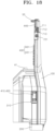
- the control unit 800 may turn on the line lamps 441 positioned in a lower section of the line lighting unit 440 among the plurality of line lamps 441.
- the lower section of the line lighting unit 440 may be variously changed in design within a section range positioned below the kinetic lighting unit 430 among all the sections of the line lighting unit 440.
- the control unit 800 may turn on the line lamps 441 positioned in a central section of the line lighting unit 440 among the plurality of line lamps 441.
- the central section of the line lighting unit 440 may be a section between the upper section and the lower section of the line lighting unit 440.
- the control unit 800 may turn on all the plurality of line lamps 441.
- the line lighting unit 440 may serve as a daytime running light (DRL).
- control unit 800 may repeatedly turn on and off the plurality of line lamps 441 at preset time intervals.
- the line lighting unit 440 may serve as a turn signal light.
- the main cabin 30 is disposed above the platform 10 and has an internal space in which a passenger is seated.
- the main cabin 30 according to the present embodiment may be provided in the form of a box opened at a lower side thereof and having an empty interior.
- Various items and devices such as a seat, an operation panel, a table, and the like, which conform to the purpose of the occupant, may be installed in the main cabin 30.
- the main cabin 30 In a state in which the open lower side of the main cabin 30 is disposed to be directed toward the upper surface of the platform 10, the main cabin 30 may move downward toward the platform 10, such that the main cabin 30 may be seated on the platform 10.
- an upper end of the main cabin 30 may be positioned at a lower height than an upper end of the pillar body 100.
- an outer surface of the main cabin 30 may be disposed to be spaced apart from the inner surface of the pillar body 100 at a predetermined interval. Therefore, the main cabin 30 may ensure an operating space for the kinetic lighting unit 430.
- the main cabin 30 may move upward from the platform 10, such that the main cabin 30 may be separated from the platform 10. Therefore, the main cabin 30 may be freely replaced.
- the cross-sectional area and the shape of the main cabin 30 are not limited to the shapes illustrated in FIGS. 1 and 2 , but may be variously changed in design depending on the shape of the platform 10 or the like.
- the docking unit 40 is provided between the pillar module 20 and the main cabin 30 and fastens the pillar module 20 and the main cabin 30 while operating in conjunction with the upward movement of the main cabin 30.
- FIG. 22 is an enlarged view schematically illustrating a configuration of the docking unit according to the present embodiment.
- the first docking member 41 is provided on the pillar body 100 and defines an external appearance of one side of the docking unit 40.
- the first docking member 41 according to the present embodiment may formed to have a cylindrical shape extending from one side of the pillar body 100.
- the first docking member 41 may be disposed so that a longitudinal direction thereof is parallel to a direction in which the main cabin 30 is seated on the platform 10. That is, as illustrated in FIG. 22 , the first docking member 41 may be disposed so that the longitudinal direction thereof is perpendicular to the ground surface.
- the arrangement position of the first docking member 41 is not limited to that illustrated in FIG.
- the first docking member 41 may be provided as a plurality of first docking members 41.
- the plurality of first docking members 41 may be independently installed for each of the pillar bodies 100 provided on the pillar modules 20.
- the second docking member 42 is provided on the main cabin 30 and defines an external appearance of the other side of the docking unit 40. As the main cabin 30 is seated on the platform 10, the first docking member 41 may be inserted into the second docking member 42 and fasten the pillar module 20 and the main cabin 30.
- the second docking member 42 according to the present embodiment may be provided in the form of a groove concavely recessed upward from a lower surface of the main cabin 30.
- the second docking member 42 may be disposed so that a longitudinal direction thereof is parallel to the direction in which the main cabin 30 is seated on the platform 10. That is, as illustrated in FIG. 22 , the second docking member 42 may be disposed so that the longitudinal direction thereof is perpendicular to the ground surface.
- the second docking member 42 may be disposed at a position at which a central axis of the second docking member 42 is positioned coaxially with a central axis of the first docking member 41.
- the second docking member 42 may be provided as a plurality of second docking members 42.
- the plurality of second docking members 42 may correspond in number to the first docking members 41.
- first docking member 41 is inserted into the second docking member 42.
- first docking member 41 and the second docking member 42 are not limited thereto, and the second docking member 42 may be inserted into the first docking member 41.
- the first docking member 41 may be provided in the form of a groove concavely recessed toward the inside of the pillar body 100
- the second docking member 42 may be provided in the form of a protrusion protruding from the main cabin 30.
- the stopper 50 is installed on the pillar body 100 and prevents the main cabin 30 from separating from the platform 10. That is, after the main cabin 30 is seated on the platform 10 and the first docking member 41 and the second docking member 42 are fastened to each other, the stopper 50 serves to restrict an upward movement of the main cabin 30 toward an upper side of the platform 10.
- the stopper 50 may be provided as a plurality of stoppers 50. The plurality of stoppers 50 may be independently installed for each of the pillar bodies 100 provided on the pillar modules 20.
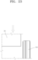
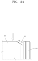
- FIGS. 23 and 24 are views schematically illustrating a configuration and an operating state of the stopper according to the first embodiment of the present disclosure.
- the stopper 50 may be provided in the form of a rod extending from the upper end of the pillar body 100 toward the main cabin 30.
- the stopper 50 may be detachably coupled to the pillar body 100. Therefore, the stopper 50 may not interfere with the main cabin 30 during the process in which the main cabin 30 is seated on the platform 10.
- the stopper 50 may be disposed to intersect the direction in which the first docking member 41 and the second docking member 42 are inserted, i.e., the direction in which the main cabin 30 is seated on the platform 10. For example, as illustrated in FIG.
- the stopper 50 may be disposed to be inclined at a predetermined angle toward the main cabin 30 with respect to the direction perpendicular to the ground surface. As the main cabin 30 is completely seated on the platform 10, the stopper 50 may be coupled to the pillar body 100, and a lower surface of the stopper 50 comes into contact with the upper surface of the main cabin 30, which makes it possible to prevent the separation of the main cabin 30.
- the door unit 60 opens or closes the internal space of the main cabin 30 so that the passenger may get in the main cabin 30.
- FIG. 25 is a block diagram schematically illustrating a configuration of the door unit according to the first embodiment of the present disclosure.
- the door unit 60 includes a door 61 and a door control unit 62.
- the door 61 is movably connected to the main cabin 30 and opens or closes the internal space of the main cabin 30 depending on a movement direction.
- Examples of the door 61 according to the present embodiment may include various types of opening/closing means that may open or close the internal space of the main cabin 30 in a hinged or sliding manner.
- the door 61 may be provided as a plurality of doors 61.
- the plurality of doors 61 may be disposed to be spaced apart from one another along the peripheral surface of the main cabin 30.
- FIG. 2 illustrates an example in which two doors 61 are provided, but the number of doors 61 and the arrangement state of the door 61 are not limited thereto.
- the number of doors 61 and the arrangement state of the door 61 may be variously changed in design.
- the door control unit 62 individually controls the operation of opening or closing the plurality of doors 61 on the basis of data detected from the detection unit 700.
- the door control unit 62 may include at least any one of an electronic control unit (ECU), a central processing unit (CPU), a processor, and a system on chip (SoC).
- the door control unit 62 may control a plurality of hardware or software constituent elements by operating an operating system or an application and perform various types of data processing and computation.
- the door control unit 62 may be configured to execute at least one instruction stored in a memory and store data, related to the result of executing the instruction, in the memory.
- FIG. 26 is a view schematically illustrating an operating state of the door unit according to the first embodiment of the present disclosure.
- the detection unit 700 detects a position of the driver, the passenger, or the like.
- the door control unit 62 calculates a distance from the door 61 and the detection unit 700 to the detected driver or passenger on the basis of information on the position of the driver or passenger detected by the detection unit 700 and previously inputted information on the positions of the plurality of doors 61.
- the vehicle having the pillar module according to the second embodiment of the present disclosure differs from the vehicle having the pillar module according to the first embodiment of the present disclosure only in that the vehicle having the pillar module according to the second embodiment of the present disclosure further includes a transport cabin 31. Therefore, in the description of the configuration of the vehicle having the pillar module according to the second embodiment of the present disclosure, only the transport cabin 31, which is the difference between the vehicle having the pillar module according to the second embodiment of the present disclosure and the vehicle having the pillar module according to the first embodiment of the present disclosure, will be described.
- the corresponding description of the vehicle having the pillar module according to the first embodiment of the present disclosure applies without change to the description of the remaining components of the vehicle having the pillar module according to the second embodiment of the present disclosure.
- the vehicle having the pillar module according to the present embodiment may further include the transport cabin 31.
- the transport cabin 31 is stacked on the main cabin 30 and detachably coupled to the main cabin 30.
- the transport cabin 31 serves to expand a luggage loading space of the vehicle separately from the main cabin 30.
- the transport cabin 31 may be provided in the form of a box opened at a lower side thereof and having an empty interior.
- a cross-sectional area of the transport cabin 31 may be smaller than a cross-sectional area of the main cabin 30. Therefore, in case that the transport cabin 31 is stacked on the main cabin 30, the interference with the stopper 50 may be prevented.
- the transport cabin 31 may be detachably coupled to the main cabin 30 by bolting, docking, or the like.
Landscapes
- Engineering & Computer Science (AREA)
- Mechanical Engineering (AREA)
- Chemical & Material Sciences (AREA)
- Combustion & Propulsion (AREA)
- Transportation (AREA)
- Physics & Mathematics (AREA)
- Acoustics & Sound (AREA)
- Manufacturing & Machinery (AREA)
- Lighting Device Outwards From Vehicle And Optical Signal (AREA)
- Arrangement Of Elements, Cooling, Sealing, Or The Like Of Lighting Devices (AREA)
Abstract
Description
- Exemplary embodiments of the present disclosure relate to a pillar module, and more particularly, to a pillar module in which a power device, a lighting device, and a sensing device of a vehicle are integrated into a single device.
- In general, an electric vehicle refers to a vehicle that may use electrical energy, which is stored in a battery, as a power source. The advantage of the electric vehicle is that neither soot nor smoke is produced, little noise is generated, and a vehicle body is lightweight.
- Furthermore, new mobility visions with new concepts for implementing human-oriented dynamic future cities have been introduced to vehicle industries. One of the future mobility solutions is a purpose-built vehicle (PBV) as a purpose-based mobility vehicle.
- However, in the case of a vehicle in the related art, a drive device, a lighting device, a sensing device, and the like are separated as separate structures and systems, which makes it difficult to apply the drive device, the lighting device, the sensing device, and the like to the PBV used for various purposes.
- The background technology of the present disclosure is disclosed in
Korean Patent No. 10-2336410 (registered on December 2, 2021 - This Summary is provided to introduce a selection of concepts in a simplified form that are further described below in the Detailed Description. This Summary is not intended to identify key features or essential features of the claimed subject matter, nor is it intended to be used as an aid in determining the scope of the claimed subject matter.
- An object of the present disclosure is to provide a pillar module in which a power device, a lighting device, and a sensing device of a vehicle are integrated into a single device.
- An object of the present disclosure is to provide a pillar module capable of being applied to various mobility vehicles on the basis of a high degree of design freedom.
- In an embodiment, a pillar module may include: a pillar body; a drive unit connected to the pillar body and configured to support the pillar body so that the pillar body is movable; a first lighting unit installed on the pillar body and configured to create a first lighting pattern; a second lighting unit disposed to be spaced apart from the first lighting unit and configured to create a second lighting pattern; and a switching unit connected to the first lighting unit and the second lighting unit and configured to selectively expose the first lighting unit and the second lighting unit to the outside of the pillar body.
- An accommodation portion having an opening side formed at one side thereof may be formed in the pillar body, and the first lighting unit and the second lighting unit may be disposed in the accommodation portion and selectively face the opening side while operating in conjunction with an operation of the switching unit.
- The switching unit may include: a switching case rotatably installed in the accommodation portion and configured to support the first lighting unit and the second lighting unit; and a switching actuator connected to the switching case and configured to generate a rotational force to rotate the switching case.
- A central axis of the switching case may be disposed in parallel with the opening side.
- The first lighting unit and the second lighting unit may be disposed to be spaced apart from each other along a peripheral surface of the switching case.
- The first lighting unit may include a road surface illumination lamp configured to rotate together with the switching case and configured to emit an optical image toward a road surface as the road surface illumination lamp is disposed to face the opening side.
- The second lighting unit may include a plurality of pixel lamps configured to rotate together with the switching case and be independently turned on or off.
- The plurality of pixel lamps may be arranged in the form of a lattice on a peripheral surface of the switching case.
- The pillar module may further include: a kinetic lighting unit movably installed on the pillar body and configured to create a kinetic lighting pattern.
- The kinetic lighting unit may include a plurality of kinetic lighting members independently movably installed on the pillar body and disposed to be spaced apart from one another.
- The kinetic lighting member may include: a kinetic panel including an one side rotatably connected to the pillar body, and an other side protruding outward from the pillar body or inserted into the pillar body depending on a rotation direction; a kinetic actuator connected to the one side of the kinetic panel and configured to generate a rotational force to rotate the kinetic panel; and a kinetic lamp configured to be exposed to outside of the pillar body as the other side of the kinetic panel protrudes outward from the pillar body.
- The pillar module may further include: a line lighting unit extending in an upward/downward direction along an outer surface of the pillar module.
- The line lighting unit may include a plurality of line lamps disposed to be spaced apart from one another in an extension direction of the line lighting unit and configured to be independently turned on or off.
- The pillar module may further include: a detection unit installed on the pillar body and configured to detect an object positioned at a periphery of the pillar body; and a control unit configured to control operations of the first lighting unit, the second lighting unit, and the switching unit.
- The detection unit may include a first detection member rotatably installed on the pillar body and configured to rotate in conjunction with a change in relative position between the pillar body and the object.
- According to the pillar module according to the present disclosure, the power device configured to move the vehicle, the lighting device configured to transmit an optical signal, and the sensing device configured to perform an interaction with a pedestrian at the periphery of the vehicle may be integrated into a single unit module, which makes it possible to fluidly apply the pillar module to mobility vehicles having various specifications and purposes.
- In addition, according to the pillar module according to the present disclosure, the first lighting unit and the second lighting unit may be configured to selectively face the opening side in the accommodation portion by the switching unit, which makes it possible to improve spatial utilization and an overall aesthetic appearance of the vehicle in comparison with the case in which the first lighting unit and the second lighting unit are installed at different positions on the pillar body.
- In addition, according to the pillar module according to the present disclosure, various types of lighting patterns may be created by the first lighting unit, the second lighting unit, the kinetic lighting unit, and the line lighting unit, which makes it possible to ensure safety for an object positioned outside the vehicle and more effectively transfer various types of information on the states of the vehicle.
-
-
FIG. 1 is a perspective view schematically illustrating a configuration of a vehicle having a pillar module according to a first embodiment of the present disclosure. -
FIG. 2 is an exploded perspective view schematically illustrating a configuration of the vehicle having the pillar module according to the first embodiment of the present disclosure. -
FIG. 3 is a perspective view schematically illustrating a configuration of the pillar module according to the first embodiment of the present disclosure. -
FIG. 4 is a perspective view illustrating a configuration of the pillar module according to the first embodiment of the present disclosure when viewed at a point in time different from a point in time inFIG. 3 . -
FIG. 5 is a block diagram schematically illustrating a configuration of the pillar module according to the first embodiment of the present disclosure. -
FIG. 6 is a cross-sectional view schematically illustrating a configuration of a switching unit according to the first embodiment of the present disclosure. -
FIG. 7 is a perspective view schematically illustrating a configuration of a first lighting unit according to the first embodiment of the present disclosure. -
FIG. 8 is a perspective view schematically illustrating a configuration of a second lighting unit according to the first embodiment of the present disclosure. -
FIG. 9 is a perspective view schematically illustrating a configuration of a kinetic lighting unit according to the first embodiment of the present disclosure. -
FIG. 10 is a front view schematically illustrating a configuration of the kinetic lighting unit according to the first embodiment of the present disclosure. -
FIGS. 11 and12 are side views schematically illustrating a configuration of the kinetic lighting unit according to the first embodiment of the present disclosure. -
FIG. 13 is an enlarged view schematically illustrating an operating state of a flap according to the first embodiment of the present disclosure. -
FIG. 14 is an enlarged view schematically illustrating a configuration of a detection unit according to the first embodiment of the present disclosure. -
FIG. 15 is a view schematically illustrating an operation of creating a first lighting pattern by the first lighting unit according to the first embodiment of the present disclosure. -
FIG. 16 is a view schematically illustrating an operation of creating a second lighting pattern by the second lighting unit according to the first embodiment of the present disclosure. -
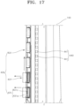
FIG. 17 is a view schematically illustrating an operation of creating a kinetic lighting pattern by the kinetic lighting unit according to the first embodiment of the present disclosure. -
FIGS. 18 to 21 are views schematically illustrating an operation of creating a line lighting pattern by a line lighting unit according to the first embodiment of the present disclosure. -
FIG. 22 is an enlarged view schematically illustrating a configuration of a docking unit according to the present embodiment. -
FIGS. 23 and24 are views schematically illustrating a configuration and an operating state of a stopper according to the first embodiment of the present disclosure. -
FIG. 25 is a block diagram schematically illustrating a configuration of a door unit according to the first embodiment of the present disclosure. -
FIG. 26 is a view schematically illustrating an operating state of the door unit according to the first embodiment of the present disclosure. -
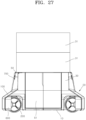
FIG. 27 is a front view schematically illustrating a configuration of a vehicle having a pillar module according to a second embodiment of the present disclosure. - The following detailed description is provided to assist the reader in gaining a comprehensive understanding of the methods, apparatuses, and/or systems described herein. However, various changes, modifications, and equivalents of the methods, apparatuses, and/or systems described herein will be apparent after an understanding of the disclosure of this application. For example, the sequences of operations described herein are merely examples, and are not limited to those set forth herein, but may be changed as will be apparent after an understanding of the disclosure of this application, with the exception of operations necessarily occurring in a certain order.
- The features described herein may be embodied in different forms and are not to be construed as being limited to the examples described herein. Rather, the examples described herein have been provided merely to illustrate some of the many possible ways of implementing the methods, apparatuses, and/or systems described herein that will be apparent after an understanding of the disclosure of this application.
- Advantages and features of the present disclosure and methods of achieving the advantages and features will be clear with reference to embodiments described in detail below together with the accompanying drawings. However, the present disclosure is not limited to the embodiments disclosed herein but will be implemented in various forms. The embodiments of the present disclosure are provided so that the present disclosure is completely disclosed, and a person with ordinary skill in the art can fully understand the scope of the present disclosure. The present disclosure will be defined only by the scope of the appended claims. Meanwhile, the terms used in the present specification are for explaining the embodiments, not for limiting the present disclosure.
- Terms, such as first, second, A, B, (a), (b) or the like, may be used herein to describe components. Each of these terminologies is not used to define an essence, order or sequence of a corresponding component but used merely to distinguish the corresponding component from other component(s). For example, a first component may be referred to as a second component, and similarly the second component may also be referred to as the first component.
- Throughout the specification, when a component is described as being "connected to," or "coupled to" another component, it may be directly "connected to," or "coupled to" the other component, or there may be one or more other components intervening therebetween. In contrast, when an element is described as being "directly connected to," or "directly coupled to" another element, there can be no other elements intervening therebetween.
- The singular forms "a", "an", and "the" are intended to include the plural forms as well, unless the context clearly indicates otherwise. It will be further understood that the terms "comprises/comprising" and/or "includes/including" when used herein, specify the presence of stated features, integers, steps, operations, elements, and/or components, but do not preclude the presence or addition of one or more other features, integers, steps, operations, elements, components and/or groups thereof.
- Hereinafter, a vehicle having a pillar module will be described below with reference to the accompanying drawings through various exemplary embodiments.
-
FIG. 1 is a perspective view schematically illustrating a configuration of a vehicle having a pillar module according to a first embodiment of the present disclosure, andFIG. 2 is an exploded perspective view schematically illustrating a configuration of the vehicle having the pillar module according to the first embodiment of the present disclosure. - Referring to
FIGS. 1 and2 , a vehicle according to the present embodiment may include aplatform 10, apillar module 20, amain cabin 30, adocking unit 40, astopper 50, and adoor unit 60. - The
platform 10 defines a lower external appearance of the vehicle according to the present embodiment and entirely supports thepillar module 20 and themain cabin 30 which will be described below. Theplatform 10 according to the present embodiment may be formed to have a flat plate shape. Theplatform 10 may be disposed to be parallel to the ground surface. Theplatform 10 may be supported to be spaced apart from the ground surface by means of thepillar module 20 to be described below. A battery (not illustrated) may be installed on theplatform 10 and supply power to thepillar module 20, thedoor unit 60, and various types of electronic devices installed in the vehicle. The battery may be seated on an upper surface of theplatform 10. Alternatively, the battery may be coupled to a lower surface of theplatform 10. A cross-sectional shape of theplatform 10 is not limited to a quadrangular shape illustrated inFIG. 2 , but may be changed in design to various shapes such as a circular shape, an elliptical shape, or a polygonal shape. - The
pillar module 20 is connected to theplatform 10 and supports theplatform 10. Thepillar module 20 is configured such that a power device configured to move the vehicle, a lighting device configured to transmit an optical signal, and a sensing device configured to perform an interaction with a pedestrian at the periphery of the vehicle are integrated into a single unit module and simultaneously or independently perform these functions. Therefore, thepillar module 20 may be fluidly applied to theplatform 10 and themain cabin 30 that have various specifications and purposes. Thepillar module 20 may be provided as a plurality ofpillar modules 20. The plurality ofpillar modules 20 may be disposed to be spaced apart from one another along a periphery of theplatform 10. For example, the plurality ofpillar modules 20 may be provided as fourpillar modules 20 respectively disposed at edge portions of theplatform 10 having a quadrangular cross-section. However, the number ofpillar modules 20 and the arrangement state of thepillar modules 20 are not limited thereto, but may be variously changed in design depending on the cross-sectional shape or the like of theplatform 10. -
FIG. 3 is a perspective view schematically illustrating a configuration of the pillar module according to the first embodiment of the present disclosure,FIG. 4 is a perspective view illustrating a configuration of the pillar module according to the first embodiment of the present disclosure when viewed at a point in time different from a point in time inFIG. 3 , andFIG. 5 is a block diagram schematically illustrating a configuration of the pillar module according to the first embodiment of the present disclosure. - Referring to
FIGS. 3 to 5 , thepillar module 20 according to the present embodiment includes apillar body 100, adrive unit 200, aswitching unit 300, afirst lighting unit 410, asecond lighting unit 420, akinetic lighting unit 430, aline lighting unit 440, aspeaker unit 500, aflap 600, adetection unit 700, and acontrol unit 800. - The
pillar body 100 defines a schematic external appearance of thepillar module 20 and entirely supports thedrive unit 200, theswitching unit 300, thefirst lighting unit 410, thesecond lighting unit 420, thekinetic lighting unit 430, theline lighting unit 440, thespeaker unit 500, theflap 600, and thedetection unit 700 which will be described below. Thepillar body 100 according to the present embodiment may be provided in the form of a box or wheel housing opened at an outer side thereof and having an empty interior at a lower side thereof. Therefore, thepillar body 100 may provide a space at the lower side thereof so that thedrive unit 200 to be described below may be installed in the space. An upper side of thepillar body 100 may be provided in the form of a column extending in an upward/downward direction. However, the shape of thepillar body 100 is not limited to the shape illustrated inFIGS. 3 and4 . Thepillar body 100 may be variously changed in design within the technical spirit of the shape in order to entirely support thedrive unit 200, theswitching unit 300, thefirst lighting unit 410, thesecond lighting unit 420, thekinetic lighting unit 430, theline lighting unit 440, thespeaker unit 500, theflap 600, and thedetection unit 700. - The
pillar body 100 may have anaccommodation portion 110 for accommodating theswitching unit 300, thefirst lighting unit 410, and thesecond lighting unit 420 which will be described below. Theaccommodation portion 110 according to the present embodiment may be provided in the form of a groove concavely extending toward the inside of thepillar body 100 from a front surface of thepillar body 100 disposed to be directed toward a front or rear side of the vehicle. Theaccommodation portion 110 may be disposed at a lower side of thepillar body 100. An opening side 111a may be formed in one surface of theaccommodation portion 110 and connect an internal space of theaccommodation portion 110 and an external space of theaccommodation portion 110. The opening side 111a may be disposed on the same plane as the front surface of thepillar body 100. The cross-sectional shape and cross-sectional area of theaccommodation portion 110 are not limited to the shapes or areas illustrated inFIGS. 3 and4 . Theaccommodation portion 110 may be variously changed in design depending on the specifications of theswitching unit 300, thefirst lighting unit 410, and thesecond lighting unit 420 which will be described below. - The
drive unit 200 is connected to thepillar body 100 and supports thepillar body 100 so that thepillar body 100 is movable. More specifically, thedrive unit 200 is connected to thepillar body 100 and configured to perform overall functions such as a driving function, a braking function, a suspension function, and a steering function of the vehicle. Examples of thedrive unit 200 according to the present embodiment may include various types of independent drive wheels each including a wheel rotatably installed in the internal space at the lower side of thepillar body 100, an in-wheel motor configured to provide a rotational force to the wheel, a suspension configured to support the wheel on thepillar body 100, and a steering actuator configured to adjust a steering angle of the wheel by generating a rotational force. An operation of thedrive unit 200 may be adjusted by the control operation of thecontrol unit 800 or operations of a steering wheel, an accelerator, and a brake pedal made by a driver. - The
switching unit 300 is installed on thepillar body 100 and connected to thefirst lighting unit 410 and thesecond lighting unit 420 which will be described below. Theswitching unit 300 selectively exposes thefirst lighting unit 410 and thesecond lighting unit 420 to the outside of thepillar body 100. More specifically, theswitching unit 300 is installed in theaccommodation portion 110 and serves to adjust positions of thefirst lighting unit 410 and thesecond lighting unit 420 so that thefirst lighting unit 410 and thesecond lighting unit 420 selectively face theopening side 110a in theaccommodation portion 110 by driving power thereof. Therefore, theswitching unit 300 may improve spatial utilization and an overall aesthetic appearance of the product in comparison with a case in which thefirst lighting unit 410 and thesecond lighting unit 420, which create different lighting patterns, are installed at different positions on thepillar body 100. -
FIG. 6 is a cross-sectional view schematically illustrating a configuration of the switching unit according to the first embodiment of the present disclosure. - Referring to
FIG. 6 , theswitching unit 300 according to the present embodiment includes aswitching case 310 and a switchingactuator 320. - The switching
case 310 is rotatably installed in theaccommodation portion 110 and supports thefirst lighting unit 410 and thesecond lighting unit 420. The switchingcase 310 according to the present embodiment may be formed to have an approximately box shape and disposed in theaccommodation portion 110. The switchingcase 310 may be supported in theaccommodation portion 110 so as to be rotatable about a central axis thereof. In this case, the central axis of the switchingcase 310 may be disposed in parallel with theopening side 110a of theaccommodation portion 110. For example, the central axis of the switchingcase 310 may be disposed in parallel with a height direction of thepillar body 100, i.e., a direction perpendicular to the ground surface. The switchingcase 310 may be formed so that a cross-section perpendicular to the central axis has a polygonal shape. In this case, a peripheral surface of the switchingcase 310 may have a shape made by disposing a plurality of flat surfaces at predetermined angles around the central axis of the switchingcase 310. Therefore, in case that thefirst lighting unit 410 or thesecond lighting unit 420, which will be described below, is disposed to face theopening side 110a, the switchingcase 310 may guide light, which is emitted from thefirst lighting unit 410 or thesecond lighting unit 420, so that the light is emitted to the outside of thepillar body 100 through theopening side 110a. - The switching
actuator 320 is connected to theswitching case 310 and generates a rotational force to rotate theswitching case 310 about the central axis. Examples of the switchingactuator 320 according to the present embodiment may include various types of electric motors that generate the rotational force by receiving power from the outside. The switchingactuator 320 may be disposed in thepillar body 100. An output shaft of the switchingactuator 320 may be connected directly to theswitching case 310 and transmit the rotational force to theswitching case 310. Alternatively, the output shaft of the switchingactuator 320 may be connected to theswitching case 310 by means of a separate gear or the like and transmit the rotational force to theswitching case 310. The switchingactuator 320 may be electrically connected to thecontrol unit 800, and an operation of the switchingactuator 320 may be adjusted under the control of thecontrol unit 800. - The
first lighting unit 410 is installed on thepillar body 100 and creates a first lighting pattern. More specifically, thefirst lighting unit 410 may be disposed in theaccommodation portion 110 and connected to one side of the switchingcase 310. When the switchingcase 310 rotates, thefirst lighting unit 410 may rotate together with the switchingcase 310 in theaccommodation portion 110, such that a relative position of thefirst lighting unit 410 with respect to theopening side 110a may vary. In case that thefirst lighting unit 410 is disposed to face theopening side 110a, thefirst lighting unit 410 may be exposed to the outside of thepillar body 100 and display the first lighting pattern, which is created through theopening side 110a, to the outside of thepillar body 100. -
FIG. 7 is a perspective view schematically illustrating a configuration of the first lighting unit according to the first embodiment of the present disclosure. - Referring to
FIG. 7 , thefirst lighting unit 410 according to the present embodiment may include a roadsurface illumination lamp 411 and aheadlamp 412. In this case, the first lighting pattern, which is created by thefirst lighting unit 410, may mean a lighting pattern displayed to the outside of thepillar body 100 by the roadsurface illumination lamp 411, theheadlamp 412, or a combination thereof. - The road
surface illumination lamp 411 is connected to any one of peripheral surfaces of the switchingcase 310 and rotates together with the switchingcase 310. The roadsurface illumination lamp 411 is disposed to face theopening side 110a and emits an optical image toward the road surface. For example, the roadsurface illumination lamp 411 according to the present embodiment may be a projection device configured to project an optical image printed on a film or the like or a beam projector configured to project a recorded digital image. A central axis of a lens of the roadsurface illumination lamp 411, which emits an optical image, is disposed to be inclined downward at a predetermined angle with respect to a direction parallel to the ground surface. Therefore, the roadsurface illumination lamp 411 may guide the optical image emitted to the outside of thepillar body 100 so that the optical image is displayed on the road surface. Whether to turn on or off the roadsurface illumination lamp 411 may be adjusted under the control of thecontrol unit 800 to be described below. - The
headlamp 412 is disposed to be spaced apart from the roadsurface illumination lamp 411 and rotates together with the switchingcase 310. Theheadlamp 412 may be connected to the peripheral surface, which is identical to the peripheral surface to which the roadsurface illumination lamp 411 is connected among the peripheral surfaces of the switchingcase 310. For example, theheadlamp 412 may be disposed to be spaced apart from the roadsurface illumination lamp 411 in an upward/downward direction on the same peripheral surface of the switchingcase 310. As theheadlamp 412 is disposed to face theopening side 110a, theheadlamp 412 emits a beam pattern such as a low beam or a high beam to the outside of thepillar body 100. Examples of theheadlamp 412 according to the present embodiment may include various types of headlamp devices that include light sources, reflectors, lenses, and the like and illuminate a traveling route of the vehicle. Whether to turn on or off theheadlamp 412 may be adjusted under the control of thecontrol unit 800 to be described below. - The
second lighting unit 420 is disposed to be spaced apart from thefirst lighting unit 410 and creates a second lighting pattern. More specifically, thesecond lighting unit 420 may be disposed in theaccommodation portion 110 and connected to the other side of the switchingcase 310. When the switchingcase 310 rotates, thesecond lighting unit 420 may rotate together with the switchingcase 310 in theaccommodation portion 110, such that a relative position of thesecond lighting unit 420 with respect to theopening side 110a may vary. In case that thesecond lighting unit 420 is disposed to face theopening side 110a, thesecond lighting unit 420 may be exposed to the outside of thepillar body 100 and display the second lighting pattern, which is created through theopening side 110a, to the outside of thepillar body 100. In this case, in case that thefirst lighting unit 410 is disposed to face theopening side 110a, thesecond lighting unit 420 may be disposed to face an inner surface of theaccommodation portion 110. Therefore, thefirst lighting unit 410 and thesecond lighting unit 420 may be selectively exposed to the outside of thepillar body 100. -
FIG. 8 is a perspective view schematically illustrating a configuration of the second lighting unit according to the first embodiment of the present disclosure. - Referring to
FIG. 8 , thesecond lighting unit 420 according to the first embodiment of the present disclosure may include a plurality ofpixel lamps 421. In this case, the second lighting pattern created by thesecond lighting unit 420 may mean a lighting pattern displayed to the outside of thepillar body 100 by the plurality ofpixel lamps 421. - The plurality of
pixel lamps 421 may rotate together with the switchingcase 310 and be independently turned on or off. The plurality ofpixel lamps 421 may be connected to a peripheral surface which is different from the peripheral surface to which thefirst lighting unit 410 is connected among the peripheral surfaces of the switchingcase 310. The plurality ofpixel lamps 421 may be arranged in the form of a lattice on the peripheral surface of the switchingcase 310. For example, the plurality ofpixel lamps 421 may be arranged in two or more rows in the horizontal and vertical directions on the peripheral surface of the switchingcase 310. For example, each of thepixel lamps 421 according to the present embodiment may be an light-emitting diode (LED) lamp that may emit light by receiving power from the outside. The turned-on state of each of the plurality ofpixel lamps 421 may be independently adjusted under the control of thecontrol unit 800 to be described below. - The
kinetic lighting unit 430 is movably installed on thepillar body 100 and creates a kinetic lighting pattern. More specifically, thekinetic lighting unit 430 serves to create a lighting pattern made by a combination of a lighting signal, which is made by light, and a dynamic signal that is made by a physical motion for interacting with an object such as a pedestrian positioned outside thepillar body 100. Thekinetic lighting unit 430 may be disposed above thefirst lighting unit 410 and thesecond lighting unit 420. Therefore, thekinetic lighting unit 430 may be disposed at a position adjacent to a height of the eyes of the pedestrian positioned outside thepillar body 100, thereby further improving visibility of the lighting pattern. -
FIG. 9 is a perspective view schematically illustrating a configuration of the kinetic lighting unit according to the first embodiment of the present disclosure,FIG. 10 is a front view schematically illustrating a configuration of the kinetic lighting unit according to the first embodiment of the present disclosure, andFIGS. 11 and12 are side views schematically illustrating a configuration of the kinetic lighting unit according to the first embodiment of the present disclosure. - Referring to
FIGS. 9 to 12 , thekinetic lighting unit 430 according to the first embodiment of the present disclosure may include a plurality ofkinetic lighting members 431. In this case, the kinetic lighting pattern created by thekinetic lighting unit 430 may mean a lighting pattern displayed to the outside of thepillar body 100 by operations of the plurality ofkinetic lighting members 431. - The plurality of
kinetic lighting members 431 may be disposed at a central portion of thepillar body 100, more specifically disposed between theaccommodation portion 110 and thedetection unit 700 to be described below. The plurality ofkinetic lighting members 431 may be installed on thepillar body 100 so as to be independently moved and turned on or off. The plurality ofkinetic lighting members 431 may be disposed to be spaced apart from one another at predetermined intervals in the upward/downward direction in the height direction of thepillar body 100. The plurality ofkinetic lighting members 431 may create various types of kinetic lighting patterns while being independently moved and turned on or off under the control of thecontrol unit 800 to be described below. - The
kinetic lighting member 431 according to the present embodiment includes akinetic panel 431a, akinetic actuator 431b, and akinetic lamp 431c. - The
kinetic panel 431a may be formed to have a rod shape having an empty interior and opened at one side thereof. Thekinetic panel 431a may be disposed so that the open side thereof is directed toward thepillar body 100. The open side of thekinetic panel 431a may be inserted into thepillar body 100. In this case, thekinetic panel 431a may be inserted into an inner surface of thepillar body 100 disposed to face themain cabin 30, which will be described below, between two opposite lateral surfaces of thepillar body 100. Alternatively, thekinetic panel 431a may be inserted into an outer surface of thepillar body 100 disposed to be directed toward the outside of the vehicle. The closed side of thekinetic panel 431a may be disposed on the same plane as the outer surface of thepillar body 100. That is, the closed side of thekinetic panel 431a may be disposed to define a continuous plane together with the outer surface of thepillar body 100. - The
kinetic panel 431a may be disposed so that a longitudinal direction thereof is parallel to a forward/rearward direction of thepillar body 100, i.e., an extension direction of theaccommodation portion 110. One side of thekinetic panel 431a may be disposed to be directed toward a rear surface of thepillar body 100, i.e., a side opposite to the side at which theopening side 110a is defined. The other side of thekinetic panel 431a may be disposed to be directed toward the front surface of thepillar body 100, i.e., the same side at which theopening side 110a is defined. - One side of the
kinetic panel 431a may be rotatably connected to thepillar body 100. In this case, one side of thekinetic panel 431a may be supported to be rotatable about the height direction of thepillar body 100, i.e., the direction perpendicular to the ground surface. The other side of thekinetic panel 431a may protrude outward from thepillar body 100 or be inserted into thepillar body 100 depending on the rotation direction. In case that the other side of thekinetic panel 431a protrudes outward from thepillar body 100, an empty space may be defined between thekinetic panel 431a and thepillar body 100. - The
kinetic actuator 431b is connected to one side of thekinetic panel 431a and generates a rotational force to rotate thekinetic panel 431a. Examples of thekinetic actuator 431b according to the present embodiment may include various types of electric motors that generate the rotational force by receiving power from the outside. Thekinetic actuator 431b may be disposed in thepillar body 100. An output shaft of thekinetic actuator 431b may be connected directly to one side of thekinetic panel 431a and transmit the rotational force to thekinetic panel 431a. Alternatively, the output shaft of thekinetic actuator 431b may be connected to one side of thekinetic panel 431a by means of a separate gear and transmit the rotational force to thekinetic panel 431a. Thekinetic actuator 431b may be electrically connected to thecontrol unit 800 to be described below, and an operation of thekinetic actuator 431b may be adjusted under the control of thecontrol unit 800. - The
kinetic lamp 431c may be provided to be turned on or off. Thekinetic lamp 431c is exposed to the outside of thepillar body 100 as the other side of thekinetic panel 431a protrudes outward from thepillar body 100. Examples of thekinetic lamp 431c according to the present embodiment may include various types of LED lamps that may generate light by receiving power from the outside. Thekinetic lamp 431c may be disposed between the open side of thekinetic panel 431a and thepillar body 100. Thekinetic lamp 431c may be disposed at an end of the other side of thekinetic panel 431a. Therefore, thekinetic lamp 431c may be exposed to the outside of thepillar body 100 as the other side of thekinetic panel 431a protrudes outward from thepillar body 100 and the empty space is defined between thekinetic panel 431a and thepillar body 100. In this case, thekinetic lamp 431c may be connected integrally with the other side of thekinetic panel 431a and rotate together with the other side of thekinetic panel 431a. Alternatively, thekinetic lamp 431c may be separated from thekinetic panel 431a and fixed in position between thekinetic panel 431a and thepillar body 100. The turned-on state of thekinetic lamp 431c may be adjusted under the control of thecontrol unit 800. - The
line lighting unit 440 extends in the upward/downward direction along the outer surface of thepillar body 100 and creates a line lighting pattern. Theline lighting unit 440 may be disposed on the front surface of thepillar body 100, i.e., at a side identical to the side at which theopening side 110a is defined. - Referring to
FIGS. 9 and11 , theline lighting unit 440 according to the present embodiment may include a plurality ofline lamps 441. In this case, the line lighting pattern created by theline lighting unit 440 may mean a lighting pattern displayed to the outside of thepillar body 100 by operations of the plurality ofline lamps 441. - The plurality of
line lamps 441 may be disposed to be spaced apart from one another in the extension direction of theline lighting unit 440. The plurality ofline lamps 441 may be installed to be independently turned on or off. Therefore, only the plurality ofline lamps 441 in a partial section of the entire section of theline lighting unit 440 may be turned on, thereby implementing various types of lighting patterns. Examples of theline lamps 441 according to the present embodiment may include various types of LED lamps that may generate light by receiving power from the outside. The turned-on state of each of the plurality ofline lamps 441 may be independently adjusted under the control of thecontrol unit 800 to be described below. - The
speaker unit 500 is installed on thepillar body 100 and outputs sound to the outside of thepillar body 100. Thespeaker unit 500 according to the present embodiment may be a directional speaker that outputs sound at a predetermined angle in a particular direction or about the particular direction. Therefore, thespeaker unit 500 may output and guide sound so that the sound is concentrated on an object positioned outside thepillar body 100, thereby improving the recognition efficiency and preventing the occurrence of noise. Thespeaker unit 500 may be disposed in thepillar body 100. Thespeaker unit 500 may be disposed between theaccommodation portion 110 and thekinetic lighting unit 430. Thespeaker unit 500 may be disposed to be inclined at a predetermined angle toward the upper side of thepillar body 100. That is, thespeaker unit 500 may be disposed so that a direction in which sound is transmitted is inclined upward at a predetermined angle with respect to the direction parallel to the ground surface. - The
flap 600 is disposed to face thedrive unit 200 and prevents air from being introduced between thepillar body 100 and thedrive unit 200. Therefore, theflap 600 may prevent deterioration in traveling performance and fuel economy caused by air resistance. - Referring to
FIG. 3 , theflap 600 according to the present embodiment may be formed to have an approximately plate shape. An inner surface of theflap 600 may be disposed to face an outer surface of thedrive unit 200.FIG. 3 illustrates an example in which thesingle flap 600 is formed for any onepillar body 100. However, theflap 600 is not limited thereto, and a plurality offlaps 600 may be formed for any onepillar body 100. Theflap 600 may be movably connected to thepillar body 100 and move in conjunction with a steering operation of thedrive unit 200. Theflap 600 according to the present embodiment may be slidably connected to thepillar body 100 by means of a guide rail or the like. In this case, theflap 600 may be supported to be slidable in a direction parallel to a width direction of thepillar body 100. Theflap 600 may include a power device (not illustrated) such as an electric motor or a hydraulic cylinder and slide by receiving driving power from the power device. In this case, an operation of theflap 600 may be adjusted under the control of thecontrol unit 800 to be described below. Therefore, theflap 600 may guide a smooth steering operation of thedrive unit 200.FIG. 13 is an enlarged view schematically illustrating an operating state of the flap according to the first embodiment of the present disclosure. - Referring to
FIG. 13 , the wheel of thedrive unit 200 protrudes from a lateral surface of thepillar body 100 when the vehicle turns. - Because the wheel of the
drive unit 200 protrudes from the lateral surface of thepillar body 100, theflap 600 slides toward the outside of thepillar body 100 under the control of thecontrol unit 800 and is prevented from coming into contact with thedrive unit 200. - A movement amount of the
flap 600 may increase in proportion to a steering angle of the wheel of thedrive unit 200. - Thereafter, when a steering angle set to the wheel of the
drive unit 200 is eliminated so that the vehicle travels straight, theflap 600 may return to an initial position while sliding toward thepillar body 100 under the control of thecontrol unit 800. - The
detection unit 700 is installed on thepillar body 100 and detects an object at the periphery of thepillar body 100. In this case, examples of the object at the periphery of thepillar body 100 may include various types of objects such as pedestrians, the driver, obstacles that may be positioned at the periphery of thepillar body 100. Thedetection unit 700 may be disposed at the upper side of thepillar body 100, more specifically, above thekinetic lighting unit 430. Therefore, a detection range in which thedetection unit 700 detects an object may be expanded in comparison with the case in which thedetection unit 700 is disposed at a lower side of thepillar body 100. -
FIG. 14 is an enlarged view schematically illustrating a configuration of the detection unit according to the first embodiment of the present disclosure. - Referring to
FIG. 14 , thedetection unit 700 according to the present embodiment may include afirst detection member 710 and asecond detection member 720. - The
first detection member 710 is rotatably installed on thepillar body 100 and rotates in conjunction with a change in relative position between thepillar body 100 and an object. - The
first detection member 710 according to the present embodiment may include afirst detection body 711, avision sensor 712, and alidar sensor 713. - The
first detection body 711 may be disposed in thepillar body 100, and one surface of thefirst detection body 711 may be exposed to the outside of thepillar body 100. Thefirst detection body 711 may be connected to thepillar body 100 so as to be rotatable about an axis in height direction of thepillar body 100, i.e., the direction perpendicular to the ground surface. Thefirst detection body 711 is connected to thevision sensor 712 and thelidar sensor 713, which will be described below, and entirely supports thevision sensor 712 and thelidar sensor 713. In addition, thefirst detection body 711 may be connected to an electric motor (not illustrated) or the like that operates under the control of thecontrol unit 800, such that a rotation angle of thefirst detection body 711 may be adjusted. Thefirst detection body 711 may change the positions of thevision sensor 712 and thelidar sensor 713 while being rotated relative to thepillar body 100 by the operation of the electric motor. Therefore, thefirst detection body 711 may expand the detection ranges of thevision sensor 712 and thelidar sensor 713 each having a relatively small angle of view. - The
vision sensor 712 and thelidar sensor 713 may acquire three-dimensional images of the periphery of thepillar body 100 and detect position information, distance information, direction information, speed information, and the like of the object at the periphery of thepillar body 100 on the basis of the acquired images. Thevision sensor 712 may be implemented as a dynamic vision sensor (DVS). Thelidar sensor 713 may be implemented by a TOF (time of flight) manner or a phase-shift manner. Thevision sensor 712 and thelidar sensor 713 may be connected to one surface of thefirst detection body 711 and exposed to the outside of thepillar body 100. When thefirst detection body 711 rotates, thevision sensor 712 and thelidar sensor 713 rotate together with thefirst detection body 711 relative to thepillar body 100. Thevision sensor 712 and thelidar sensor 713 may be electrically connected to thecontrol unit 800 and transmit the detected data to thecontrol unit 800. - In addition, the
first detection member 710 may of course include any sensor that may acquire information on the object at the periphery of thepillar body 100 while rotating relative to thepillar body 100 even though the sensor is not described above. - The
second detection member 720 is fixed to thepillar body 100 and detects the object at the periphery of thepillar body 100. - The
second detection member 720 according to the present embodiment may include acamera 721 configured to capture a two-dimensional image of the periphery of thepillar body 100, and aradar sensor 722 configured to detect distance information of the object positioned at the periphery of thepillar body 100 by using an electromagnetic wave. - The
camera 721 may be disposed below thefirst detection member 710. Thecamera 721 may be electrically connected to thecontrol unit 800 and transfer information on the captured two-dimensional image of the periphery of thepillar body 100 to thecontrol unit 800. - The
radar sensor 722 may be disposed in thepillar body 100. Theradar sensor 722 may be electrically connected to thecontrol unit 800 and transmit the detected data to thecontrol unit 800. - In addition, the
second detection member 720 may of course include any sensor that may be fixed to thepillar body 100 and additionally acquire information on the object at the periphery of thepillar body 100 even though the sensor is not described above. - The
control unit 800 controls the overall operations of thedrive unit 200, theswitching unit 300, thefirst lighting unit 410, thesecond lighting unit 420, thekinetic lighting unit 430, theline lighting unit 440, thespeaker unit 500, theflap 600, and thedetection unit 700. More specifically, thecontrol unit 800 may control the operations of thedrive unit 200, theswitching unit 300, thefirst lighting unit 410, thesecond lighting unit 420, thekinetic lighting unit 430, theline lighting unit 440, thespeaker unit 500, theflap 600, and thedetection unit 700 on the basis of data detected by thedetection unit 700, data inputted in advance by the user, whether the vehicle is stationary, whether the vehicle is turned on or off, whether the battery is charged, whether the vehicle is steered, and the like. - The
control unit 800 may include at least any one of an electronic control unit (ECU), a central processing unit (CPU), a processor, and a system on chip (SoC). Thecontrol unit 800 may control a plurality of hardware or software constituent elements by operating an operating system or an application and perform various types of data processing and computation. Thecontrol unit 800 may be configured to execute at least one instruction stored in a memory and store data, related to the result of executing the instruction, in the memory. Thecontrol unit 800 may include at least any one of a radio frequency (RF) device, a wireless fidelity (Wi-Fi) device, a Bluetooth device, a Zigbee device, and a near field communication (NFC) device that may implement various types of communication protocols that may receive the data detected by thedetection unit 700 and the input signal generated from a terminal of the driver or various types of input devices. - Hereinafter, an operation of the
pillar module 20 according to the first embodiment of the present disclosure will be described in detail. -
FIG. 15 is a view schematically illustrating an operation of creating the first lighting pattern by the first lighting unit according to the first embodiment of the present disclosure. - Referring to
FIG. 15 , when thecontrol unit 800 determines that the vehicle is turned on, thecontrol unit 800 operates the switchingactuator 320 so that the switchingcase 310 rotates in the direction in which thefirst lighting unit 410 faces theopening side 110a. - When the
first lighting unit 410 is disposed to face theopening side 110a and exposed to the outside of thepillar body 100, thecontrol unit 800 operates the roadsurface illumination lamp 411. - More specifically, when the
control unit 800 determines that the vehicle is stationary or moves rearward, thecontrol unit 800 turns on the roadsurface illumination lamp 411. - The road
surface illumination lamp 411 emits an optical image on the road surface at the periphery of thepillar body 100. - Therefore, the road
surface illumination lamp 411 indicates a walking direction for a pedestrian by means of the optical image, which makes it possible to ensure safety for the pedestrian and enable the pedestrian to easily recognize the presence of the vehicle. - In addition, the
control unit 800 may turn on theheadlamp 412 on the basis of the user's input or data detected by a separate illuminance sensor (not illustrated), and theheadlamp 412 may emit a beam pattern to the outside of the vehicle. -
FIG. 16 is a view schematically illustrating an operation of creating the second lighting pattern by the second lighting unit according to the first embodiment of the present disclosure. - Referring to
FIG. 16 , when thecontrol unit 800 determines that the vehicle is turned off or the battery is being charged, thecontrol unit 800 operates the switchingactuator 320 so that the switchingcase 310 rotates in the direction in which thesecond lighting unit 420 faces theopening side 110a. - In case that the battery is being charged, the
control unit 800 may turn on the plurality ofpixel lamps 421 in proportion to a charge capacity of the battery. - For example, the
control unit 800 may calculate a ratio of the current charge amount of the battery to the maximum charge amount of the battery, turn on thepixel lamps 421 corresponding in number to the calculated ratio among all thepixel lamps 421, and turn off the remainingpixel lamps 421. - Thereafter, as the current charge amount of the battery increases, the
control unit 800 may sequentially turn on the turned-offpixel lamps 421 in the preset order. - In this case, the order in which the plurality of
pixel lamps 421 is turned on is not limited to the order illustrated inFIG. 16 , but may be changed in design to various orders. -
FIG. 17 is a view schematically illustrating an operation of creating the kinetic lighting pattern by the kinetic lighting unit according to the first embodiment of the present disclosure. - Referring to
FIG. 17 , thecontrol unit 800 may operate thekinetic lighting unit 430 when thecontrol unit 800 receives a separate input signal from the user, when the pedestrian is detected by thedetection unit 700, or when a preset condition related to charging of the battery or the like is satisfied. - In this case, the
control unit 800 may sequentially operate the plurality ofkinetic lighting members 431. - For example, the
control unit 800 may sequentially operate the plurality ofkinetic actuators 431b so that the other sides of thekinetic panels 431a protrude outward from thepillar body 100 in the order from thekinetic lighting member 431 positioned at the lower side to thekinetic lighting member 431 positioned at the upper side. - Thereafter, the
control unit 800 may sequentially operate the plurality ofkinetic actuators 431b so that the other sides of thekinetic panels 431a are inserted back into thepillar body 100 in the order from thekinetic lighting member 431 positioned at the lower side to thekinetic lighting member 431 positioned at the upper side. - At the same time, the
control unit 800 may maintain the turned-on state of the plurality ofkinetic lamps 431c. - However, the operations of the plurality of
kinetic panels 431a and the operations of thekinetic lamps 431c are not limited thereto, and the plurality ofkinetic panels 431a and thekinetic lamps 431c may be rotated and turned on in a preset order or randomly. -
FIGS. 18 to 21 are views schematically illustrating an operation of creating the line lighting pattern by the line lighting unit according to the first embodiment of the present disclosure. - Referring to
FIG. 18 , in case that thecontrol unit 800 determines that thedetection unit 700 is detecting an object positioned at the periphery of thepillar body 100, thecontrol unit 800 may turn on theline lamps 441 positioned in an upper section of theline lighting unit 440 among the plurality ofline lamps 441. In this case, for example, the upper section of theline lighting unit 440 may be a section positioned above thefirst detection member 710 among all the sections of theline lighting unit 440. - Therefore, the
line lighting unit 440 may display the situation, in which thedetection unit 700 currently recognizes the pedestrian or the like positioned outside thepillar body 100, to the outside of thepillar body 100, thereby providing psychological stability to the pedestrian or the like. - Referring to
FIG. 19 , in case that thecontrol unit 800 determines that thefirst lighting unit 410 or thesecond lighting unit 420 is operating, thecontrol unit 800 may turn on theline lamps 441 positioned in a lower section of theline lighting unit 440 among the plurality ofline lamps 441. In this case, the lower section of theline lighting unit 440 may be variously changed in design within a section range positioned below thekinetic lighting unit 430 among all the sections of theline lighting unit 440. - Referring to
FIG. 20 , in case that thecontrol unit 800 determines that thekinetic lighting unit 430 is operating, thecontrol unit 800 may turn on theline lamps 441 positioned in a central section of theline lighting unit 440 among the plurality ofline lamps 441. In this case, for example, the central section of theline lighting unit 440 may be a section between the upper section and the lower section of theline lighting unit 440. - Referring to
FIG. 21 , in case that thecontrol unit 800 determines that the vehicle is traveling, thecontrol unit 800 may turn on all the plurality ofline lamps 441. In this case, theline lighting unit 440 may serve as a daytime running light (DRL). - In addition, in case that the
control unit 800 determines that the vehicle is turning or is to turn, thecontrol unit 800 may repeatedly turn on and off the plurality ofline lamps 441 at preset time intervals. In this case, theline lighting unit 440 may serve as a turn signal light. - The
main cabin 30 is disposed above theplatform 10 and has an internal space in which a passenger is seated. Themain cabin 30 according to the present embodiment may be provided in the form of a box opened at a lower side thereof and having an empty interior. Various items and devices such as a seat, an operation panel, a table, and the like, which conform to the purpose of the occupant, may be installed in themain cabin 30. In a state in which the open lower side of themain cabin 30 is disposed to be directed toward the upper surface of theplatform 10, themain cabin 30 may move downward toward theplatform 10, such that themain cabin 30 may be seated on theplatform 10. In case that themain cabin 30 is seated on theplatform 10, an upper end of themain cabin 30 may be positioned at a lower height than an upper end of thepillar body 100. In case that themain cabin 30 is seated on theplatform 10, an outer surface of themain cabin 30 may be disposed to be spaced apart from the inner surface of thepillar body 100 at a predetermined interval. Therefore, themain cabin 30 may ensure an operating space for thekinetic lighting unit 430. In the state in which themain cabin 30 is seated on the upper surface of theplatform 10, themain cabin 30 may move upward from theplatform 10, such that themain cabin 30 may be separated from theplatform 10. Therefore, themain cabin 30 may be freely replaced. The cross-sectional area and the shape of themain cabin 30 are not limited to the shapes illustrated inFIGS. 1 and2 , but may be variously changed in design depending on the shape of theplatform 10 or the like. - The
docking unit 40 is provided between thepillar module 20 and themain cabin 30 and fastens thepillar module 20 and themain cabin 30 while operating in conjunction with the upward movement of themain cabin 30. -
FIG. 22 is an enlarged view schematically illustrating a configuration of the docking unit according to the present embodiment. - Referring to
FIGS. 1 ,2 , and22 , thedocking unit 40 according to the present embodiment includes afirst docking member 41 and asecond docking member 42. - The
first docking member 41 is provided on thepillar body 100 and defines an external appearance of one side of thedocking unit 40. Thefirst docking member 41 according to the present embodiment may formed to have a cylindrical shape extending from one side of thepillar body 100. Thefirst docking member 41 may be disposed so that a longitudinal direction thereof is parallel to a direction in which themain cabin 30 is seated on theplatform 10. That is, as illustrated inFIG. 22 , thefirst docking member 41 may be disposed so that the longitudinal direction thereof is perpendicular to the ground surface. The arrangement position of thefirst docking member 41 is not limited to that illustrated inFIG. 2 , but may be variously changed in design to a position at which thefirst docking member 41 may perpendicularly face themain cabin 30 in the upward/downward direction during the process in which themain cabin 30 is seated on theplatform 10. Thefirst docking member 41 may be provided as a plurality offirst docking members 41. The plurality offirst docking members 41 may be independently installed for each of thepillar bodies 100 provided on thepillar modules 20. - The
second docking member 42 is provided on themain cabin 30 and defines an external appearance of the other side of thedocking unit 40. As themain cabin 30 is seated on theplatform 10, thefirst docking member 41 may be inserted into thesecond docking member 42 and fasten thepillar module 20 and themain cabin 30. Thesecond docking member 42 according to the present embodiment may be provided in the form of a groove concavely recessed upward from a lower surface of themain cabin 30. Thesecond docking member 42 may be disposed so that a longitudinal direction thereof is parallel to the direction in which themain cabin 30 is seated on theplatform 10. That is, as illustrated inFIG. 22 , thesecond docking member 42 may be disposed so that the longitudinal direction thereof is perpendicular to the ground surface. In case that themain cabin 30 is seated on theplatform 10, thesecond docking member 42 may be disposed at a position at which a central axis of thesecond docking member 42 is positioned coaxially with a central axis of thefirst docking member 41. Thesecond docking member 42 may be provided as a plurality ofsecond docking members 42. The plurality ofsecond docking members 42 may correspond in number to thefirst docking members 41. - The example has been described above in which the
first docking member 41 is inserted into thesecond docking member 42. However, thefirst docking member 41 and thesecond docking member 42 are not limited thereto, and thesecond docking member 42 may be inserted into thefirst docking member 41. In this case, thefirst docking member 41 may be provided in the form of a groove concavely recessed toward the inside of thepillar body 100, and thesecond docking member 42 may be provided in the form of a protrusion protruding from themain cabin 30. - The
stopper 50 is installed on thepillar body 100 and prevents themain cabin 30 from separating from theplatform 10. That is, after themain cabin 30 is seated on theplatform 10 and thefirst docking member 41 and thesecond docking member 42 are fastened to each other, thestopper 50 serves to restrict an upward movement of themain cabin 30 toward an upper side of theplatform 10. Thestopper 50 may be provided as a plurality ofstoppers 50. The plurality ofstoppers 50 may be independently installed for each of thepillar bodies 100 provided on thepillar modules 20. -
FIGS. 23 and24 are views schematically illustrating a configuration and an operating state of the stopper according to the first embodiment of the present disclosure. - Referring to
FIGS. 23 and24 , thestopper 50 according to the present embodiment may be provided in the form of a rod extending from the upper end of thepillar body 100 toward themain cabin 30. Thestopper 50 may be detachably coupled to thepillar body 100. Therefore, thestopper 50 may not interfere with themain cabin 30 during the process in which themain cabin 30 is seated on theplatform 10. Thestopper 50 may be disposed to intersect the direction in which thefirst docking member 41 and thesecond docking member 42 are inserted, i.e., the direction in which themain cabin 30 is seated on theplatform 10. For example, as illustrated inFIG. 24 , thestopper 50 may be disposed to be inclined at a predetermined angle toward themain cabin 30 with respect to the direction perpendicular to the ground surface. As themain cabin 30 is completely seated on theplatform 10, thestopper 50 may be coupled to thepillar body 100, and a lower surface of thestopper 50 comes into contact with the upper surface of themain cabin 30, which makes it possible to prevent the separation of themain cabin 30. - The
door unit 60 opens or closes the internal space of themain cabin 30 so that the passenger may get in themain cabin 30. -
FIG. 25 is a block diagram schematically illustrating a configuration of the door unit according to the first embodiment of the present disclosure. - Referring to
FIGS. 2 and25 , thedoor unit 60 according to the present embodiment includes adoor 61 and adoor control unit 62. - The
door 61 is movably connected to themain cabin 30 and opens or closes the internal space of themain cabin 30 depending on a movement direction. Examples of thedoor 61 according to the present embodiment may include various types of opening/closing means that may open or close the internal space of themain cabin 30 in a hinged or sliding manner. Thedoor 61 may be provided as a plurality ofdoors 61. The plurality ofdoors 61 may be disposed to be spaced apart from one another along the peripheral surface of themain cabin 30.FIG. 2 illustrates an example in which twodoors 61 are provided, but the number ofdoors 61 and the arrangement state of thedoor 61 are not limited thereto. The number ofdoors 61 and the arrangement state of thedoor 61 may be variously changed in design. - The
door control unit 62 individually controls the operation of opening or closing the plurality ofdoors 61 on the basis of data detected from thedetection unit 700. Thedoor control unit 62 may include at least any one of an electronic control unit (ECU), a central processing unit (CPU), a processor, and a system on chip (SoC). Thedoor control unit 62 may control a plurality of hardware or software constituent elements by operating an operating system or an application and perform various types of data processing and computation. Thedoor control unit 62 may be configured to execute at least one instruction stored in a memory and store data, related to the result of executing the instruction, in the memory. Thedoor control unit 62 may include at least any one of a radio frequency (RF) device, a wireless fidelity (Wi-Fi) device, a Bluetooth device, a Zigbee device, and a near field communication (NFC) device that may implement various types of communication protocols that may receive the data detected by thedetection unit 700. -
FIG. 26 is a view schematically illustrating an operating state of the door unit according to the first embodiment of the present disclosure. - Referring to
FIG. 26 , as a driver, a passenger, or the like approaches the periphery of the vehicle, thedetection unit 700 detects a position of the driver, the passenger, or the like. - The
door control unit 62 calculates a distance from thedoor 61 and thedetection unit 700 to the detected driver or passenger on the basis of information on the position of the driver or passenger detected by thedetection unit 700 and previously inputted information on the positions of the plurality ofdoors 61. - The
door control unit 62 determines thedoor 61 positioned to be closest to the driver or passenger, among the plurality ofdoors 61, on the basis of the calculated distance information, and opens thecorresponding door 61. -
FIG. 27 is a front view schematically illustrating a configuration of a vehicle having a pillar module according to a second embodiment of the present disclosure. - The vehicle having the pillar module according to the second embodiment of the present disclosure differs from the vehicle having the pillar module according to the first embodiment of the present disclosure only in that the vehicle having the pillar module according to the second embodiment of the present disclosure further includes a
transport cabin 31. Therefore, in the description of the configuration of the vehicle having the pillar module according to the second embodiment of the present disclosure, only thetransport cabin 31, which is the difference between the vehicle having the pillar module according to the second embodiment of the present disclosure and the vehicle having the pillar module according to the first embodiment of the present disclosure, will be described. The corresponding description of the vehicle having the pillar module according to the first embodiment of the present disclosure applies without change to the description of the remaining components of the vehicle having the pillar module according to the second embodiment of the present disclosure. - Referring to
FIG. 27 , the vehicle having the pillar module according to the present embodiment may further include thetransport cabin 31. - The
transport cabin 31 is stacked on themain cabin 30 and detachably coupled to themain cabin 30. Thetransport cabin 31 serves to expand a luggage loading space of the vehicle separately from themain cabin 30. - The
transport cabin 31 according to the present embodiment may be provided in the form of a box opened at a lower side thereof and having an empty interior. A cross-sectional area of thetransport cabin 31 may be smaller than a cross-sectional area of themain cabin 30. Therefore, in case that thetransport cabin 31 is stacked on themain cabin 30, the interference with thestopper 50 may be prevented. Thetransport cabin 31 may be detachably coupled to themain cabin 30 by bolting, docking, or the like. - The
transport cabin 31 may be provided as a plurality oftransport cabins 31. The plurality oftransport cabins 31 may be sequentially stacked on themain cabin 30. In this case, thetransport cabin 31, which is disposed at a lowermost end among the plurality oftransport cabins 31, may be detachably coupled to themain cabin 30. Theadjacent transport cabins 31 may be detachably coupled to each other by bolting, docking, or the like. Therefore, the number of stackedtransport cabins 31 may be freely adjusted depending on a capacity for luggage to be loaded. - While the present disclosure has been described with reference to the embodiments depicted in the drawings, the embodiments are for illustrative purposes only, and those skilled in the art to which the present technology pertains will understand that various modifications of the embodiments and any other embodiments equivalent thereto are available.
Claims (15)
- A pillar module comprising:a pillar body;a drive unit connected to the pillar body and configured to support the pillar body so that the pillar body is movable;a first lighting unit installed on the pillar body and configured to create a first lighting pattern;a second lighting unit disposed to be spaced apart from the first lighting unit and configured to create a second lighting pattern; anda switching unit connected to the first lighting unit and the second lighting unit and configured to selectively expose the first lighting unit and the second lighting unit to the outside of the pillar body.
- The pillar module of claim 1, wherein an accommodation portion having an opening side formed at one side thereof is formed in the pillar body, and
wherein the first lighting unit and the second lighting unit are disposed in the accommodation portion and selectively face the opening side while operating in conjunction with an operation of the switching unit. - The pillar module of claim 2, wherein the switching unit comprises:a switching case rotatably installed in the accommodation portion and configured to support the first lighting unit and the second lighting unit; anda switching actuator connected to the switching case and configured to generate a rotational force to rotate the switching case.
- The pillar module of claim 3, wherein a central axis of the switching case is disposed in parallel with the opening side.
- The pillar module of claim 3 or 4, wherein the first lighting unit and the second lighting unit are disposed to be spaced apart from each other along a peripheral surface of the switching case.
- The pillar module of any one of claims 3 to 5, wherein the first lighting unit comprises a road surface illumination lamp configured to rotate together with the switching case and configured to emit an optical image toward a road surface as the road surface illumination lamp is disposed to face the opening side.
- The pillar module of any one of claim 3 to 6, wherein the second lighting unit comprises a plurality of pixel lamps configured to rotate together with the switching case and be independently turned on or off.
- The pillar module of claim 7, wherein the plurality of pixel lamps is arranged in the form of a lattice on a peripheral surface of the switching case.
- The pillar module of any one of claims 1 to 8, further comprising:
a kinetic lighting unit movably installed on the pillar body and configured to create a kinetic lighting pattern. - The pillar module of claim 9, wherein the kinetic lighting unit comprises a plurality of kinetic lighting members independently movably installed on the pillar body and disposed to be spaced apart from one another.
- The pillar module of claim 10, wherein the kinetic lighting member comprises:a kinetic panel including an one side rotatably connected to the pillar body, and an other side protruding outward from the pillar body or inserted into the pillar body depending on a rotation direction;a kinetic actuator connected to the one side of the kinetic panel and configured to generate a rotational force to rotate the kinetic panel; anda kinetic lamp configured to be exposed to outside of the pillar body as the other side of the kinetic panel protrudes outward from the pillar body.
- The pillar module of any one of claims 1 to 11, further comprising:
a line lighting unit extending in an upward/downward direction along an outer surface of the pillar module. - The pillar module of claim 12, wherein the line lighting unit comprises a plurality of line lamps disposed to be spaced apart from one another in an extension direction of the line lighting unit and configured to be independently turned on or off.
- The pillar module of any one of claims 1 to 13, further comprising:a detection unit installed on the pillar body and configured to detect an object positioned at a periphery of the pillar body; anda control unit configured to control operations of the first lighting unit, the second lighting unit, and the switching unit.
- The pillar module of claim 14, wherein the detection unit comprises a first detection member rotatably installed on the pillar body and configured to rotate in conjunction with a change in relative position between the pillar body and the object.
Applications Claiming Priority (1)
| Application Number | Priority Date | Filing Date | Title |
|---|---|---|---|
| KR1020220188768A KR102748861B1 (en) | 2022-12-29 | 2022-12-29 | Pillar module |
Publications (2)
| Publication Number | Publication Date |
|---|---|
| EP4393797A1 true EP4393797A1 (en) | 2024-07-03 |
| EP4393797B1 EP4393797B1 (en) | 2025-08-27 |
Family
ID=85640890
Family Applications (1)
| Application Number | Title | Priority Date | Filing Date |
|---|---|---|---|
| EP23161649.1A Active EP4393797B1 (en) | 2022-12-29 | 2023-03-14 | Pillar module |
Country Status (4)
| Country | Link |
|---|---|
| US (1) | US12030428B1 (en) |
| EP (1) | EP4393797B1 (en) |
| KR (1) | KR102748861B1 (en) |
| CN (1) | CN118269804A (en) |
Families Citing this family (1)
| Publication number | Priority date | Publication date | Assignee | Title |
|---|---|---|---|---|
| KR20230076047A (en) * | 2021-11-23 | 2023-05-31 | 현대모비스 주식회사 | Corner module apparatus for vehicle and vehicle having the same |
Citations (7)
| Publication number | Priority date | Publication date | Assignee | Title |
|---|---|---|---|---|
| US20180345777A1 (en) * | 2017-05-31 | 2018-12-06 | Zoox, Inc. | Vehicle with interchangeable drive modules |
| US11180207B2 (en) * | 2020-01-02 | 2021-11-23 | Ree Automotive Ltd. | Vehicle corner modules and vehicles comprising them |
| KR102336410B1 (en) | 2020-04-22 | 2021-12-08 | 현대자동차주식회사 | Prefabricated vehicle |
| DE102020131008A1 (en) * | 2020-06-17 | 2021-12-23 | Hyundai Motor Company | VEHICLE CORNER MODULE |
| US20220126918A1 (en) * | 2019-12-31 | 2022-04-28 | Ree Automotive Ltd | Vehicle chassis platform |
| US11479295B1 (en) * | 2021-07-28 | 2022-10-25 | Ree Automotive Ltd. | Vehicle corner module and methods for installation thereof |
| WO2022254382A1 (en) * | 2021-06-04 | 2022-12-08 | Ree Automotive Ltd. | Vehicle corner modules and systems and methods for installation thereof |
Family Cites Families (5)
| Publication number | Priority date | Publication date | Assignee | Title |
|---|---|---|---|---|
| DE102004004471A1 (en) * | 2003-02-01 | 2004-08-05 | Marquardt Gmbh | Electric switch, especially for motor vehicle, e.g. for light operating unit, has actuating element that can be moved out of housing by pulling force in opposite direction to insertion force |
| KR20060067545A (en) * | 2004-12-15 | 2006-06-20 | 현대모비스 주식회사 | User selectable rear lamp |
| JP6305456B2 (en) * | 2016-03-31 | 2018-04-04 | 株式会社Subaru | Display device |
| US10807523B2 (en) * | 2016-07-29 | 2020-10-20 | Ts Tech Co., Ltd. | Light emitting unit for conveyance |
| KR102329632B1 (en) * | 2020-02-17 | 2021-11-22 | 현대모비스 주식회사 | Apparatus of lighting for vehicle |
-
2022
- 2022-12-29 KR KR1020220188768A patent/KR102748861B1/en active Active
-
2023
- 2023-03-14 EP EP23161649.1A patent/EP4393797B1/en active Active
- 2023-04-07 CN CN202310366453.5A patent/CN118269804A/en active Pending
- 2023-06-15 US US18/335,293 patent/US12030428B1/en active Active
Patent Citations (7)
| Publication number | Priority date | Publication date | Assignee | Title |
|---|---|---|---|---|
| US20180345777A1 (en) * | 2017-05-31 | 2018-12-06 | Zoox, Inc. | Vehicle with interchangeable drive modules |
| US20220126918A1 (en) * | 2019-12-31 | 2022-04-28 | Ree Automotive Ltd | Vehicle chassis platform |
| US11180207B2 (en) * | 2020-01-02 | 2021-11-23 | Ree Automotive Ltd. | Vehicle corner modules and vehicles comprising them |
| KR102336410B1 (en) | 2020-04-22 | 2021-12-08 | 현대자동차주식회사 | Prefabricated vehicle |
| DE102020131008A1 (en) * | 2020-06-17 | 2021-12-23 | Hyundai Motor Company | VEHICLE CORNER MODULE |
| WO2022254382A1 (en) * | 2021-06-04 | 2022-12-08 | Ree Automotive Ltd. | Vehicle corner modules and systems and methods for installation thereof |
| US11479295B1 (en) * | 2021-07-28 | 2022-10-25 | Ree Automotive Ltd. | Vehicle corner module and methods for installation thereof |
Also Published As
| Publication number | Publication date |
|---|---|
| US20240217429A1 (en) | 2024-07-04 |
| KR102748861B1 (en) | 2025-01-03 |
| EP4393797B1 (en) | 2025-08-27 |
| CN118269804A (en) | 2024-07-02 |
| US12030428B1 (en) | 2024-07-09 |
| KR20240106126A (en) | 2024-07-08 |
Similar Documents
| Publication | Publication Date | Title |
|---|---|---|
| US10906532B2 (en) | Autonomous vehicle and method for controlling the same | |
| CN108688552B (en) | Vehicle control device provided in vehicle and vehicle control method thereof | |
| EP3290271B1 (en) | Lamp and autonomous vehicle | |
| EP3476697B1 (en) | Device for automatically parking vehicle and method for controlling the same | |
| US10611293B2 (en) | Lamp for vehicle | |
| EP3190005B1 (en) | Lamp for vehicle, and vehicle including the same | |
| EP3093193B1 (en) | Lamp for vehicle | |
| EP3421328B1 (en) | Parking assistance system | |
| CN108613098B (en) | Vehicle lamp and control method thereof | |
| US11180135B2 (en) | Autonomous parking system and vehicle | |
| US10047925B2 (en) | Headlamp for vehicle | |
| US20190077419A1 (en) | Autonomous driving control apparatus, driving information output apparatus, autonomous driving control method, and driving information output method | |
| CN107696954B (en) | Vehicle control device and vehicle control method provided in vehicle | |
| EP3281833A1 (en) | Regenerative braking control apparatus for vehicles | |
| EP3466755B1 (en) | Lamp for vehicle | |
| KR20210054271A (en) | APPARATUS AND METHOD FOR MANAGING POWER OF MULTI SoC MODULE IN VEHICLE | |
| CN108253375A (en) | Vehicle lamp and its control method | |
| US20170050641A1 (en) | Vehicle Assistance Apparatus And Vehicle | |
| CN108237964A (en) | Vehicle lamp and its control method | |
| EP4393797B1 (en) | Pillar module | |
| CN112776705B (en) | System and method for controlling a patterned skin lighting device of a vehicle | |
| KR20240106127A (en) | Vehicle having pillar module | |
| US12128833B2 (en) | Light assembly for motor vehicle | |
| KR102765843B1 (en) | Sensor module mounted on vehicle lamp | |
| KR20210100345A (en) | Electronic device of vehicle for obtaining an image by controlling a plurality of light sources and operating method thereof |
Legal Events
| Date | Code | Title | Description |
|---|---|---|---|
| PUAI | Public reference made under article 153(3) epc to a published international application that has entered the european phase |
Free format text: ORIGINAL CODE: 0009012 |
|
| STAA | Information on the status of an ep patent application or granted ep patent |
Free format text: STATUS: THE APPLICATION HAS BEEN PUBLISHED |
|
| AK | Designated contracting states |
Kind code of ref document: A1 Designated state(s): AL AT BE BG CH CY CZ DE DK EE ES FI FR GB GR HR HU IE IS IT LI LT LU LV MC ME MK MT NL NO PL PT RO RS SE SI SK SM TR |
|
| STAA | Information on the status of an ep patent application or granted ep patent |
Free format text: STATUS: REQUEST FOR EXAMINATION WAS MADE |
|
| 17P | Request for examination filed |
Effective date: 20241231 |
|
| GRAP | Despatch of communication of intention to grant a patent |
Free format text: ORIGINAL CODE: EPIDOSNIGR1 |
|
| STAA | Information on the status of an ep patent application or granted ep patent |
Free format text: STATUS: GRANT OF PATENT IS INTENDED |
|
| INTG | Intention to grant announced |
Effective date: 20250324 |
|
| GRAS | Grant fee paid |
Free format text: ORIGINAL CODE: EPIDOSNIGR3 |
|
| GRAA | (expected) grant |
Free format text: ORIGINAL CODE: 0009210 |
|
| STAA | Information on the status of an ep patent application or granted ep patent |
Free format text: STATUS: THE PATENT HAS BEEN GRANTED |
|
| AK | Designated contracting states |
Kind code of ref document: B1 Designated state(s): AL AT BE BG CH CY CZ DE DK EE ES FI FR GB GR HR HU IE IS IT LI LT LU LV MC ME MK MT NL NO PL PT RO RS SE SI SK SM TR |
|
| P01 | Opt-out of the competence of the unified patent court (upc) registered |
Free format text: CASE NUMBER: UPC_APP_0479_4393797/2025 Effective date: 20250717 |
|
| REG | Reference to a national code |
Ref country code: CH Ref legal event code: EP |
|
| REG | Reference to a national code |
Ref country code: DE Ref legal event code: R096 Ref document number: 602023005982 Country of ref document: DE |
|
| REG | Reference to a national code |
Ref country code: IE Ref legal event code: FG4D |
|
| REG | Reference to a national code |
Ref country code: NL Ref legal event code: MP Effective date: 20250827 |
|
| PG25 | Lapsed in a contracting state [announced via postgrant information from national office to epo] |
Ref country code: IS Free format text: LAPSE BECAUSE OF FAILURE TO SUBMIT A TRANSLATION OF THE DESCRIPTION OR TO PAY THE FEE WITHIN THE PRESCRIBED TIME-LIMIT Effective date: 20251227 |
|
| PG25 | Lapsed in a contracting state [announced via postgrant information from national office to epo] |
Ref country code: NO Free format text: LAPSE BECAUSE OF FAILURE TO SUBMIT A TRANSLATION OF THE DESCRIPTION OR TO PAY THE FEE WITHIN THE PRESCRIBED TIME-LIMIT Effective date: 20251127 |
|
| REG | Reference to a national code |
Ref country code: LT Ref legal event code: MG9D |
|
| PG25 | Lapsed in a contracting state [announced via postgrant information from national office to epo] |
Ref country code: PT Free format text: LAPSE BECAUSE OF FAILURE TO SUBMIT A TRANSLATION OF THE DESCRIPTION OR TO PAY THE FEE WITHIN THE PRESCRIBED TIME-LIMIT Effective date: 20251229 |
|
| PG25 | Lapsed in a contracting state [announced via postgrant information from national office to epo] |
Ref country code: FI Free format text: LAPSE BECAUSE OF FAILURE TO SUBMIT A TRANSLATION OF THE DESCRIPTION OR TO PAY THE FEE WITHIN THE PRESCRIBED TIME-LIMIT Effective date: 20250827 |
|
| PG25 | Lapsed in a contracting state [announced via postgrant information from national office to epo] |
Ref country code: HR Free format text: LAPSE BECAUSE OF FAILURE TO SUBMIT A TRANSLATION OF THE DESCRIPTION OR TO PAY THE FEE WITHIN THE PRESCRIBED TIME-LIMIT Effective date: 20250827 Ref country code: NL Free format text: LAPSE BECAUSE OF FAILURE TO SUBMIT A TRANSLATION OF THE DESCRIPTION OR TO PAY THE FEE WITHIN THE PRESCRIBED TIME-LIMIT Effective date: 20250827 |
|
| PG25 | Lapsed in a contracting state [announced via postgrant information from national office to epo] |
Ref country code: GR Free format text: LAPSE BECAUSE OF FAILURE TO SUBMIT A TRANSLATION OF THE DESCRIPTION OR TO PAY THE FEE WITHIN THE PRESCRIBED TIME-LIMIT Effective date: 20251128 |
|
| PG25 | Lapsed in a contracting state [announced via postgrant information from national office to epo] |
Ref country code: SE Free format text: LAPSE BECAUSE OF FAILURE TO SUBMIT A TRANSLATION OF THE DESCRIPTION OR TO PAY THE FEE WITHIN THE PRESCRIBED TIME-LIMIT Effective date: 20250827 |
|
| PG25 | Lapsed in a contracting state [announced via postgrant information from national office to epo] |
Ref country code: LV Free format text: LAPSE BECAUSE OF FAILURE TO SUBMIT A TRANSLATION OF THE DESCRIPTION OR TO PAY THE FEE WITHIN THE PRESCRIBED TIME-LIMIT Effective date: 20250827 |
|
| PG25 | Lapsed in a contracting state [announced via postgrant information from national office to epo] |
Ref country code: PL Free format text: LAPSE BECAUSE OF FAILURE TO SUBMIT A TRANSLATION OF THE DESCRIPTION OR TO PAY THE FEE WITHIN THE PRESCRIBED TIME-LIMIT Effective date: 20250827 Ref country code: BG Free format text: LAPSE BECAUSE OF FAILURE TO SUBMIT A TRANSLATION OF THE DESCRIPTION OR TO PAY THE FEE WITHIN THE PRESCRIBED TIME-LIMIT Effective date: 20250827 |
|
| PG25 | Lapsed in a contracting state [announced via postgrant information from national office to epo] |
Ref country code: RS Free format text: LAPSE BECAUSE OF FAILURE TO SUBMIT A TRANSLATION OF THE DESCRIPTION OR TO PAY THE FEE WITHIN THE PRESCRIBED TIME-LIMIT Effective date: 20251127 |
|
| PG25 | Lapsed in a contracting state [announced via postgrant information from national office to epo] |
Ref country code: ES Free format text: LAPSE BECAUSE OF FAILURE TO SUBMIT A TRANSLATION OF THE DESCRIPTION OR TO PAY THE FEE WITHIN THE PRESCRIBED TIME-LIMIT Effective date: 20250827 |
|
| REG | Reference to a national code |
Ref country code: AT Ref legal event code: MK05 Ref document number: 1829709 Country of ref document: AT Kind code of ref document: T Effective date: 20250827 |
|
| PG25 | Lapsed in a contracting state [announced via postgrant information from national office to epo] |
Ref country code: SM Free format text: LAPSE BECAUSE OF FAILURE TO SUBMIT A TRANSLATION OF THE DESCRIPTION OR TO PAY THE FEE WITHIN THE PRESCRIBED TIME-LIMIT Effective date: 20250827 |
|
| PG25 | Lapsed in a contracting state [announced via postgrant information from national office to epo] |
Ref country code: DK Free format text: LAPSE BECAUSE OF FAILURE TO SUBMIT A TRANSLATION OF THE DESCRIPTION OR TO PAY THE FEE WITHIN THE PRESCRIBED TIME-LIMIT Effective date: 20250827 |
|
| PGFP | Annual fee paid to national office [announced via postgrant information from national office to epo] |
Ref country code: DE Payment date: 20260120 Year of fee payment: 4 |
|
| PG25 | Lapsed in a contracting state [announced via postgrant information from national office to epo] |
Ref country code: AT Free format text: LAPSE BECAUSE OF FAILURE TO SUBMIT A TRANSLATION OF THE DESCRIPTION OR TO PAY THE FEE WITHIN THE PRESCRIBED TIME-LIMIT Effective date: 20250827 |
|
| PG25 | Lapsed in a contracting state [announced via postgrant information from national office to epo] |
Ref country code: IT Free format text: LAPSE BECAUSE OF FAILURE TO SUBMIT A TRANSLATION OF THE DESCRIPTION OR TO PAY THE FEE WITHIN THE PRESCRIBED TIME-LIMIT Effective date: 20250827 |
|
| PGFP | Annual fee paid to national office [announced via postgrant information from national office to epo] |
Ref country code: FR Payment date: 20260121 Year of fee payment: 4 |
|
| PG25 | Lapsed in a contracting state [announced via postgrant information from national office to epo] |
Ref country code: CZ Free format text: LAPSE BECAUSE OF FAILURE TO SUBMIT A TRANSLATION OF THE DESCRIPTION OR TO PAY THE FEE WITHIN THE PRESCRIBED TIME-LIMIT Effective date: 20250827 |
|
| PG25 | Lapsed in a contracting state [announced via postgrant information from national office to epo] |
Ref country code: EE Free format text: LAPSE BECAUSE OF FAILURE TO SUBMIT A TRANSLATION OF THE DESCRIPTION OR TO PAY THE FEE WITHIN THE PRESCRIBED TIME-LIMIT Effective date: 20250827 Ref country code: SK Free format text: LAPSE BECAUSE OF FAILURE TO SUBMIT A TRANSLATION OF THE DESCRIPTION OR TO PAY THE FEE WITHIN THE PRESCRIBED TIME-LIMIT Effective date: 20250827 |
|
| REG | Reference to a national code |
Ref country code: DE Ref legal event code: R097 Ref document number: 602023005982 Country of ref document: DE |
|
| PG25 | Lapsed in a contracting state [announced via postgrant information from national office to epo] |
Ref country code: LT Free format text: LAPSE BECAUSE OF FAILURE TO SUBMIT A TRANSLATION OF THE DESCRIPTION OR TO PAY THE FEE WITHIN THE PRESCRIBED TIME-LIMIT Effective date: 20250827 |
|
| PLBE | No opposition filed within time limit |
Free format text: ORIGINAL CODE: 0009261 |
|
| STAA | Information on the status of an ep patent application or granted ep patent |
Free format text: STATUS: NO OPPOSITION FILED WITHIN TIME LIMIT |
|
| REG | Reference to a national code |
Ref country code: CH Ref legal event code: L10 Free format text: ST27 STATUS EVENT CODE: U-0-0-L10-L00 (AS PROVIDED BY THE NATIONAL OFFICE) Effective date: 20260708 |
|
| 26N | No opposition filed |
Effective date: 20260528 |