EP4393791A1 - Pull drift compensation assist system and control method - Google Patents
Pull drift compensation assist system and control method Download PDFInfo
- Publication number
- EP4393791A1 EP4393791A1 EP21961027.6A EP21961027A EP4393791A1 EP 4393791 A1 EP4393791 A1 EP 4393791A1 EP 21961027 A EP21961027 A EP 21961027A EP 4393791 A1 EP4393791 A1 EP 4393791A1
- Authority
- EP
- European Patent Office
- Prior art keywords
- compensation
- drift compensation
- differential drive
- vehicle
- drive assist
- Prior art date
- Legal status (The legal status is an assumption and is not a legal conclusion. Google has not performed a legal analysis and makes no representation as to the accuracy of the status listed.)
- Granted
Links
Images



Classifications
-
- B—PERFORMING OPERATIONS; TRANSPORTING
- B62—LAND VEHICLES FOR TRAVELLING OTHERWISE THAN ON RAILS
- B62D—MOTOR VEHICLES; TRAILERS
- B62D6/00—Arrangements for automatically controlling steering depending on driving conditions sensed and responded to, e.g. control circuits
- B62D6/04—Arrangements for automatically controlling steering depending on driving conditions sensed and responded to, e.g. control circuits responsive only to forces disturbing the intended course of the vehicle, e.g. forces acting transversely to the direction of vehicle travel
-
- B—PERFORMING OPERATIONS; TRANSPORTING
- B60—VEHICLES IN GENERAL
- B60L—PROPULSION OF ELECTRICALLY-PROPELLED VEHICLES; SUPPLYING ELECTRIC POWER FOR AUXILIARY EQUIPMENT OF ELECTRICALLY-PROPELLED VEHICLES; ELECTRODYNAMIC BRAKE SYSTEMS FOR VEHICLES IN GENERAL; MAGNETIC SUSPENSION OR LEVITATION FOR VEHICLES; MONITORING OPERATING VARIABLES OF ELECTRICALLY-PROPELLED VEHICLES; ELECTRIC SAFETY DEVICES FOR ELECTRICALLY-PROPELLED VEHICLES
- B60L1/00—Supplying electric power to auxiliary equipment of vehicles
- B60L1/003—Supplying electric power to auxiliary equipment of vehicles to auxiliary motors, e.g. for pumps, compressors
-
- B—PERFORMING OPERATIONS; TRANSPORTING
- B60—VEHICLES IN GENERAL
- B60L—PROPULSION OF ELECTRICALLY-PROPELLED VEHICLES; SUPPLYING ELECTRIC POWER FOR AUXILIARY EQUIPMENT OF ELECTRICALLY-PROPELLED VEHICLES; ELECTRODYNAMIC BRAKE SYSTEMS FOR VEHICLES IN GENERAL; MAGNETIC SUSPENSION OR LEVITATION FOR VEHICLES; MONITORING OPERATING VARIABLES OF ELECTRICALLY-PROPELLED VEHICLES; ELECTRIC SAFETY DEVICES FOR ELECTRICALLY-PROPELLED VEHICLES
- B60L15/00—Methods, circuits, or devices for controlling the traction-motor speed of electrically-propelled vehicles
- B60L15/20—Methods, circuits, or devices for controlling the traction-motor speed of electrically-propelled vehicles for control of the vehicle or its driving motor to achieve a desired performance, e.g. speed, torque, programmed variation of speed
- B60L15/2036—Electric differentials, e.g. for supporting steering vehicles
-
- B—PERFORMING OPERATIONS; TRANSPORTING
- B60—VEHICLES IN GENERAL
- B60W—CONJOINT CONTROL OF VEHICLE SUB-UNITS OF DIFFERENT TYPE OR DIFFERENT FUNCTION; CONTROL SYSTEMS SPECIALLY ADAPTED FOR HYBRID VEHICLES; ROAD VEHICLE DRIVE CONTROL SYSTEMS FOR PURPOSES NOT RELATED TO THE CONTROL OF A PARTICULAR SUB-UNIT
- B60W10/00—Conjoint control of vehicle sub-units of different type or different function
- B60W10/04—Conjoint control of vehicle sub-units of different type or different function including control of propulsion units
- B60W10/08—Conjoint control of vehicle sub-units of different type or different function including control of propulsion units including control of electric propulsion units, e.g. motors or generators
-
- B—PERFORMING OPERATIONS; TRANSPORTING
- B60—VEHICLES IN GENERAL
- B60L—PROPULSION OF ELECTRICALLY-PROPELLED VEHICLES; SUPPLYING ELECTRIC POWER FOR AUXILIARY EQUIPMENT OF ELECTRICALLY-PROPELLED VEHICLES; ELECTRODYNAMIC BRAKE SYSTEMS FOR VEHICLES IN GENERAL; MAGNETIC SUSPENSION OR LEVITATION FOR VEHICLES; MONITORING OPERATING VARIABLES OF ELECTRICALLY-PROPELLED VEHICLES; ELECTRIC SAFETY DEVICES FOR ELECTRICALLY-PROPELLED VEHICLES
- B60L2220/00—Electrical machine types; Structures or applications thereof
- B60L2220/40—Electrical machine applications
- B60L2220/42—Electrical machine applications with use of more than one motor
-
- B—PERFORMING OPERATIONS; TRANSPORTING
- B60—VEHICLES IN GENERAL
- B60L—PROPULSION OF ELECTRICALLY-PROPELLED VEHICLES; SUPPLYING ELECTRIC POWER FOR AUXILIARY EQUIPMENT OF ELECTRICALLY-PROPELLED VEHICLES; ELECTRODYNAMIC BRAKE SYSTEMS FOR VEHICLES IN GENERAL; MAGNETIC SUSPENSION OR LEVITATION FOR VEHICLES; MONITORING OPERATING VARIABLES OF ELECTRICALLY-PROPELLED VEHICLES; ELECTRIC SAFETY DEVICES FOR ELECTRICALLY-PROPELLED VEHICLES
- B60L2220/00—Electrical machine types; Structures or applications thereof
- B60L2220/40—Electrical machine applications
- B60L2220/46—Wheel motors, i.e. motor connected to only one wheel
-
- B—PERFORMING OPERATIONS; TRANSPORTING
- B60—VEHICLES IN GENERAL
- B60L—PROPULSION OF ELECTRICALLY-PROPELLED VEHICLES; SUPPLYING ELECTRIC POWER FOR AUXILIARY EQUIPMENT OF ELECTRICALLY-PROPELLED VEHICLES; ELECTRODYNAMIC BRAKE SYSTEMS FOR VEHICLES IN GENERAL; MAGNETIC SUSPENSION OR LEVITATION FOR VEHICLES; MONITORING OPERATING VARIABLES OF ELECTRICALLY-PROPELLED VEHICLES; ELECTRIC SAFETY DEVICES FOR ELECTRICALLY-PROPELLED VEHICLES
- B60L2240/00—Control parameters of input or output; Target parameters
- B60L2240/10—Vehicle control parameters
- B60L2240/12—Speed
-
- B—PERFORMING OPERATIONS; TRANSPORTING
- B60—VEHICLES IN GENERAL
- B60L—PROPULSION OF ELECTRICALLY-PROPELLED VEHICLES; SUPPLYING ELECTRIC POWER FOR AUXILIARY EQUIPMENT OF ELECTRICALLY-PROPELLED VEHICLES; ELECTRODYNAMIC BRAKE SYSTEMS FOR VEHICLES IN GENERAL; MAGNETIC SUSPENSION OR LEVITATION FOR VEHICLES; MONITORING OPERATING VARIABLES OF ELECTRICALLY-PROPELLED VEHICLES; ELECTRIC SAFETY DEVICES FOR ELECTRICALLY-PROPELLED VEHICLES
- B60L2240/00—Control parameters of input or output; Target parameters
- B60L2240/10—Vehicle control parameters
- B60L2240/14—Acceleration
- B60L2240/16—Acceleration longitudinal
-
- B—PERFORMING OPERATIONS; TRANSPORTING
- B60—VEHICLES IN GENERAL
- B60L—PROPULSION OF ELECTRICALLY-PROPELLED VEHICLES; SUPPLYING ELECTRIC POWER FOR AUXILIARY EQUIPMENT OF ELECTRICALLY-PROPELLED VEHICLES; ELECTRODYNAMIC BRAKE SYSTEMS FOR VEHICLES IN GENERAL; MAGNETIC SUSPENSION OR LEVITATION FOR VEHICLES; MONITORING OPERATING VARIABLES OF ELECTRICALLY-PROPELLED VEHICLES; ELECTRIC SAFETY DEVICES FOR ELECTRICALLY-PROPELLED VEHICLES
- B60L2240/00—Control parameters of input or output; Target parameters
- B60L2240/10—Vehicle control parameters
- B60L2240/14—Acceleration
- B60L2240/18—Acceleration lateral
-
- B—PERFORMING OPERATIONS; TRANSPORTING
- B60—VEHICLES IN GENERAL
- B60L—PROPULSION OF ELECTRICALLY-PROPELLED VEHICLES; SUPPLYING ELECTRIC POWER FOR AUXILIARY EQUIPMENT OF ELECTRICALLY-PROPELLED VEHICLES; ELECTRODYNAMIC BRAKE SYSTEMS FOR VEHICLES IN GENERAL; MAGNETIC SUSPENSION OR LEVITATION FOR VEHICLES; MONITORING OPERATING VARIABLES OF ELECTRICALLY-PROPELLED VEHICLES; ELECTRIC SAFETY DEVICES FOR ELECTRICALLY-PROPELLED VEHICLES
- B60L2240/00—Control parameters of input or output; Target parameters
- B60L2240/10—Vehicle control parameters
- B60L2240/14—Acceleration
- B60L2240/20—Acceleration angular
-
- B—PERFORMING OPERATIONS; TRANSPORTING
- B60—VEHICLES IN GENERAL
- B60L—PROPULSION OF ELECTRICALLY-PROPELLED VEHICLES; SUPPLYING ELECTRIC POWER FOR AUXILIARY EQUIPMENT OF ELECTRICALLY-PROPELLED VEHICLES; ELECTRODYNAMIC BRAKE SYSTEMS FOR VEHICLES IN GENERAL; MAGNETIC SUSPENSION OR LEVITATION FOR VEHICLES; MONITORING OPERATING VARIABLES OF ELECTRICALLY-PROPELLED VEHICLES; ELECTRIC SAFETY DEVICES FOR ELECTRICALLY-PROPELLED VEHICLES
- B60L2240/00—Control parameters of input or output; Target parameters
- B60L2240/10—Vehicle control parameters
- B60L2240/22—Yaw angle
-
- B—PERFORMING OPERATIONS; TRANSPORTING
- B60—VEHICLES IN GENERAL
- B60L—PROPULSION OF ELECTRICALLY-PROPELLED VEHICLES; SUPPLYING ELECTRIC POWER FOR AUXILIARY EQUIPMENT OF ELECTRICALLY-PROPELLED VEHICLES; ELECTRODYNAMIC BRAKE SYSTEMS FOR VEHICLES IN GENERAL; MAGNETIC SUSPENSION OR LEVITATION FOR VEHICLES; MONITORING OPERATING VARIABLES OF ELECTRICALLY-PROPELLED VEHICLES; ELECTRIC SAFETY DEVICES FOR ELECTRICALLY-PROPELLED VEHICLES
- B60L2240/00—Control parameters of input or output; Target parameters
- B60L2240/10—Vehicle control parameters
- B60L2240/24—Steering angle
-
- B—PERFORMING OPERATIONS; TRANSPORTING
- B60—VEHICLES IN GENERAL
- B60L—PROPULSION OF ELECTRICALLY-PROPELLED VEHICLES; SUPPLYING ELECTRIC POWER FOR AUXILIARY EQUIPMENT OF ELECTRICALLY-PROPELLED VEHICLES; ELECTRODYNAMIC BRAKE SYSTEMS FOR VEHICLES IN GENERAL; MAGNETIC SUSPENSION OR LEVITATION FOR VEHICLES; MONITORING OPERATING VARIABLES OF ELECTRICALLY-PROPELLED VEHICLES; ELECTRIC SAFETY DEVICES FOR ELECTRICALLY-PROPELLED VEHICLES
- B60L2240/00—Control parameters of input or output; Target parameters
- B60L2240/40—Drive Train control parameters
- B60L2240/42—Drive Train control parameters related to electric machines
- B60L2240/421—Speed
-
- B—PERFORMING OPERATIONS; TRANSPORTING
- B60—VEHICLES IN GENERAL
- B60L—PROPULSION OF ELECTRICALLY-PROPELLED VEHICLES; SUPPLYING ELECTRIC POWER FOR AUXILIARY EQUIPMENT OF ELECTRICALLY-PROPELLED VEHICLES; ELECTRODYNAMIC BRAKE SYSTEMS FOR VEHICLES IN GENERAL; MAGNETIC SUSPENSION OR LEVITATION FOR VEHICLES; MONITORING OPERATING VARIABLES OF ELECTRICALLY-PROPELLED VEHICLES; ELECTRIC SAFETY DEVICES FOR ELECTRICALLY-PROPELLED VEHICLES
- B60L2240/00—Control parameters of input or output; Target parameters
- B60L2240/40—Drive Train control parameters
- B60L2240/42—Drive Train control parameters related to electric machines
- B60L2240/423—Torque
-
- B—PERFORMING OPERATIONS; TRANSPORTING
- B60—VEHICLES IN GENERAL
- B60L—PROPULSION OF ELECTRICALLY-PROPELLED VEHICLES; SUPPLYING ELECTRIC POWER FOR AUXILIARY EQUIPMENT OF ELECTRICALLY-PROPELLED VEHICLES; ELECTRODYNAMIC BRAKE SYSTEMS FOR VEHICLES IN GENERAL; MAGNETIC SUSPENSION OR LEVITATION FOR VEHICLES; MONITORING OPERATING VARIABLES OF ELECTRICALLY-PROPELLED VEHICLES; ELECTRIC SAFETY DEVICES FOR ELECTRICALLY-PROPELLED VEHICLES
- B60L2240/00—Control parameters of input or output; Target parameters
- B60L2240/40—Drive Train control parameters
- B60L2240/46—Drive Train control parameters related to wheels
- B60L2240/461—Speed
-
- B—PERFORMING OPERATIONS; TRANSPORTING
- B60—VEHICLES IN GENERAL
- B60W—CONJOINT CONTROL OF VEHICLE SUB-UNITS OF DIFFERENT TYPE OR DIFFERENT FUNCTION; CONTROL SYSTEMS SPECIALLY ADAPTED FOR HYBRID VEHICLES; ROAD VEHICLE DRIVE CONTROL SYSTEMS FOR PURPOSES NOT RELATED TO THE CONTROL OF A PARTICULAR SUB-UNIT
- B60W2510/00—Input parameters relating to a particular sub-units
- B60W2510/20—Steering systems
- B60W2510/202—Steering torque
-
- B—PERFORMING OPERATIONS; TRANSPORTING
- B60—VEHICLES IN GENERAL
- B60W—CONJOINT CONTROL OF VEHICLE SUB-UNITS OF DIFFERENT TYPE OR DIFFERENT FUNCTION; CONTROL SYSTEMS SPECIALLY ADAPTED FOR HYBRID VEHICLES; ROAD VEHICLE DRIVE CONTROL SYSTEMS FOR PURPOSES NOT RELATED TO THE CONTROL OF A PARTICULAR SUB-UNIT
- B60W2710/00—Output or target parameters relating to a particular sub-units
- B60W2710/08—Electric propulsion units
- B60W2710/083—Torque
-
- B—PERFORMING OPERATIONS; TRANSPORTING
- B60—VEHICLES IN GENERAL
- B60W—CONJOINT CONTROL OF VEHICLE SUB-UNITS OF DIFFERENT TYPE OR DIFFERENT FUNCTION; CONTROL SYSTEMS SPECIALLY ADAPTED FOR HYBRID VEHICLES; ROAD VEHICLE DRIVE CONTROL SYSTEMS FOR PURPOSES NOT RELATED TO THE CONTROL OF A PARTICULAR SUB-UNIT
- B60W2720/00—Output or target parameters relating to overall vehicle dynamics
- B60W2720/14—Yaw
-
- B—PERFORMING OPERATIONS; TRANSPORTING
- B60—VEHICLES IN GENERAL
- B60W—CONJOINT CONTROL OF VEHICLE SUB-UNITS OF DIFFERENT TYPE OR DIFFERENT FUNCTION; CONTROL SYSTEMS SPECIALLY ADAPTED FOR HYBRID VEHICLES; ROAD VEHICLE DRIVE CONTROL SYSTEMS FOR PURPOSES NOT RELATED TO THE CONTROL OF A PARTICULAR SUB-UNIT
- B60W2720/00—Output or target parameters relating to overall vehicle dynamics
- B60W2720/40—Torque distribution
- B60W2720/403—Torque distribution between front and rear axle
-
- B—PERFORMING OPERATIONS; TRANSPORTING
- B60—VEHICLES IN GENERAL
- B60W—CONJOINT CONTROL OF VEHICLE SUB-UNITS OF DIFFERENT TYPE OR DIFFERENT FUNCTION; CONTROL SYSTEMS SPECIALLY ADAPTED FOR HYBRID VEHICLES; ROAD VEHICLE DRIVE CONTROL SYSTEMS FOR PURPOSES NOT RELATED TO THE CONTROL OF A PARTICULAR SUB-UNIT
- B60W2720/00—Output or target parameters relating to overall vehicle dynamics
- B60W2720/40—Torque distribution
- B60W2720/406—Torque distribution between left and right wheel
-
- B—PERFORMING OPERATIONS; TRANSPORTING
- B62—LAND VEHICLES FOR TRAVELLING OTHERWISE THAN ON RAILS
- B62D—MOTOR VEHICLES; TRAILERS
- B62D5/00—Power-assisted or power-driven steering
- B62D5/04—Power-assisted or power-driven steering electrical, e.g. using an electric servo-motor connected to, or forming part of, the steering gear
- B62D5/0457—Power-assisted or power-driven steering electrical, e.g. using an electric servo-motor connected to, or forming part of, the steering gear characterised by control features of the drive means as such
- B62D5/046—Controlling the motor
- B62D5/0472—Controlling the motor for damping vibrations
-
- B—PERFORMING OPERATIONS; TRANSPORTING
- B62—LAND VEHICLES FOR TRAVELLING OTHERWISE THAN ON RAILS
- B62D—MOTOR VEHICLES; TRAILERS
- B62D6/00—Arrangements for automatically controlling steering depending on driving conditions sensed and responded to, e.g. control circuits
- B62D6/002—Arrangements for automatically controlling steering depending on driving conditions sensed and responded to, e.g. control circuits computing target steering angles for front or rear wheels
- B62D6/003—Arrangements for automatically controlling steering depending on driving conditions sensed and responded to, e.g. control circuits computing target steering angles for front or rear wheels in order to control vehicle yaw movement, i.e. around a vertical axis
-
- B—PERFORMING OPERATIONS; TRANSPORTING
- B62—LAND VEHICLES FOR TRAVELLING OTHERWISE THAN ON RAILS
- B62D—MOTOR VEHICLES; TRAILERS
- B62D9/00—Steering deflectable wheels not otherwise provided for
- B62D9/002—Steering deflectable wheels not otherwise provided for combined with means for differentially distributing power on the deflectable wheels during cornering
Definitions
- This application relates to the field of automobile control technologies, and in particular, to a pull drift compensation assist system and a control method.
- PDC Pull Drift Compensation
- EPS Electric Power Steering
- the compensation torque output by the power steering motor is high, there is a risk of burning the power steering motor.
- the compensation torque is usually limited to a small range to reduce this risk, so that compensation for the hand force of the driver may be implemented only within a small range.
- the existing pull drift compensation technology totally depends on electric power steering without redundancy control. Once the power steering motor for electric power steering is faulty, pull drift compensation fails.
- an embodiment of this application provides a pull drift compensation control method, including:
- the step of iteratively calculating a total differential drive assist torque, to make hand force of a driver gradually approach 0 includes:
- the step of performing pull drift compensation through electric power steering includes:
- an embodiment of this application provides a pull drift compensation assist system, including a control module, a main compensation module, and an auxiliary compensation module that communicate with each other.
- the control module controls the four drive motors to perform pull drift compensation.
- the signal collection and estimation module sends a plurality of vehicle status parameters collected by the plurality of vehicle status sensors to the in-vehicle electronic control system.
- the in-vehicle electronic control system controls the drive motors and the power steering motor based on the plurality of vehicle status parameters, so that the electronic device performs the pull drift compensation control method as described in the first aspect.
- 10 in-vehicle electronic control system
- 11 control module
- 12 main compensation module
- 13 auxiliary compensation module
- 14 drive motor
- 15 steering gear
- 16 power steering motor
- 20 signal collection and estimation module
- 30 execution apparatus.
- S311 Calculate a short-term differential drive assist torque based on the hand force of the driver and an external cause of deviation of the vehicle.
- S312 Calculate a long-term differential drive assist torque based on the hand force of the driver and an internal cause of the deviation of the vehicle.
- S313 Calculate a sum of the short-term differential drive assist torque and the long-term differential drive assist torque, to obtain the total differential drive assist torque for compensating for the hand force of the driver.
- step S120 whether pull drift compensation is already enabled is determined. If pull drift compensation is already enabled, S200 is performed; or if pull drift compensation is disabled, step S130 is performed.
- the signal collection and estimation module 20 sends a plurality of vehicle status parameters collected by the plurality of vehicle status sensors to the in-vehicle electronic control system 10.
- the in-vehicle electronic control system 10 controls the drive motors and the power steering motor based on the plurality of vehicle status parameters, so that the electronic device performs the pull drift compensation control method in Embodiment 1.
- compensation can be performed through differential drive assist steering, to effectively reduce occurrence of a long-time motor blocking phenomenon, reduce a motor fault risk, and reduce a motor performance deterioration degree.
- Compensation through differential drive assist steering may expand a hand force compensation range.
- Main/auxiliary system redundancy backup of differential drive assist steering and electric power steering may reduce a failure probability of pull drift compensation, and improve running safety of the vehicle.
- Long-term compensation and short-term compensation are performed concurrently, so that compensation for both deviation caused by an external factor and deviation caused by a factor of the vehicle may be implemented.
- the processor may include, for example, a central processing unit (CPU, central processing unit), a microprocessor, a microcontroller, or a digital signal processor, and may further include a graphics processing unit (GPU, graphics processing unit), a network processor (NPU, Neural-network Processing Unit), and an internet service provider (ISP, Internet Service Provider).
- the processor may further include a necessary hardware accelerator or logic processing hardware circuit, for example, an application-specific integrated circuit (ASIC, application-specific integrated circuit), or one or more integrated circuits configured to control program execution of the technical solutions of this application.
- the processor may have a function of operating one or more software programs, and the software program may be stored in a memory.
Landscapes
- Engineering & Computer Science (AREA)
- Transportation (AREA)
- Mechanical Engineering (AREA)
- Power Engineering (AREA)
- Chemical & Material Sciences (AREA)
- Combustion & Propulsion (AREA)
- Steering Control In Accordance With Driving Conditions (AREA)
Abstract
Description
- This application relates to the field of automobile control technologies, and in particular, to a pull drift compensation assist system and a control method.
- If a vehicle encounters strong cross wind, an inclined road surface, or the like when running straight, the vehicle may deviate. In addition, a factor of the vehicle, for example, different wear degrees and different tire pressure of tires of left and right wheels, poor suspension adjustment, and a poor four-wheel positioning parameter, may also cause deviation of the vehicle different extents. In this case, a driver needs to apply extra hand force to a steering wheel to resist the deviation, to keep the vehicle running straight. Therefore, the deviation of the vehicle will increase a maneuvering burden of the driver to some extent.
- It is necessary to compensate for the extra hand force applied by the driver to resist the deviation of the vehicle, to reduce the maneuvering burden of the driver. In an existing pull drift compensation (PDC, Pull Drift Compensation) technology, a compensation torque that is in a same direction as the hand force of the driver is applied by using a power steering motor for electric power steering (EPS, Electric Power Steering), to slowly implement compensation to make the hand force of the
driver 0 or close to 0. According to the existing pull drift compensation technology, although compensation for the hand force of the driver can be implemented, in a compensation process, the vehicle runs straight. As a result, a speed of the power steering motor is 0, but an output torque is not 0. In other words, the power steering motor is in a blocked state. In this case, if the compensation torque output by the power steering motor is high, there is a risk of burning the power steering motor. In the existing pull drift compensation technology, the compensation torque is usually limited to a small range to reduce this risk, so that compensation for the hand force of the driver may be implemented only within a small range. In addition, the existing pull drift compensation technology totally depends on electric power steering without redundancy control. Once the power steering motor for electric power steering is faulty, pull drift compensation fails. - In view of this, embodiments of this application provide a pull drift compensation assist system and a control method, to resolve technical problems of a small compensation range, motor blocking, and no redundancy control of a pull drift compensation system in the conventional technology.
- According to a first aspect, an embodiment of this application provides a pull drift compensation control method, including:
- determining status information of differential drive assist steering (DDAS, Differential Drive Assist Steering); and
- when differential drive assist steering works, performing pull drift compensation through differential drive assist steering; or
- when differential drive assist steering fails, performing pull drift compensation through electric power steering.
- In a possible implementation, the step of performing pull drift compensation through differential drive assist steering includes:
- iteratively calculating a total differential drive assist torque, to make hand force of a driver gradually approach 0;
- calculating drive torques of two front wheels based on the total differential drive assist torque; and
- performing yaw compensation control on a vehicle based on the total differential drive assist torque, to control an additional yaw moment of the vehicle to 0, and calculating drive torques of two rear wheels.
- In a possible implementation, the step of iteratively calculating a total differential drive assist torque, to make hand force of a driver gradually approach 0 includes:
- calculating a short-term differential drive assist torque based on the hand force of the driver and an external cause of deviation of the vehicle;
- calculating a long-term differential drive assist torque based on the hand force of the driver and an internal cause of the deviation of the vehicle;
- calculating a sum of the short-term differential drive assist torque and the long-term differential drive assist torque, to obtain the total differential drive assist torque for compensating for the hand force of the driver; and
- iteratively calculating the total differential drive assist torque, to make the hand force of the driver gradually approach 0.
- In a possible implementation, the step of performing pull drift compensation through electric power steering includes:
- calculating drive torques of four wheels respectively, and performing yaw compensation control on a vehicle, to control an additional yaw moment of the vehicle to 0; and
- iteratively calculating a total torque of a power steering motor based on the additional yaw moment being 0, to make hand force of a driver gradually approach 0.
- In a possible implementation, the step of iteratively calculating a total torque of a power steering motor based on the additional yaw moment being 0, to make hand force of a driver gradually approach 0 includes:
- calculating a short-term torque of the power steering motor based on the hand force of the driver and an external cause of deviation of the vehicle;
- calculating a long-term torque of the power steering motor based on the hand force of the driver and an internal cause of the deviation of the vehicle;
- calculating a sum of the short-term torque of the power steering motor and the long-term torque of the power steering motor, to obtain the total torque of the power steering motor for compensating for the hand force of the driver; and
- iteratively calculating the total torque of the power steering motor, to make the hand force of the driver gradually approach 0.
- In a possible implementation, before the step of determining status information of differential drive assist steering, the pull drift compensation control method includes:
- determining whether pull drift compensation is enabled; and
- if pull drift compensation is enabled, determining the status information of differential drive assist steering; or
- if pull drift compensation is disabled, controlling, by using a vehicle control unit, a vehicle to run.
- In a possible implementation, the step of determining whether pull drift compensation is enabled includes:
- determining whether the vehicle is in a straight running state;
- determining whether pull drift compensation is already in an enabled state; and
- if pull drift compensation is already in the enabled state, determining the status information of differential drive assist steering; or
- if pull drift compensation is not in the enabled state, determining whether hand force of a driver reaches a preset hand force threshold;
- if the hand force of the driver reaches the preset hand force threshold, determining whether time of reaching the hand force threshold reaches preset time; and
- if the time of reaching the hand force threshold reaches the preset time, enabling pull drift compensation, and determining the status information of differential drive assist steering.
- According to a second aspect, an embodiment of this application provides a pull drift compensation assist system, including a control module, a main compensation module, and an auxiliary compensation module that communicate with each other.
- The control module is configured to determine status information of differential drive assist steering.
- When differential drive assist steering works, the main compensation module is configured to control, through the control module, pull drift compensation to be performed through differential drive assist steering.
- When differential drive assist steering fails, the auxiliary compensation module is configured to control, through the control module, pull drift compensation to be performed through electric power steering.
- In a possible implementation, the control module is connected to drive motors of four wheels of a vehicle, and is connected to a power steering motor connected to a steering gear of the vehicle.
- When the main compensation module is started, the control module controls the four drive motors to perform pull drift compensation.
- When the auxiliary compensation module is started, the control module controls the power steering motor to perform pull drift compensation.
- According to a third aspect, an embodiment of this application provides an electronic device, including an in-vehicle electronic control system, a signal collection and estimation module, and an execution apparatus. The in-vehicle electronic control system has the pull drift compensation assist system as described in the second aspect. The signal collection and estimation module has a plurality of vehicle status sensors configured to measure vehicle status parameters. The execution apparatus has the drive motors and the power steering motor as described in the second aspect.
- The signal collection and estimation module sends a plurality of vehicle status parameters collected by the plurality of vehicle status sensors to the in-vehicle electronic control system. The in-vehicle electronic control system controls the drive motors and the power steering motor based on the plurality of vehicle status parameters, so that the electronic device performs the pull drift compensation control method as described in the first aspect.
- According to a fourth aspect, an embodiment of this application provides a computer-readable storage medium, including program instructions. When the program instructions run on a computer device, the computer device is enabled to perform the pull drift compensation control method as described in the first aspect.
- Compared with the conventional technology, the technical solutions have at least the following beneficial effects.
- According to the pull drift compensation assist system and the control method disclosed in embodiments of this application, compensation can be performed through differential drive assist steering, to effectively reduce occurrence of a long-time motor blocking phenomenon, reduce a motor fault risk, and reduce a motor performance deterioration degree. Compensation through differential drive assist steering may expand a hand force compensation range. Main/auxiliary system redundancy backup of differential drive assist steering and electric power steering may reduce a failure probability of pull drift compensation, and improve running safety of the vehicle. Long-term compensation and short-term compensation are performed concurrently, so that compensation for both deviation caused by an external factor and deviation caused by a factor of the vehicle may be implemented.
-
-
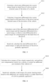
FIG. 1 is a flowchart of a pull drift compensation control method according toEmbodiment 1 of this application; -
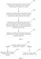
FIG. 2 is a flowchart of S300 in the pull drift compensation control method according toEmbodiment 1 of this application; -
FIG. 3 is a flowchart of S310 in the pull drift compensation control method according toEmbodiment 1 of this application; -
FIG. 4 is a flowchart of S400 in the pull drift compensation control method according toEmbodiment 1 of this application; -
FIG. 5 is a flowchart of S420 in the pull drift compensation control method according toEmbodiment 1 of this application; -
FIG. 6 is a flowchart before S200 in the pull drift compensation control method according toEmbodiment 1 of this application; -
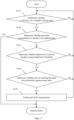
FIG. 7 is a flowchart of S100 in the pull drift compensation control method according toEmbodiment 1 of this application; -
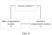
FIG. 8 is a schematic diagram of modules of a pull drift compensation assist system according to Embodiment 2 of this application; -
FIG. 9 is a schematic working diagram of the pull drift compensation assist system according to Embodiment 2 of this application; and -
FIG. 10 is a diagram of a system architecture of an electronic device according to Embodiment 3 of this application. - 10: in-vehicle electronic control system; 11: control module; 12: main compensation module; 13: auxiliary compensation module; 14: drive motor; 15: steering gear; 16: power steering motor; 20: signal collection and estimation module; 30: execution apparatus.
- Terms used in embodiments of this application are merely for the purpose of describing specific embodiments, but are not intended to limit this application. The terms "a/an", "the" and "this" of singular forms used in embodiments and the appended claims of this application are also intended to include plural forms, unless otherwise specified in the context clearly.
-
Embodiment 1 of this application discloses a pull drift compensation control method, to resolve technical problems of a small compensation range, motor blocking, no redundancy control, and the like of an existing pull drift compensation technology. - As shown in
FIG. 1 , the pull drift compensation control method includes the following steps. - S200: Determine status information of differential drive assist steering.
- S300: When differential drive assist steering works, perform pull drift compensation through differential drive assist steering.
- S400: When differential drive assist steering fails, perform pull drift compensation through electric power steering.
- In S200, differential drive assist steering is used as a main system, and electric power steering is used as an auxiliary system. The main system and the auxiliary system are mainly switched by determining, based on the status information of differential drive assist steering, whether pull drift compensation control is implemented through differential drive assist steering of the main system or through electric power steering of the auxiliary system. Differential drive assist steering is a new assisted steering technology in which steering power is provided by using a differential torque of left and right front wheels. Differential control of left and right wheels may be implemented based on an operation performed by a driver on a steering wheel, to generate a differential drive assist torque, and corresponding steering power is provided based on a requirement of the driver. An assist characteristic of differential drive assist steering that power varies with a speed also determines a tradeoff between assisted steering and road sense maintenance. When no fault (for example, a drive motor fault) occurs on differential drive assist steering, pull drift compensation control is implemented through differential drive assist steering of the main system; or when differential drive assist steering is faulty, pull drift compensation control is implemented through electric power steering of the auxiliary system.
- In S300 and S400, torques of drive motors and a torque of a power steering motor, that are required for compensating for hand force of the driver, are mainly calculated. A working principle of differential drive assist steering of the main system is different from that of electric power steering of the auxiliary system, so that calculation methods for the compensation torques are also different. The following describes differential drive assist steering and electric power steering in detail respectively.
- As shown in
FIG. 2 , S300 in the pull drift compensation control method inEmbodiment 1 includes the following steps. - S310: Iteratively calculate a total differential drive assist torque, to make the hand force of the driver gradually approach 0.
- S320: Calculate drive torques of two front wheels based on the total differential drive assist torque.
- S330: Perform yaw compensation control on a vehicle based on the total differential drive assist torque, to control an additional yaw moment of the vehicle to 0, and calculate drive torques of two rear wheels.
- As shown in
FIG. 3 , S310 in the pull drift compensation control method inEmbodiment 1 includes the following steps. - S311: Calculate a short-term differential drive assist torque based on the hand force of the driver and an external cause of deviation of the vehicle.
- S312: Calculate a long-term differential drive assist torque based on the hand force of the driver and an internal cause of the deviation of the vehicle.
- S313: Calculate a sum of the short-term differential drive assist torque and the long-term differential drive assist torque, to obtain the total differential drive assist torque for compensating for the hand force of the driver.
- S314: Iteratively calculate the total differential drive assist torque, to make the hand force of the driver gradually approach 0.
- With reference to
FIG. 2 andFIG. 3 , in S300, pull drift compensation is performed through differential drive assist steering, which is implemented based on the hand force of the driver by controlling four drive motors. - First, in step S310, the differential drive assist torque required for pull drift compensation control is calculated based on the hand force of the driver when the vehicle runs straight. Deviation of the vehicle is caused by an internal factor (for example, a suspension, tire wear, and a wheel positioning parameter) and an external factor (for example, cross wind and an inclined road surface). The required differential drive assist torque needs to be calculated for the internal factor and the external factor respectively. For deviation caused by the external factor, a required short-term differential drive assist torque ΔTDS is mainly calculated through short-term compensation based on the hand force Th of the driver. ΔTDS slowly decreases to 0 after pull drift compensation is stopped, and also slowly decreases to 0 when the system is powered off. Time when short-term compensation tends to be stable may be controlled by adjusting a value of a short-term compensation iteration coefficient CS. A specific calculation method for the short-term differential drive assist torque ΔTDS is shown in the following formula:

- In the formula, z indicates a current moment, and z - 1 indicates a previous moment.
- For deviation caused by the internal factor, a required long-term differential drive assist torque ΔTDL is mainly calculated through long-term compensation based on the hand force Th of the driver and a short-term differential drive assist torque ΔTDS . When pull drift compensation is stopped, ΔTDL remains a value at the previous moment. When the system is powered off, the value is stored as an initial value of long-term compensation in a next power-on cycle. Time when long-term compensation tends to be stable may be controlled by adjusting a value of a long-term compensation iteration coefficient CL. The time when long-term compensation tends to be stable should be greater than time when short-term compensation tends to be stable. A specific calculation method for the long-term differential drive assist torque ΔTDL is shown in the following formula:

- A sum of the short-term differential drive assist torque ΔTDS and the long-term differential drive assist torque ΔTDL is a total differential drive assist torque ΔTD required for compensating for the hand force of the driver. A specific calculation method is shown in the following formula:

- Iterative calculation is performed continuously according to the formula for calculating the differential drive assist torque until the hand force of the driver approaches 0.
- In step S320, drive torques of drive motors of the two front wheels are calculated based on the total differential drive assist torque ΔTD . Specific calculation formulas are as follows:
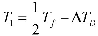

- In the formulas, Tf indicates a front axle drive torque, and T 1 and T 2 indicate a drive torque of a left front wheel and a drive torque of a right front wheel.
- In step S330, yaw compensation control is performed on the entire vehicle based on the total differential drive assist torque ΔTD . When differential drive assist steering compensates for the hand force of the driver by using the total differential drive assist torque ΔTD, the additional yaw moment is also formed for the entire vehicle. However, an expected yaw rate of the vehicle in a straight running process is 0. Therefore, the drive torques of the rear wheels need to be controlled, to offset the additional yaw moment formed by the front wheels. To control the additional yaw moment of the entire vehicle to 0, the drive torques of the rear wheels need to satisfy the following conditions:


- In the formulas, Tr indicates a rear axle drive torque, and T 3 and T 4 indicate a drive torque of a left rear wheel and a drive torque of a right rear wheel. After the foregoing conditions are satisfied, the drive torques of the rear wheels may further be calculated as follows:


- In a process of performing pull drift compensation control through differential drive assist steering, the torque of the power steering motor is controlled to 0.
- As shown in
FIG. 4 , S400 in the pull drift compensation control method inEmbodiment 1 includes the following steps. - S410: Calculate drive torques of four wheels respectively, and perform yaw compensation control on a vehicle, to control an additional yaw moment of the vehicle to 0.
- S420: Iteratively calculate a total torque of the power steering motor based on the additional yaw moment being 0, to make the hand force of the driver gradually approach 0.
- As shown in
FIG. 5 , S420 in the pull drift compensation control method inEmbodiment 1 includes the following steps. - S421: Calculate a short-term torque of the power steering motor based on the hand force of the driver and an external cause of deviation of the vehicle.
- S422: Calculate a long-term torque of the power steering motor based on the hand force of the driver and an internal cause of the deviation of the vehicle.
- S423: Calculate a sum of the short-term torque of the power steering motor and the long-term torque of the power steering motor, to obtain the total torque of the power steering motor for compensating for the hand force of the driver.
- S424: Iteratively calculate the total torque of the power steering motor, to make the hand force of the driver gradually approach 0.
- In S400, when differential drive assist steering fails for a specific cause (for example, a drive motor fault), pull drift compensation control is performed through electric power steering by controlling the power steering motor based on the hand force of the driver.
- When pull drift compensation control is performed through electric power steering, a yaw rate of the vehicle needs to be first ensured to be 0. In addition, if drive torques of the two front wheels are different, additional steering power may be generated, which affects the hand force applied by the driver on the steering wheel. Therefore, before the torque of the power steering motor is calculated, yaw compensation control needs to be performed on the vehicle first. Based on this, the torque of the power steering motor is iteratively calculated by considering impact of an internal factor, an external factors, and yaw compensation control until the hand force of the driver approaches 0.
- In step S410, yaw compensation control is first performed on the vehicle, to control the additional yaw moment of the entire vehicle to 0. In this case, the drive torques of the four wheels need to satisfy the following constraint conditions:


- Specifically, the drive torques of the four wheels may further be obtained through calculation with reference to another vehicle dynamic control function. For example, if a motor of a left front wheel is faulty, the drive torques of the four wheels may be obtained as follows:


- After yaw compensation control is performed on the entire vehicle, in step S420, the torque of the power steering motor that is required for pull drift compensation control is calculated based on the hand force of the driver when the vehicle runs straight. The required torque of the power steering motor needs to be calculated for the internal factor and the external factor that cause deviation of the vehicle respectively. For deviation caused by the external factor, a required short-term torque TES of the power steering motor is mainly calculated through short-term compensation based on the hand force Th of the driver. TES slowly decreases to 0 after pull drift compensation is stopped, and also slowly decreases to 0 when the system is powered off. Time when short-term compensation tends to be stable may be controlled by adjusting a value of a short-term compensation iteration coefficient CS. A specific calculation method for the short-term torque TES of the power steering motor is shown in the following formula:

- For deviation caused by the internal factor, a required long-term torque TEL of the power steering motor is mainly calculated through long-term compensation based on the hand force Th of the driver and a short-term torque TES of the power steering motor. When pull drift compensation is stopped, TEL remains a value at a previous moment. When the system is powered off, the value is stored as an initial compensation value of long-term compensation in a next power-on cycle. Time when long-term compensation tends to be stable may be controlled by adjusting a value of a long-term compensation iteration coefficient CL. The time when long-term compensation tends to be stable should be greater than time when short-term compensation tends to be stable. A specific calculation method for the long-term torque TEL of the power steering motor is shown in the following formula:

- A sum of the short-term torque TES of the power steering motor and the long-term torque TEL of the power steering motor is a total torque TE of the power steering motor that is required for compensating for the hand force of the driver. A specific calculation method is shown in the following formula:

- Iterative calculation is performed continuously according to the formula for calculating the torque of the power steering motor until the hand force of the driver approaches 0.
- As shown in
FIG. 6 , before S200, the pull drift compensation control method inEmbodiment 1 includes the following step. - S100: Determine whether pull drift compensation is enabled.
- If pull drift compensation is enabled, S200 is performed to determine the status information of differential drive assist steering.
- If pull drift compensation is disabled, S200' is performed to control, by using a vehicle control unit, a vehicle to run.
- As shown in
FIG. 7 ,S 100 in the pull drift compensation control method inEmbodiment 1 includes the following steps. - S110: Determine whether the vehicle is in a straight running state. If the vehicle is not in the straight running state, step S110 is performed; or if the vehicle is in the straight running state, step S120 is performed.
- S120: Determine whether pull drift compensation is already in an enabled state.
- If pull drift compensation is already in the enabled state, S200 is performed to determine the status information of differential drive assist steering.
- If pull drift compensation is not in the enabled state, S130 is performed to determine whether the hand force of the driver reaches a preset hand force threshold.
- If the hand force of the driver reaches the preset hand force threshold, S140 is performed to determine whether time of reaching the hand force threshold reaches preset time.
- If the time of reaching the hand force threshold reaches the preset time, S150 is performed to enable pull drift compensation, and S200 is performed to determine the status information of differential drive assist steering.
- First, step S110 is performed to determine whether the vehicle is in the straight running state. If the vehicle is not in the straight running state, step S110 is performed; or if the vehicle is in the straight running state, step S120 is performed. Conditions for determining whether the vehicle is in the straight running state are as follows:
- (1) a vehicle speed≥u 0;
- (2) a steering wheel angle≤δ 0, and a steering wheel speed≤δ̇ 0;
- (3) a longitudinal accelerations≤a x0;
- (4) a lateral acceleration≤a y0; and
- (5) a yaw rate of a center of mass of the vehicle≤ω r0.
- It is determined that the vehicle is in the straight running state only when the foregoing five conditions are satisfied. u 0, δ 0, δ̇ 0, a x0, a y0, and ω r0 indicate a vehicle speed threshold, a steering wheel angle threshold, a steering wheel speed threshold, a longitudinal acceleration threshold, a lateral acceleration threshold, and a yaw rate threshold.
- In step S120, whether pull drift compensation is already enabled is determined. If pull drift compensation is already enabled, S200 is performed; or if pull drift compensation is disabled, step S130 is performed.
- In step S130, whether the hand force of the driver reaches the hand force threshold T h0 is determined. If the hand force of the driver does not reach the hand force threshold,
step S 110 is performed; or if the hand force of the driver reaches the hand force threshold, step S140 is performed. - In step S140, timing is started when the hand force of the driver is greater than the hand force threshold T h0. When timing time is greater than a time threshold t, step S150 is performed; or if timing time is not greater than a time threshold, step S110 is performed.
- In step S150, a pull drift compensation enable signal is sent, step S200 is performed, and in addition, step S110 is performed, to start a new round of pull drift compensation enable determining.
- As shown in
FIG. 8 , Embodiment 2 of this application discloses a pull drift compensation assist system, including acontrol module 11, amain compensation module 12, and anauxiliary compensation module 13 that communicate with each other. - The
control module 11 is configured to determine status information of differential drive assist steering. When differential drive assist steering works, themain compensation module 12 is configured to control, through thecontrol module 11, pull drift compensation to be performed through differential drive assist steering; when differential drive assist steering fails, theauxiliary compensation module 13 is configured to control, through thecontrol module 11, pull drift compensation to be performed through electric power steering. - In the pull drift compensation assist system in Embodiment 2, the
control module 11 is connected to drivemotors 14 of four wheels of a vehicle, and is connected to apower steering motor 16 connected to asteering gear 15 of the vehicle. When themain compensation module 12 is started, thecontrol module 11 controls the fourdrive motors 14 to perform pull drift compensation; or when theauxiliary compensation module 13 is started, thecontrol module 11 controls thepower steering motor 16 to perform pull drift compensation. - As shown in
FIG. 9 , the pull drift compensation assist system in Embodiment 2 is mainly used in a scenario in which the vehicle runs straight, to compensate for hand force of a driver. This dual-redundancy pull drift compensation assist system mainly includes a motor control unit (MCU, Motor Control Unit) (that is, the control module 11), differential drive assist steering (that is, the main compensation module 12), and electric power steering (that is, the auxiliary compensation module 13). Differential drive assist steering (that is, the main compensation module 12) and electric power steering (that is, the auxiliary compensation module 13) form a main/auxiliary redundant pull drift compensation system. Pull drift compensation control is performed through differential drive assist steering by controlling thedrive motors 14 of the four wheels. Pull drift compensation control is performed through electric power steering by controlling thepower steering motor 16. Information exchange may be performed between any two of differential drive assist steering, electric power steering, and the motor control unit. Differential drive assist steering and electric power steering send drive torque instructions of the fourdrive motors 14 and torque instructions of thepower steering motor 16 to the motor control unit. The motor control unit controls thedrive motors 14 and thepower steering motor 16, to compensate for the hand force of the driver. - As shown in
FIG. 10 , Embodiment 3 of this application discloses an electronic device, including an in-vehicleelectronic control system 10, a signal collection andestimation module 20, and anexecution apparatus 30. The in-vehicleelectronic control system 10 has the pull drift compensation assist system in Embodiment 2 of this application. The signal collection andestimation module 20 has a plurality of vehicle status sensors configured to measure vehicle status parameters. Theexecution apparatus 30 has the drive motors and the power steering motor in Embodiment 2 of this application. - The signal collection and
estimation module 20 sends a plurality of vehicle status parameters collected by the plurality of vehicle status sensors to the in-vehicleelectronic control system 10. The in-vehicleelectronic control system 10 controls the drive motors and the power steering motor based on the plurality of vehicle status parameters, so that the electronic device performs the pull drift compensation control method inEmbodiment 1. - Specifically, the electronic device in Embodiment 3 mainly includes three parts: the in-vehicle
electronic control system 10, the signal collection andestimation module 20, and theexecution apparatus 30. The in-vehicleelectronic control system 10 mainly includes electric power steering (that is, the auxiliary compensation module 13), a vehicle control unit (VCU, Vehicle Control Unit), the motor control unit (that is, the control module 11), and the like. Control logic of differential drive assist steering is generally set in the vehicle control unit, that is, the vehicle control unit has themain compensation module 12. The signal collection andestimation module 20 mainly includes vehicle speed estimation, a yaw rate sensor, a steering wheel angle sensor, a steering wheel torque sensor, a longitudinal acceleration sensor, and other vehicle status sensors and vehicle parameters. Theexecution apparatus 30 mainly includes thedrive motors 14 and thepower steering motor 16. With reference toFIG. 9 , the signal collection andestimation module 20 transfers a vehicle speed, a steering wheel angle, hand force of a driver (a steering wheel torque), a yaw rate, and other vehicle status information to the in-vehicleelectronic control system 10. In the in-vehicleelectronic control system 10, information exchange is performed between differential drive assist steering, electric power steering, and the motor control unit, to determine a system for pull drift compensation control. If pull drift compensation control is performed through differential drive assist steering, a torque of the power steering motor is controlled to 0, and torques of the drive motors are further calculated; or if pull drift compensation control is performed through electric power steering, torques of the drive motors and a torque of the power steering motor are calculated respectively. Finally, the in-vehicleelectronic control system 10 sends torque instructions of the drive motors and torque instructions of the power steering motor to theexecution apparatus 30 such as thedrive motors 14 and thepower steering motor 16 respectively, to implement effective control on a vehicle. - Embodiment 4 of this application further provides a computer-readable storage medium, including program instructions. When the program instructions run on a computer device, the computer device is enabled to perform the pull drift compensation control method as described in the first aspect.
- Compared with the conventional technology, the technical solutions have at least the following beneficial effects.
- According to the pull drift compensation assist system and the control method disclosed in embodiments of this application, compensation can be performed through differential drive assist steering, to effectively reduce occurrence of a long-time motor blocking phenomenon, reduce a motor fault risk, and reduce a motor performance deterioration degree. Compensation through differential drive assist steering may expand a hand force compensation range. Main/auxiliary system redundancy backup of differential drive assist steering and electric power steering may reduce a failure probability of pull drift compensation, and improve running safety of the vehicle. Long-term compensation and short-term compensation are performed concurrently, so that compensation for both deviation caused by an external factor and deviation caused by a factor of the vehicle may be implemented.
- All or some of the foregoing embodiments may be implemented by software, hardware, firmware, or any combination thereof. When software is used to implement the foregoing embodiments, all or some of the foregoing embodiments may be implemented in a form of a computer program product. The computer program product includes one or more computer instructions. When the computer program instructions are loaded and executed on a computer, processes or functions according to this application are all or partially generated. The computer may be a general-purpose computer, a dedicated computer, a computer network, or another programmable apparatus. The computer instructions may be stored in a computer-readable storage medium, or may be transmitted from a computer-readable storage medium to another computer-readable storage medium. For example, the computer instructions may be transmitted from a website, computer, server, or data center to another website, computer, server, or data center in a wired (for example, a coaxial cable, an optical fiber, or a digital subscriber line) or wireless (for example, infrared, radio, or microwave) manner. The computer-readable storage medium may be any usable medium accessible by the computer, or a data storage device, for example, a server or a data center, integrating one or more usable media. The usable medium may be a magnetic medium (for example, a floppy disk, a hard disk, or a magnetic tape), an optical medium (for example, a DVD), a semiconductor medium (for example, a solid state disk, (Solid State Disk)), or the like.
- In the foregoing embodiments, the processor may include, for example, a central processing unit (CPU, central processing unit), a microprocessor, a microcontroller, or a digital signal processor, and may further include a graphics processing unit (GPU, graphics processing unit), a network processor (NPU, Neural-network Processing Unit), and an internet service provider (ISP, Internet Service Provider). The processor may further include a necessary hardware accelerator or logic processing hardware circuit, for example, an application-specific integrated circuit (ASIC, application-specific integrated circuit), or one or more integrated circuits configured to control program execution of the technical solutions of this application. In addition, the processor may have a function of operating one or more software programs, and the software program may be stored in a memory.
- The memory may be but is not limited to a read-only memory (ROM, read-only memory), another type of static storage device capable of storing static information and instructions, a random access memory (RAM, random access memory), or another type of dynamic storage device capable of storing information and instructions, may be an electrically erasable programmable read-only memory (EEPROM, electrically erasable programmable read-only memory), a compact disc read-only memory (CD-ROM, compact disc read-only memory) or another compact disc storage, an optical disc storage (including a compact disc, a laser disc, an optical disc, a digital versatile disc, a Blu-ray disc, and the like), a magnetic disk storage medium, or another magnetic storage device, or may be any other medium that can be used to carry or store expected program code in a form of an instruction or a data structure and that can be accessed by the computer.
- In embodiments of this application, "at least one" means one or more, and "a plurality of" means two or more. The term "and/or" describes an association relationship between associated objects, and indicates that three relationships may exist. For example, A and/or B may indicate the following three cases: Only A exists, both A and B exist, and only B exists. A and B may be singular or plural. The character "/" generally indicates an "or" relationship between the associated objects. "At least one of the following items" or a similar expression thereof means any combination of these items, including a single item or any combination of a plurality of items. For example, at least one of a, b, and c may indicate: a, b, c, a-b, a-c, b-c, or a-b-c, where a, b, and c may be singular or plural.
- A person of ordinary skill in the art may be aware that the units and algorithm steps described in embodiments disclosed in this specification can be implemented by electronic hardware or a combination of computer software and electronic hardware. Whether the functions are performed by hardware or software depends on particular applications and design constraints of the technical solutions. A person skilled in the art may use different methods to implement the described functions for each particular application, but it should not be considered that the implementation goes beyond the scope of this application.
- It may be clearly understood by a person skilled in the art that, for the purpose of convenient and brief description, for a detailed working process of the foregoing system, apparatus, and unit, reference may be made to a corresponding process in the foregoing method embodiment, and details are not described again herein.
- In embodiments of this application, when any of the functions is implemented in a form of a software function unit and sold or used as an independent product, the function may be stored in a computer-readable storage medium. Based on such an understanding, the technical solutions of this application essentially, or the part contributing to the conventional technology, or some of the technical solutions may be implemented in a form of a software product. The computer software product is stored in a storage medium, and includes several instructions for instructing a computer device (which may be a personal computer, a server, a network device, or the like) to perform all or some of the steps of the method described in embodiments of this application. The foregoing storage medium includes any medium capable of storing program code, such as a USB flash drive, a removable hard disk, a read-only memory, a random access memory, a magnetic disk, or an optical disc. The foregoing descriptions are merely specific implementations of the present invention, but are not intended to limit the protection scope of the present invention. Any variation or replacement readily figured out by a person skilled in the art within the technical scope disclosed in the present invention shall fall within the protection scope of the present invention. Therefore, the protection scope of the present invention shall be subject to the protection scope of the claims.
Claims (11)
- A pull drift compensation control method, comprising:determining status information of differential drive assist steering; andwhen differential drive assist steering works, performing pull drift compensation through differential drive assist steering; orwhen differential drive assist steering fails, performing pull drift compensation through electric power steering.
- The pull drift compensation control method according to claim 1, wherein the step of performing pull drift compensation through differential drive assist steering comprises:iteratively calculating a total differential drive assist torque, to make hand force of a driver gradually approach 0;calculating drive torques of two front wheels based on the total differential drive assist torque; andperforming yaw compensation control on a vehicle based on the total differential drive assist torque, to control an additional yaw moment of the vehicle to 0, and calculating drive torques of two rear wheels.
- The pull drift compensation control method according to claim 2, wherein the step of iteratively calculating a total differential drive assist torque, to make hand force of a driver gradually approach 0 comprises:calculating a short-term differential drive assist torque based on the hand force of the driver and an external cause of deviation of the vehicle;calculating a long-term differential drive assist torque based on the hand force of the driver and an internal cause of the deviation of the vehicle;calculating a sum of the short-term differential drive assist torque and the long-term differential drive assist torque, to obtain the total differential drive assist torque for compensating for the hand force of the driver; anditeratively calculating the total differential drive assist torque, to make the hand force of the driver gradually approach 0.
- The pull drift compensation control method according to claim 1, wherein the step of performing pull drift compensation through electric power steering comprises:calculating drive torques of four wheels respectively, and performing yaw compensation control on a vehicle, to control an additional yaw moment of the vehicle to 0; anditeratively calculating a total torque of a power steering motor based on the additional yaw moment being 0, to make hand force of a driver gradually approach 0.
- The pull drift compensation control method according to claim 4, wherein the step of iteratively calculating a total torque of a power steering motor based on the additional yaw moment being 0, to make hand force of a driver gradually approach 0 comprises:calculating a short-term torque of the power steering motor based on the hand force of the driver and an external cause of deviation of the vehicle;calculating a long-term torque of the power steering motor based on the hand force of the driver and an internal cause of the deviation of the vehicle;calculating a sum of the short-term torque of the power steering motor and the long-term torque of the power steering motor, to obtain the total torque of the power steering motor for compensating for the hand force of the driver; anditeratively calculating the total torque of the power steering motor, to make the hand force of the driver gradually approach 0.
- The pull drift compensation control method according to claim 1, wherein before the step of determining status information of differential drive assist steering, the pull drift compensation control method comprises:determining whether pull drift compensation is enabled; andif pull drift compensation is enabled, determining the status information of differential drive assist steering; orif pull drift compensation is disabled, controlling pull drift compensation of a vehicle by using a motor control unit of the vehicle.
- The pull drift compensation control method according to claim 6, wherein the step of determining whether pull drift compensation is enabled comprises:determining whether the vehicle is in a straight running state;determining whether pull drift compensation is already in an enabled state; andif pull drift compensation is already in the enabled state, determining the status information of differential drive assist steering; orif pull drift compensation is not in the enabled state, determining whether hand force of a driver reaches a preset hand force threshold;if the hand force of the driver reaches the preset hand force threshold, determining whether time of reaching the hand force threshold reaches preset time; andif the time of reaching the hand force threshold reaches the preset time, enabling pull drift compensation, and determining the status information of differential drive assist steering.
- A pull drift compensation assist system, comprising a control module, a main compensation module, and an auxiliary compensation module that communicate with each other, whereinthe control module is configured to determine status information of differential drive assist steering; andwhen differential drive assist steering works, the main compensation module is configured to control, through the control module, pull drift compensation to be performed through differential drive assist steering;when differential drive assist steering fails, the auxiliary compensation module is configured to control, through the control module, pull drift compensation to be performed through electric power steering.
- The pull drift compensation assist system according to claim 8, wherein the control module is connected to drive motors of four wheels of a vehicle, and is connected to a power steering motor connected to a steering gear of the vehicle; andwhen the main compensation module is started, the control module controls the four drive motors to perform pull drift compensation;when the auxiliary compensation module is started, the control module controls the power steering motor to perform pull drift compensation.
- An electronic device, comprising an in-vehicle electronic control system, a signal collection and estimation module, and an execution apparatus, wherein the in-vehicle electronic control system has the pull drift compensation assist system according to claim 8 or 9, the signal collection and estimation module has a plurality of vehicle status sensors configured to measure vehicle status parameters, and the execution apparatus has the drive motors and the power steering motor according to claim 9; and
the signal collection and estimation module sends a plurality of vehicle status parameters collected by the plurality of vehicle status sensors to the in-vehicle electronic control system, and the in-vehicle electronic control system controls the drive motors and the power steering motor based on the plurality of vehicle status parameters, so that the electronic device performs the pull drift compensation control method according to any one of claims 1 to 7. - A computer-readable storage medium, comprising program instructions, wherein when the program instructions run on a computer device, the computer device is enabled to perform the pull drift compensation control method according to any one of claims 1 to 7.
Applications Claiming Priority (1)
| Application Number | Priority Date | Filing Date | Title |
|---|---|---|---|
| PCT/CN2021/125550 WO2023065278A1 (en) | 2021-10-22 | 2021-10-22 | Pull drift compensation assist system and control method |
Publications (3)
| Publication Number | Publication Date |
|---|---|
| EP4393791A1 true EP4393791A1 (en) | 2024-07-03 |
| EP4393791A4 EP4393791A4 (en) | 2024-10-16 |
| EP4393791B1 EP4393791B1 (en) | 2026-04-29 |
Family
ID=86058742
Family Applications (1)
| Application Number | Title | Priority Date | Filing Date |
|---|---|---|---|
| EP21961027.6A Active EP4393791B1 (en) | 2021-10-22 | 2021-10-22 | Pull drift compensation assist system and control method |
Country Status (3)
| Country | Link |
|---|---|
| EP (1) | EP4393791B1 (en) |
| CN (1) | CN116457260B (en) |
| WO (1) | WO2023065278A1 (en) |
Cited By (1)
| Publication number | Priority date | Publication date | Assignee | Title |
|---|---|---|---|---|
| DE102024202534A1 (en) * | 2024-03-19 | 2025-09-25 | Zf Friedrichshafen Ag | Method and driver assistance system for compensating for crosswinds |
Families Citing this family (4)
| Publication number | Priority date | Publication date | Assignee | Title |
|---|---|---|---|---|
| CN117208074A (en) * | 2023-09-27 | 2023-12-12 | 中国第一汽车股份有限公司 | Compensation control method, device, processor and vehicle for vehicle deviation |
| CN118082966B (en) * | 2024-02-27 | 2025-10-14 | 厦门金龙联合汽车工业有限公司 | Adaptive compensation algorithm for commercial vehicle power steering based on model predictive control |
| CN117901841B (en) * | 2024-02-27 | 2025-08-22 | 大陆软件系统开发中心(重庆)有限公司 | Vehicle yaw moment compensation method and device |
| CN119705601B (en) * | 2025-01-20 | 2025-12-19 | 重庆长安汽车股份有限公司 | Vehicle pull-off suppression methods, devices, electronic equipment and storage media |
Family Cites Families (16)
| Publication number | Priority date | Publication date | Assignee | Title |
|---|---|---|---|---|
| JPH0796370B2 (en) * | 1986-03-07 | 1995-10-18 | 富士重工業株式会社 | Rear wheel torque distribution control device for vehicle |
| JP4613668B2 (en) * | 2005-04-01 | 2011-01-19 | 日産自動車株式会社 | Vehicle behavior control apparatus and vehicle behavior control method |
| GB2437503A (en) * | 2006-04-24 | 2007-10-31 | Advanced Transp Systems Ltd | Steering arrangement using differing drive torques |
| JP5741394B2 (en) * | 2011-11-15 | 2015-07-01 | 株式会社デンソー | Electric power steering control device |
| DE102011121117B4 (en) * | 2011-12-14 | 2018-02-01 | Audi Ag | Method for crosswind stabilization of a motor vehicle and motor vehicle comprising front and rear wheels and a device for detecting a side shelf |
| DE102014204461B4 (en) * | 2013-05-14 | 2018-10-31 | Ford Global Technologies, Llc | Method for improving the straight-line stability of a vehicle |
| CN104401392B (en) * | 2014-09-28 | 2016-08-17 | 奇瑞汽车股份有限公司 | A kind of running out the way correction for direction system and method |
| EP3090907B1 (en) * | 2015-05-05 | 2020-08-12 | Volvo Car Corporation | Secondary steering system unit, secondary steering system, vehicle and a method for secondary steering |
| CN105015616A (en) * | 2015-06-29 | 2015-11-04 | 湖南大学 | Control method of power steering for lane departure driving assistance |
| US9944314B2 (en) * | 2016-04-13 | 2018-04-17 | Ford Global Technologies, Llc | Steering assist system and related methods |
| CN106741138B (en) * | 2016-12-16 | 2019-02-19 | 吉林大学 | A multi-mode steering system and control method of an electric wheel drive vehicle |
| CN108163044A (en) * | 2017-12-11 | 2018-06-15 | 同济大学 | The steering redundancy of four motorized wheels electric vehicle and integrated control system and method |
| CN108177688B (en) * | 2018-01-03 | 2019-10-22 | 吉林大学 | A hydraulic hub motor assisted differential power steering control method |
| CN108657270B (en) * | 2018-06-11 | 2023-08-15 | 南京航空航天大学 | A vehicle steering-by-wire system, a fault-tolerant control method, and a fault diagnosis method |
| CN111731315B (en) * | 2019-03-25 | 2021-12-31 | 博世华域转向系统有限公司 | Deviation compensation method in automobile rapid acceleration process |
| CN110316247B (en) * | 2019-07-25 | 2021-04-27 | 辽宁工业大学 | A steering control method for electric assist differential compensation for four-wheel independent drive electric vehicles |
-
2021
- 2021-10-22 WO PCT/CN2021/125550 patent/WO2023065278A1/en not_active Ceased
- 2021-10-22 CN CN202180007734.0A patent/CN116457260B/en active Active
- 2021-10-22 EP EP21961027.6A patent/EP4393791B1/en active Active
Cited By (1)
| Publication number | Priority date | Publication date | Assignee | Title |
|---|---|---|---|---|
| DE102024202534A1 (en) * | 2024-03-19 | 2025-09-25 | Zf Friedrichshafen Ag | Method and driver assistance system for compensating for crosswinds |
Also Published As
| Publication number | Publication date |
|---|---|
| EP4393791B1 (en) | 2026-04-29 |
| EP4393791A4 (en) | 2024-10-16 |
| CN116457260A (en) | 2023-07-18 |
| WO2023065278A1 (en) | 2023-04-27 |
| CN116457260B (en) | 2026-02-10 |
Similar Documents
| Publication | Publication Date | Title |
|---|---|---|
| EP4393791B1 (en) | Pull drift compensation assist system and control method | |
| US7913803B2 (en) | Vehicular steering apparatus with capability of providing suitable steering angle correction and power assistance | |
| US12479498B2 (en) | Control method and apparatus | |
| CN114261252B (en) | Active stabilizer bar control method, device, equipment and medium | |
| US8670905B2 (en) | Vehicle stability control method and system | |
| CN113386858A (en) | EPS corner sensor angle neutral position correction self-learning method and system and vehicle | |
| US10131378B2 (en) | Electric power steering apparatus | |
| JP5146540B2 (en) | Steering control device | |
| JP2004001590A (en) | Steering gear | |
| KR20220037538A (en) | Apparatus and method for improving motion performance of turning vehicle | |
| US9278697B2 (en) | Vehicle running control apparatus and method | |
| CN115431955B (en) | Vehicle control method, device, vehicle, and storage medium | |
| JP5251177B2 (en) | Vehicle running state estimation device | |
| WO2025190354A1 (en) | Adhesion coefficient determination method and apparatus, and vehicle, medium and program product | |
| CN117719347B (en) | Vehicle stationary steering control method, device, vehicle and storage medium | |
| CN121291403A (en) | A vehicle control method and device based on rear-wheel steering | |
| JP5251176B2 (en) | Vehicle running state estimation device | |
| CN118494487B (en) | Vehicle torque distribution method, device, vehicle and computer-readable storage medium | |
| JP6900877B2 (en) | Steering by wire system | |
| KR20110080758A (en) | Steering Control Method of Active Front Wheel Steering System | |
| JP4887721B2 (en) | Vehicle running state estimation device | |
| CN119503007B (en) | Vehicle control methods, devices and vehicles | |
| CN118922341A (en) | Driving support method and driving support device | |
| CN120245951B (en) | A method, apparatus, device, and readable storage medium for controlling synchronized wheel slip of vehicles. | |
| CN120863366B (en) | Dynamic boundary layer-based hub motor torque distribution strategy |
Legal Events
| Date | Code | Title | Description |
|---|---|---|---|
| STAA | Information on the status of an ep patent application or granted ep patent |
Free format text: STATUS: THE INTERNATIONAL PUBLICATION HAS BEEN MADE |
|
| PUAI | Public reference made under article 153(3) epc to a published international application that has entered the european phase |
Free format text: ORIGINAL CODE: 0009012 |
|
| STAA | Information on the status of an ep patent application or granted ep patent |
Free format text: STATUS: REQUEST FOR EXAMINATION WAS MADE |
|
| 17P | Request for examination filed |
Effective date: 20240326 |
|
| AK | Designated contracting states |
Kind code of ref document: A1 Designated state(s): AL AT BE BG CH CY CZ DE DK EE ES FI FR GB GR HR HU IE IS IT LI LT LU LV MC MK MT NL NO PL PT RO RS SE SI SK SM TR |
|
| A4 | Supplementary search report drawn up and despatched |
Effective date: 20240918 |
|
| RIC1 | Information provided on ipc code assigned before grant |
Ipc: B60W 10/08 20060101ALI20240912BHEP Ipc: B60W 40/114 20120101ALI20240912BHEP Ipc: B62D 5/04 20060101AFI20240912BHEP |
|
| RAP1 | Party data changed (applicant data changed or rights of an application transferred) |
Owner name: SHENZHEN YINWANG INTELLIGENTTECHNOLOGIES CO., LTD. |
|
| DAV | Request for validation of the european patent (deleted) | ||
| DAX | Request for extension of the european patent (deleted) | ||
| GRAP | Despatch of communication of intention to grant a patent |
Free format text: ORIGINAL CODE: EPIDOSNIGR1 |
|
| STAA | Information on the status of an ep patent application or granted ep patent |
Free format text: STATUS: GRANT OF PATENT IS INTENDED |
|
| INTG | Intention to grant announced |
Effective date: 20251223 |
|
| GRAS | Grant fee paid |
Free format text: ORIGINAL CODE: EPIDOSNIGR3 |
|
| GRAA | (expected) grant |
Free format text: ORIGINAL CODE: 0009210 |
|
| STAA | Information on the status of an ep patent application or granted ep patent |
Free format text: STATUS: THE PATENT HAS BEEN GRANTED |
|
| AK | Designated contracting states |
Kind code of ref document: B1 Designated state(s): AL AT BE BG CH CY CZ DE DK EE ES FI FR GB GR HR HU IE IS IT LI LT LU LV MC MK MT NL NO PL PT RO RS SE SI SK SM TR |
|
| REG | Reference to a national code |
Ref country code: CH Ref legal event code: F10 Free format text: ST27 STATUS EVENT CODE: U-0-0-F10-F00 (AS PROVIDED BY THE NATIONAL OFFICE) Effective date: 20260429 Ref country code: GB Ref legal event code: FG4D |
|
| REG | Reference to a national code |
Ref country code: CH Ref legal event code: W10 Free format text: ST27 STATUS EVENT CODE: U-0-0-W10-W00 (AS PROVIDED BY THE NATIONAL OFFICE) Effective date: 20260507 |