EP4393775A1 - Side window encapsulation mechanism, side window encapsulation glass assembly, and automobile - Google Patents
Side window encapsulation mechanism, side window encapsulation glass assembly, and automobile Download PDFInfo
- Publication number
- EP4393775A1 EP4393775A1 EP22871984.5A EP22871984A EP4393775A1 EP 4393775 A1 EP4393775 A1 EP 4393775A1 EP 22871984 A EP22871984 A EP 22871984A EP 4393775 A1 EP4393775 A1 EP 4393775A1
- Authority
- EP
- European Patent Office
- Prior art keywords
- encapsulation
- sidewall
- side window
- disposed
- hole
- Prior art date
- Legal status (The legal status is an assumption and is not a legal conclusion. Google has not performed a legal analysis and makes no representation as to the accuracy of the status listed.)
- Granted
Links
Images



Classifications
-
- B—PERFORMING OPERATIONS; TRANSPORTING
- B60—VEHICLES IN GENERAL
- B60Q—ARRANGEMENT OF SIGNALLING OR LIGHTING DEVICES, THE MOUNTING OR SUPPORTING THEREOF OR CIRCUITS THEREFOR, FOR VEHICLES IN GENERAL
- B60Q3/00—Arrangement of lighting devices for vehicle interiors; Lighting devices specially adapted for vehicle interiors
- B60Q3/20—Arrangement of lighting devices for vehicle interiors; Lighting devices specially adapted for vehicle interiors for lighting specific fittings of passenger or driving compartments; mounted on specific fittings of passenger or driving compartments
- B60Q3/208—Sun roofs; Windows
-
- B—PERFORMING OPERATIONS; TRANSPORTING
- B60—VEHICLES IN GENERAL
- B60J—WINDOWS, WINDSCREENS, NON-FIXED ROOFS, DOORS, OR SIMILAR DEVICES FOR VEHICLES; REMOVABLE EXTERNAL PROTECTIVE COVERINGS SPECIALLY ADAPTED FOR VEHICLES
- B60J1/00—Windows; Windscreens; Accessories therefor
- B60J1/08—Windows; Windscreens; Accessories therefor arranged at vehicle sides
-
- B—PERFORMING OPERATIONS; TRANSPORTING
- B60—VEHICLES IN GENERAL
- B60Q—ARRANGEMENT OF SIGNALLING OR LIGHTING DEVICES, THE MOUNTING OR SUPPORTING THEREOF OR CIRCUITS THEREFOR, FOR VEHICLES IN GENERAL
- B60Q1/00—Arrangement of optical signalling or lighting devices, the mounting or supporting thereof or circuits therefor
- B60Q1/26—Arrangement of optical signalling or lighting devices, the mounting or supporting thereof or circuits therefor the devices being primarily intended to indicate the vehicle, or parts thereof, or to give signals, to other traffic
- B60Q1/2661—Arrangement of optical signalling or lighting devices, the mounting or supporting thereof or circuits therefor the devices being primarily intended to indicate the vehicle, or parts thereof, or to give signals, to other traffic mounted on parts having other functions
- B60Q1/268—Arrangement of optical signalling or lighting devices, the mounting or supporting thereof or circuits therefor the devices being primarily intended to indicate the vehicle, or parts thereof, or to give signals, to other traffic mounted on parts having other functions on windscreens or windows
-
- B—PERFORMING OPERATIONS; TRANSPORTING
- B60—VEHICLES IN GENERAL
- B60J—WINDOWS, WINDSCREENS, NON-FIXED ROOFS, DOORS, OR SIMILAR DEVICES FOR VEHICLES; REMOVABLE EXTERNAL PROTECTIVE COVERINGS SPECIALLY ADAPTED FOR VEHICLES
- B60J1/00—Windows; Windscreens; Accessories therefor
- B60J1/08—Windows; Windscreens; Accessories therefor arranged at vehicle sides
- B60J1/10—Windows; Windscreens; Accessories therefor arranged at vehicle sides fixedly mounted
-
- B—PERFORMING OPERATIONS; TRANSPORTING
- B60—VEHICLES IN GENERAL
- B60J—WINDOWS, WINDSCREENS, NON-FIXED ROOFS, DOORS, OR SIMILAR DEVICES FOR VEHICLES; REMOVABLE EXTERNAL PROTECTIVE COVERINGS SPECIALLY ADAPTED FOR VEHICLES
- B60J1/00—Windows; Windscreens; Accessories therefor
- B60J1/20—Accessories, e.g. wind deflectors, blinds
-
- B—PERFORMING OPERATIONS; TRANSPORTING
- B60—VEHICLES IN GENERAL
- B60J—WINDOWS, WINDSCREENS, NON-FIXED ROOFS, DOORS, OR SIMILAR DEVICES FOR VEHICLES; REMOVABLE EXTERNAL PROTECTIVE COVERINGS SPECIALLY ADAPTED FOR VEHICLES
- B60J10/00—Sealing arrangements
- B60J10/70—Sealing arrangements specially adapted for windows or windscreens
-
- B—PERFORMING OPERATIONS; TRANSPORTING
- B60—VEHICLES IN GENERAL
- B60Q—ARRANGEMENT OF SIGNALLING OR LIGHTING DEVICES, THE MOUNTING OR SUPPORTING THEREOF OR CIRCUITS THEREFOR, FOR VEHICLES IN GENERAL
- B60Q1/00—Arrangement of optical signalling or lighting devices, the mounting or supporting thereof or circuits therefor
- B60Q1/26—Arrangement of optical signalling or lighting devices, the mounting or supporting thereof or circuits therefor the devices being primarily intended to indicate the vehicle, or parts thereof, or to give signals, to other traffic
- B60Q1/2619—Arrangement of optical signalling or lighting devices, the mounting or supporting thereof or circuits therefor the devices being primarily intended to indicate the vehicle, or parts thereof, or to give signals, to other traffic built in the vehicle body
- B60Q1/2649—Arrangement of optical signalling or lighting devices, the mounting or supporting thereof or circuits therefor the devices being primarily intended to indicate the vehicle, or parts thereof, or to give signals, to other traffic built in the vehicle body with provision for pre-mounting or temporary holding the device before or during final mounting
-
- B—PERFORMING OPERATIONS; TRANSPORTING
- B60—VEHICLES IN GENERAL
- B60R—VEHICLES, VEHICLE FITTINGS, OR VEHICLE PARTS, NOT OTHERWISE PROVIDED FOR
- B60R13/00—Elements for body-finishing, identifying, or decorating; Arrangements or adaptations for advertising purposes
- B60R13/04—External Ornamental or guard strips; Ornamental inscriptive devices thereon
-
- B—PERFORMING OPERATIONS; TRANSPORTING
- B60—VEHICLES IN GENERAL
- B60Q—ARRANGEMENT OF SIGNALLING OR LIGHTING DEVICES, THE MOUNTING OR SUPPORTING THEREOF OR CIRCUITS THEREFOR, FOR VEHICLES IN GENERAL
- B60Q1/00—Arrangement of optical signalling or lighting devices, the mounting or supporting thereof or circuits therefor
- B60Q1/26—Arrangement of optical signalling or lighting devices, the mounting or supporting thereof or circuits therefor the devices being primarily intended to indicate the vehicle, or parts thereof, or to give signals, to other traffic
- B60Q1/2619—Arrangement of optical signalling or lighting devices, the mounting or supporting thereof or circuits therefor the devices being primarily intended to indicate the vehicle, or parts thereof, or to give signals, to other traffic built in the vehicle body
- B60Q1/2623—Details of the fastening means
- B60Q1/2626—Screw-nut fasteners
-
- B—PERFORMING OPERATIONS; TRANSPORTING
- B60—VEHICLES IN GENERAL
- B60Q—ARRANGEMENT OF SIGNALLING OR LIGHTING DEVICES, THE MOUNTING OR SUPPORTING THEREOF OR CIRCUITS THEREFOR, FOR VEHICLES IN GENERAL
- B60Q1/00—Arrangement of optical signalling or lighting devices, the mounting or supporting thereof or circuits therefor
- B60Q1/26—Arrangement of optical signalling or lighting devices, the mounting or supporting thereof or circuits therefor the devices being primarily intended to indicate the vehicle, or parts thereof, or to give signals, to other traffic
- B60Q1/32—Arrangement of optical signalling or lighting devices, the mounting or supporting thereof or circuits therefor the devices being primarily intended to indicate the vehicle, or parts thereof, or to give signals, to other traffic for indicating vehicle sides, e.g. clearance lights
Definitions
- the present application relates to the technical field of vehicle parts, and in particular, to a side window encapsulation, a side window encapsulation assembly, and a vehicle.
- a side window encapsulation, a side window encapsulation assembly, and a vehicle are provided, so as to effectively improve the convenience of operation and reduce the maintenance cost.
- a side window encapsulation includes:
- An insertion fitting part is disposed at a portion of the light group assembly corresponding to the insertion part.
- One of the insertion fitting part and the insertion part is removably inserted in another one of the insertion fitting part and the insertion part.
- a fastening member is disposed at a portion of the light group assembly corresponding to the engaging part.
- the fastening member is removably engaged in the engaging part.
- a sidewall of the mounting groove provided with the insertion part is a first sidewall
- a sidewall of the mounting groove provided with the engaging part is a second sidewall; the first sidewall and the second sidewall are arranged sequentially in a direction away from the mounting opening.
- the second sidewall is located at an outer rim of the encapsulation frame.
- the engaging part includes an engaging hole disposed on the second sidewall. The fastening member is removably engaged in the engaging hole. The engaging hole extends through the encapsulation frame in the direction away from the mounting opening.
- the side window encapsulation further includes a decorative member.
- the decorative member is disposed outside the encapsulation frame.
- the decorative member shields a side of the engaging hole facing away from the mounting opening.
- a plurality of engaging holes are disposed on the second sidewall.
- the plurality of engaging holes are arranged at intervals in a length direction of the second sidewall.
- the decorative member is a strip plate.
- a length direction of the decorative member is parallel to the length direction of the second sidewall.
- the decorative member shields a side of each of the engaging holes facing away from the mounting opening.
- the encapsulation frame is capable of being integrally connected with the glass by an injection of a flexible plastic material.
- the side window encapsulation further includes a bright strip.
- the bright strip is disposed on a side of the light group assembly facing away from a bottom wall of the mounting groove.
- One side edge of two opposite side edges of the bright strip abuts against the flexible plastic material, another side edge of the two opposite side edges of the bright strip abuts against a long edge of the decorative member, and another long edge of the decorative member is located on a side of the encapsulation frame facing the interior of the vehicle.
- the bright strip is adhered or engaged to the light group assembly.
- the side window encapsulation further includes a second connecting member.
- a third connecting through hole is disposed on the decorative member.
- a fourth connecting through hole or a connecting groove is disposed at a portion of the encapsulation frame corresponding to the third connecting through hole.
- the second connecting member extends through the third connecting through hole and is inserted into the fourth connecting through hole or the connecting groove to connect the decorative member and the encapsulation frame.
- a front side of the mounting opening when applied to a vehicle, is a side where a vehicle head is located.
- the mounting groove is located at a rear side of the mounting opening.
- a side window encapsulation assembly includes a glass and the above side window encapsulation.
- the glass is mounted in the mounting opening.
- the glass is integrally connected with the encapsulation frame.
- the insertion part includes an inserting hole disposed on a sidewall of the mounting groove.
- the insertion fitting part includes a positioning protrusion disposed on the light group assembly. The positioning protrusion is removably inserted into the inserting hole. A portion of the positioning protrusion inserted into the inserting hole is located on a side of the glass facing the interior of the vehicle.
- the insertion part includes a convex structure disposed on a sidewall of the mounting groove.
- the insertion fitting part includes a concave structure disposed on the light group assembly.
- the convex structure is removably inserted into the concave structure.
- a fastening member 112 is disposed on a portion of the light group assembly 11 corresponding to the engaging part 124.
- the fastening member 112 and the engaging part 124 are removably engaged with each other.
- the side window encapsulation 10 further includes a decorative member 13.
- the decorative member 13 is disposed outside the encapsulation frame 12.
- the decorative member 13 shields a side of the engaging hole facing away from the mounting opening 121.
- the decorative member 13 has a shielding effect on the engaging hole, and improves the overall integrity of the appearance.
- a portion of the positioning protrusion 111 inserted into the inserting hole 123 is located on a side of the glass 21 facing the interior of the vehicle.
- the positioning protrusion 111 is pressed against an inner side of the encapsulation frame 12.
Landscapes
- Engineering & Computer Science (AREA)
- Mechanical Engineering (AREA)
- Lighting Device Outwards From Vehicle And Optical Signal (AREA)
- Securing Of Glass Panes Or The Like (AREA)
Abstract
Description
- The present application claims priority to
Chinese patent application No. 2021111067166, entitled "SIDE WINDOW ENCAPSULATION, SIDE WINDOW ENCAPSULATION ASSEMBLY, AND VEHICLE", filed on September 22, 2021 - The present application relates to the technical field of vehicle parts, and in particular, to a side window encapsulation, a side window encapsulation assembly, and a vehicle.
- With the improvement of people's living standard, users have certain requirements for the decoration effect and visual effect inside and outside the vehicle besides the basic performance. Based on this fact, with the development in the field of vehicle parts, a scheme of arranging light groups around side window glasses is designed after research. Based on the fact that the light groups can emit light autonomously under any lighting conditions and is not affected by ambient light, resulting in a wide range of applications. On the other hand, the light groups are arranged around the side window glasses can make full use of the space around the glasses and improve the space utilization rate. Since the light groups are arranged around the side window glasses, there are problems of inconvenient operation and high maintenance cost when the light groups are replaced or repaired.
- According to various embodiments of the present application, a side window encapsulation, a side window encapsulation assembly, and a vehicle are provided, so as to effectively improve the convenience of operation and reduce the maintenance cost.
- A side window encapsulation includes:
- a light group assembly; and
- an encapsulation frame, wherein the encapsulation frame encloses a mounting opening configured for receiving a glass; a side surface of the encapsulation frame facing away from an interior of a vehicle is an outer side surface; a mounting groove is disposed on the outer side surface of the encapsulation frame; the light group assembly is removably mounted in the mounting groove; and an insertion part and an engaging part are respectively disposed on two opposite sidewalls of the mounting groove.
- An insertion fitting part is disposed at a portion of the light group assembly corresponding to the insertion part. One of the insertion fitting part and the insertion part is removably inserted in another one of the insertion fitting part and the insertion part.
- A fastening member is disposed at a portion of the light group assembly corresponding to the engaging part. The fastening member is removably engaged in the engaging part.
- In an embodiment, a sidewall of the mounting groove provided with the insertion part is a first sidewall, a sidewall of the mounting groove provided with the engaging part is a second sidewall; the first sidewall and the second sidewall are arranged sequentially in a direction away from the mounting opening. The second sidewall is located at an outer rim of the encapsulation frame. The engaging part includes an engaging hole disposed on the second sidewall. The fastening member is removably engaged in the engaging hole. The engaging hole extends through the encapsulation frame in the direction away from the mounting opening.
- In an embodiment, the side window encapsulation further includes a decorative member. The decorative member is disposed outside the encapsulation frame. The decorative member shields a side of the engaging hole facing away from the mounting opening.
- In an embodiment, a plurality of insertion parts are disposed on the first sidewall. The plurality of insertion parts are arranged at intervals in a length direction of the first sidewall.
- A plurality of engaging holes are disposed on the second sidewall. The plurality of engaging holes are arranged at intervals in a length direction of the second sidewall. The decorative member is a strip plate. A length direction of the decorative member is parallel to the length direction of the second sidewall. The decorative member shields a side of each of the engaging holes facing away from the mounting opening.
- In an embodiment, the encapsulation frame is capable of being integrally connected with the glass by an injection of a flexible plastic material. The side window encapsulation further includes a bright strip. The bright strip is disposed on a side of the light group assembly facing away from a bottom wall of the mounting groove. One side edge of two opposite side edges of the bright strip abuts against the flexible plastic material, another side edge of the two opposite side edges of the bright strip abuts against a long edge of the decorative member, and another long edge of the decorative member is located on a side of the encapsulation frame facing the interior of the vehicle.
- In an embodiment, the bright strip is adhered or engaged to the light group assembly.
- In an embodiment, a first connecting through hole is disposed on the second sidewall. A second connecting through hole is formed at a portion of the light group assembly corresponding to the first connecting through hole. The side window encapsulation further includes a first connecting member. The first connecting member extends through the first connecting through hole and the second connecting through hole to connect the light group assembly and the encapsulation frame. The decorative member shields a side of the first connecting member facing away from the mounting opening.
- In an embodiment, the side window encapsulation further includes a second connecting member. A third connecting through hole is disposed on the decorative member. A fourth connecting through hole or a connecting groove is disposed at a portion of the encapsulation frame corresponding to the third connecting through hole. The second connecting member extends through the third connecting through hole and is inserted into the fourth connecting through hole or the connecting groove to connect the decorative member and the encapsulation frame.
- In an embodiment, when applied to a vehicle, a front side of the mounting opening is a side where a vehicle head is located. The mounting groove is located at a rear side of the mounting opening.
- A side window encapsulation assembly includes a glass and the above side window encapsulation. The glass is mounted in the mounting opening.
- In an embodiment, the glass is integrally connected with the encapsulation frame.
- In an embodiment, the insertion part includes an inserting hole disposed on a sidewall of the mounting groove. The insertion fitting part includes a positioning protrusion disposed on the light group assembly. The positioning protrusion is removably inserted into the inserting hole. A portion of the positioning protrusion inserted into the inserting hole is located on a side of the glass facing the interior of the vehicle.
- In an embodiment, the insertion part includes a convex structure disposed on a sidewall of the mounting groove. The insertion fitting part includes a concave structure disposed on the light group assembly. The convex structure is removably inserted into the concave structure.
- A vehicle includes the above side window encapsulation assembly.
- In order to illustrate the technical solutions more clearly in the embodiments of the present application, a brief description is given below for the drawings referred in the description of the embodiments. Obviously, the drawings in the following description illustrates merely some embodiments of the application. For those of ordinary skill in the art, other drawings can also be obtained based on these drawings without involving any inventive effort.
-
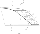
FIG. 1 is a front view of a side window encapsulation assembly according to an embodiment. -
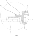
FIG. 2 is a sectional view taken along a line A-A inFIG. 1 . -
FIG. 3 is a partial enlarged view of a portion D inFIG. 2 . -
FIG. 4 is a partial enlarged view of a portion E inFIG. 2 . -
FIG. 5 is a sectional view taken along a line B-B inFIG. 1 . -
FIG. 6 is a sectional view taken along a line C-C inFIG. 1 . -
FIG. 7 is a rear view of a side window encapsulation assembly according to an embodiment. -
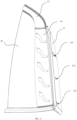
FIG. 8 is a front view of an encapsulation frame according to an embodiment. -
FIG. 9 is a schematic structural diagram of a light group assembly according to an embodiment. -
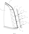
FIG. 10 is an exploded view of a side window encapsulation according to an embodiment. -
FIG. 11 is a partial enlarged view of a portion where a light group assembly and a decorative member in the side window encapsulation assembly according to the embodiment. -
FIG. 12 is an exploded view of the structure shown inFIG. 11 . - 10. side window encapsulation; 11. light group assembly; 111. insertion fitting part; 112. fastening member; 113. second connecting through hole; 12. encapsulation frame; 121. mounting opening; 122. mounting groove; 1221. first sidewall; 1222. second sidewall; 123. insertion part; 124. engaging part hole; 125. first connecting through hole; 126. connecting groove; 13. decorative member; 131. third connecting through hole; 14. bright strip; 15. first connecting member; 16. second connecting member; 17. flexible plastic material; 20. side window encapsulation assembly; 21. glass; 30. side enclosing sheet metal; 40. drainage channel sheet metal.
- In order to make the objects, features, and advantages of the present application more apparent and understandable, the specific implementations of the present application will be illustrated in detail below in conjunction with the accompanying drawings. In the following description, numerous specific details are set forth in order to facilitate a thorough understanding of the present application. However, the present application can be implemented in many other ways different from those described herein, and those skilled in the art can make similar modifications without departing from the spirit of the present application, so that the present application is not limited to the specific embodiments disclosed below.
- As shown in
FIGS. 1 ,2 ,8 and10 , in an embodiment, aside window encapsulation 10 is provided, which includes: - a
light group assembly 11; and - an
encapsulation frame 12 enclosing a mountingopening 121 configured for receiving aglass 21. As shown inFIG. 8 , a side surface of theencapsulation frame 12 facing away from an interior of a vehicle is an outer side surface, and a mountinggroove 122 is disposed on the outer side surface of theencapsulation frame 12. As shown inFIGS. 1 ,2 and10 , thelight group assembly 11 is removably mounted in the mountinggroove 122. Aninsertion part 123 and anengaging part 124 are respectively provided on two opposite sidewalls of the mountinggroove 122. - As shown in
FIGS. 2 to 4 andFIG. 9 , an insertionfitting part 111 is provided on thelight group assembly 11 at a position corresponding to theinsertion part 123. One of the insertionfitting part 111 and theinsertion part 123 is removably inserted into the other one. - A
fastening member 112 is disposed on a portion of thelight group assembly 11 corresponding to theengaging part 124. Thefastening member 112 and theengaging part 124 are removably engaged with each other. - According to the
side window encapsulation 10 according to the above embodiment, theinsertion part 123 and theengaging part 124 are respectively provided on the two opposite sidewalls of the mountinggroove 122, so that thelight group assembly 11 can be removably mounted in the mountinggroove 122. When thelight group assembly 11 needs to be replaced or maintained, thelight group assembly 11 can be removed from theencapsulation frame 12, thereby improving the convenience of operation and reducing the maintenance cost. In the assembling process, the insertionfitting part 111 and theinsertion part 123 are firstly coupled to each other, and then thelight group assembly 11 is pressed into the mountinggroove 122 until thefastening member 112 and theengaging part 124 are engaged with each other. When it is necessary to disassemble, thefastening member 112 and theengaging part 124 are detached from each other firstly, and then thelight group assembly 11 is removed from the mountinggroove 122. - In an embodiment, as shown in
FIGS. 2 and3 , theinsertion part 123 includes an inserting hole disposed on a sidewall of the mountinggroove 122. The insertionfitting part 111 includes a positioning protrusion disposed on thelight group assembly 11. The positioning protrusion can be removably inserted into the inserting hole. - Alternatively, in another embodiment, the
insertion part 123 can include a convex structure disposed on a sidewall of the mountinggroove 122. The insertionfitting part 111 includes a concave structure disposed on thelight group assembly 11. The convex structure can be removably inserted into the concave structure. - Further, in an embodiment, as shown in
FIGS. 2 and4 , theengaging part 124 includes an engaging hole disposed on a sidewall of the mountinggroove 122. Thefastening member 112 can be removably engaged in the engaging hole. - Further, in an embodiment, as shown in
FIG. 8 , the sidewall of the mountinggroove 122 provided with theinsertion part 123 is afirst sidewall 1221. The sidewall of the mountinggroove 122 provided with theengaging part 124 is asecond sidewall 1222. Thefirst sidewall 1221 and thesecond sidewall 1222 are arranged sequentially in a direction away from the mountingopening 121. Thesecond sidewall 1222 is located at an outer rim of theencapsulation frame 12. As shown inFIGS. 2 and4 , the engaging hole is formed on thesecond sidewall 1222. The engaging hole extends through theencapsulation frame 12 in the direction away from the mountingopening 121. - Thus, as shown in
FIGS. 2 and4 , when thelight group assembly 11 is mounted in the mountinggroove 122, thefastening member 112 can be pushed from an outside of theencapsulation frame 12, so as to remove thelight group assembly 11 from theencapsulation frame 12. As shown inFIGS. 2 to 4 , during mounting, thefastening member 112 is pressed into the engaging hole by means of an elastic deformation ability of thefastening member 112 itself, so that thefastening member 112 is hooked in the engaging hole. When thelight group assembly 11 needs to be replaced, thefastening member 112 hooked in the engaging hole is pushed from the outside of theencapsulation frame 12, so that thefastening member 112 can be separated from the engaging hole, and accordingly, thelight group assembly 11 can be removed. - Further, as shown in
FIGS. 1 and8 , when theside window encapsulation 10 is applied to a vehicle, a front side of the mountingopening 121 is a side where the vehicle head is located. The mountinggroove 122 is located at a rear side of the mountingopening 121. - The
second sidewall 1222 is located at a rear side rim of theencapsulation frame 12. As shown inFIGS. 2 to 4 , the engaging hole extends through a rear surface of theencapsulation frame 12. - As shown in
FIG. 2 , when theside window encapsulation 10 is applied to the vehicle, the engaging hole is exposed outside a side enclosingsheet metal 30 and a drainagechannel sheet metal 40 of the vehicle. Therefore, when replacing thelight group assembly 11, it is not necessary to remove theencapsulation frame 12 and theglass 21 from the vehicle, thereby further improving maintenance convenience. - Further, in an embodiment, as shown in
FIGS. 1 ,2 ,5 ,6 ,7 ,11 and12 , theside window encapsulation 10 further includes adecorative member 13. Thedecorative member 13 is disposed outside theencapsulation frame 12. Thedecorative member 13 shields a side of the engaging hole facing away from the mountingopening 121. Thedecorative member 13 has a shielding effect on the engaging hole, and improves the overall integrity of the appearance. - Further, when the
side window encapsulation 10 is applied to the vehicle, as shown inFIG. 2 , the drainagechannel sheet metal 40 is disposed on the rear side of the side enclosingsheet metal 30. Thedecorative member 13 abuts against the drainagechannel sheet metal 40 to shield theencapsulation frame 12. Moreover, the abutting between thedecorative member 13 and the drainagechannel sheet metal 40 also has a certain waterproof effect. - Further, in an embodiment, as shown in
FIG. 8 , a plurality ofinsertion parts 123 are disposed on thefirst sidewall 1221. The plurality ofinsertion parts 123 are sequentially arranged at intervals in a length direction of thefirst sidewall 1221. As shown inFIG. 9 , a plurality of insertionfitting parts 111 are provided on thelight group assembly 11. The plurality of insertionfitting parts 111 are arranged in one-to-one correspondence with theinsertion parts 123. - Further, as shown in
FIG. 8 , in an embodiment, a plurality of engaging holes are disposed on thesecond sidewall 1222. The plurality of engaging holes are sequentially arranged at intervals in a length direction of thesecond sidewall 1222. - As shown in
FIGS. 7 ,11 and12 , thedecorative member 13 is a strip plate. A length direction of thedecorative member 13 is parallel to the length direction of thesecond sidewall 1222. Thedecorative member 13 shields the side of each engaging hole facing away from the mountingopening 121. Under the shielding of thedecorative member 13, the engaging hole cannot be seen from the outside. When thelight group assembly 11 needs to be removed, thedecorative member 13 can be removed firstly, so as to expose the engaging hole before the subsequent disassembling process. - Further, a process of mounting the
glass 21 into the mountingopening 121 can include: firstly, placing theglass 21 and theencapsulation frame 12 into a molding die; and then injecting a flexible plastic material 17 between theglass 21 and theencapsulation frame 12 so that theglass 21 and theencapsulation frame 12 are formed into one piece. - As shown in
FIGS. 2 and3 , the flexible plastic material 17 is disposed at an outer rim of theglass 21. - Further, in an embodiment, as shown in
FIGS. 1 ,11 and12 , theside window encapsulation 10 further includes abright strip 14. Thebright strip 14 is disposed on a side of thelight group assembly 11 facing away from a bottom wall of the mountinggroove 122. As shown inFIGS. 2 ,3 ,7 ,11 and12 , one side of the two opposite sides of thebright strip 14 abuts against the flexible plastic material 17, another side of the two opposite sides of thebright strip 14 abuts against a long side of thedecorative member 13. Another long side of thedecorative member 13 is located on a side of theencapsulation frame 12 facing the interior of the vehicle. - Finally, as shown in
FIGS. 11 and12 , thelight group assembly 11 and the mountinggroove 122 are completely shielded by thebright strip 14 and thedecorative member 13. - The
bright strip 14 and thelight group assembly 11 may be adhered or engaged to each other, which is not specifically limited herein. - Further, as shown in
FIGS. 1 ,5 andFIGS. 8 to 10 , in an embodiment, a first connecting throughhole 125 is disposed on thesecond sidewall 1222, and a second connecting throughhole 113 is further disposed at a portion of thelight group assembly 11 corresponding to the first connecting throughhole 125. Theside window encapsulation 10 further includes a first connectingmember 15. The first connectingmember 15 extends through the first connecting throughhole 125 and the second connecting throughhole 113 to connect thelight group assembly 11 and theencapsulation frame 12. Thedecorative member 13 shields a side of the first connectingmember 15 facing away from the mountingopening 121. - The reliability of the connection between the
light group assembly 11 and theencapsulation frame 12 is further improved by the first connectingmember 15. Similarly, the first connectingmember 15 is also shielded by thedecorative member 13. - Further, as shown in
FIGS. 6 ,7 ,11 and12 , in an embodiment, theside window encapsulation 10 further includes a second connectingmember 16. A third connecting throughhole 131 is disposed on thedecorative member 13. A fourth connecting through hole (not shown in the figures) or a connectinggroove 126 is disposed at a portion of theencapsulation frame 12 corresponding to the third connecting throughhole 131. The second connectingmember 16 extends through the third connecting throughhole 131 and is inserted into the fourth connecting through hole or the connectinggroove 126, thereby connecting thedecorative member 13 and theencapsulation frame 12. - As shown in
FIG. 6 , when thedecorative member 13 is connected to theencapsulation frame 12 through the second connectingmember 16, one side edge of thebright strip 14 is pressed to a side adjacent to the mountingopening 121 by thedecorative member 13. - In some embodiments, the first connecting
member 15 can be a screw. Similarly, the second connectingmember 16 can also be a screw. Alternatively, in other embodiments, the first connectingmember 15 or the second connectingmember 16 can be other components capable of realizing connection, and which is not specifically limited herein. - Further, in still another embodiment, as shown in
FIGS. 1 and2 , there is provided a sidewindow encapsulation assembly 20 including aglass 21 and theside window encapsulation 10 as described above. Theglass 21 is mounted in the mountingopening 121. - The side
window encapsulation assembly 20 according to this embodiment adopts theside window encapsulation 10 described in any of the above embodiments, so as to improve the operation convenience during replacement and maintenance of thelight group assembly 11. In addition, theglass 21 can be kept intact in the maintenance process, thereby effectively reducing the maintenance cost. - In an embodiment, the
glass 21 is integrally connected to theencapsulation frame 12. - The
glass 21 and theencapsulation frame 12 can be placed in a molding die during processing, and then a flexible plastic material can be injected between theglass 21 and theencapsulation frame 12 so that theglass 21 and theencapsulation frame 12 are formed into one piece. The flexible plastic material can be thermoplastic elastomer (TPE), polyvinyl chloride (PVC), or polyurethane (PU). - Further, as shown in
FIGS. 2 and3 , in an embodiment, a portion of thepositioning protrusion 111 inserted into the insertinghole 123 is located on a side of theglass 21 facing the interior of the vehicle. Thepositioning protrusion 111 is pressed against an inner side of theencapsulation frame 12. - Further, in yet another embodiment, a vehicle is provided, which includes the above-described side
window encapsulation assembly 20. - The vehicle according to this embodiment adopts the side
window encapsulation assembly 20 described in any of the above embodiments, so as to effectively improve the operation convenience during replacement and maintenance of thelight group assembly 11 and reduce maintenance cost at the same time. - In the description of the present application, it is to be understood that orientations or positional relationships indicated by the terms "center", "longitudinal", "transverse", "length", "width", "thickness", "upper", "lower", "front", "rear", "left", "right", "vertical", "horizontal", "top", "bottom", "inner", "outer", "clockwise", "counterclockwise", "axial", "radial", "circumferential", etc. are based on the orientations or positional relationships shown in the drawings. These terms are only intended for facilitating illustrating the present application and simplifying the illustration, rather than indicating or implying that the devices or elements referred thereto have to present particular orientations, and be constructed and operated in particular orientations, and therefore cannot be construed as limiting the present application.
- In addition, the terms "first" and "second" are only intended for illustrative purposes, rather than being construed as indicating or implying relative importance or implicitly designating the number of the technical features as indicated. Thus, the features defined by "first" and "second" may explicitly or implicitly include at least one of the features. In the illustrations of the present application, the term "a plurality of" means at least two, for example two or three, unless otherwise explicitly and specifically defined.
- In the present application, unless otherwise expressly specified and defined, the terms "mounted", "connected to", "coupled" and "fixed" should be understood in a broad sense, for example, fixedly connected or removably connected, or integrated; mechanically connected or electrically connected; directly connected or indirectly connected through an intermediate medium, or in an interior communication or mutual interaction relationship between two elements, unless otherwise specifically defined. For those of ordinary skill in the art, the specific meanings of the above-described terms in the present application may be understood according to specific circumstances.
- In the present application, unless otherwise expressly stated and defined, a first feature, when being referred to as being located "above" or "below" a second feature, may be in direct contact with the second feature, or in indirect contact with the second feature via an intermediate feature. Moreover, a first feature, when being referred to as being disposed "on", "above" and "over" a second feature, may be disposed right above or obliquely above the second feature, or simply disposed at a level higher than the second feature. A first feature, when being referred to as being disposed "under", "below" and "beneath" a second feature, may be disposed directly below or obliquely below the second feature, or simply disposed at a level lower than the second feature.
- It should be noted that, when an element is referred to as being "fixed to" or "disposed on" another element, it may be directly on the other element or an intermediate element may also be present. When an element is referred to as being "connected" to another element, it may be directly connected to the other element or an intermediate element might be present at the same time. The terms "vertical", "horizontal", "up", "down", "left", "right" and similar expressions used herein are only for the purpose of illustration, rather than presenting the only ways for implementation.
- The technical features of the embodiments above may be combined arbitrarily. To make the description concise, not all possible combinations of the technical features in the above embodiments are described. However, as long as there are no contradictions in the combinations of these technical features, all the combinations should be considered to be within the scope of the specification.
- The embodiments above only represent several implementation modes of the present application, and the description thereof is relatively specific and detailed, but it should not be construed as limiting the scope of the patent. It should be noted that for those skilled in the art, various modifications and improvements may be made without departing from the concept of the present application, and all these modifications and improvements falls within the protection scope of the present application. Therefore, the scope of protection of the patent application should be subject to the appended claims.
Claims (14)
- A side window encapsulation, comprising:a light group assembly; andan encapsulation frame, wherein the encapsulation frame encloses a mounting opening configured for receiving a glass; a side surface of the encapsulation frame facing away from an interior of a vehicle is an outer side surface; a mounting groove is disposed on the outer side surface of the encapsulation frame; the light group assembly is removably mounted in the mounting groove; and an insertion part and an engaging part are respectively disposed on two opposite sidewalls of the mounting groove;wherein an insertion fitting part is disposed at a portion of the light group assembly corresponding to the insertion part, and one of the insertion fitting part and the insertion part is removably inserted in another one of the insertion fitting part and the insertion part; andwherein a fastening member is disposed at a portion of the light group assembly corresponding to the engaging part; and the fastening member is removably engaged with the engaging part.
- The side window encapsulation according to claim 1, wherein a sidewall of the mounting groove provided with the insertion part is a first sidewall, a sidewall of the mounting groove provided with the engaging part is a second sidewall; the first sidewall and the second sidewall are arranged sequentially in a direction away from the mounting opening; the second sidewall is located at an outer rim of the encapsulation frame; the engaging part comprises an engaging hole disposed on the second sidewall; the fastening member is removably engaged in the engaging hole; and the engaging hole extends through the encapsulation frame in the direction away from the mounting opening.
- The side window encapsulation according to claim 2, wherein the side window encapsulation further comprises a decorative member, wherein the decorative member is disposed outside the encapsulation frame; and the decorative member shields a side of the engaging hole facing away from the mounting opening.
- The side window encapsulation according to claim 3, wherein a plurality of insertion parts are disposed on the first sidewall; and the plurality of insertion parts are arranged at intervals in a length direction of the first sidewall; and
wherein a plurality of engaging holes are disposed on the second sidewall; the plurality of engaging holes are arranged at intervals in a length direction of the second sidewall; the decorative member is a strip plate; a length direction of the decorative member is parallel to the length direction of the second sidewall; and the decorative member shields a side of each of the engaging holes facing away from the mounting opening. - The side window encapsulation according to claim 4, wherein the encapsulation frame is capable of being integrally connected with the glass by an injection of a flexible plastic material; the side window encapsulation further comprises a bright strip disposed on a side of the light group assembly facing away from a bottom wall of the mounting groove; one side edge of two opposite side edges of the bright strip abuts against the flexible plastic material, another side edge of the two opposite side edges of the bright strip abuts against a long edge of the decorative member, and another long edge of the decorative member is located on a side of the encapsulation frame facing the interior of the vehicle.
- The side window encapsulation according to claim 5, wherein the bright strip is adhered or engaged to the light group assembly.
- The side window encapsulation according to claim 3, wherein a first connecting through hole is disposed on the second sidewall; a second connecting through hole is formed at a portion of the light group assembly corresponding to the first connecting through hole; the side window encapsulation further comprises a first connecting member, and wherein the first connecting member extends through the first connecting through hole and the second connecting through hole to connect the light group assembly and the encapsulation frame; and the decorative member shields a side of the first connecting member facing away from the mounting opening.
- The side window encapsulation according to claim 3, further comprising: a second connecting member, wherein a third connecting through hole is disposed on the decorative member; a fourth connecting through hole or a connecting groove is disposed at a portion of the encapsulation frame corresponding to the third connecting through hole; and the second connecting member extends through the third connecting through hole and is inserted into the fourth connecting through hole or the connecting groove to connect the decorative member and the encapsulation frame.
- The side window encapsulation according to any one of claims 1 to 7, wherein when applied to a vehicle, a front side of the mounting opening is a side where a vehicle head is located; and the mounting groove is located at a rear side of the mounting opening.
- A side window encapsulation assembly, comprising:a glass; andthe side window encapsulation according to any one of claims 1 to 9,wherein the glass is mounted in the mounting opening.
- The side window encapsulation assembly according to claim 10, wherein the glass is integrally connected with the encapsulation frame.
- The side window encapsulation assembly according to claim 10, wherein the insertion part comprises an inserting hole disposed on a sidewall of the mounting groove; the insertion fitting part comprises a positioning protrusion disposed on the light group assembly; wherein the positioning protrusion is removably inserted into the inserting hole; and a portion of the positioning protrusion inserted into the inserting hole is located on a side of the glass facing the interior of the vehicle.
- The side window encapsulation assembly according to claim 10, wherein the insertion part comprises a convex structure disposed on a sidewall of the mounting groove; the insertion fitting part comprises a concave structure disposed on the light group assembly; and the convex structure is removably inserted into the concave structure.
- A vehicle, comprising the side window encapsulation assembly according to any one of claims 10 to 13.
Applications Claiming Priority (2)
| Application Number | Priority Date | Filing Date | Title |
|---|---|---|---|
| CN202111106716.6A CN113696819B (en) | 2021-09-22 | 2021-09-22 | Side window edge covering mechanism, side window edge covering glass assembly and automobile |
| PCT/CN2022/120069 WO2023045938A1 (en) | 2021-09-22 | 2022-09-21 | Side window encapsulation mechanism, side window encapsulation glass assembly, and automobile |
Publications (3)
| Publication Number | Publication Date |
|---|---|
| EP4393775A1 true EP4393775A1 (en) | 2024-07-03 |
| EP4393775A4 EP4393775A4 (en) | 2024-11-13 |
| EP4393775B1 EP4393775B1 (en) | 2025-12-10 |
Family
ID=78661614
Family Applications (1)
| Application Number | Title | Priority Date | Filing Date |
|---|---|---|---|
| EP22871984.5A Active EP4393775B1 (en) | 2021-09-22 | 2022-09-21 | Side window encapsulation, side window encapsulation assembly, and vehicle |
Country Status (4)
| Country | Link |
|---|---|
| US (1) | US12447894B2 (en) |
| EP (1) | EP4393775B1 (en) |
| CN (1) | CN113696819B (en) |
| WO (1) | WO2023045938A1 (en) |
Families Citing this family (8)
| Publication number | Priority date | Publication date | Assignee | Title |
|---|---|---|---|---|
| CN113696819B (en) * | 2021-09-22 | 2022-11-01 | 福耀玻璃工业集团股份有限公司 | Side window edge covering mechanism, side window edge covering glass assembly and automobile |
| KR20240012641A (en) * | 2022-07-20 | 2024-01-30 | 현대자동차주식회사 | Quarter glass assembly for vehicle and manufacturing method for thereof |
| CN116001532B (en) * | 2023-01-04 | 2026-08-11 | 福耀玻璃工业集团股份有限公司 | Fixed window and vehicle |
| CN116118439B (en) * | 2023-02-09 | 2026-05-12 | 福耀玻璃工业集团股份有限公司 | Vehicle window assembly and vehicle |
| USD1079587S1 (en) * | 2023-05-12 | 2025-06-17 | Atieva, Inc. | Reconfigurable and flush, side windows and pillars of automotive vehicle |
| US20250242762A1 (en) * | 2024-01-25 | 2025-07-31 | Honda Motor Co., Ltd. | Vehicle quarter glass structure |
| CN119037103B (en) * | 2024-09-13 | 2025-12-09 | 福耀玻璃工业集团股份有限公司 | Glass assembly and vehicle |
| CN120735557B (en) * | 2025-06-04 | 2026-07-10 | 福耀玻璃工业集团股份有限公司 | Glass assembly and vehicle |
Family Cites Families (19)
| Publication number | Priority date | Publication date | Assignee | Title |
|---|---|---|---|---|
| US5839231A (en) * | 1996-08-02 | 1998-11-24 | Excel Industries, Inc. | Window assembly with light |
| JP4199055B2 (en) * | 2003-06-10 | 2008-12-17 | 矢崎総業株式会社 | Lamp unit mounting structure |
| FR2978525B1 (en) * | 2011-07-29 | 2018-05-18 | Saint-Gobain Glass France | LUMINOUS MULTIPLE FURNITURE GLAZING |
| FR2995829B1 (en) * | 2012-09-25 | 2015-06-26 | Saint Gobain | GLAZING WITH PROFILE JOINT ENCAPSULE AND REPORTED PART FIXED TO THE SEAL, FASTENING ELEMENT OF THE REPORTED PART FOR THE GLAZING AND METHOD FOR PRODUCING THE GLAZING. |
| FR3012393B1 (en) * | 2013-10-31 | 2015-11-27 | Peugeot Citroen Automobiles Sa | OPTICAL BLOCK ARRANGEMENT ON HIGHER BAY OF VEHICLE WINDSHIELD AND CORRESPONDING VEHICLE |
| CN104149706A (en) * | 2014-07-28 | 2014-11-19 | 贵州贵龙客车制造有限公司 | Passenger car combined interior trim part air channel easy to remove and dismount and mounting method thereof |
| CN104354570A (en) | 2014-11-13 | 2015-02-18 | 福耀玻璃工业集团股份有限公司 | Window glass unit |
| US9896026B2 (en) * | 2015-01-13 | 2018-02-20 | Magna Mirrors Of America, Inc. | Slider window assembly with integrated lighting |
| GB201500883D0 (en) * | 2015-01-19 | 2015-03-04 | Pilkington Group Ltd | Vehicle glazing |
| US10618462B2 (en) * | 2016-11-01 | 2020-04-14 | Custom Glass Solutions, Llc | Encapsulation-embedded exterior-facing light set for vehicles, and/or method of making the same |
| CN207374068U (en) * | 2017-09-19 | 2018-05-18 | 华晨汽车集团控股有限公司 | A kind of automotive back window construction |
| CN209719405U (en) * | 2019-01-24 | 2019-12-03 | 福耀玻璃工业集团股份有限公司 | A kind of vehicle glass atmosphere lamp assembly |
| CN209795369U (en) * | 2019-04-02 | 2019-12-17 | 福耀玻璃工业集团股份有限公司 | A car corner window glass with a light emitting module |
| DE102019208465A1 (en) * | 2019-06-11 | 2020-12-17 | Volkswagen Aktiengesellschaft | Cover for at least one window of a motor vehicle |
| CN210912278U (en) * | 2019-10-30 | 2020-07-03 | 长城汽车股份有限公司 | Side window glass assembly with trim and vehicle with the same |
| CN111231855A (en) * | 2020-01-16 | 2020-06-05 | 桂林皮尔金顿安全玻璃有限公司 | Mounting structure for bright strip of rear triangular window of vehicle |
| CN111674339B (en) * | 2020-05-27 | 2025-05-27 | 宁波信泰机械有限公司 | External decorative strip with light |
| CN213920840U (en) * | 2020-11-13 | 2021-08-10 | 福耀玻璃工业集团股份有限公司 | Luminous glass assembly |
| CN113696819B (en) * | 2021-09-22 | 2022-11-01 | 福耀玻璃工业集团股份有限公司 | Side window edge covering mechanism, side window edge covering glass assembly and automobile |
-
2021
- 2021-09-22 CN CN202111106716.6A patent/CN113696819B/en active Active
-
2022
- 2022-09-21 EP EP22871984.5A patent/EP4393775B1/en active Active
- 2022-09-21 WO PCT/CN2022/120069 patent/WO2023045938A1/en not_active Ceased
- 2022-09-21 US US18/693,712 patent/US12447894B2/en active Active
Also Published As
| Publication number | Publication date |
|---|---|
| CN113696819B (en) | 2022-11-01 |
| EP4393775A4 (en) | 2024-11-13 |
| US20240375577A1 (en) | 2024-11-14 |
| EP4393775B1 (en) | 2025-12-10 |
| WO2023045938A1 (en) | 2023-03-30 |
| CN113696819A (en) | 2021-11-26 |
| US12447894B2 (en) | 2025-10-21 |
Similar Documents
| Publication | Publication Date | Title |
|---|---|---|
| US12447894B2 (en) | Side window encapsulation, side window encapsulation assembly, and vehicle | |
| US6352322B1 (en) | Portable liquid crystal display device | |
| US20130329345A1 (en) | Housing structure and electronic device using the same | |
| EP1209880A2 (en) | Housing for an electronic device | |
| EP3879380A1 (en) | Display apparatus | |
| CN106091526A (en) | A kind of refrigerator door display module and refrigerator | |
| EP4309934A1 (en) | Vehicle window assembly and vehicle | |
| US6116678A (en) | Limousine side structure and window sealing method | |
| CN108317624B (en) | Window type air conditioner panel assembly structure and window type air conditioner | |
| CN213642551U (en) | Infusion pump | |
| CN211187190U (en) | Monitor and shell assembly thereof | |
| CN210179347U (en) | Support lamp | |
| CN215770304U (en) | badge | |
| CN220455577U (en) | Lens cap assembly and thermal infrared imager | |
| CN211294492U (en) | Goods shelf advertisement machine | |
| CN210295801U (en) | Cambered surface marker light structure | |
| CN206031239U (en) | Door flush mounting plate of switch mounting structure and door | |
| CN218524997U (en) | Liquid crystal splicing screen for projection | |
| CN222465059U (en) | An electronic doorbell internal unit that is easy to assemble | |
| CN217816400U (en) | Multipurpose flat lamp | |
| CN215675053U (en) | Lamp holder structure for automobile lamp | |
| CN210606468U (en) | Sealing structure of backlight source and display screen | |
| CN212516983U (en) | General base of touch switch and touch switch with same | |
| CN217406952U (en) | Display control equipment | |
| CN220913646U (en) | Code scanning device |
Legal Events
| Date | Code | Title | Description |
|---|---|---|---|
| STAA | Information on the status of an ep patent application or granted ep patent |
Free format text: STATUS: THE INTERNATIONAL PUBLICATION HAS BEEN MADE |
|
| PUAI | Public reference made under article 153(3) epc to a published international application that has entered the european phase |
Free format text: ORIGINAL CODE: 0009012 |
|
| STAA | Information on the status of an ep patent application or granted ep patent |
Free format text: STATUS: REQUEST FOR EXAMINATION WAS MADE |
|
| 17P | Request for examination filed |
Effective date: 20240326 |
|
| AK | Designated contracting states |
Kind code of ref document: A1 Designated state(s): AL AT BE BG CH CY CZ DE DK EE ES FI FR GB GR HR HU IE IS IT LI LT LU LV MC MK MT NL NO PL PT RO RS SE SI SK SM TR |
|
| A4 | Supplementary search report drawn up and despatched |
Effective date: 20241011 |
|
| RIC1 | Information provided on ipc code assigned before grant |
Ipc: B60Q 1/32 20060101ALN20241008BHEP Ipc: B60Q 1/26 20060101ALI20241008BHEP Ipc: B60R 13/04 20060101ALI20241008BHEP Ipc: B60J 1/20 20060101ALI20241008BHEP Ipc: B60J 1/08 20060101ALI20241008BHEP Ipc: B60Q 3/208 20170101AFI20241008BHEP |
|
| DAV | Request for validation of the european patent (deleted) | ||
| DAX | Request for extension of the european patent (deleted) | ||
| GRAP | Despatch of communication of intention to grant a patent |
Free format text: ORIGINAL CODE: EPIDOSNIGR1 |
|
| STAA | Information on the status of an ep patent application or granted ep patent |
Free format text: STATUS: GRANT OF PATENT IS INTENDED |
|
| RIC1 | Information provided on ipc code assigned before grant |
Ipc: B60Q 1/32 20060101ALN20250530BHEP Ipc: B60J 10/70 20160101ALI20250530BHEP Ipc: B60J 1/10 20060101ALI20250530BHEP Ipc: B60Q 1/26 20060101ALI20250530BHEP Ipc: B60R 13/04 20060101ALI20250530BHEP Ipc: B60J 1/20 20060101ALI20250530BHEP Ipc: B60J 1/08 20060101ALI20250530BHEP Ipc: B60Q 3/208 20170101AFI20250530BHEP |
|
| RIC1 | Information provided on ipc code assigned before grant |
Ipc: B60Q 3/208 20170101AFI20250616BHEP Ipc: B60J 1/08 20060101ALI20250616BHEP Ipc: B60J 1/20 20060101ALI20250616BHEP Ipc: B60R 13/04 20060101ALI20250616BHEP Ipc: B60Q 1/26 20060101ALI20250616BHEP Ipc: B60J 1/10 20060101ALI20250616BHEP Ipc: B60J 10/70 20160101ALI20250616BHEP Ipc: B60Q 1/32 20060101ALN20250616BHEP |
|
| INTG | Intention to grant announced |
Effective date: 20250708 |
|
| GRAS | Grant fee paid |
Free format text: ORIGINAL CODE: EPIDOSNIGR3 |
|
| GRAA | (expected) grant |
Free format text: ORIGINAL CODE: 0009210 |
|
| STAA | Information on the status of an ep patent application or granted ep patent |
Free format text: STATUS: THE PATENT HAS BEEN GRANTED |
|
| AK | Designated contracting states |
Kind code of ref document: B1 Designated state(s): AL AT BE BG CH CY CZ DE DK EE ES FI FR GB GR HR HU IE IS IT LI LT LU LV MC MK MT NL NO PL PT RO RS SE SI SK SM TR |
|
| REG | Reference to a national code |
Ref country code: CH Ref legal event code: F10 Free format text: ST27 STATUS EVENT CODE: U-0-0-F10-F00 (AS PROVIDED BY THE NATIONAL OFFICE) Effective date: 20251210 Ref country code: GB Ref legal event code: FG4D |
|
| P01 | Opt-out of the competence of the unified patent court (upc) registered |
Free format text: CASE NUMBER: UPC_APP_0012434_4393775/2025 Effective date: 20251106 |
|
| REG | Reference to a national code |
Ref country code: DE Ref legal event code: R096 Ref document number: 602022026791 Country of ref document: DE Ref country code: IE Ref legal event code: FG4D |
|
| PG25 | Lapsed in a contracting state [announced via postgrant information from national office to epo] |
Ref country code: ES Free format text: LAPSE BECAUSE OF FAILURE TO SUBMIT A TRANSLATION OF THE DESCRIPTION OR TO PAY THE FEE WITHIN THE PRESCRIBED TIME-LIMIT Effective date: 20251210 |
|
| REG | Reference to a national code |
Ref country code: LT Ref legal event code: MG9D |
|
| PG25 | Lapsed in a contracting state [announced via postgrant information from national office to epo] |
Ref country code: NO Free format text: LAPSE BECAUSE OF FAILURE TO SUBMIT A TRANSLATION OF THE DESCRIPTION OR TO PAY THE FEE WITHIN THE PRESCRIBED TIME-LIMIT Effective date: 20260310 |
|
| PG25 | Lapsed in a contracting state [announced via postgrant information from national office to epo] |
Ref country code: FI Free format text: LAPSE BECAUSE OF FAILURE TO SUBMIT A TRANSLATION OF THE DESCRIPTION OR TO PAY THE FEE WITHIN THE PRESCRIBED TIME-LIMIT Effective date: 20251210 Ref country code: HR Free format text: LAPSE BECAUSE OF FAILURE TO SUBMIT A TRANSLATION OF THE DESCRIPTION OR TO PAY THE FEE WITHIN THE PRESCRIBED TIME-LIMIT Effective date: 20251210 |
|
| REG | Reference to a national code |
Ref country code: NL Ref legal event code: MP Effective date: 20251210 |
|
| PG25 | Lapsed in a contracting state [announced via postgrant information from national office to epo] |
Ref country code: RS Free format text: LAPSE BECAUSE OF FAILURE TO SUBMIT A TRANSLATION OF THE DESCRIPTION OR TO PAY THE FEE WITHIN THE PRESCRIBED TIME-LIMIT Effective date: 20260310 |
|
| PG25 | Lapsed in a contracting state [announced via postgrant information from national office to epo] |
Ref country code: LV Free format text: LAPSE BECAUSE OF FAILURE TO SUBMIT A TRANSLATION OF THE DESCRIPTION OR TO PAY THE FEE WITHIN THE PRESCRIBED TIME-LIMIT Effective date: 20251210 |
|
| PG25 | Lapsed in a contracting state [announced via postgrant information from national office to epo] |
Ref country code: BG Free format text: LAPSE BECAUSE OF FAILURE TO SUBMIT A TRANSLATION OF THE DESCRIPTION OR TO PAY THE FEE WITHIN THE PRESCRIBED TIME-LIMIT Effective date: 20251210 |
|
| REG | Reference to a national code |
Ref country code: AT Ref legal event code: MK05 Ref document number: 1865885 Country of ref document: AT Kind code of ref document: T Effective date: 20251210 |
|
| PG25 | Lapsed in a contracting state [announced via postgrant information from national office to epo] |
Ref country code: NL Free format text: LAPSE BECAUSE OF FAILURE TO SUBMIT A TRANSLATION OF THE DESCRIPTION OR TO PAY THE FEE WITHIN THE PRESCRIBED TIME-LIMIT Effective date: 20251210 |
|
| PG25 | Lapsed in a contracting state [announced via postgrant information from national office to epo] |
Ref country code: LT Free format text: LAPSE BECAUSE OF FAILURE TO SUBMIT A TRANSLATION OF THE DESCRIPTION OR TO PAY THE FEE WITHIN THE PRESCRIBED TIME-LIMIT Effective date: 20251210 |
|
| PG25 | Lapsed in a contracting state [announced via postgrant information from national office to epo] |
Ref country code: SM Free format text: LAPSE BECAUSE OF FAILURE TO SUBMIT A TRANSLATION OF THE DESCRIPTION OR TO PAY THE FEE WITHIN THE PRESCRIBED TIME-LIMIT Effective date: 20251210 |
|
| PG25 | Lapsed in a contracting state [announced via postgrant information from national office to epo] |
Ref country code: PL Free format text: LAPSE BECAUSE OF FAILURE TO SUBMIT A TRANSLATION OF THE DESCRIPTION OR TO PAY THE FEE WITHIN THE PRESCRIBED TIME-LIMIT Effective date: 20251210 |
|
| PG25 | Lapsed in a contracting state [announced via postgrant information from national office to epo] |
Ref country code: IT Free format text: LAPSE BECAUSE OF FAILURE TO SUBMIT A TRANSLATION OF THE DESCRIPTION OR TO PAY THE FEE WITHIN THE PRESCRIBED TIME-LIMIT Effective date: 20251210 |
|
| PG25 | Lapsed in a contracting state [announced via postgrant information from national office to epo] |
Ref country code: AT Free format text: LAPSE BECAUSE OF FAILURE TO SUBMIT A TRANSLATION OF THE DESCRIPTION OR TO PAY THE FEE WITHIN THE PRESCRIBED TIME-LIMIT Effective date: 20251210 |
|
| PG25 | Lapsed in a contracting state [announced via postgrant information from national office to epo] |
Ref country code: EE Free format text: LAPSE BECAUSE OF FAILURE TO SUBMIT A TRANSLATION OF THE DESCRIPTION OR TO PAY THE FEE WITHIN THE PRESCRIBED TIME-LIMIT Effective date: 20251210 |
|
| PG25 | Lapsed in a contracting state [announced via postgrant information from national office to epo] |
Ref country code: IS Free format text: LAPSE BECAUSE OF FAILURE TO SUBMIT A TRANSLATION OF THE DESCRIPTION OR TO PAY THE FEE WITHIN THE PRESCRIBED TIME-LIMIT Effective date: 20260410 Ref country code: PT Free format text: LAPSE BECAUSE OF FAILURE TO SUBMIT A TRANSLATION OF THE DESCRIPTION OR TO PAY THE FEE WITHIN THE PRESCRIBED TIME-LIMIT Effective date: 20260410 |
|
| PG25 | Lapsed in a contracting state [announced via postgrant information from national office to epo] |
Ref country code: CZ Free format text: LAPSE BECAUSE OF FAILURE TO SUBMIT A TRANSLATION OF THE DESCRIPTION OR TO PAY THE FEE WITHIN THE PRESCRIBED TIME-LIMIT Effective date: 20251210 |
|
| PG25 | Lapsed in a contracting state [announced via postgrant information from national office to epo] |
Ref country code: SK Free format text: LAPSE BECAUSE OF FAILURE TO SUBMIT A TRANSLATION OF THE DESCRIPTION OR TO PAY THE FEE WITHIN THE PRESCRIBED TIME-LIMIT Effective date: 20251210 |
|
| PG25 | Lapsed in a contracting state [announced via postgrant information from national office to epo] |
Ref country code: SE Free format text: LAPSE BECAUSE OF FAILURE TO SUBMIT A TRANSLATION OF THE DESCRIPTION OR TO PAY THE FEE WITHIN THE PRESCRIBED TIME-LIMIT Effective date: 20251210 |