EP4393763A1 - Rapid charge/discharge system - Google Patents
Rapid charge/discharge system Download PDFInfo
- Publication number
- EP4393763A1 EP4393763A1 EP23206325.5A EP23206325A EP4393763A1 EP 4393763 A1 EP4393763 A1 EP 4393763A1 EP 23206325 A EP23206325 A EP 23206325A EP 4393763 A1 EP4393763 A1 EP 4393763A1
- Authority
- EP
- European Patent Office
- Prior art keywords
- control unit
- inverter
- discharge system
- rapid charge
- load
- Prior art date
- Legal status (The legal status is an assumption and is not a legal conclusion. Google has not performed a legal analysis and makes no representation as to the accuracy of the status listed.)
- Granted
Links
Images


Classifications
-
- H—ELECTRICITY
- H02—GENERATION; CONVERSION OR DISTRIBUTION OF ELECTRIC POWER
- H02P—CONTROL OR REGULATION OF ELECTRIC MOTORS, ELECTRIC GENERATORS OR DYNAMO-ELECTRIC CONVERTERS; CONTROLLING TRANSFORMERS, REACTORS OR CHOKE COILS
- H02P27/00—Arrangements or methods for the control of AC motors characterised by the kind of supply voltage
- H02P27/04—Arrangements or methods for the control of AC motors characterised by the kind of supply voltage using variable-frequency supply voltage, e.g. inverter or converter supply voltage
- H02P27/06—Arrangements or methods for the control of AC motors characterised by the kind of supply voltage using variable-frequency supply voltage, e.g. inverter or converter supply voltage using DC to AC converters or inverters
-
- B—PERFORMING OPERATIONS; TRANSPORTING
- B60—VEHICLES IN GENERAL
- B60L—PROPULSION OF ELECTRICALLY-PROPELLED VEHICLES; SUPPLYING ELECTRIC POWER FOR AUXILIARY EQUIPMENT OF ELECTRICALLY-PROPELLED VEHICLES; ELECTRODYNAMIC BRAKE SYSTEMS FOR VEHICLES IN GENERAL; MAGNETIC SUSPENSION OR LEVITATION FOR VEHICLES; MONITORING OPERATING VARIABLES OF ELECTRICALLY-PROPELLED VEHICLES; ELECTRIC SAFETY DEVICES FOR ELECTRICALLY-PROPELLED VEHICLES
- B60L53/00—Methods of charging batteries, specially adapted for electric vehicles; Charging stations or on-board charging equipment therefor; Exchange of energy storage elements in electric vehicles
- B60L53/10—Methods of charging batteries, specially adapted for electric vehicles; Charging stations or on-board charging equipment therefor; Exchange of energy storage elements in electric vehicles characterised by the energy transfer between the charging station and the vehicle
- B60L53/11—DC charging controlled by the charging station, e.g. mode 4
-
- B—PERFORMING OPERATIONS; TRANSPORTING
- B60—VEHICLES IN GENERAL
- B60L—PROPULSION OF ELECTRICALLY-PROPELLED VEHICLES; SUPPLYING ELECTRIC POWER FOR AUXILIARY EQUIPMENT OF ELECTRICALLY-PROPELLED VEHICLES; ELECTRODYNAMIC BRAKE SYSTEMS FOR VEHICLES IN GENERAL; MAGNETIC SUSPENSION OR LEVITATION FOR VEHICLES; MONITORING OPERATING VARIABLES OF ELECTRICALLY-PROPELLED VEHICLES; ELECTRIC SAFETY DEVICES FOR ELECTRICALLY-PROPELLED VEHICLES
- B60L1/00—Supplying electric power to auxiliary equipment of vehicles
- B60L1/006—Supplying electric power to auxiliary equipment of vehicles to power outlets
-
- B—PERFORMING OPERATIONS; TRANSPORTING
- B60—VEHICLES IN GENERAL
- B60L—PROPULSION OF ELECTRICALLY-PROPELLED VEHICLES; SUPPLYING ELECTRIC POWER FOR AUXILIARY EQUIPMENT OF ELECTRICALLY-PROPELLED VEHICLES; ELECTRODYNAMIC BRAKE SYSTEMS FOR VEHICLES IN GENERAL; MAGNETIC SUSPENSION OR LEVITATION FOR VEHICLES; MONITORING OPERATING VARIABLES OF ELECTRICALLY-PROPELLED VEHICLES; ELECTRIC SAFETY DEVICES FOR ELECTRICALLY-PROPELLED VEHICLES
- B60L50/00—Electric propulsion with power supplied within the vehicle
- B60L50/50—Electric propulsion with power supplied within the vehicle using propulsion power supplied by batteries or fuel cells
- B60L50/51—Electric propulsion with power supplied within the vehicle using propulsion power supplied by batteries or fuel cells characterised by AC-motors
-
- B—PERFORMING OPERATIONS; TRANSPORTING
- B60—VEHICLES IN GENERAL
- B60L—PROPULSION OF ELECTRICALLY-PROPELLED VEHICLES; SUPPLYING ELECTRIC POWER FOR AUXILIARY EQUIPMENT OF ELECTRICALLY-PROPELLED VEHICLES; ELECTRODYNAMIC BRAKE SYSTEMS FOR VEHICLES IN GENERAL; MAGNETIC SUSPENSION OR LEVITATION FOR VEHICLES; MONITORING OPERATING VARIABLES OF ELECTRICALLY-PROPELLED VEHICLES; ELECTRIC SAFETY DEVICES FOR ELECTRICALLY-PROPELLED VEHICLES
- B60L53/00—Methods of charging batteries, specially adapted for electric vehicles; Charging stations or on-board charging equipment therefor; Exchange of energy storage elements in electric vehicles
- B60L53/20—Methods of charging batteries, specially adapted for electric vehicles; Charging stations or on-board charging equipment therefor; Exchange of energy storage elements in electric vehicles characterised by converters located in the vehicle
- B60L53/24—Using the vehicle's propulsion converter for charging
-
- B—PERFORMING OPERATIONS; TRANSPORTING
- B60—VEHICLES IN GENERAL
- B60L—PROPULSION OF ELECTRICALLY-PROPELLED VEHICLES; SUPPLYING ELECTRIC POWER FOR AUXILIARY EQUIPMENT OF ELECTRICALLY-PROPELLED VEHICLES; ELECTRODYNAMIC BRAKE SYSTEMS FOR VEHICLES IN GENERAL; MAGNETIC SUSPENSION OR LEVITATION FOR VEHICLES; MONITORING OPERATING VARIABLES OF ELECTRICALLY-PROPELLED VEHICLES; ELECTRIC SAFETY DEVICES FOR ELECTRICALLY-PROPELLED VEHICLES
- B60L53/00—Methods of charging batteries, specially adapted for electric vehicles; Charging stations or on-board charging equipment therefor; Exchange of energy storage elements in electric vehicles
- B60L53/30—Constructional details of charging stations
- B60L53/31—Charging columns specially adapted for electric vehicles
-
- B—PERFORMING OPERATIONS; TRANSPORTING
- B60—VEHICLES IN GENERAL
- B60L—PROPULSION OF ELECTRICALLY-PROPELLED VEHICLES; SUPPLYING ELECTRIC POWER FOR AUXILIARY EQUIPMENT OF ELECTRICALLY-PROPELLED VEHICLES; ELECTRODYNAMIC BRAKE SYSTEMS FOR VEHICLES IN GENERAL; MAGNETIC SUSPENSION OR LEVITATION FOR VEHICLES; MONITORING OPERATING VARIABLES OF ELECTRICALLY-PROPELLED VEHICLES; ELECTRIC SAFETY DEVICES FOR ELECTRICALLY-PROPELLED VEHICLES
- B60L53/00—Methods of charging batteries, specially adapted for electric vehicles; Charging stations or on-board charging equipment therefor; Exchange of energy storage elements in electric vehicles
- B60L53/60—Monitoring or controlling charging stations
- B60L53/62—Monitoring or controlling charging stations in response to charging parameters, e.g. current, voltage or electrical charge
-
- B—PERFORMING OPERATIONS; TRANSPORTING
- B60—VEHICLES IN GENERAL
- B60L—PROPULSION OF ELECTRICALLY-PROPELLED VEHICLES; SUPPLYING ELECTRIC POWER FOR AUXILIARY EQUIPMENT OF ELECTRICALLY-PROPELLED VEHICLES; ELECTRODYNAMIC BRAKE SYSTEMS FOR VEHICLES IN GENERAL; MAGNETIC SUSPENSION OR LEVITATION FOR VEHICLES; MONITORING OPERATING VARIABLES OF ELECTRICALLY-PROPELLED VEHICLES; ELECTRIC SAFETY DEVICES FOR ELECTRICALLY-PROPELLED VEHICLES
- B60L55/00—Arrangements for supplying energy stored within a vehicle to a power network, i.e. vehicle-to-grid [V2G] arrangements
-
- H—ELECTRICITY
- H02—GENERATION; CONVERSION OR DISTRIBUTION OF ELECTRIC POWER
- H02H—EMERGENCY PROTECTIVE CIRCUIT ARRANGEMENTS
- H02H7/00—Emergency protective circuit arrangements specially adapted for specific types of electric machines or apparatus or for sectionalised protection of cable or line systems, and effecting automatic switching in the event of an undesired change from normal working conditions
- H02H7/08—Emergency protective circuit arrangements specially adapted for specific types of electric machines or apparatus or for sectionalised protection of cable or line systems, and effecting automatic switching in the event of an undesired change from normal working conditions for dynamo-electric motors
- H02H7/085—Emergency protective circuit arrangements specially adapted for specific types of electric machines or apparatus or for sectionalised protection of cable or line systems, and effecting automatic switching in the event of an undesired change from normal working conditions for dynamo-electric motors against excessive load
-
- H—ELECTRICITY
- H02—GENERATION; CONVERSION OR DISTRIBUTION OF ELECTRIC POWER
- H02J—ELECTRIC POWER NETWORKS; CIRCUIT ARRANGEMENTS OR SYSTEMS FOR SUPPLYING OR DISTRIBUTING ELECTRIC POWER; SYSTEMS FOR STORING ELECTRIC ENERGY
- H02J7/00—Circuit arrangements for charging or discharging batteries or for supplying loads from batteries
- H02J7/865—Battery or charger load switching, e.g. concurrent charging and load supply
-
- H—ELECTRICITY
- H02—GENERATION; CONVERSION OR DISTRIBUTION OF ELECTRIC POWER
- H02J—ELECTRIC POWER NETWORKS; CIRCUIT ARRANGEMENTS OR SYSTEMS FOR SUPPLYING OR DISTRIBUTING ELECTRIC POWER; SYSTEMS FOR STORING ELECTRIC ENERGY
- H02J7/00—Circuit arrangements for charging or discharging batteries or for supplying loads from batteries
- H02J7/90—Regulation of charging or discharging current or voltage
- H02J7/94—Regulation of charging or discharging current or voltage in response to battery current
-
- H—ELECTRICITY
- H02—GENERATION; CONVERSION OR DISTRIBUTION OF ELECTRIC POWER
- H02J—ELECTRIC POWER NETWORKS; CIRCUIT ARRANGEMENTS OR SYSTEMS FOR SUPPLYING OR DISTRIBUTING ELECTRIC POWER; SYSTEMS FOR STORING ELECTRIC ENERGY
- H02J7/00—Circuit arrangements for charging or discharging batteries or for supplying loads from batteries
- H02J7/90—Regulation of charging or discharging current or voltage
- H02J7/96—Regulation of charging or discharging current or voltage in response to battery voltage
-
- H—ELECTRICITY
- H02—GENERATION; CONVERSION OR DISTRIBUTION OF ELECTRIC POWER
- H02P—CONTROL OR REGULATION OF ELECTRIC MOTORS, ELECTRIC GENERATORS OR DYNAMO-ELECTRIC CONVERTERS; CONTROLLING TRANSFORMERS, REACTORS OR CHOKE COILS
- H02P27/00—Arrangements or methods for the control of AC motors characterised by the kind of supply voltage
- H02P27/04—Arrangements or methods for the control of AC motors characterised by the kind of supply voltage using variable-frequency supply voltage, e.g. inverter or converter supply voltage
- H02P27/06—Arrangements or methods for the control of AC motors characterised by the kind of supply voltage using variable-frequency supply voltage, e.g. inverter or converter supply voltage using DC to AC converters or inverters
- H02P27/08—Arrangements or methods for the control of AC motors characterised by the kind of supply voltage using variable-frequency supply voltage, e.g. inverter or converter supply voltage using DC to AC converters or inverters with pulse width modulation
- H02P27/085—Arrangements or methods for the control of AC motors characterised by the kind of supply voltage using variable-frequency supply voltage, e.g. inverter or converter supply voltage using DC to AC converters or inverters with pulse width modulation wherein the PWM mode is adapted on the running conditions of the motor, e.g. the switching frequency
-
- B—PERFORMING OPERATIONS; TRANSPORTING
- B60—VEHICLES IN GENERAL
- B60L—PROPULSION OF ELECTRICALLY-PROPELLED VEHICLES; SUPPLYING ELECTRIC POWER FOR AUXILIARY EQUIPMENT OF ELECTRICALLY-PROPELLED VEHICLES; ELECTRODYNAMIC BRAKE SYSTEMS FOR VEHICLES IN GENERAL; MAGNETIC SUSPENSION OR LEVITATION FOR VEHICLES; MONITORING OPERATING VARIABLES OF ELECTRICALLY-PROPELLED VEHICLES; ELECTRIC SAFETY DEVICES FOR ELECTRICALLY-PROPELLED VEHICLES
- B60L2220/00—Electrical machine types; Structures or applications thereof
- B60L2220/50—Structural details of electrical machines
- B60L2220/58—Structural details of electrical machines with more than three phases
-
- B—PERFORMING OPERATIONS; TRANSPORTING
- B60—VEHICLES IN GENERAL
- B60Y—INDEXING SCHEME RELATING TO ASPECTS CROSS-CUTTING VEHICLE TECHNOLOGY
- B60Y2200/00—Type of vehicle
- B60Y2200/90—Vehicles comprising electric prime movers
- B60Y2200/91—Electric vehicles
-
- B—PERFORMING OPERATIONS; TRANSPORTING
- B60—VEHICLES IN GENERAL
- B60Y—INDEXING SCHEME RELATING TO ASPECTS CROSS-CUTTING VEHICLE TECHNOLOGY
- B60Y2400/00—Special features of vehicle units
- B60Y2400/30—Sensors
- B60Y2400/308—Electric sensors
- B60Y2400/3084—Electric currents sensors
-
- B—PERFORMING OPERATIONS; TRANSPORTING
- B60—VEHICLES IN GENERAL
- B60Y—INDEXING SCHEME RELATING TO ASPECTS CROSS-CUTTING VEHICLE TECHNOLOGY
- B60Y2400/00—Special features of vehicle units
- B60Y2400/30—Sensors
- B60Y2400/308—Electric sensors
- B60Y2400/3086—Electric voltages sensors
-
- H—ELECTRICITY
- H02—GENERATION; CONVERSION OR DISTRIBUTION OF ELECTRIC POWER
- H02J—ELECTRIC POWER NETWORKS; CIRCUIT ARRANGEMENTS OR SYSTEMS FOR SUPPLYING OR DISTRIBUTING ELECTRIC POWER; SYSTEMS FOR STORING ELECTRIC ENERGY
- H02J2207/00—Details of circuit arrangements for charging or discharging batteries or supplying loads from batteries
- H02J2207/20—Charging or discharging characterised by the power electronics converter
-
- Y—GENERAL TAGGING OF NEW TECHNOLOGICAL DEVELOPMENTS; GENERAL TAGGING OF CROSS-SECTIONAL TECHNOLOGIES SPANNING OVER SEVERAL SECTIONS OF THE IPC; TECHNICAL SUBJECTS COVERED BY FORMER USPC CROSS-REFERENCE ART COLLECTIONS [XRACs] AND DIGESTS
- Y02—TECHNOLOGIES OR APPLICATIONS FOR MITIGATION OR ADAPTATION AGAINST CLIMATE CHANGE
- Y02T—CLIMATE CHANGE MITIGATION TECHNOLOGIES RELATED TO TRANSPORTATION
- Y02T10/00—Road transport of goods or passengers
- Y02T10/60—Other road transportation technologies with climate change mitigation effect
- Y02T10/70—Energy storage systems for electromobility, e.g. batteries
-
- Y—GENERAL TAGGING OF NEW TECHNOLOGICAL DEVELOPMENTS; GENERAL TAGGING OF CROSS-SECTIONAL TECHNOLOGIES SPANNING OVER SEVERAL SECTIONS OF THE IPC; TECHNICAL SUBJECTS COVERED BY FORMER USPC CROSS-REFERENCE ART COLLECTIONS [XRACs] AND DIGESTS
- Y02—TECHNOLOGIES OR APPLICATIONS FOR MITIGATION OR ADAPTATION AGAINST CLIMATE CHANGE
- Y02T—CLIMATE CHANGE MITIGATION TECHNOLOGIES RELATED TO TRANSPORTATION
- Y02T10/00—Road transport of goods or passengers
- Y02T10/60—Other road transportation technologies with climate change mitigation effect
- Y02T10/7072—Electromobility specific charging systems or methods for batteries, ultracapacitors, supercapacitors or double-layer capacitors
-
- Y—GENERAL TAGGING OF NEW TECHNOLOGICAL DEVELOPMENTS; GENERAL TAGGING OF CROSS-SECTIONAL TECHNOLOGIES SPANNING OVER SEVERAL SECTIONS OF THE IPC; TECHNICAL SUBJECTS COVERED BY FORMER USPC CROSS-REFERENCE ART COLLECTIONS [XRACs] AND DIGESTS
- Y02—TECHNOLOGIES OR APPLICATIONS FOR MITIGATION OR ADAPTATION AGAINST CLIMATE CHANGE
- Y02T—CLIMATE CHANGE MITIGATION TECHNOLOGIES RELATED TO TRANSPORTATION
- Y02T10/00—Road transport of goods or passengers
- Y02T10/80—Technologies aiming to reduce greenhouse gasses emissions common to all road transportation technologies
- Y02T10/92—Energy efficient charging or discharging systems for batteries, ultracapacitors, supercapacitors or double-layer capacitors specially adapted for vehicles
Definitions
- the inductance of the winding of the motor is used as one of the two ways of rapid charge, it is required that a neutral point of the motor be exposed from the motor for charging, and there is a risk that, if an angle of a position sensor is not accurate when a current flows to the motor, the electric vehicle may move because a torque is momentarily applied to the motor. In addition, the current is continuously applied to the winding of the motor, resulting in a rise in temperature of the motor.
- a rapid charge/discharge system includes: an inverter connected to a battery and including first to third switch legs to operate to charge or discharge the battery; first to third inductors each having one end connected to a node between two switches included in a corresponding one of the first to third switch legs, and the other end connected to a corresponding one of three phases of a motor; first to third capacitors each having one end connected to the other end of a corresponding one of the first to third inductors, and the other end being grounded; first to third terminals each having one end connected to the other end of a corresponding one of the first to third inductors; a load connected to the first to third terminals; and a control unit controlling the switches included in the inverter to be in a charging mode or a discharging mode according to a type of the load.
- All of the other ends of the first to third terminals may be connected to the load, such that the three phases of the motor are shorted.
- the rapid charge/discharge system may further include a DC link capacitor connected to the battery in parallel.
- the control unit may control the inverter to be in the charging mode or the discharging mode after the initialization, and when a phase deviation of a three-phase current of the motor is greater than a reference value, the control unit may store a contact defect occurrence record, and control the relay to be turned off or stop the operation of the inverter.
- control unit may control the inverter to be in the charging mode or the discharging mode, and when an RPS value changes, the control unit may store a contact defect occurrence record, and control the relay to be turned off or stop the operation of the inverter.
- control unit may stop the operation of the inverter after discharging the first to third inductors and the first to third capacitors.
- control unit may store a discharge error occurrence record, and control the relay to be turned off or stop the operation of the inverter.
- the battery can be rapidly charged at a high voltage without adding any hardware other than the LC network.
Landscapes
- Engineering & Computer Science (AREA)
- Power Engineering (AREA)
- Transportation (AREA)
- Mechanical Engineering (AREA)
- Life Sciences & Earth Sciences (AREA)
- Sustainable Development (AREA)
- Sustainable Energy (AREA)
- Charge And Discharge Circuits For Batteries Or The Like (AREA)
Abstract
Description
- The following disclosure relates to a rapid charge/discharge system, and more particularly, to a rapid charge/discharge system applicable to a typical three-phase inverter and capable of performing rapid charge for step-up to a high voltage and performing a V2X function while expanding an operating range of a motor.
- As a way of rapidly charging an electric vehicle at a high voltage (800V), it has been proposed to apply a separate charger or use a winding inductance of a motor.
- Recently, electric vehicle manufacturers aiming for high-performance electric vehicles have developed and released high-voltage rapid charge systems. However, most of the rapid charge systems built as infrastructure are 400V systems. Therefore, separate step-up devices are required for charging and discharging at 800V. As a way of providing such a separate step-up device, an expensive part is installed in a charger or an inductance of a winding of a motor is used.
- In a case where the inductance of the winding of the motor is used as one of the two ways of rapid charge, it is required that a neutral point of the motor be exposed from the motor for charging, and there is a risk that, if an angle of a position sensor is not accurate when a current flows to the motor, the electric vehicle may move because a torque is momentarily applied to the motor. In addition, the current is continuously applied to the winding of the motor, resulting in a rise in temperature of the motor.
- In addition, since the winding of the motor is designed to have optimal specifications for the performance of the motor, there are also problems that a lot of tuning for electromagnetic compatibility (EMC) is required to perform charging, and the specifications of the motor are changed if characteristics of electromagnetic waves cannot be improved.
-
Korean Patent No. 10-2282679 (entitled "DIRECT ELECTRIC VEHICLE CHARGER" and issued on July 28, 2021 - An embodiment of the present invention is directed to providing a rapid charge/discharge system capable of implementing a rapid charge mechanism for step-up to a high voltage while expanding an operation range of a motor by adding minimal hardware.
- In one general aspect, a rapid charge/discharge system includes: an inverter connected to a battery and including first to third switch legs to operate to charge or discharge the battery; first to third inductors each having one end connected to a node between two switches included in a corresponding one of the first to third switch legs, and the other end connected to a corresponding one of three phases of a motor; first to third capacitors each having one end connected to the other end of a corresponding one of the first to third inductors, and the other end being grounded; first to third terminals each having one end connected to the other end of a corresponding one of the first to third inductors; a load connected to the first to third terminals; and a control unit controlling the switches included in the inverter to be in a charging mode or a discharging mode according to a type of the load.
- All of the other ends of the first to third terminals may be connected to the load, such that the three phases of the motor are shorted.
- The rapid charge/discharge system may further include a DC link capacitor connected to the battery in parallel.
- The rapid charge/discharge system may further include: a current sensor sensing a current flowing between the first to third inductors and the first to third switch legs; a first voltage sensor sensing a voltage between the first to third inductors and the motor; and a second voltage sensor sensing a voltage of the DC link capacitor, wherein the control unit controls the switches included in the inverter using values sensed by the current sensor, the first voltage sensor, and the second voltage sensor.
- The rapid charge/discharge system may further include: a current sensor sensing a current flowing between the first to third inductors and the first to third switch legs; and a second voltage sensor sensing a voltage of the DC link capacitor, wherein the load is a charging load that transmits charging voltage information to the control unit, and the control unit controls the switches included in the inverter using values sensed by the current sensor and the second voltage sensor with the charging voltage information received from the charging load.
- The rapid charge/discharge system may further include a relay controlled by the control unit and determining whether to connect the first to third terminals and the load to each other.
- The control unit may perform initialization when the load is connected to the first to third terminals, and during the initialization, when a phase current is generated in the motor or a position of a rotor of the motor is changed, the control unit may store an initialization error occurrence record, and control the relay to be turned off or stop the operation of the inverter.
- The control unit may control the inverter to be in the charging mode or the discharging mode after the initialization, and when a phase deviation of a three-phase current of the motor is greater than a reference value, the control unit may store a contact defect occurrence record, and control the relay to be turned off or stop the operation of the inverter.
- After the initialization, the control unit may control the inverter to be in the charging mode or the discharging mode, and when an RPS value changes, the control unit may store a contact defect occurrence record, and control the relay to be turned off or stop the operation of the inverter.
- After the initialization, the control unit may stop the operation of the inverter after discharging the first to third inductors and the first to third capacitors.
- In a process of discharging the first to third inductors and the first to third capacitors, when a discharge voltage time constant is out of a reference value, the control unit may store a discharge error occurrence record, and control the relay to be turned off or stop the operation of the inverter.
- According to the rapid charge/discharge system according to various embodiments of the present invention as described above, by adding an LC network including the first to third inductors and the first to third capacitors between the inverter and the motor, the battery can be rapidly charged at a high voltage without adding any hardware other than the LC network.
- In addition, according to the present invention, one control unit controls the inverter to charge or discharge the battery and controls the motor as well, which is advantageous in that the device constituting the rapid charge/discharge system according to the present invention can be simplified.
-
-
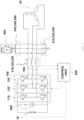
FIG. 1 is a circuit diagram of a rapid charge/discharge system according to a first embodiment of the present invention. -
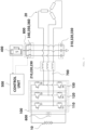
FIG. 2 is a circuit diagram of a rapid charge/discharge system according to a second embodiment of the present invention. -
FIG. 3 is a schematic diagram of a rapid charge/discharge system according to a modification of the first embodiment of the present invention. -
FIG. 4 is a flow chart of a charge/discharge operation of the rapid charge/discharge system according to the first embodiment of the present invention. - The aforementioned objects, features and advantages of the present invention will be apparent from the embodiments to be described below with reference to the accompanying drawings. The following specific structural or functional descriptions are provided merely for the purpose of describing embodiments according to the concept of the present invention, and the embodiments according to the concept of the present invention can be implemented in various forms and should not be construed as being limited to the embodiments set forth herein. Since various modifications may be made to the embodiments according to the concept of the present invention, and the embodiments of the present disclosure may have various forms, specific embodiments will be illustrated in the drawings and described in detail hereinbelow. However, this is not intended to limit the embodiments according to the concept of the present invention to specific forms disclosed herein, and it should be noted that the specific embodiments described herein cover all modifications, equivalents, or substitutes within the spirit and technical scope of the present invention. Terms "first", "second", and/or the like may be used to describe various components but the components are not limited by the above terms. The above terms are only used to distinguish one component from another component. For example, a first component may be referred to as a second component, and similarly, a second component may be referred to as a first component, without departing from the scope according to the concept of the present disclosure. It should be noted that, when one component is referred to as being "coupled" or "connected" to another component, the one element may be directly coupled or connected to the another element, or the one element may be coupled or connected to the another element through an intervening component therebetween. On the other hand, when one component is referred to as being "directly coupled" to or "directly connected" to another component, there is no intervening component therebetween. Other expressions for describing relationships between components, that is, expressions such as "between", "immediately between", "adjacent to", and "directly adjacent to" shall be construed similarly. Terms used herein are used only to describe the specific embodiments and are not intended to limit the present invention. Singular expressions include plural expressions unless the context clearly indicates otherwise. It should be noted that terms "include", "have", and the like used herein are intended to specify the presence of stated features, numbers, steps, operations, components, parts, or combinations thereof but do not preclude the presence or addition of one or more other features, numbers, steps, operations, components, parts, or combinations thereof. Unless otherwise defined, all terms used herein, including technical or scientific terms, have the same meanings as those generally understood by those skilled in the art to which the present invention pertains. The terms defined in generally used dictionaries and the like should be interpreted as having the same meanings as those in the context of the related art, and should not be interpreted as having ideal or excessively formal meanings unless clearly defined herein. Hereinafter, the present invention will be described in detail by describing preferred embodiments of the present invention with reference to the accompanying drawings. Like reference signs between the drawings indicate like elements.
-
FIG. 1 is a circuit diagram of a rapid charge/discharge system according to a first embodiment of the present invention. - As illustrated in
FIG. 1 , the rapid charge/discharge system according to the present invention may include aninverter 100, a first inductor 210 to a third inductor 230, a first capacitor 310 to a third capacitor 330, a first terminal 340 to a third terminal 360, aload 400, and acontrol unit 500. - The
inverter 100 is a voltage type inverter that is connected to abattery 10 of an electric vehicle to control charging and discharging of thebattery 10. Theinverter 100 includes afirst switch leg 110 to athird switch leg 130. Thefirst switch leg 110 to thethird switch leg 130 are formed to correspond to three phases of amotor 20, respectively, and may be connected to each other in parallel and may also be connected to thebattery 10 in parallel. Each of thefirst switch leg 110 to thethird switch leg 130 includes two switches connected in series with each other, and the switches included in thefirst switch leg 110 to thethird switch leg 130 will be referred to as a first switch S1 to a sixth switch S6, respectively. The first switch S1 to the sixth switch S6 are controlled by acontrol unit 500 to be described below. - One end of each of the first inductor 210 to the third inductor 230 is connected to a node between the two switches included in the corresponding one of the
first switch leg 110 to thethird switch leg 130, and the other end of each of the first inductor 210 to the third inductor 230 is connected to a corresponding one of three-phase windings of themotor 20. - One end of each of the first capacitor 310 to the third capacitor 330 is connected to the other end of the corresponding one of the first inductor 210 to the third inductor 230, and the other end of each of the first capacitor 310 to the third capacitor 330 is grounded.
- By employing an LC network including the first inductor 210 to the third inductor 230 and the first capacitor 310 to the third capacitor 330, the rapid charge/discharge system according to the present invention is capable of driving a high-speed motor that could not be driven when the voltage of the
inverter 100 is restricted to lower than the maximum voltage. Also, the dynamic characteristics of the LC network significantly reduce switching noise generated in the inverter and introduced into themotor 20, thereby maximizing the winding insulation resistance of themotor 20, which is helpful in extending the lifespan of themotor 20. - One end of each of the first terminal 340 to the third terminal 360 is connected to the other end of the corresponding one of the first inductor 210 to the third inductor 230, and the other end of each of the first terminal 340 to the third terminal 360 is connected to the
load 400 to be described below. - The first terminal 340 to the third terminal 360 are provided for connection to the
load 400, and serve as ports for receiving power from the load 400 (charging operation) or transferring power to the load 400 (discharging operation). - The
load 400 may be a charging load or a discharging load. When theload 400 is a charging load, the charging load may be a direct current. The direct current supplied from theload 400 is stepped up by theinverter 100 through the first inductor 210 to the third inductor 230, and then transferred to thebattery 10 to charge thebattery 10. Theload 400 transfers the power to thebattery 10 in contact with all of the first terminal 340 to the third terminal 360, and the first terminal 340 to the third terminal 360 are electrically connected to all of the three phases of themotor 20, such that the phases of themotor 20 have the same voltage and are shorted. As a result, no current flows from theload 400 to themotor 20. - The
control unit 500 controls the switches included in theinverter 100 to be in a charging mode or a discharging mode depending on the type of theload 400. Thecontrol unit 500 may be implemented by a device including a kind of electronic device, and may be connected to each of the switches included in theinverter 100 in a wired manner or in a wireless manner to apply a control signal to each of the switches included in theinverter 100. According to an exemplary embodiment of the present disclosure, thecontrol unit 500 may include a processor (e.g., computer, microprocessor, CPU, ASIC, circuitry, logic circuits, etc.) and an associated non-transitory memory storing software instructions which, when executed by the processor, provides the functionalities of thecontrol unit 500. Herein, the memory and the processor may be implemented as separate semiconductor circuits. Alternatively, the memory and the processor may be implemented as a single integrated semiconductor circuit. The processor may embody one or more processor(s). - As illustrated in
FIG. 1 , the rapid charge/discharge system according to the first embodiment of the present invention further includes aDC link capacitor 600. TheDC link capacitor 600 is connected to thebattery 10 in parallel. - The
control unit 500 controls the switches included in theinverter 100 according to a voltage of theload 400, a current flowing through the first inductor 210 to the third inductor 230, and a voltage of theDC link capacitor 600. Thecontrol unit 500 may charge or discharge thebattery 10 by controlling the switches included in theinverter 100 using various methods such as frequency control, PWM control, and PI control. In addition, thecontrol unit 500 may control theinverter 100 in controlling themotor 20 while a normal electric vehicle is operating, that is, driving. Since onecontrol unit 500 is responsible for not only charging and discharging thebattery 10 but also controlling themotor 20, there is no need to add another control unit, thereby simplifying the system. - Through the above-described configuration of the present invention, it is possible to apply an active LC network that enables driving at the maximum speed with the maximum torque even under lower than the maximum voltage, beyond an existing passive driving configuration such as an inverter-motor combination. By using such an LC network, a rapid charge/discharge system, for example, for 800V charging, can be implemented without any additional device other than the LC network.
- In order to acquire information on the current flowing through the first inductor 210 to the third inductor 230 and the voltage of the
DC link capacitor 600 from thecontrol unit 500, the rapid charge/discharge system according to the first embodiment of the present invention may further include acurrent sensor 700, a first voltage sensor, and a second voltage sensor as illustrated inFIG. 1 . - The
current sensor 700 is located between the first inductor 210 to the third inductor 230 and thefirst switch leg 110 to thethird switch leg 130 to sense a current flowing through the first inductor 210 to the third inductor 230. Although only onecurrent sensor 700 is illustrated in the drawing, the current sensor may be installed in each of the first inductor 210 to the third inductor 230 to sense a current flowing in each of the three phases. - The first voltage sensor senses a voltage between each of the first inductor 210 to the third inductor 230 and the
motor 20 to sense a voltage from theload 400. Since both ends of the first voltage sensor need to be connected to each of the first inductor 210 to the third inductor 320 and the ground, the first voltage sensor is not particularly illustrated in the drawing. - The second voltage sensor is disposed at one end of the
DC link capacitor 600 to sense a voltage of theDC link capacitor 600. The second voltage sensor is also not particularly illustrated in the drawing. Since theDC link capacitor 600 is connected to thebattery 10 in parallel, the second voltage sensor substantially senses a voltage of thebattery 10. - Each of the
current sensor 700, the first voltage sensor, and the second voltage sensor may transmit a sensed value to thecontrol unit 500, and to this end, the sensors and thecontrol unit 500 may include respective communication modules according to a predetermined communication protocol. -
FIG. 2 is a circuit diagram of a rapid charge/discharge system according to a second embodiment of the present invention. - In some cases, it may be difficult to sense a voltage from the
load 400. In this case, as illustrated inFIG. 2 , the rapid charge/discharge system according to the second embodiment of the present invention may directly transmit charging voltage information from theload 400 to thecontrol unit 500. To this end, theload 400 and thecontrol unit 500 may be connected to each other to transmit and receive signals, and each of theload 400 and thecontrol unit 500 may include respective communication modules according to a predetermined communication protocol. In this case, the communication protocol is a power line communication (PLC) or a controller area network (CAN). -
FIG. 3 is a schematic diagram of a rapid charge/discharge system according to a modification of the first embodiment of the present invention. - As illustrated in
FIG. 3 , the rapid charge/discharge system according to the modification of the first embodiment of the present invention further includes arelay 800. - The
relay 800 may be controlled by thecontrol unit 500, and may determine whether to connect the first terminal 340 to the third terminal 360 and theload 400 to each other. Threerelays 800 may be formed to correspond to the first terminal 340 to the third terminal 360, respectively. Therelay 800 is turned on to electrically connect theload 400 and the first terminal 340 to the third terminal 360 to each other, and therelay 800 is turned off to electrically disconnect theload 400 and the first terminal 340 to the third terminal 360 from each other. - The
relay 800 may be mechanical or electronic. When therelay 800 is implemented electronically, a fastening lock button on a station, that is, theload 400, which is a rapid charger, needs to be configured to be driven together with the relay. Here, the fastening lock may refer to a kind of mechanical/electrical device that maintains the state of therelay 800 when therelay 800 is turned on or off. The fastening lock button and therelay 800 may be electronically driven together, or the fastening locking button may be manually driven independently from therelay 800 even though therelay 800 is driven electronically. -
FIG. 4 is a flow chart of a charge/discharge operation of the rapid charge/discharge system according to the first embodiment of the present invention. - The rapid charge/discharge system according to various embodiments of the present invention may include a vehicle to everything (V2X) function. V2X means that a vehicle exchanges information with objects such as other vehicles, mobile devices, and roads through wired and wireless networks. Also, V2X does not simply mean transfer of information, and may mean that an electric vehicle equipped with the
battery 10 serves as a kind of power supply by supplying power stored in thebattery 10. When the V2X function is performed, theload 400 may become a discharge load that consumes power, and at this time, the power stored in thebattery 10 may be stepped down through the operation of theinverter 100 and then supplied to theload 400. - As illustrated in
FIG. 4 , thecontrol unit 500 may initialize an existing V2X connection before the V2X function is performed by the rapid charge/discharge system according to the first embodiment of the present invention. In the process of initializing the V2X connection, thecontrol unit 500 may monitor the rapid charge/discharge system according to the present invention through information received from each of the sensors. More specifically, thecontrol unit 500 determines that an initialization error has occurred when a position of a rotor of themotor 20 is changed or when an initial charging time does not match a set value due to nonuniform contact, which generates a phase current in the motor. Thereafter, thecontrol unit 500 may store an initialization error occurrence record, and stop the operation of theinverter 100 by turning off therelay 800. - After the V2X function is initialized, even when a normal (charging or discharging) operation is performed, the
control unit 500 may monitor whether the system operates normally through information received from each of the sensors. More specifically, after the initialization, when a phase deviation of a three-phase current of themotor 20 is greater than a reference value, thecontrol unit 500 stores a contact defect occurrence record, and stops the operation of theinverter 100 by turning off therelay 800. - In addition, when an RPS value changes during normal operation, the
control unit 500 stores a contact defect occurrence record, and stops the operation of theinverter 100 by turning off therelay 800. - When the charging or discharging operation of the rapid charge/discharge system according to the present invention is stopped, the
control unit 500 discharges the first inductor 210 to the third inductor 230 and the first capacitor 310 to the third capacitor 330 before the charging or discharging operation is stopped. The foregoing operation of thecontrol unit 500 is to prevent themotor 20 from being driven by power remaining in the first inductor 210 to the third inductor 230 and the first capacitor 310 to the third capacitor 330. However, an error may occur even while the first inductor 210 to the third inductor 230 and the first capacitor 310 to the third capacitor 330 are being discharged. More specifically, during the process of discharging the first inductor 210 to the third inductor 230 and the first capacitor 310 to the third capacitor 330, when a discharge voltage time constant is out of a reference value or a reference range, thecontrol unit 500 stores a discharge error occurrence record, turns off therelay 800, and stops the operation of theinverter 100. - The rapid charge/discharge system according to the first embodiment of the present invention may further include a separate memory unit for storing the error occurrence records.
- Although the preferred embodiments of the present invention have been described above, the embodiments disclosed herein are not intended to limit the technical idea of the present invention, but are provided to explain the technical idea of the present invention. Therefore, the technical idea of the present invention includes not only each of the embodiments disclosed herein but also a combination of the embodiments disclosed here, and furthermore, the scope of the technical idea of the present invention is not limited by these embodiments. In addition, those skilled in the art to which the present invention pertains may make numerous changes and modifications to the present invention without departing from the spirit and scope of the appended claims, and all of such appropriate changes and modifications shall be regarded as falling within the scope of the present invention as equivalents.
Claims (11)
- A rapid charge and discharge system comprising:an inverter connected to a battery and including first to third switch legs to operate to charge or discharge the battery, the inverter including a plurality of switches;first to third inductors each having one end connected to a node between two switches included in a corresponding one of the first to third switch legs of the plurality of switches, and the other end connected to a corresponding one of three phases of a motor;first to third capacitors each having one end connected to the other end of a corresponding one of the first to third inductors, and the other end being grounded;first to third terminals each having one end connected to the other end of a corresponding one of the first to third inductors;a load connected to the first to third terminals; anda control unit controlling at least one of the plurality of switches included in the inverter to be in a charging mode or a discharging mode according to a type of the load.
- The rapid charge and discharge system of claim 1, wherein all of the other ends of the first to third terminals are connected to the load, such that the three phases of the motor are shorted.
- The rapid charge and discharge system of claim 1 or 2, further comprising a DC link capacitor connected to the battery in parallel.
- The rapid charge and discharge system of claim 3, further comprising:a current sensor sensing a current flowing between the first to third inductors and the first to third switch legs;a first voltage sensor sensing a voltage between the first to third inductors and the motor; anda second voltage sensor sensing a voltage of the DC link capacitor,wherein the control unit controls the at least one of the plurality of switches included in the inverter using values sensed by the current sensor, the first voltage sensor, and the second voltage sensor.
- The rapid charge and discharge system of claim 3 or 4, further comprising:a current sensor sensing a current flowing between the first to third inductors and the first to third switch legs; anda second voltage sensor sensing a voltage of the DC link capacitor,wherein the load is a charging load that transmits charging voltage information to the control unit, andthe control unit controls the at least one of the plurality of switches included in the inverter using values sensed by the current sensor and the second voltage sensor with the charging voltage information received from the charging load.
- The rapid charge and discharge system of any one of claims 2 to 5, further comprising: a relay, controlled by the control unit, determines whether to connect the first to third terminals and the load to each other.
- The rapid charge and discharge system of claim 6, wherein the control unit performs initialization when the load is connected to the first to third terminals, and
during the initialization, when a phase current is generated in the motor or a position of a rotor of the motor is changed, the control unit stores an initialization error occurrence record, and controls the relay to be turned off or stops the operation of the inverter. - The rapid charge and discharge system of claim 7, wherein the control unit controls the inverter to be in the charging mode or the discharging mode after the initialization, and
when a phase deviation of a three-phase current of the motor is greater than a reference value, the control unit stores a contact defect occurrence record, and controls the relay to be turned off or stops the operation of the inverter. - The rapid charge and discharge system of claim 7 or 8, wherein after the initialization, the control unit controls the inverter to be in the charging mode or the discharging mode, and
when an RPS value changes, the control unit stores a contact defect occurrence record, and controls the relay to be turned off or stops the operation of the inverter. - The rapid charge and discharge system of any one of claims 7 to 9, wherein after the initialization, the control unit stops the operation of the inverter after discharging the first to third inductors and the first to third capacitors.
- The rapid charge and discharge system of claim 10, wherein in a process of discharging the first to third inductors and the first to third capacitors, when a discharge voltage time constant is out of a reference value, the control unit stores a discharge error occurrence record, and controls the relay to be turned off or stops the operation of the inverter.
Applications Claiming Priority (1)
| Application Number | Priority Date | Filing Date | Title |
|---|---|---|---|
| KR1020220186975A KR20240104586A (en) | 2022-12-28 | 2022-12-28 | Rapid charge/discharge system |
Publications (2)
| Publication Number | Publication Date |
|---|---|
| EP4393763A1 true EP4393763A1 (en) | 2024-07-03 |
| EP4393763B1 EP4393763B1 (en) | 2025-12-17 |
Family
ID=88598898
Family Applications (1)
| Application Number | Title | Priority Date | Filing Date |
|---|---|---|---|
| EP23206325.5A Active EP4393763B1 (en) | 2022-12-28 | 2023-10-27 | Rapid charge/discharge system |
Country Status (4)
| Country | Link |
|---|---|
| US (1) | US12388386B2 (en) |
| EP (1) | EP4393763B1 (en) |
| KR (1) | KR20240104586A (en) |
| CN (1) | CN118263942A (en) |
Families Citing this family (1)
| Publication number | Priority date | Publication date | Assignee | Title |
|---|---|---|---|---|
| US12470155B2 (en) * | 2023-10-23 | 2025-11-11 | Schaeffler Technologies AG & Co. KG | Power electronics for voltage boost charging |
Citations (6)
| Publication number | Priority date | Publication date | Assignee | Title |
|---|---|---|---|---|
| CN102201693A (en) * | 2011-06-07 | 2011-09-28 | 天宝电子(惠州)有限公司 | Vehicle-mounted charging system of electric vehicle |
| DE102011075927A1 (en) * | 2011-05-16 | 2012-11-22 | Fraunhofer-Gesellschaft zur Förderung der angewandten Forschung e.V. | Multifunctional power converter circuit for switching switching-network into different switching states during e.g. charging high-volt battery in electric car, has inductor connected to terminal for providing voltage to another terminal |
| US9331515B2 (en) * | 2011-02-09 | 2016-05-03 | Robert Bosch Gmbh | System for charging an energy store, and method for operating the charging system |
| CN110780174A (en) * | 2019-12-04 | 2020-02-11 | 深圳威迈斯新能源股份有限公司 | Insulation detection method and circuit for single-three phase inverter of bidirectional vehicle-mounted charger |
| CN107437806B (en) * | 2016-05-27 | 2020-06-19 | 比亚迪股份有限公司 | Vehicle-mounted filtering device, vehicle-mounted charging equipment and vehicle |
| KR102282679B1 (en) | 2021-02-03 | 2021-07-28 | (주)그린파워 | Direct Charging Device for Electric Vehicle |
Family Cites Families (2)
| Publication number | Priority date | Publication date | Assignee | Title |
|---|---|---|---|---|
| KR102454222B1 (en) * | 2017-07-21 | 2022-10-17 | 현대자동차주식회사 | Electric vehicle |
| US12233716B2 (en) * | 2022-09-23 | 2025-02-25 | Ford Global Technologies, Llc | Automotive electric drive with three phase coupled inverter |
-
2022
- 2022-12-28 KR KR1020220186975A patent/KR20240104586A/en active Pending
-
2023
- 2023-10-24 US US18/383,176 patent/US12388386B2/en active Active
- 2023-10-27 EP EP23206325.5A patent/EP4393763B1/en active Active
- 2023-12-21 CN CN202311781330.4A patent/CN118263942A/en active Pending
Patent Citations (6)
| Publication number | Priority date | Publication date | Assignee | Title |
|---|---|---|---|---|
| US9331515B2 (en) * | 2011-02-09 | 2016-05-03 | Robert Bosch Gmbh | System for charging an energy store, and method for operating the charging system |
| DE102011075927A1 (en) * | 2011-05-16 | 2012-11-22 | Fraunhofer-Gesellschaft zur Förderung der angewandten Forschung e.V. | Multifunctional power converter circuit for switching switching-network into different switching states during e.g. charging high-volt battery in electric car, has inductor connected to terminal for providing voltage to another terminal |
| CN102201693A (en) * | 2011-06-07 | 2011-09-28 | 天宝电子(惠州)有限公司 | Vehicle-mounted charging system of electric vehicle |
| CN107437806B (en) * | 2016-05-27 | 2020-06-19 | 比亚迪股份有限公司 | Vehicle-mounted filtering device, vehicle-mounted charging equipment and vehicle |
| CN110780174A (en) * | 2019-12-04 | 2020-02-11 | 深圳威迈斯新能源股份有限公司 | Insulation detection method and circuit for single-three phase inverter of bidirectional vehicle-mounted charger |
| KR102282679B1 (en) | 2021-02-03 | 2021-07-28 | (주)그린파워 | Direct Charging Device for Electric Vehicle |
Also Published As
| Publication number | Publication date |
|---|---|
| US12388386B2 (en) | 2025-08-12 |
| KR20240104586A (en) | 2024-07-05 |
| US20240223115A1 (en) | 2024-07-04 |
| CN118263942A (en) | 2024-06-28 |
| EP4393763B1 (en) | 2025-12-17 |
Similar Documents
| Publication | Publication Date | Title |
|---|---|---|
| EP3621174B1 (en) | Method and apparatus for charging and discharging | |
| US6923279B2 (en) | Power supply apparatus and electric vehicle using the same | |
| US11865934B2 (en) | Electric vehicle, and integrated controller and integrated control system thereof | |
| US6737756B1 (en) | Power supply for an automotive vehicle using DC-to-DC converter for charge transfer | |
| US20240343146A1 (en) | Discharging vehicle and vehicle charging system | |
| CN105270295B (en) | On-board electrical systems for motor vehicles | |
| CN105264761A (en) | Discharge control device | |
| JP2018103972A (en) | On-vehicle control device | |
| US12388386B2 (en) | Rapid charge/discharge system | |
| US20240178697A1 (en) | Battery and power storage system | |
| US20240174132A1 (en) | Vehicle | |
| US20240113531A1 (en) | Power storage system | |
| US6215277B1 (en) | Electrical charging system | |
| KR20170114545A (en) | Vehicle power control device and method | |
| JP2009050154A (en) | Power converter system for automotive vehicle | |
| EP3540902B1 (en) | Power supply system including high-voltage system and low-voltage system | |
| KR101759739B1 (en) | Apparatus for determining switch error in bidirectional dc-dc converter and method thereof | |
| JP2022035987A (en) | Switching power supply device, vehicle and control method | |
| US12466278B2 (en) | Power storage system | |
| JP2025101822A (en) | Power Conversion Equipment | |
| EP4656442A1 (en) | On-board charging apparatus for charging a battery of an electrified vehicle | |
| JP7763882B2 (en) | Powered Device | |
| US9937807B2 (en) | Battery charger, electrical system and motor vehicle | |
| WO2026069734A1 (en) | In-vehicle power receiver with check of short-circuit function and wireless power transfer system | |
| WO2026069733A1 (en) | Wireless power receiver comprising short-circuit operation check and system |
Legal Events
| Date | Code | Title | Description |
|---|---|---|---|
| PUAI | Public reference made under article 153(3) epc to a published international application that has entered the european phase |
Free format text: ORIGINAL CODE: 0009012 |
|
| STAA | Information on the status of an ep patent application or granted ep patent |
Free format text: STATUS: THE APPLICATION HAS BEEN PUBLISHED |
|
| AK | Designated contracting states |
Kind code of ref document: A1 Designated state(s): AL AT BE BG CH CY CZ DE DK EE ES FI FR GB GR HR HU IE IS IT LI LT LU LV MC ME MK MT NL NO PL PT RO RS SE SI SK SM TR |
|
| STAA | Information on the status of an ep patent application or granted ep patent |
Free format text: STATUS: REQUEST FOR EXAMINATION WAS MADE |
|
| 17P | Request for examination filed |
Effective date: 20250103 |
|
| STAA | Information on the status of an ep patent application or granted ep patent |
Free format text: STATUS: EXAMINATION IS IN PROGRESS |
|
| 17Q | First examination report despatched |
Effective date: 20250318 |
|
| GRAP | Despatch of communication of intention to grant a patent |
Free format text: ORIGINAL CODE: EPIDOSNIGR1 |
|
| STAA | Information on the status of an ep patent application or granted ep patent |
Free format text: STATUS: GRANT OF PATENT IS INTENDED |
|
| INTG | Intention to grant announced |
Effective date: 20250715 |
|
| GRAS | Grant fee paid |
Free format text: ORIGINAL CODE: EPIDOSNIGR3 |
|
| GRAA | (expected) grant |
Free format text: ORIGINAL CODE: 0009210 |
|
| STAA | Information on the status of an ep patent application or granted ep patent |
Free format text: STATUS: THE PATENT HAS BEEN GRANTED |
|
| AK | Designated contracting states |
Kind code of ref document: B1 Designated state(s): AL AT BE BG CH CY CZ DE DK EE ES FI FR GB GR HR HU IE IS IT LI LT LU LV MC ME MK MT NL NO PL PT RO RS SE SI SK SM TR |
|
| P01 | Opt-out of the competence of the unified patent court (upc) registered |
Free format text: CASE NUMBER: UPC_APP_0012497_4393763/2025 Effective date: 20251107 |
|
| REG | Reference to a national code |
Ref country code: CH Ref legal event code: F10 Free format text: ST27 STATUS EVENT CODE: U-0-0-F10-F00 (AS PROVIDED BY THE NATIONAL OFFICE) Effective date: 20251217 Ref country code: GB Ref legal event code: FG4D |
|
| REG | Reference to a national code |
Ref country code: DE Ref legal event code: R096 Ref document number: 602023009791 Country of ref document: DE |
|
| REG | Reference to a national code |
Ref country code: LT Ref legal event code: MG9D |
|
| PG25 | Lapsed in a contracting state [announced via postgrant information from national office to epo] |
Ref country code: NO Free format text: LAPSE BECAUSE OF FAILURE TO SUBMIT A TRANSLATION OF THE DESCRIPTION OR TO PAY THE FEE WITHIN THE PRESCRIBED TIME-LIMIT Effective date: 20260317 |
|
| PG25 | Lapsed in a contracting state [announced via postgrant information from national office to epo] |
Ref country code: FI Free format text: LAPSE BECAUSE OF FAILURE TO SUBMIT A TRANSLATION OF THE DESCRIPTION OR TO PAY THE FEE WITHIN THE PRESCRIBED TIME-LIMIT Effective date: 20251217 Ref country code: HR Free format text: LAPSE BECAUSE OF FAILURE TO SUBMIT A TRANSLATION OF THE DESCRIPTION OR TO PAY THE FEE WITHIN THE PRESCRIBED TIME-LIMIT Effective date: 20251217 |
|
| PG25 | Lapsed in a contracting state [announced via postgrant information from national office to epo] |
Ref country code: RS Free format text: LAPSE BECAUSE OF FAILURE TO SUBMIT A TRANSLATION OF THE DESCRIPTION OR TO PAY THE FEE WITHIN THE PRESCRIBED TIME-LIMIT Effective date: 20260317 |
|
| REG | Reference to a national code |
Ref country code: NL Ref legal event code: MP Effective date: 20251217 |
|
| PG25 | Lapsed in a contracting state [announced via postgrant information from national office to epo] |
Ref country code: LV Free format text: LAPSE BECAUSE OF FAILURE TO SUBMIT A TRANSLATION OF THE DESCRIPTION OR TO PAY THE FEE WITHIN THE PRESCRIBED TIME-LIMIT Effective date: 20251217 |
|
| PG25 | Lapsed in a contracting state [announced via postgrant information from national office to epo] |
Ref country code: BG Free format text: LAPSE BECAUSE OF FAILURE TO SUBMIT A TRANSLATION OF THE DESCRIPTION OR TO PAY THE FEE WITHIN THE PRESCRIBED TIME-LIMIT Effective date: 20251217 |
|
| REG | Reference to a national code |
Ref country code: AT Ref legal event code: MK05 Ref document number: 1868215 Country of ref document: AT Kind code of ref document: T Effective date: 20251217 |
|
| PG25 | Lapsed in a contracting state [announced via postgrant information from national office to epo] |
Ref country code: NL Free format text: LAPSE BECAUSE OF FAILURE TO SUBMIT A TRANSLATION OF THE DESCRIPTION OR TO PAY THE FEE WITHIN THE PRESCRIBED TIME-LIMIT Effective date: 20251217 |
|
| PG25 | Lapsed in a contracting state [announced via postgrant information from national office to epo] |
Ref country code: LT Free format text: LAPSE BECAUSE OF FAILURE TO SUBMIT A TRANSLATION OF THE DESCRIPTION OR TO PAY THE FEE WITHIN THE PRESCRIBED TIME-LIMIT Effective date: 20251217 |
|
| PG25 | Lapsed in a contracting state [announced via postgrant information from national office to epo] |
Ref country code: SM Free format text: LAPSE BECAUSE OF FAILURE TO SUBMIT A TRANSLATION OF THE DESCRIPTION OR TO PAY THE FEE WITHIN THE PRESCRIBED TIME-LIMIT Effective date: 20251217 |
|
| PG25 | Lapsed in a contracting state [announced via postgrant information from national office to epo] |
Ref country code: ES Free format text: LAPSE BECAUSE OF FAILURE TO SUBMIT A TRANSLATION OF THE DESCRIPTION OR TO PAY THE FEE WITHIN THE PRESCRIBED TIME-LIMIT Effective date: 20251217 |
|
| PG25 | Lapsed in a contracting state [announced via postgrant information from national office to epo] |
Ref country code: PL Free format text: LAPSE BECAUSE OF FAILURE TO SUBMIT A TRANSLATION OF THE DESCRIPTION OR TO PAY THE FEE WITHIN THE PRESCRIBED TIME-LIMIT Effective date: 20251217 |
|
| PG25 | Lapsed in a contracting state [announced via postgrant information from national office to epo] |
Ref country code: IT Free format text: LAPSE BECAUSE OF FAILURE TO SUBMIT A TRANSLATION OF THE DESCRIPTION OR TO PAY THE FEE WITHIN THE PRESCRIBED TIME-LIMIT Effective date: 20251217 |
|
| PG25 | Lapsed in a contracting state [announced via postgrant information from national office to epo] |
Ref country code: AT Free format text: LAPSE BECAUSE OF FAILURE TO SUBMIT A TRANSLATION OF THE DESCRIPTION OR TO PAY THE FEE WITHIN THE PRESCRIBED TIME-LIMIT Effective date: 20251217 |
|
| PG25 | Lapsed in a contracting state [announced via postgrant information from national office to epo] |
Ref country code: EE Free format text: LAPSE BECAUSE OF FAILURE TO SUBMIT A TRANSLATION OF THE DESCRIPTION OR TO PAY THE FEE WITHIN THE PRESCRIBED TIME-LIMIT Effective date: 20251217 |
|
| PG25 | Lapsed in a contracting state [announced via postgrant information from national office to epo] |
Ref country code: PT Free format text: LAPSE BECAUSE OF FAILURE TO SUBMIT A TRANSLATION OF THE DESCRIPTION OR TO PAY THE FEE WITHIN THE PRESCRIBED TIME-LIMIT Effective date: 20260417 Ref country code: IS Free format text: LAPSE BECAUSE OF FAILURE TO SUBMIT A TRANSLATION OF THE DESCRIPTION OR TO PAY THE FEE WITHIN THE PRESCRIBED TIME-LIMIT Effective date: 20260417 |
|
| PG25 | Lapsed in a contracting state [announced via postgrant information from national office to epo] |
Ref country code: CZ Free format text: LAPSE BECAUSE OF FAILURE TO SUBMIT A TRANSLATION OF THE DESCRIPTION OR TO PAY THE FEE WITHIN THE PRESCRIBED TIME-LIMIT Effective date: 20251217 |
|
| PG25 | Lapsed in a contracting state [announced via postgrant information from national office to epo] |
Ref country code: SK Free format text: LAPSE BECAUSE OF FAILURE TO SUBMIT A TRANSLATION OF THE DESCRIPTION OR TO PAY THE FEE WITHIN THE PRESCRIBED TIME-LIMIT Effective date: 20251217 |
|
| PG25 | Lapsed in a contracting state [announced via postgrant information from national office to epo] |
Ref country code: SE Free format text: LAPSE BECAUSE OF FAILURE TO SUBMIT A TRANSLATION OF THE DESCRIPTION OR TO PAY THE FEE WITHIN THE PRESCRIBED TIME-LIMIT Effective date: 20251217 |