EP4393744A1 - Picture generating apparatus for use in head-up display - Google Patents
Picture generating apparatus for use in head-up display Download PDFInfo
- Publication number
- EP4393744A1 EP4393744A1 EP23165468.2A EP23165468A EP4393744A1 EP 4393744 A1 EP4393744 A1 EP 4393744A1 EP 23165468 A EP23165468 A EP 23165468A EP 4393744 A1 EP4393744 A1 EP 4393744A1
- Authority
- EP
- European Patent Office
- Prior art keywords
- funnel
- lcd
- light
- diffuser
- reflector
- Prior art date
- Legal status (The legal status is an assumption and is not a legal conclusion. Google has not performed a legal analysis and makes no representation as to the accuracy of the status listed.)
- Granted
Links
Images



Classifications
-
- G—PHYSICS
- G02—OPTICS
- G02B—OPTICAL ELEMENTS, SYSTEMS OR APPARATUS
- G02B27/00—Optical systems or apparatus not provided for by any of the groups G02B1/00 - G02B26/00, G02B30/00
- G02B27/01—Head-up displays
- G02B27/0101—Head-up displays characterised by optical features
-
- G—PHYSICS
- G02—OPTICS
- G02B—OPTICAL ELEMENTS, SYSTEMS OR APPARATUS
- G02B27/00—Optical systems or apparatus not provided for by any of the groups G02B1/00 - G02B26/00, G02B30/00
- G02B27/01—Head-up displays
- G02B27/017—Head mounted
- G02B27/0176—Head mounted characterised by mechanical features
-
- G—PHYSICS
- G02—OPTICS
- G02F—OPTICAL DEVICES OR ARRANGEMENTS FOR THE CONTROL OF LIGHT BY MODIFICATION OF THE OPTICAL PROPERTIES OF THE MEDIA OF THE ELEMENTS INVOLVED THEREIN; NON-LINEAR OPTICS; FREQUENCY-CHANGING OF LIGHT; OPTICAL LOGIC ELEMENTS; OPTICAL ANALOGUE/DIGITAL CONVERTERS
- G02F1/00—Devices or arrangements for the control of the intensity, colour, phase, polarisation or direction of light arriving from an independent light source, e.g. switching, gating or modulating; Non-linear optics
- G02F1/01—Devices or arrangements for the control of the intensity, colour, phase, polarisation or direction of light arriving from an independent light source, e.g. switching, gating or modulating; Non-linear optics for the control of the intensity, phase, polarisation or colour
- G02F1/13—Devices or arrangements for the control of the intensity, colour, phase, polarisation or direction of light arriving from an independent light source, e.g. switching, gating or modulating; Non-linear optics for the control of the intensity, phase, polarisation or colour based on liquid crystals, e.g. single liquid crystal display cells
- G02F1/133—Constructional arrangements; Operation of liquid crystal cells; Circuit arrangements
- G02F1/1333—Constructional arrangements; Manufacturing methods
- G02F1/1335—Structural association of cells with optical devices, e.g. polarisers or reflectors
- G02F1/1336—Illuminating devices
- G02F1/133602—Direct backlight
- G02F1/133603—Direct backlight with LEDs
-
- B—PERFORMING OPERATIONS; TRANSPORTING
- B60—VEHICLES IN GENERAL
- B60K—ARRANGEMENT OR MOUNTING OF PROPULSION UNITS OR OF TRANSMISSIONS IN VEHICLES; ARRANGEMENT OR MOUNTING OF PLURAL DIVERSE PRIME-MOVERS IN VEHICLES; AUXILIARY DRIVES FOR VEHICLES; INSTRUMENTATION OR DASHBOARDS FOR VEHICLES; ARRANGEMENTS IN CONNECTION WITH COOLING, AIR INTAKE, GAS EXHAUST OR FUEL SUPPLY OF PROPULSION UNITS IN VEHICLES
- B60K35/00—Instruments specially adapted for vehicles; Arrangement of instruments in or on vehicles
-
- B—PERFORMING OPERATIONS; TRANSPORTING
- B60—VEHICLES IN GENERAL
- B60K—ARRANGEMENT OR MOUNTING OF PROPULSION UNITS OR OF TRANSMISSIONS IN VEHICLES; ARRANGEMENT OR MOUNTING OF PLURAL DIVERSE PRIME-MOVERS IN VEHICLES; AUXILIARY DRIVES FOR VEHICLES; INSTRUMENTATION OR DASHBOARDS FOR VEHICLES; ARRANGEMENTS IN CONNECTION WITH COOLING, AIR INTAKE, GAS EXHAUST OR FUEL SUPPLY OF PROPULSION UNITS IN VEHICLES
- B60K35/00—Instruments specially adapted for vehicles; Arrangement of instruments in or on vehicles
- B60K35/20—Output arrangements, i.e. from vehicle to user, associated with vehicle functions or specially adapted therefor
- B60K35/21—Output arrangements, i.e. from vehicle to user, associated with vehicle functions or specially adapted therefor using visual output, e.g. blinking lights or matrix displays
- B60K35/23—Head-up displays [HUD]
- B60K35/231—Head-up displays [HUD] characterised by their arrangement or structure for integration into vehicles
-
- B—PERFORMING OPERATIONS; TRANSPORTING
- B60—VEHICLES IN GENERAL
- B60K—ARRANGEMENT OR MOUNTING OF PROPULSION UNITS OR OF TRANSMISSIONS IN VEHICLES; ARRANGEMENT OR MOUNTING OF PLURAL DIVERSE PRIME-MOVERS IN VEHICLES; AUXILIARY DRIVES FOR VEHICLES; INSTRUMENTATION OR DASHBOARDS FOR VEHICLES; ARRANGEMENTS IN CONNECTION WITH COOLING, AIR INTAKE, GAS EXHAUST OR FUEL SUPPLY OF PROPULSION UNITS IN VEHICLES
- B60K35/00—Instruments specially adapted for vehicles; Arrangement of instruments in or on vehicles
- B60K35/50—Instruments characterised by their means of attachment to or integration in the vehicle
-
- G—PHYSICS
- G02—OPTICS
- G02B—OPTICAL ELEMENTS, SYSTEMS OR APPARATUS
- G02B27/00—Optical systems or apparatus not provided for by any of the groups G02B1/00 - G02B26/00, G02B30/00
- G02B27/01—Head-up displays
- G02B27/0149—Head-up displays characterised by mechanical features
-
- G—PHYSICS
- G02—OPTICS
- G02B—OPTICAL ELEMENTS, SYSTEMS OR APPARATUS
- G02B27/00—Optical systems or apparatus not provided for by any of the groups G02B1/00 - G02B26/00, G02B30/00
- G02B27/01—Head-up displays
- G02B27/0179—Display position adjusting means not related to the information to be displayed
-
- G—PHYSICS
- G02—OPTICS
- G02F—OPTICAL DEVICES OR ARRANGEMENTS FOR THE CONTROL OF LIGHT BY MODIFICATION OF THE OPTICAL PROPERTIES OF THE MEDIA OF THE ELEMENTS INVOLVED THEREIN; NON-LINEAR OPTICS; FREQUENCY-CHANGING OF LIGHT; OPTICAL LOGIC ELEMENTS; OPTICAL ANALOGUE/DIGITAL CONVERTERS
- G02F1/00—Devices or arrangements for the control of the intensity, colour, phase, polarisation or direction of light arriving from an independent light source, e.g. switching, gating or modulating; Non-linear optics
- G02F1/01—Devices or arrangements for the control of the intensity, colour, phase, polarisation or direction of light arriving from an independent light source, e.g. switching, gating or modulating; Non-linear optics for the control of the intensity, phase, polarisation or colour
- G02F1/13—Devices or arrangements for the control of the intensity, colour, phase, polarisation or direction of light arriving from an independent light source, e.g. switching, gating or modulating; Non-linear optics for the control of the intensity, phase, polarisation or colour based on liquid crystals, e.g. single liquid crystal display cells
- G02F1/133—Constructional arrangements; Operation of liquid crystal cells; Circuit arrangements
- G02F1/1333—Constructional arrangements; Manufacturing methods
- G02F1/1335—Structural association of cells with optical devices, e.g. polarisers or reflectors
- G02F1/133504—Diffusing, scattering, diffracting elements
-
- G—PHYSICS
- G02—OPTICS
- G02F—OPTICAL DEVICES OR ARRANGEMENTS FOR THE CONTROL OF LIGHT BY MODIFICATION OF THE OPTICAL PROPERTIES OF THE MEDIA OF THE ELEMENTS INVOLVED THEREIN; NON-LINEAR OPTICS; FREQUENCY-CHANGING OF LIGHT; OPTICAL LOGIC ELEMENTS; OPTICAL ANALOGUE/DIGITAL CONVERTERS
- G02F1/00—Devices or arrangements for the control of the intensity, colour, phase, polarisation or direction of light arriving from an independent light source, e.g. switching, gating or modulating; Non-linear optics
- G02F1/01—Devices or arrangements for the control of the intensity, colour, phase, polarisation or direction of light arriving from an independent light source, e.g. switching, gating or modulating; Non-linear optics for the control of the intensity, phase, polarisation or colour
- G02F1/13—Devices or arrangements for the control of the intensity, colour, phase, polarisation or direction of light arriving from an independent light source, e.g. switching, gating or modulating; Non-linear optics for the control of the intensity, phase, polarisation or colour based on liquid crystals, e.g. single liquid crystal display cells
- G02F1/133—Constructional arrangements; Operation of liquid crystal cells; Circuit arrangements
- G02F1/1333—Constructional arrangements; Manufacturing methods
- G02F1/1335—Structural association of cells with optical devices, e.g. polarisers or reflectors
- G02F1/1336—Illuminating devices
- G02F1/133602—Direct backlight
- G02F1/133605—Direct backlight including specially adapted reflectors
-
- G—PHYSICS
- G02—OPTICS
- G02F—OPTICAL DEVICES OR ARRANGEMENTS FOR THE CONTROL OF LIGHT BY MODIFICATION OF THE OPTICAL PROPERTIES OF THE MEDIA OF THE ELEMENTS INVOLVED THEREIN; NON-LINEAR OPTICS; FREQUENCY-CHANGING OF LIGHT; OPTICAL LOGIC ELEMENTS; OPTICAL ANALOGUE/DIGITAL CONVERTERS
- G02F1/00—Devices or arrangements for the control of the intensity, colour, phase, polarisation or direction of light arriving from an independent light source, e.g. switching, gating or modulating; Non-linear optics
- G02F1/01—Devices or arrangements for the control of the intensity, colour, phase, polarisation or direction of light arriving from an independent light source, e.g. switching, gating or modulating; Non-linear optics for the control of the intensity, phase, polarisation or colour
- G02F1/13—Devices or arrangements for the control of the intensity, colour, phase, polarisation or direction of light arriving from an independent light source, e.g. switching, gating or modulating; Non-linear optics for the control of the intensity, phase, polarisation or colour based on liquid crystals, e.g. single liquid crystal display cells
- G02F1/133—Constructional arrangements; Operation of liquid crystal cells; Circuit arrangements
- G02F1/1333—Constructional arrangements; Manufacturing methods
- G02F1/1335—Structural association of cells with optical devices, e.g. polarisers or reflectors
- G02F1/1336—Illuminating devices
- G02F1/133602—Direct backlight
- G02F1/133606—Direct backlight including a specially adapted diffusing, scattering or light controlling members
- G02F1/133607—Direct backlight including a specially adapted diffusing, scattering or light controlling members the light controlling member including light directing or refracting elements, e.g. prisms or lenses
-
- G—PHYSICS
- G02—OPTICS
- G02F—OPTICAL DEVICES OR ARRANGEMENTS FOR THE CONTROL OF LIGHT BY MODIFICATION OF THE OPTICAL PROPERTIES OF THE MEDIA OF THE ELEMENTS INVOLVED THEREIN; NON-LINEAR OPTICS; FREQUENCY-CHANGING OF LIGHT; OPTICAL LOGIC ELEMENTS; OPTICAL ANALOGUE/DIGITAL CONVERTERS
- G02F1/00—Devices or arrangements for the control of the intensity, colour, phase, polarisation or direction of light arriving from an independent light source, e.g. switching, gating or modulating; Non-linear optics
- G02F1/01—Devices or arrangements for the control of the intensity, colour, phase, polarisation or direction of light arriving from an independent light source, e.g. switching, gating or modulating; Non-linear optics for the control of the intensity, phase, polarisation or colour
- G02F1/13—Devices or arrangements for the control of the intensity, colour, phase, polarisation or direction of light arriving from an independent light source, e.g. switching, gating or modulating; Non-linear optics for the control of the intensity, phase, polarisation or colour based on liquid crystals, e.g. single liquid crystal display cells
- G02F1/133—Constructional arrangements; Operation of liquid crystal cells; Circuit arrangements
- G02F1/1333—Constructional arrangements; Manufacturing methods
- G02F1/1335—Structural association of cells with optical devices, e.g. polarisers or reflectors
- G02F1/1336—Illuminating devices
- G02F1/133602—Direct backlight
- G02F1/133608—Direct backlight including particular frames or supporting means
-
- G—PHYSICS
- G02—OPTICS
- G02F—OPTICAL DEVICES OR ARRANGEMENTS FOR THE CONTROL OF LIGHT BY MODIFICATION OF THE OPTICAL PROPERTIES OF THE MEDIA OF THE ELEMENTS INVOLVED THEREIN; NON-LINEAR OPTICS; FREQUENCY-CHANGING OF LIGHT; OPTICAL LOGIC ELEMENTS; OPTICAL ANALOGUE/DIGITAL CONVERTERS
- G02F1/00—Devices or arrangements for the control of the intensity, colour, phase, polarisation or direction of light arriving from an independent light source, e.g. switching, gating or modulating; Non-linear optics
- G02F1/01—Devices or arrangements for the control of the intensity, colour, phase, polarisation or direction of light arriving from an independent light source, e.g. switching, gating or modulating; Non-linear optics for the control of the intensity, phase, polarisation or colour
- G02F1/13—Devices or arrangements for the control of the intensity, colour, phase, polarisation or direction of light arriving from an independent light source, e.g. switching, gating or modulating; Non-linear optics for the control of the intensity, phase, polarisation or colour based on liquid crystals, e.g. single liquid crystal display cells
- G02F1/133—Constructional arrangements; Operation of liquid crystal cells; Circuit arrangements
- G02F1/1333—Constructional arrangements; Manufacturing methods
- G02F1/1335—Structural association of cells with optical devices, e.g. polarisers or reflectors
- G02F1/1336—Illuminating devices
- G02F1/133602—Direct backlight
- G02F1/133611—Direct backlight including means for improving the brightness uniformity
-
- G—PHYSICS
- G06—COMPUTING OR CALCULATING; COUNTING
- G06F—ELECTRIC DIGITAL DATA PROCESSING
- G06F1/00—Details not covered by groups G06F3/00 - G06F13/00 and G06F21/00
- G06F1/16—Constructional details or arrangements
- G06F1/1613—Constructional details or arrangements for portable computers
- G06F1/1633—Constructional details or arrangements of portable computers not specific to the type of enclosures covered by groups G06F1/1615 - G06F1/1626
- G06F1/1637—Details related to the display arrangement, including those related to the mounting of the display in the housing
- G06F1/1639—Details related to the display arrangement, including those related to the mounting of the display in the housing the display being based on projection
-
- B—PERFORMING OPERATIONS; TRANSPORTING
- B60—VEHICLES IN GENERAL
- B60K—ARRANGEMENT OR MOUNTING OF PROPULSION UNITS OR OF TRANSMISSIONS IN VEHICLES; ARRANGEMENT OR MOUNTING OF PLURAL DIVERSE PRIME-MOVERS IN VEHICLES; AUXILIARY DRIVES FOR VEHICLES; INSTRUMENTATION OR DASHBOARDS FOR VEHICLES; ARRANGEMENTS IN CONNECTION WITH COOLING, AIR INTAKE, GAS EXHAUST OR FUEL SUPPLY OF PROPULSION UNITS IN VEHICLES
- B60K2360/00—Indexing scheme associated with groups B60K35/00 or B60K37/00 relating to details of instruments or dashboards
- B60K2360/20—Optical features of instruments
- B60K2360/23—Optical features of instruments using reflectors
-
- B—PERFORMING OPERATIONS; TRANSPORTING
- B60—VEHICLES IN GENERAL
- B60K—ARRANGEMENT OR MOUNTING OF PROPULSION UNITS OR OF TRANSMISSIONS IN VEHICLES; ARRANGEMENT OR MOUNTING OF PLURAL DIVERSE PRIME-MOVERS IN VEHICLES; AUXILIARY DRIVES FOR VEHICLES; INSTRUMENTATION OR DASHBOARDS FOR VEHICLES; ARRANGEMENTS IN CONNECTION WITH COOLING, AIR INTAKE, GAS EXHAUST OR FUEL SUPPLY OF PROPULSION UNITS IN VEHICLES
- B60K2360/00—Indexing scheme associated with groups B60K35/00 or B60K37/00 relating to details of instruments or dashboards
- B60K2360/20—Optical features of instruments
- B60K2360/33—Illumination features
- B60K2360/331—Electroluminescent elements
-
- B—PERFORMING OPERATIONS; TRANSPORTING
- B60—VEHICLES IN GENERAL
- B60K—ARRANGEMENT OR MOUNTING OF PROPULSION UNITS OR OF TRANSMISSIONS IN VEHICLES; ARRANGEMENT OR MOUNTING OF PLURAL DIVERSE PRIME-MOVERS IN VEHICLES; AUXILIARY DRIVES FOR VEHICLES; INSTRUMENTATION OR DASHBOARDS FOR VEHICLES; ARRANGEMENTS IN CONNECTION WITH COOLING, AIR INTAKE, GAS EXHAUST OR FUEL SUPPLY OF PROPULSION UNITS IN VEHICLES
- B60K2360/00—Indexing scheme associated with groups B60K35/00 or B60K37/00 relating to details of instruments or dashboards
- B60K2360/60—Structural details of dashboards or instruments
- B60K2360/68—Features of instruments
- B60K2360/691—Housings
-
- B—PERFORMING OPERATIONS; TRANSPORTING
- B60—VEHICLES IN GENERAL
- B60K—ARRANGEMENT OR MOUNTING OF PROPULSION UNITS OR OF TRANSMISSIONS IN VEHICLES; ARRANGEMENT OR MOUNTING OF PLURAL DIVERSE PRIME-MOVERS IN VEHICLES; AUXILIARY DRIVES FOR VEHICLES; INSTRUMENTATION OR DASHBOARDS FOR VEHICLES; ARRANGEMENTS IN CONNECTION WITH COOLING, AIR INTAKE, GAS EXHAUST OR FUEL SUPPLY OF PROPULSION UNITS IN VEHICLES
- B60K2360/00—Indexing scheme associated with groups B60K35/00 or B60K37/00 relating to details of instruments or dashboards
- B60K2360/92—Manufacturing of instruments
- B60K2360/96—Manufacturing of instruments by assembling
-
- B—PERFORMING OPERATIONS; TRANSPORTING
- B60—VEHICLES IN GENERAL
- B60K—ARRANGEMENT OR MOUNTING OF PROPULSION UNITS OR OF TRANSMISSIONS IN VEHICLES; ARRANGEMENT OR MOUNTING OF PLURAL DIVERSE PRIME-MOVERS IN VEHICLES; AUXILIARY DRIVES FOR VEHICLES; INSTRUMENTATION OR DASHBOARDS FOR VEHICLES; ARRANGEMENTS IN CONNECTION WITH COOLING, AIR INTAKE, GAS EXHAUST OR FUEL SUPPLY OF PROPULSION UNITS IN VEHICLES
- B60K35/00—Instruments specially adapted for vehicles; Arrangement of instruments in or on vehicles
- B60K35/20—Output arrangements, i.e. from vehicle to user, associated with vehicle functions or specially adapted therefor
- B60K35/21—Output arrangements, i.e. from vehicle to user, associated with vehicle functions or specially adapted therefor using visual output, e.g. blinking lights or matrix displays
- B60K35/23—Head-up displays [HUD]
-
- G—PHYSICS
- G02—OPTICS
- G02B—OPTICAL ELEMENTS, SYSTEMS OR APPARATUS
- G02B27/00—Optical systems or apparatus not provided for by any of the groups G02B1/00 - G02B26/00, G02B30/00
- G02B27/01—Head-up displays
- G02B27/0101—Head-up displays characterised by optical features
- G02B2027/0118—Head-up displays characterised by optical features comprising devices for improving the contrast of the display / brillance control visibility
-
- G—PHYSICS
- G02—OPTICS
- G02B—OPTICAL ELEMENTS, SYSTEMS OR APPARATUS
- G02B27/00—Optical systems or apparatus not provided for by any of the groups G02B1/00 - G02B26/00, G02B30/00
- G02B27/01—Head-up displays
- G02B27/0101—Head-up displays characterised by optical features
- G02B2027/0141—Head-up displays characterised by optical features characterised by the informative content of the display
-
- G—PHYSICS
- G02—OPTICS
- G02B—OPTICAL ELEMENTS, SYSTEMS OR APPARATUS
- G02B27/00—Optical systems or apparatus not provided for by any of the groups G02B1/00 - G02B26/00, G02B30/00
- G02B27/01—Head-up displays
- G02B27/0149—Head-up displays characterised by mechanical features
- G02B2027/0161—Head-up displays characterised by mechanical features characterised by the relative positioning of the constitutive elements
-
- G—PHYSICS
- G02—OPTICS
- G02B—OPTICAL ELEMENTS, SYSTEMS OR APPARATUS
- G02B27/00—Optical systems or apparatus not provided for by any of the groups G02B1/00 - G02B26/00, G02B30/00
- G02B27/01—Head-up displays
- G02B2027/0192—Supplementary details
Definitions
- the present disclosure relates to an apparatus for generating pictures for a head-up display.
- the head-up display needs to be capable of providing an image recognizable to a driver even in a daylight environment in the front of a vehicle.
- An image formed on the LCD is enlarged while passing through an optical system and then projected onto a windshield of a vehicle or a translucent reflective screen.
- the brightness of the final projected light image becomes lower than that of a light image on the LCD. Therefore, compared to general displays, an apparatus for generating pictures for a head-up display needs to provide a very large and uniform quantity of light.
- FIG. 1A is a perspective view of a housing funnel according to the related art.
- FIG. 1B is a top plan view of the housing funnel according to the related art.
- the housing funnel may include an LCD seat 100, a diffuser seat 110, and an internal optical surface 120.
- the internal optical surface 120 may include a first funnel 122 and a second funnel 124.
- the LCD seat 100 may accommodate an LCD.
- the LCD seat 100 may be inclined at an angle and formed on an upper surface of the housing funnel.
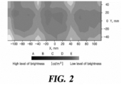
- FIG. 2 is a view showing the result of a simulation of the brightness of an image according to the related art.
- an apparatus for generating pictures for a head-up display includes: a printed circuit board (PCB) including a plurality of light sources; a liquid crystal display (LCD) disposed in front of the plurality of light sources and forming display images based on light emitted from the plurality of light sources; a funnel reflector including an internal optical surface including a double funnel structure and disposed between the PCB and the LCD to guide the light to the LCD; a housing including a space for accommodating the funnel reflector and including, on an upper surface thereof, an LCD seat for accommodating the LCD and a diffuser seat formed at the same angle as the LCD seat; and a diffuser accommodated in the diffuser seat, wherein the funnel reflector includes a tapered top surface and the top surface is formed at an angle corresponding to an angle of the diffuser seat to maintain a uniform distance from the diffuser.
- PCB printed circuit board
- LCD liquid crystal display
- the overall uniformity of light emitted to the LCD may be enhanced.
- FIG. 4 is a perspective view of the apparatus for generating pictures for a head-up display according to an embodiment of the present disclosure.
- the housing 330 may include an LCD seat for accommodating the LCD 350.
- the housing 330 may include a diffuser seat for accommodating the diffuser 340.
- the LCD seat and the diffuser seat may be formed on a top surface of the housing 330 at the same angle. Accordingly, the diffuser 340 may be contiguous to the LCD 350.
- the diffuser seat may be formed on the top surface of the housing 330.
- the top surface of the housing 330 may be inclined at a predetermined angle.
- the diffuser seat may be formed in a stepped shape to have a space in which the diffuser 340 can be seated.
- the diffuser seat may include a coupling groove into which a portion of the diffuser 340 can be fitted. The shape of the coupling groove may vary depending on the shape of the diffuser 340.
- the LCD 350 may be disposed in front of the plurality of light sources 312.
- the LCD 350 may form a display image based on light emitted from the plurality of light sources 312.
- FIG. 5 is a top plan view of the funnel reflector according to an embodiment of the present disclosure.
- the support unit 520 may include the through hole 526.
- a plurality of through holes 526 may be included.
- the through hole 526 may allow the funnel reflector 320 to be fastened to some or all of the heat sink 300, the PCB 310, and the housing 330 by use of bolts.
- the through holes 526 for the heat sink 300, the PCB 310, and the housing 330 may be at the same positions as those on the funnel reflector 320.
- a first imaginary surface 600 refers to an imaginary surface parallel to the diffuser 340 inclined at an angle.
- a third imaginary surface 610 refers to an imaginary surface parallel to an upper face of the heat sink 300.
- the first imaginary surface 600 and the second imaginary surface 620 may form the same angle with respect to the third imaginary surface 610. That is, the first imaginary surface 600 and the second imaginary surface 620 are parallel to each other.
- the diffuser 340 may be inclined at the same angle as the upper face 510 of the funnel reflector.
- the diffuser 340 and the upper face 510 of the funnel reflector may be spaced apart from each other by a predetermined distance.
- a leakage phenomenon may be prevented by having the upper face 510 of the funnel reflector and the LCD 350 disposed parallel to each other.
- the internal optical surface 730 may have an internal reflection structure which is a two-layer structure.
- the light source side is referred to as a first layer
- the LCD 350 side is referred to as a second layer.
- the funnel reflector 320 may include the first funnel 710 on the first layer and the second funnel 720 on the second layer.
- a plurality of the first funnels 710 may be included.
- the second funnel 720 is a single structure including all of the plurality of first funnels 710.
- the plurality of first funnels 710 may include a first funnel light reflection structure 732, a first funnel input-side opening 740, and a first funnel output-side opening 750.
- the first funnel light reflection structure 732 may refer to an optical surface from the first funnel input-side opening 740 to the first funnel output-side opening 750. Accordingly, a curved surface of the first funnel light reflection structure 732 may be formed based on a curved shape from the first funnel input-side opening 740 to the first funnel output-side opening 750.
- the shapes of the first and second funnels 710 and 720 may be designed by taking into consideration the pattern in which light is emitted from the light source 312 in use and the surface reflection properties of inner surfaces of the first and second funnels 710 and 720. For example, their shapes may be designed to provide a range of light diffusion angles, light homogeneity in the image area of the LCD 350, etc. required for the apparatus for generating pictures 30 by using computational simulation such as a Monte-Carlo optical ray-tracing method.
- the 3D light pattern in the Lambertian radiation form from the light source 312 may be specularly and diffusely reflected by the reflective surface of the first funnel light reflection structure 732, which is a convex curved surface, the shape of a cross section of light having a uniform intensity in the first funnel output-side opening 750 may change from a circular shape to a rectangular shape.
- the specular reflection may determine the overall light pattern, and the diffuse reflection may contribute to averaging of the intensity of light by spreading the reflected light.
- first and second funnels 710 and 720 may be of various shapes depending on a pattern in which light is emitted from the light source 312 and the surface reflection properties by the first and second funnels 710 and 720, and may be optimized through computational simulation.
- the snap latch 726 may protrude toward the rear of the funnel reflector 320 so that the funnel reflector 320 may be coupled to the PCB 310.
- the PCB 310 may be coupled to the rear of the funnel reflector 320 by the coupling force of the snap latch 726.
- the size of the display used for the simulation showing the distribution of the brightness of the image is 200 mm in width and 80 mm in length, which is the same size as the display in FIG. 2 .
Landscapes
- Physics & Mathematics (AREA)
- Nonlinear Science (AREA)
- General Physics & Mathematics (AREA)
- Optics & Photonics (AREA)
- Engineering & Computer Science (AREA)
- Chemical & Material Sciences (AREA)
- Mathematical Physics (AREA)
- Crystallography & Structural Chemistry (AREA)
- Mechanical Engineering (AREA)
- Transportation (AREA)
- Combustion & Propulsion (AREA)
- Computer Hardware Design (AREA)
- Theoretical Computer Science (AREA)
- Human Computer Interaction (AREA)
- General Engineering & Computer Science (AREA)
- Planar Illumination Modules (AREA)
- Devices For Indicating Variable Information By Combining Individual Elements (AREA)
- Instrument Panels (AREA)
Abstract
Description
- This application claims the benefit of and priority to
Korean Patent Application No. 10-2022-0187661, filed on December 28, 2022 - The present disclosure relates to an apparatus for generating pictures for a head-up display.
- The contents described in the present section are only to provide background information for the present disclosure and are not to describe the related art.
- A head-up display is a device for displaying driving information, which has been developed for a driver's safe driving. Driving information is formed in the form of an image in an apparatus for generating pictures and passes through an optical system. The driving information passed through the optical system is projected onto a windshield of a vehicle or a translucent reflective screen disposed inside a vehicle to be provided to a driver. An apparatus for generating pictures includes a liquid crystal display (LCD) that forms an image and a back light unit (BLU) disposed at the rear of the LCD to project the image to an optical system inside a head-up display. Here, the BLU includes a diffuser, a housing funnel, a printed circuit board (PCB), and a heat sink.
- The head-up display needs to be capable of providing an image recognizable to a driver even in a daylight environment in the front of a vehicle. An image formed on the LCD is enlarged while passing through an optical system and then projected onto a windshield of a vehicle or a translucent reflective screen. The brightness of the final projected light image becomes lower than that of a light image on the LCD. Therefore, compared to general displays, an apparatus for generating pictures for a head-up display needs to provide a very large and uniform quantity of light.
-
FIG. 1A is a perspective view of a housing funnel according to the related art.FIG. 1B is a top plan view of the housing funnel according to the related art. - Referring to
FIG. 1A and FIG. 1B , the housing funnel according to the related art may include anLCD seat 100, adiffuser seat 110, and an internaloptical surface 120. Here, the internaloptical surface 120 may include afirst funnel 122 and asecond funnel 124. - The
LCD seat 100 may accommodate an LCD. TheLCD seat 100 may be inclined at an angle and formed on an upper surface of the housing funnel. - The
diffuser seat 110 may accommodate a diffuser. The difference between the angle of a surface of thediffuser seat 110 and the angle of a surface of theLCD seat 100 may correspond to the angle of theLCD seat 100 with respect to the angle of thediffuser seat 110. Therefore, when light emitted from a light source is emitted onto the LCD via the diffuser, the light may be refracted by the difference between the angle of the diffuser and the angle of the LCD, resulting in a low uniformity of the light. -
FIG. 2 is a view showing the result of a simulation of the brightness of an image according to the related art. - Referring to
FIG. 1A, FIG. 1B andFIG. 2 , the size of the display used for the simulation showing the distribution of the brightness of the image is 200 mm in width and 80 mm in length. A distribution of brightness is shown on the display for the simulation according to brightness of the light source. Areas with high brightness have a color close to black, and areas with low brightness have a color close to white. Here, the unit of the brightness of the image is cd/m 2, and the level of the brightness of the image is classified into grades A to E. The high brightness of the image is classified as grade A, and the low brightness of the image is classified as grade E. - According to the result of the simulation of the brightness of the image according to the related art, due to the shape of the outermost edge of the internal
optical surface 120 and the light reflection structures of thefirst funnel 122 and thesecond funnel 124, the brightness at the outermost edge of the image on the display is rapidly reduced, and the overall uniformity of light is lowered. - In an apparatus for generating pictures for a head-up display according to an embodiment of the present disclosure, the brightness of light emitted to an outermost edge of an LCD may be improved.
- In the apparatus for generating pictures for a head-up display according to an embodiment of the present disclosure, the overall uniformity of light emitted to the LCD may be enhanced.
- Problems to be solved by the present disclosure are not limited to the above-mentioned problems, and the following description will allow a person having ordinary skill in the art to clearly understand other problems not mentioned above.
- According to an embodiment of the present disclosure, an apparatus for generating pictures for a head-up display includes: a printed circuit board (PCB) including a plurality of light sources; a liquid crystal display (LCD) disposed in front of the plurality of light sources and forming display images based on light emitted from the plurality of light sources; a funnel reflector including an internal optical surface including a double funnel structure and disposed between the PCB and the LCD to guide the light to the LCD; a housing including a space for accommodating the funnel reflector and including, on an upper surface thereof, an LCD seat for accommodating the LCD and a diffuser seat formed at the same angle as the LCD seat; and a diffuser accommodated in the diffuser seat, wherein the funnel reflector includes a tapered top surface and the top surface is formed at an angle corresponding to an angle of the diffuser seat to maintain a uniform distance from the diffuser.
- In the apparatus for generating pictures for a head-up display according to an embodiment of the present disclosure, the brightness of light emitted to the outermost edge of the LCD may be improved.
- In the apparatus for generating pictures for a head-up display according to an embodiment of the present disclosure, the overall uniformity of light emitted to the LCD may be enhanced.
-
-
FIG. 1A is a perspective view of a housing funnel according to the related art. -
FIG. 1B is a top plan view of the housing funnel according to the related art. -
FIG. 2 is a view showing the result of a simulation of the brightness of an image according to the related art. -
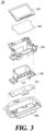
FIG. 3 is an exploded perspective view of an apparatus for generating pictures for a head-up display according to an embodiment of the present disclosure. -
FIG. 4 is a perspective view of the apparatus for generating pictures for a head-up display according to an embodiment of the present disclosure. -
FIG. 5 is a top plan view of a funnel reflector according to an embodiment of the present disclosure. -
FIG. 6 is a cross-sectional view taken along the line A-A' ofFIG. 4 . -
FIG. 7 is a cross-sectional view taken along the line B-B' ofFIG. 5 . -
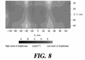
FIG. 8 is a view showing the result of a simulation of the brightness of an image according to an embodiment of the present disclosure. - Hereinafter, some exemplary embodiments of the present disclosure will be described in detail with reference to the accompanying drawings. In the following description, like reference numerals preferably designate like elements, although the elements are shown in different drawings. Furthermore, in the following description of some embodiments, a detailed description of known functions and configurations incorporated therein will be omitted for the purpose of clarity and for brevity.
- Additionally, various terms such as first, second, A, B, (a), (b), etc., are used solely to differentiate one component from the other but not to imply or suggest the substances, order, or sequence of the components. Throughout the present specification, when a part 'includes' or 'comprises' a component, the part is meant to further include other components, not to exclude thereof unless specifically stated to the contrary.
- In describing components in the embodiments according to the present disclosure, referring to a front, rear, etc. direction is only to indicate the position and direction in which a certain component is combined with other components, and the nature, order, etc. of the component is not limited by the direction. In describing components in the embodiments according to the present disclosure, when something is described as being at the front or in a front direction, it means that it is located above a certain component, for example, on an "upper part," "upper end," and the like, and, when something is described as being at the rear or in a rear direction, it means that it is located below a certain component, for example, on a "lower part," "lower end," and the like.
-
FIG. 3 is an exploded perspective view of an apparatus for generating pictures for a head-up display according to an embodiment of the present disclosure. -
FIG. 4 is a perspective view of the apparatus for generating pictures for a head-up display according to an embodiment of the present disclosure. - Referring to
FIG. 3 andFIG. 4 , the apparatus for generatingpictures 30 may include all or some of aheat sink 300, a printed circuit board (PCB) 310, alight source 312, afunnel reflector 320, ahousing 330, adiffuser 340, and a liquid crystal display (LCD) 350. - The
heat sink 300 may be disposed at the rearmost of the apparatus for generatingpictures 30. Theheat sink 300 may dissipate heat generated inside the apparatus for generatingpictures 30 to the outside. - The
PCB 310 may include thelight source 312. A plurality oflight sources 312 may be included. The plurality oflight sources 312 may be formed on one surface of thePCB 310. The plurality oflight sources 312 may be formed on thePCB 310 in a predetermined arrangement pattern. Here, thelight source 312 may be a light emitting diode (LED). - The
funnel reflector 320 may be disposed between thePCB 310 and theLCD 350. - The
funnel reflector 320 may have a double funnel structure to guide light emitted from the plurality oflight sources 312 to theLCD 350. - The
housing 330 may include a space for accommodating thefunnel reflector 320. Thehousing 330 may be disposed in front of thefunnel reflector 320. - The
housing 330 may include an LCD seat for accommodating theLCD 350. In addition, thehousing 330 may include a diffuser seat for accommodating thediffuser 340. The LCD seat and the diffuser seat may be formed on a top surface of thehousing 330 at the same angle. Accordingly, thediffuser 340 may be contiguous to theLCD 350. - The
LCD 350 may be fixed to the LCD seat using a plurality of latches formed on the top surface of the housing. Here, latches formed on at least one surface among the plurality of latches may have elasticity so that theLCD 350 may be easily coupled thereto. - The diffuser seat may be formed on the top surface of the
housing 330. The top surface of thehousing 330 may be inclined at a predetermined angle. The diffuser seat may be formed in a stepped shape to have a space in which thediffuser 340 can be seated. The diffuser seat may include a coupling groove into which a portion of thediffuser 340 can be fitted. The shape of the coupling groove may vary depending on the shape of thediffuser 340. - The
LCD 350 may be disposed in front of the plurality oflight sources 312. TheLCD 350 may form a display image based on light emitted from the plurality oflight sources 312. -
FIG. 5 is a top plan view of the funnel reflector according to an embodiment of the present disclosure. - Referring to
FIG. 5 , thefunnel reflector 320 may include all or some of asupport unit 520,first coupling protrusions hole 526, and asnap latch 530. - The
funnel reflector 320 may include itsupper face 510. Theupper face 510 of the funnel reflector may be a tapered surface. The taper angle of theupper face 510 of the funnel reflector may correspond to the angle of the diffuser seat. Specifically, when thefunnel reflector 320 is accommodated in the space formed inside thehousing 330, theupper face 510 of the funnel reflector may be parallel to the surface of the diffuser seat and spaced apart therefrom by a predetermined distance. - The inner surface of the
funnel reflector 320 may be formed as an optical surface. Anoutermost edge 512 of the optical surface may be filleted to be a curved surface. In the case of the filletedoutermost edge 512, when light is emitted from the plurality oflight sources 312 to theLCD 350, the brightness of the light emitted to an outermost edge of theLCD 350 may be improved. Here, theoutermost edge 512 may include four edges. - The
support unit 520 may extend outwardly on both sides of thefunnel reflector 320 in a longitudinal direction. Thesupport unit 520 may include thefirst coupling protrusions hole 526. Thefirst coupling protrusions first coupling protrusions first coupling protrusions housing 330 in a longitudinal direction, respectively. The long hole and short hole may be formed to allow assembly tolerance between thefunnel reflector 320 and thehousing 330. - The
support unit 520 may include the throughhole 526. A plurality of throughholes 526 may be included. The throughhole 526 may allow thefunnel reflector 320 to be fastened to some or all of theheat sink 300, thePCB 310, and thehousing 330 by use of bolts. The throughholes 526 for theheat sink 300, thePCB 310, and thehousing 330 may be at the same positions as those on thefunnel reflector 320. -
FIG. 6 is a cross-sectional view taken along the line A-A' ofFIG. 4 . - Referring to
FIG. 6 , when thediffuser 340 is seated on the diffuser seat, thediffuser 340 may be inclined at a predetermined angle based on the angle of the diffuser seat. Here, a firstimaginary surface 600 refers to an imaginary surface parallel to thediffuser 340 inclined at an angle. - A second
imaginary surface 620 refers to an imaginary surface parallel to theupper face 510 of the funnel reflector. - A third
imaginary surface 610 refers to an imaginary surface parallel to an upper face of theheat sink 300. - The first
imaginary surface 600 and the secondimaginary surface 620 may form the same angle with respect to the thirdimaginary surface 610. That is, the firstimaginary surface 600 and the secondimaginary surface 620 are parallel to each other. Thediffuser 340 may be inclined at the same angle as theupper face 510 of the funnel reflector. Thediffuser 340 and theupper face 510 of the funnel reflector may be spaced apart from each other by a predetermined distance. - When light is emitted from the
light source 312 to theLCD 350 via thefunnel reflector 320, a leakage phenomenon may be prevented by having theupper face 510 of the funnel reflector and theLCD 350 disposed parallel to each other. -
FIG. 7 is a cross-sectional view taken along the line B-B' ofFIG. 5 . - Referring to
FIG. 7 , thefunnel reflector 320 may include all or some of afirst funnel 710, asecond funnel 720,second coupling protrusions optical surface 730. - The internal
optical surface 730 may have an internal reflection structure which is a two-layer structure. For convenience of description, the light source side is referred to as a first layer, and theLCD 350 side is referred to as a second layer. Thefunnel reflector 320 according to an embodiment of the present disclosure may include thefirst funnel 710 on the first layer and thesecond funnel 720 on the second layer. Here, a plurality of thefirst funnels 710 may be included. Thesecond funnel 720 is a single structure including all of the plurality offirst funnels 710. - The plurality of
first funnels 710 may include a first funnel light reflection structure 732, a first funnel input-side opening 740, and a first funnel output-side opening 750. The first funnel light reflection structure 732 may refer to an optical surface from the first funnel input-side opening 740 to the first funnel output-side opening 750. Accordingly, a curved surface of the first funnel light reflection structure 732 may be formed based on a curved shape from the first funnel input-side opening 740 to the first funnel output-side opening 750. - Each of the first funnel input-
side openings 740 is formed to correspond to each of the plurality oflight sources 312 disposed on thePCB 310. Each of the first funnel input-side openings 740 is formed to be larger than its correspondinglight source 312. The center of the first funnel input-side opening 740 may overlap the center of thelight source 312. The output specifications of thelight sources 312 and the number and arrangement of thelight sources 312 disposed on thePCB 310 may be selected by taking into consideration the amount of light required for the apparatus for generatingpictures 30, the size of theLCD 350, etc. - When viewed as a whole, the shape formed by the outer edges of a plurality of first funnel output-
side openings 750 may correspond to the second funnel input-side opening. That is, the shape formed by the outer edges of the plurality of first funnel output-side openings 750 may be continuously in contact with the second funnel input-side opening. - A second funnel output-side opening may be formed to correspond to the image area of the
LCD 350. An outermost edge of the second funnel output-side opening may be theoutermost edge 512 of the internaloptical surface 730. - The internal
optical surface 730 of a double funnel structure including the first andsecond funnels light sources 312 to thesecond funnel 720 through thefirst funnel 710. The light from the plurality of the light sources passed through the plurality offirst funnels 710 may be mixed with each other in thesecond funnel 720, pass through thediffuser 340 and then be incident on the rear of theLCD 350. - As described above, the shapes of the first and
second funnels light source 312 in use and the surface reflection properties of inner surfaces of the first andsecond funnels LCD 350, etc. required for the apparatus for generatingpictures 30 by using computational simulation such as a Monte-Carlo optical ray-tracing method. The shapes may be designed to enable diffusely reflected light and specularly reflected light to be mixed while the light emitted from the plurality of LED light sources passes through the first andsecond funnels LCD 350 in the form of a flat light having a rectangular cross section similar to theLCD 350 and having a uniform light intensity. - According to an embodiment of the present disclosure, the first funnel light reflection structure 732 may be formed in a curved shape, e.g., a free curved shape having multiple radii.
- Specifically, the first funnel light reflection structure 732 may be formed based on the positions of the plurality of
light sources 312. When thefunnel reflector 320 is disposed in front of thePCB 310, the plurality oflight sources 312 may be located inside the first funnel input-side opening 740. When the plurality oflight sources 312 are disposed in each of a plurality of first funnel input-side openings 740, thelight source 312 may be located at the center of the first funnel input-side opening 740. However, even when the positions of the plurality oflight sources 312 on thePCB 310 are different and they are not located at the center of the first funnel input-side opening 740, light may be uniformly emitted toward theLCD 350 based on the free curved shape of the first funnel light reflection structure 732. - The internal
optical surface 730 may be sanded. Then, by the internaloptical surface 730, the uniformity of light emitted to theLCD 350 may be improved. In addition, sensitivity to tolerances between parts of the apparatus for generatingpictures 30 may be reduced by the internaloptical surface 730. Here, the sanding may be a process of flattening protruding portions on the surface of a product by spraying fine sand, etc. together with high-pressure compressed air. - The internal
optical surface 730 may be coated with aluminum. Here, the coating of aluminum may be applied by physical vapor deposition such as sputtering, an electron beam, filtered cathodic vacuum arc, thermal evaporation, and an ion beam and various types of chemical vapor deposition including plasma enhanced chemical vapor deposition. Since the internaloptical surface 730 may be coated with aluminum, uniformity of thickness and color of the coating layer may be secured. - The most basic first and
second funnels LCD 350. - However, a cross section of light from the
light source 312 perpendicular to the traveling direction of the light may not maintain a rectangular shape in the light path from the first funnel input-side opening 740 to the second funnel output-side opening. This is because, even when thelight source 312 has a rectangular shape, the light radiated therefrom may be radiated in all directions of 360 degrees from each local light starting point and thus be in the Lambertian radiation form as described above. - The Lambertian radiation form may have a Gaussian distribution in which the intensity of a cross section of light is highest along the central axis of the light and decreases toward the periphery. For example, the radiation form of light may have a distribution where 90 % of the luminous intensity is concentrated in the range of ±20 degrees based on a primary optical axis toward the front of the light source and 50 % of the luminous intensity is included in the range of ±60 degrees. A 3D distribution of the intensity of light with respect to a front area of the
light source 312 may vary depending on a light source used. - According to another embodiment of the present disclosure, the shape of a cross section of the first and
second funnels second funnels LCD 350. - Although not shown, for example, the first funnel input-
side opening 740 may basically have a rectangular shape, but may have a curved shape with each side concave toward the center of the rectangular shape. In other words, a cross section of the first funnel input-side opening 740 may have a shape in which four concave curved lines are arranged in a rectangular shape, with a central portion close to the central optical axis of a light source. - The first funnel output-
side opening 750 may have a similar shape. However, each side of the first funnel output-side opening 750 may be less concave than each side of the first funnel input-side opening 740. Here, a reflective surface of the first funnel light reflection structure 732 connecting the first funnel input-side opening 740 and the first funnel output-side opening 750 may not be a flat surface but a curved surface convex toward the central axis of thefirst funnel 710. - In this case, since the 3D light pattern in the Lambertian radiation form from the
light source 312 may be specularly and diffusely reflected by the reflective surface of the first funnel light reflection structure 732, which is a convex curved surface, the shape of a cross section of light having a uniform intensity in the first funnel output-side opening 750 may change from a circular shape to a rectangular shape. Among surface reflection properties, the specular reflection may determine the overall light pattern, and the diffuse reflection may contribute to averaging of the intensity of light by spreading the reflected light. - The input-side opening of the
second funnel 720 may correspond to the shape formed by the plurality of first funnel output-side openings 750, and the output-side opening of thesecond funnel 720 may correspond to the shape of theLCD 350. A reflective surface of the light reflection structure of the second funnel may be concave so that light incident on theLCD 350 is substantially perpendicular to the rear surface of theLCD 350. - The above-described embodiment is merely illustrative, and the detailed structures of the first and
second funnels light source 312 and the surface reflection properties by the first andsecond funnels - In summary, when it comes to securing the uniformity of a light pattern, superposing a plurality of light patterns with rectangular cross sections may be more desirable than forming a single uniform rectangular light pattern by superposing a plurality of light patterns with circular cross sections. Therefore, since a pattern of a cross section of light may turn into a rectangular shape by the plurality of
first funnels 710 having such a modified cross section shape, it may be possible that the uniformity of light intensity of a plurality of light patterns mixed in thesecond funnel 720 is more easily secured. - Referring to
FIG. 5 , the internaloptical surface 730 may include the filletedoutermost edge 512. - Based on the technical characteristics of the internal
optical surface 730, in thefunnel reflector 320, the brightness of light radiated to theLCD 350 may be 16,186 cd/m 2 or more, for example, 17,594 cd/m 2. In addition, the overall uniformity of light radiated to theLCD 350 may be 72 % or more, for example, 76.2 %. - The
second coupling protrusions support unit 520. Thesecond coupling protrusions funnel reflector 320 may be coupled to thePCB 310 and theheat sink 300. Thesecond coupling protrusions - A plurality of the snap latches 726 may be included. The snap latches 726 may be respectively disposed at lower ends of both sides of the
funnel reflector 320 in a lateral or width direction. - The snap latch 726 may protrude toward the rear of the
funnel reflector 320 so that thefunnel reflector 320 may be coupled to thePCB 310. ThePCB 310 may be coupled to the rear of thefunnel reflector 320 by the coupling force of the snap latch 726. -
FIG. 8 is a view showing the result of a simulation of the brightness of an image according to an embodiment of the present disclosure. - Referring to
FIG. 5 to FIG. 8 , the size of the display used for the simulation showing the distribution of the brightness of the image is 200 mm in width and 80 mm in length, which is the same size as the display inFIG. 2 . - It can be seen that, compared to the distribution of the brightness of an image according to the related art disclosed in
FIG. 2 , the brightness of the outermost edge is improved in the distribution of the brightness of the image according to an embodiment of the present disclosure. In other words, the color of the outermost edge on the display is close to a dark color, i.e., a color corresponding to grade A. This indicates that it may be possible to enhance the brightness and overall uniformity of an image based on the technical characteristics of thefunnel reflector 320 according to an embodiment of the present disclosure. Specifically, by filleting theoutermost edge 512 of thefunnel reflector 320, light reflected in the internaloptical surface 730 may be uniformly radiated even to the outermost edge of theLCD 350. In addition, it may be possible to improve the overall uniformity of light radiated to theLCD 350 based on the free curved shape of the first funnel light reflection structure 732. - Although exemplary embodiments of the present disclosure have been described for illustrative purposes, those skilled in the art will appreciate that various modifications, additions, and substitutions are possible, without departing from the idea and scope of the claimed invention. Therefore, exemplary embodiments of the present disclosure have been described for the sake of brevity and clarity. The scope of the technical idea of the present embodiments is not limited by the illustrations. Accordingly, one of ordinary skill would understand that the scope of the claimed invention is not to be limited by the above explicitly described embodiments but by the claims and equivalents thereof.
Claims (8)
- An apparatus for generating pictures for a head-up display, the apparatus comprising:a printed circuit board (PCB) including a plurality of light sources configured to emit light;a liquid crystal display (LCD) disposed in front of the plurality of light sources and configured to form a display image based on the light emitted from the plurality of light sources;a funnel reflector including an internal optical surface having a double funnel structure and disposed between the PCB and the LCD to guide the light toward the LCD;a housing having a space at which the funnel reflector is disposed and including (1) an upper surface, (2) an LCD seat disposed on the upper surface of the housing and accommodating the LCD and (3) a diffuser seat disposed at a same angle as the LCD seat on the upper surface of the housing; anda diffuser accommodated at the diffuser seat,wherein the funnel reflector includes a tapered top surface disposed at an angle corresponding to that of the diffuser seat to maintain a uniform distance from the diffuser.
- The apparatus of claim 1, wherein:the double funnel structure includes (1) a plurality of first funnels respectively corresponding to the plurality of light sources and (2) a second funnel disposed in front of the plurality of first funnels,each of the plurality of first funnels includes a first funnel input-side opening, a first funnel output-side opening having a cross section larger than that of the first funnel input-side opening, and a first funnel light reflection structure interconnecting the first funnel input-side opening and the first funnel output-side opening, andthe first funnel light reflection structure has a curved shape.
- The apparatus of claim 1 or 2, wherein the internal optical surface includes a sanded surface.
- The apparatus of any one of claims 1 to 3, wherein the internal optical surface has an aluminum-coated surface.
- The apparatus of any one of claims 1 to 4, wherein an outermost edge of the internal optical surface has a curved surface.
- The apparatus of any one of claims 1 to 5, wherein the funnel reflector includes a plurality of snap latches respectively disposed at lower ends of both sides of the funnel reflector in a lateral direction and coupled to the PCB.
- The apparatus of any one of claims 1 to 6, wherein the funnel reflector includes a plurality of support units respectively extending in a longitudinal direction of the funnel reflector outside the internal optical surface and configured to fix the funnel reflector in the apparatus.
- The apparatus of claim 7, wherein each of the plurality of support units includes:a plurality of coupling protrusions protruding in forward and backward directions of the plurality of support units; anda plurality of through holes.
Applications Claiming Priority (1)
| Application Number | Priority Date | Filing Date | Title |
|---|---|---|---|
| KR1020220187661A KR102851639B1 (en) | 2022-12-28 | 2022-12-28 | Picture Generating Apparatus for use in Head-Up Display |
Publications (2)
| Publication Number | Publication Date |
|---|---|
| EP4393744A1 true EP4393744A1 (en) | 2024-07-03 |
| EP4393744B1 EP4393744B1 (en) | 2025-10-22 |
Family
ID=85792283
Family Applications (1)
| Application Number | Title | Priority Date | Filing Date |
|---|---|---|---|
| EP23165468.2A Active EP4393744B1 (en) | 2022-12-28 | 2023-03-30 | Picture generating apparatus for use in head-up display |
Country Status (4)
| Country | Link |
|---|---|
| US (1) | US11982807B1 (en) |
| EP (1) | EP4393744B1 (en) |
| KR (1) | KR102851639B1 (en) |
| CN (1) | CN118259462A (en) |
Citations (5)
| Publication number | Priority date | Publication date | Assignee | Title |
|---|---|---|---|---|
| US20040062040A1 (en) * | 2002-09-27 | 2004-04-01 | Heinrich-Jochen Blume | Device for producing an image |
| US20190094620A1 (en) * | 2017-09-27 | 2019-03-28 | Japan Display Inc. | Display device and head-up display device |
| CN113504651A (en) * | 2021-07-19 | 2021-10-15 | 昆山金运新材料科技有限公司 | Surface collimation light conversion mechanism and HUD light source module adopting same |
| US20220043258A1 (en) * | 2020-08-10 | 2022-02-10 | Hyundai Mobis Co., Ltd. | Picture generation unit for head-up display |
| US11347102B2 (en) * | 2018-09-04 | 2022-05-31 | Japan Display Inc. | Display device |
Family Cites Families (8)
| Publication number | Priority date | Publication date | Assignee | Title |
|---|---|---|---|---|
| JP3075134B2 (en) * | 1995-04-04 | 2000-08-07 | 株式会社日立製作所 | Reflective liquid crystal display |
| US6320759B1 (en) * | 1997-08-22 | 2001-11-20 | Adc Dsl Systems, Inc. | Printed circuit board adapter |
| US7619825B1 (en) * | 2004-09-27 | 2009-11-17 | Rockwell Collins, Inc. | Compact head up display with wide viewing angle |
| KR20150137723A (en) * | 2014-05-30 | 2015-12-09 | 엘지이노텍 주식회사 | Head-Up display |
| JP2018084596A (en) * | 2016-11-21 | 2018-05-31 | マクセル株式会社 | Information display device |
| EP3615981A1 (en) * | 2017-03-03 | 2020-03-04 | Ostendo Technologies, Inc. | Split exit pupil heads-up display systems and methods |
| KR102803870B1 (en) * | 2020-08-10 | 2025-05-02 | 현대모비스 주식회사 | Picture Generating Apparatus for Use in Head-Up Display |
| JP7534255B2 (en) * | 2021-03-29 | 2024-08-14 | マクセル株式会社 | Light source device and electronic device |
-
2022
- 2022-12-28 KR KR1020220187661A patent/KR102851639B1/en active Active
-
2023
- 2023-02-28 US US18/175,691 patent/US11982807B1/en active Active
- 2023-03-30 EP EP23165468.2A patent/EP4393744B1/en active Active
- 2023-04-07 CN CN202310369094.9A patent/CN118259462A/en active Pending
Patent Citations (5)
| Publication number | Priority date | Publication date | Assignee | Title |
|---|---|---|---|---|
| US20040062040A1 (en) * | 2002-09-27 | 2004-04-01 | Heinrich-Jochen Blume | Device for producing an image |
| US20190094620A1 (en) * | 2017-09-27 | 2019-03-28 | Japan Display Inc. | Display device and head-up display device |
| US11347102B2 (en) * | 2018-09-04 | 2022-05-31 | Japan Display Inc. | Display device |
| US20220043258A1 (en) * | 2020-08-10 | 2022-02-10 | Hyundai Mobis Co., Ltd. | Picture generation unit for head-up display |
| CN113504651A (en) * | 2021-07-19 | 2021-10-15 | 昆山金运新材料科技有限公司 | Surface collimation light conversion mechanism and HUD light source module adopting same |
Also Published As
| Publication number | Publication date |
|---|---|
| KR20240104932A (en) | 2024-07-05 |
| KR102851639B1 (en) | 2025-08-27 |
| US11982807B1 (en) | 2024-05-14 |
| EP4393744B1 (en) | 2025-10-22 |
| CN118259462A (en) | 2024-06-28 |
Similar Documents
| Publication | Publication Date | Title |
|---|---|---|
| US5673128A (en) | Back light device of liquid crystal device | |
| CN100529520C (en) | Backlight unit having light guide buffer plate | |
| KR100769066B1 (en) | Back-lighting unit and liquid crystal display using the same | |
| CN100410768C (en) | Backlight system and liquid crystal display using the backlight system | |
| EP2581641A1 (en) | Planar light source device and illumination apparatus | |
| US20080170412A1 (en) | Spread illuminating apparatus | |
| USRE45749E1 (en) | Optical unit, backlight assembly having the same and display device having the same | |
| US8272774B2 (en) | Light guiding plate, and backlight assembly and display device having the same | |
| CN102112802A (en) | Light source device, lighting device, and display device | |
| US11592666B2 (en) | Picture generation unit for head-up display | |
| US20080158880A1 (en) | Planar light source apparatus, display apparatus and planar illumination method | |
| US11022842B2 (en) | Planar light source device and display device | |
| CN116137886B (en) | Backlight module and display device | |
| US20010050816A1 (en) | Spread illuminating apparatus | |
| EP1892563A1 (en) | Surface light source device, backlight unit and liquid crystal display having the same | |
| US11982807B1 (en) | Picture generating apparatus comprising a funnel reflector having a double funnel structure for use in a head-up display | |
| EP2762959B1 (en) | Display device | |
| KR102803870B1 (en) | Picture Generating Apparatus for Use in Head-Up Display | |
| JP6796746B1 (en) | Planar lighting device | |
| TWI722799B (en) | Surface light source apparatus and liquid crystal display device | |
| JP2003123526A (en) | Surface light source homogenizer | |
| CN118696200A (en) | Optical component, light source device and head-up display | |
| JP7174920B2 (en) | Display device | |
| JP3981836B2 (en) | LCD panel lighting device | |
| CN101821547A (en) | Backlight unit and liquid crystal display device |
Legal Events
| Date | Code | Title | Description |
|---|---|---|---|
| PUAI | Public reference made under article 153(3) epc to a published international application that has entered the european phase |
Free format text: ORIGINAL CODE: 0009012 |
|
| STAA | Information on the status of an ep patent application or granted ep patent |
Free format text: STATUS: REQUEST FOR EXAMINATION WAS MADE |
|
| 17P | Request for examination filed |
Effective date: 20230330 |
|
| AK | Designated contracting states |
Kind code of ref document: A1 Designated state(s): AL AT BE BG CH CY CZ DE DK EE ES FI FR GB GR HR HU IE IS IT LI LT LU LV MC ME MK MT NL NO PL PT RO RS SE SI SK SM TR |
|
| STAA | Information on the status of an ep patent application or granted ep patent |
Free format text: STATUS: EXAMINATION IS IN PROGRESS |
|
| 17Q | First examination report despatched |
Effective date: 20250113 |
|
| GRAP | Despatch of communication of intention to grant a patent |
Free format text: ORIGINAL CODE: EPIDOSNIGR1 |
|
| STAA | Information on the status of an ep patent application or granted ep patent |
Free format text: STATUS: GRANT OF PATENT IS INTENDED |
|
| INTG | Intention to grant announced |
Effective date: 20250715 |
|
| RIN1 | Information on inventor provided before grant (corrected) |
Inventor name: SHIN, MIN HO |
|
| GRAS | Grant fee paid |
Free format text: ORIGINAL CODE: EPIDOSNIGR3 |
|
| GRAA | (expected) grant |
Free format text: ORIGINAL CODE: 0009210 |
|
| STAA | Information on the status of an ep patent application or granted ep patent |
Free format text: STATUS: THE PATENT HAS BEEN GRANTED |
|
| AK | Designated contracting states |
Kind code of ref document: B1 Designated state(s): AL AT BE BG CH CY CZ DE DK EE ES FI FR GB GR HR HU IE IS IT LI LT LU LV MC ME MK MT NL NO PL PT RO RS SE SI SK SM TR |
|
| REG | Reference to a national code |
Ref country code: CH Ref legal event code: F10 Free format text: ST27 STATUS EVENT CODE: U-0-0-F10-F00 (AS PROVIDED BY THE NATIONAL OFFICE) Effective date: 20251022 Ref country code: GB Ref legal event code: FG4D |
|
| REG | Reference to a national code |
Ref country code: DE Ref legal event code: R096 Ref document number: 602023007664 Country of ref document: DE |
|
| REG | Reference to a national code |
Ref country code: IE Ref legal event code: FG4D |
|
| REG | Reference to a national code |
Ref country code: NL Ref legal event code: MP Effective date: 20251022 |
|
| PG25 | Lapsed in a contracting state [announced via postgrant information from national office to epo] |
Ref country code: NL Free format text: LAPSE BECAUSE OF FAILURE TO SUBMIT A TRANSLATION OF THE DESCRIPTION OR TO PAY THE FEE WITHIN THE PRESCRIBED TIME-LIMIT Effective date: 20251022 |
|
| PG25 | Lapsed in a contracting state [announced via postgrant information from national office to epo] |
Ref country code: ES Free format text: LAPSE BECAUSE OF FAILURE TO SUBMIT A TRANSLATION OF THE DESCRIPTION OR TO PAY THE FEE WITHIN THE PRESCRIBED TIME-LIMIT Effective date: 20251022 |
|
| REG | Reference to a national code |
Ref country code: LT Ref legal event code: MG9D |
|
| PG25 | Lapsed in a contracting state [announced via postgrant information from national office to epo] |
Ref country code: NO Free format text: LAPSE BECAUSE OF FAILURE TO SUBMIT A TRANSLATION OF THE DESCRIPTION OR TO PAY THE FEE WITHIN THE PRESCRIBED TIME-LIMIT Effective date: 20260122 |
|
| PGFP | Annual fee paid to national office [announced via postgrant information from national office to epo] |
Ref country code: DE Payment date: 20260323 Year of fee payment: 4 |
|
| PG25 | Lapsed in a contracting state [announced via postgrant information from national office to epo] |
Ref country code: FI Free format text: LAPSE BECAUSE OF FAILURE TO SUBMIT A TRANSLATION OF THE DESCRIPTION OR TO PAY THE FEE WITHIN THE PRESCRIBED TIME-LIMIT Effective date: 20251022 Ref country code: HR Free format text: LAPSE BECAUSE OF FAILURE TO SUBMIT A TRANSLATION OF THE DESCRIPTION OR TO PAY THE FEE WITHIN THE PRESCRIBED TIME-LIMIT Effective date: 20251022 Ref country code: AT Free format text: LAPSE BECAUSE OF FAILURE TO SUBMIT A TRANSLATION OF THE DESCRIPTION OR TO PAY THE FEE WITHIN THE PRESCRIBED TIME-LIMIT Effective date: 20251022 |
|
| PGFP | Annual fee paid to national office [announced via postgrant information from national office to epo] |
Ref country code: AT Payment date: 20260301 Year of fee payment: 4 |
|
| REG | Reference to a national code |
Ref country code: AT Ref legal event code: MK05 Ref document number: 1848867 Country of ref document: AT Kind code of ref document: T Effective date: 20251022 |
|
| PG25 | Lapsed in a contracting state [announced via postgrant information from national office to epo] |
Ref country code: RS Free format text: LAPSE BECAUSE OF FAILURE TO SUBMIT A TRANSLATION OF THE DESCRIPTION OR TO PAY THE FEE WITHIN THE PRESCRIBED TIME-LIMIT Effective date: 20260122 |
|
| PG25 | Lapsed in a contracting state [announced via postgrant information from national office to epo] |
Ref country code: IS Free format text: LAPSE BECAUSE OF FAILURE TO SUBMIT A TRANSLATION OF THE DESCRIPTION OR TO PAY THE FEE WITHIN THE PRESCRIBED TIME-LIMIT Effective date: 20260222 |
|
| PGFP | Annual fee paid to national office [announced via postgrant information from national office to epo] |
Ref country code: FR Payment date: 20260323 Year of fee payment: 4 |
|
| PG25 | Lapsed in a contracting state [announced via postgrant information from national office to epo] |
Ref country code: PT Free format text: LAPSE BECAUSE OF FAILURE TO SUBMIT A TRANSLATION OF THE DESCRIPTION OR TO PAY THE FEE WITHIN THE PRESCRIBED TIME-LIMIT Effective date: 20260223 |
|
| PG25 | Lapsed in a contracting state [announced via postgrant information from national office to epo] |
Ref country code: PL Free format text: LAPSE BECAUSE OF FAILURE TO SUBMIT A TRANSLATION OF THE DESCRIPTION OR TO PAY THE FEE WITHIN THE PRESCRIBED TIME-LIMIT Effective date: 20251022 |
|
| PG25 | Lapsed in a contracting state [announced via postgrant information from national office to epo] |
Ref country code: LV Free format text: LAPSE BECAUSE OF FAILURE TO SUBMIT A TRANSLATION OF THE DESCRIPTION OR TO PAY THE FEE WITHIN THE PRESCRIBED TIME-LIMIT Effective date: 20251022 |
|
| PG25 | Lapsed in a contracting state [announced via postgrant information from national office to epo] |
Ref country code: BG Free format text: LAPSE BECAUSE OF FAILURE TO SUBMIT A TRANSLATION OF THE DESCRIPTION OR TO PAY THE FEE WITHIN THE PRESCRIBED TIME-LIMIT Effective date: 20251022 |
|
| PG25 | Lapsed in a contracting state [announced via postgrant information from national office to epo] |
Ref country code: LT Free format text: LAPSE BECAUSE OF FAILURE TO SUBMIT A TRANSLATION OF THE DESCRIPTION OR TO PAY THE FEE WITHIN THE PRESCRIBED TIME-LIMIT Effective date: 20251022 |
|
| PG25 | Lapsed in a contracting state [announced via postgrant information from national office to epo] |
Ref country code: SM Free format text: LAPSE BECAUSE OF FAILURE TO SUBMIT A TRANSLATION OF THE DESCRIPTION OR TO PAY THE FEE WITHIN THE PRESCRIBED TIME-LIMIT Effective date: 20251022 |
|
| PG25 | Lapsed in a contracting state [announced via postgrant information from national office to epo] |
Ref country code: DK Free format text: LAPSE BECAUSE OF FAILURE TO SUBMIT A TRANSLATION OF THE DESCRIPTION OR TO PAY THE FEE WITHIN THE PRESCRIBED TIME-LIMIT Effective date: 20251022 |
|
| PG25 | Lapsed in a contracting state [announced via postgrant information from national office to epo] |
Ref country code: IT Free format text: LAPSE BECAUSE OF FAILURE TO SUBMIT A TRANSLATION OF THE DESCRIPTION OR TO PAY THE FEE WITHIN THE PRESCRIBED TIME-LIMIT Effective date: 20251022 |
|
| PG25 | Lapsed in a contracting state [announced via postgrant information from national office to epo] |
Ref country code: EE Free format text: LAPSE BECAUSE OF FAILURE TO SUBMIT A TRANSLATION OF THE DESCRIPTION OR TO PAY THE FEE WITHIN THE PRESCRIBED TIME-LIMIT Effective date: 20251022 |
|
| PG25 | Lapsed in a contracting state [announced via postgrant information from national office to epo] |
Ref country code: CZ Free format text: LAPSE BECAUSE OF FAILURE TO SUBMIT A TRANSLATION OF THE DESCRIPTION OR TO PAY THE FEE WITHIN THE PRESCRIBED TIME-LIMIT Effective date: 20251022 |
|
| PG25 | Lapsed in a contracting state [announced via postgrant information from national office to epo] |
Ref country code: SK Free format text: LAPSE BECAUSE OF FAILURE TO SUBMIT A TRANSLATION OF THE DESCRIPTION OR TO PAY THE FEE WITHIN THE PRESCRIBED TIME-LIMIT Effective date: 20251022 |
|
| PG25 | Lapsed in a contracting state [announced via postgrant information from national office to epo] |
Ref country code: SE Free format text: LAPSE BECAUSE OF FAILURE TO SUBMIT A TRANSLATION OF THE DESCRIPTION OR TO PAY THE FEE WITHIN THE PRESCRIBED TIME-LIMIT Effective date: 20251022 |