EP4393680A1 - Truss additive manufacturing device for aerospace - Google Patents
Truss additive manufacturing device for aerospace Download PDFInfo
- Publication number
- EP4393680A1 EP4393680A1 EP23866614.3A EP23866614A EP4393680A1 EP 4393680 A1 EP4393680 A1 EP 4393680A1 EP 23866614 A EP23866614 A EP 23866614A EP 4393680 A1 EP4393680 A1 EP 4393680A1
- Authority
- EP
- European Patent Office
- Prior art keywords
- truss
- aerospace
- additive manufacturing
- wheel
- manufacturing device
- Prior art date
- Legal status (The legal status is an assumption and is not a legal conclusion. Google has not performed a legal analysis and makes no representation as to the accuracy of the status listed.)
- Granted
Links
Images

Classifications
-
- B—PERFORMING OPERATIONS; TRANSPORTING
- B29—WORKING OF PLASTICS; WORKING OF SUBSTANCES IN A PLASTIC STATE IN GENERAL
- B29C—SHAPING OR JOINING OF PLASTICS; SHAPING OF MATERIAL IN A PLASTIC STATE, NOT OTHERWISE PROVIDED FOR; AFTER-TREATMENT OF THE SHAPED PRODUCTS, e.g. REPAIRING
- B29C64/00—Additive manufacturing, i.e. manufacturing of three-dimensional [3D] objects by additive deposition, additive agglomeration or additive layering, e.g. by 3D printing, stereolithography or selective laser sintering
- B29C64/20—Apparatus for additive manufacturing; Details thereof or accessories therefor
- B29C64/205—Means for applying layers
- B29C64/218—Rollers
-
- B—PERFORMING OPERATIONS; TRANSPORTING
- B33—ADDITIVE MANUFACTURING TECHNOLOGY
- B33Y—ADDITIVE MANUFACTURING, i.e. MANUFACTURING OF THREE-DIMENSIONAL [3D] OBJECTS BY ADDITIVE DEPOSITION, ADDITIVE AGGLOMERATION OR ADDITIVE LAYERING, e.g. BY 3D PRINTING, STEREOLITHOGRAPHY OR SELECTIVE LASER SINTERING
- B33Y10/00—Processes of additive manufacturing
-
- B—PERFORMING OPERATIONS; TRANSPORTING
- B29—WORKING OF PLASTICS; WORKING OF SUBSTANCES IN A PLASTIC STATE IN GENERAL
- B29C—SHAPING OR JOINING OF PLASTICS; SHAPING OF MATERIAL IN A PLASTIC STATE, NOT OTHERWISE PROVIDED FOR; AFTER-TREATMENT OF THE SHAPED PRODUCTS, e.g. REPAIRING
- B29C64/00—Additive manufacturing, i.e. manufacturing of three-dimensional [3D] objects by additive deposition, additive agglomeration or additive layering, e.g. by 3D printing, stereolithography or selective laser sintering
- B29C64/10—Processes of additive manufacturing
- B29C64/171—Processes of additive manufacturing specially adapted for manufacturing multiple 3D objects
-
- B—PERFORMING OPERATIONS; TRANSPORTING
- B29—WORKING OF PLASTICS; WORKING OF SUBSTANCES IN A PLASTIC STATE IN GENERAL
- B29C—SHAPING OR JOINING OF PLASTICS; SHAPING OF MATERIAL IN A PLASTIC STATE, NOT OTHERWISE PROVIDED FOR; AFTER-TREATMENT OF THE SHAPED PRODUCTS, e.g. REPAIRING
- B29C64/00—Additive manufacturing, i.e. manufacturing of three-dimensional [3D] objects by additive deposition, additive agglomeration or additive layering, e.g. by 3D printing, stereolithography or selective laser sintering
- B29C64/20—Apparatus for additive manufacturing; Details thereof or accessories therefor
-
- B—PERFORMING OPERATIONS; TRANSPORTING
- B29—WORKING OF PLASTICS; WORKING OF SUBSTANCES IN A PLASTIC STATE IN GENERAL
- B29C—SHAPING OR JOINING OF PLASTICS; SHAPING OF MATERIAL IN A PLASTIC STATE, NOT OTHERWISE PROVIDED FOR; AFTER-TREATMENT OF THE SHAPED PRODUCTS, e.g. REPAIRING
- B29C64/00—Additive manufacturing, i.e. manufacturing of three-dimensional [3D] objects by additive deposition, additive agglomeration or additive layering, e.g. by 3D printing, stereolithography or selective laser sintering
- B29C64/20—Apparatus for additive manufacturing; Details thereof or accessories therefor
- B29C64/227—Driving means
-
- B—PERFORMING OPERATIONS; TRANSPORTING
- B29—WORKING OF PLASTICS; WORKING OF SUBSTANCES IN A PLASTIC STATE IN GENERAL
- B29C—SHAPING OR JOINING OF PLASTICS; SHAPING OF MATERIAL IN A PLASTIC STATE, NOT OTHERWISE PROVIDED FOR; AFTER-TREATMENT OF THE SHAPED PRODUCTS, e.g. REPAIRING
- B29C64/00—Additive manufacturing, i.e. manufacturing of three-dimensional [3D] objects by additive deposition, additive agglomeration or additive layering, e.g. by 3D printing, stereolithography or selective laser sintering
- B29C64/20—Apparatus for additive manufacturing; Details thereof or accessories therefor
- B29C64/227—Driving means
- B29C64/236—Driving means for motion in a direction within the plane of a layer
-
- B—PERFORMING OPERATIONS; TRANSPORTING
- B29—WORKING OF PLASTICS; WORKING OF SUBSTANCES IN A PLASTIC STATE IN GENERAL
- B29C—SHAPING OR JOINING OF PLASTICS; SHAPING OF MATERIAL IN A PLASTIC STATE, NOT OTHERWISE PROVIDED FOR; AFTER-TREATMENT OF THE SHAPED PRODUCTS, e.g. REPAIRING
- B29C64/00—Additive manufacturing, i.e. manufacturing of three-dimensional [3D] objects by additive deposition, additive agglomeration or additive layering, e.g. by 3D printing, stereolithography or selective laser sintering
- B29C64/20—Apparatus for additive manufacturing; Details thereof or accessories therefor
- B29C64/295—Heating elements
-
- B—PERFORMING OPERATIONS; TRANSPORTING
- B29—WORKING OF PLASTICS; WORKING OF SUBSTANCES IN A PLASTIC STATE IN GENERAL
- B29C—SHAPING OR JOINING OF PLASTICS; SHAPING OF MATERIAL IN A PLASTIC STATE, NOT OTHERWISE PROVIDED FOR; AFTER-TREATMENT OF THE SHAPED PRODUCTS, e.g. REPAIRING
- B29C64/00—Additive manufacturing, i.e. manufacturing of three-dimensional [3D] objects by additive deposition, additive agglomeration or additive layering, e.g. by 3D printing, stereolithography or selective laser sintering
- B29C64/30—Auxiliary operations or equipment
-
- B—PERFORMING OPERATIONS; TRANSPORTING
- B29—WORKING OF PLASTICS; WORKING OF SUBSTANCES IN A PLASTIC STATE IN GENERAL
- B29C—SHAPING OR JOINING OF PLASTICS; SHAPING OF MATERIAL IN A PLASTIC STATE, NOT OTHERWISE PROVIDED FOR; AFTER-TREATMENT OF THE SHAPED PRODUCTS, e.g. REPAIRING
- B29C64/00—Additive manufacturing, i.e. manufacturing of three-dimensional [3D] objects by additive deposition, additive agglomeration or additive layering, e.g. by 3D printing, stereolithography or selective laser sintering
- B29C64/30—Auxiliary operations or equipment
- B29C64/307—Handling of material to be used in additive manufacturing
- B29C64/314—Preparation
-
- B—PERFORMING OPERATIONS; TRANSPORTING
- B29—WORKING OF PLASTICS; WORKING OF SUBSTANCES IN A PLASTIC STATE IN GENERAL
- B29C—SHAPING OR JOINING OF PLASTICS; SHAPING OF MATERIAL IN A PLASTIC STATE, NOT OTHERWISE PROVIDED FOR; AFTER-TREATMENT OF THE SHAPED PRODUCTS, e.g. REPAIRING
- B29C64/00—Additive manufacturing, i.e. manufacturing of three-dimensional [3D] objects by additive deposition, additive agglomeration or additive layering, e.g. by 3D printing, stereolithography or selective laser sintering
- B29C64/30—Auxiliary operations or equipment
- B29C64/307—Handling of material to be used in additive manufacturing
- B29C64/321—Feeding
-
- B—PERFORMING OPERATIONS; TRANSPORTING
- B29—WORKING OF PLASTICS; WORKING OF SUBSTANCES IN A PLASTIC STATE IN GENERAL
- B29C—SHAPING OR JOINING OF PLASTICS; SHAPING OF MATERIAL IN A PLASTIC STATE, NOT OTHERWISE PROVIDED FOR; AFTER-TREATMENT OF THE SHAPED PRODUCTS, e.g. REPAIRING
- B29C70/00—Shaping composites, i.e. plastics material comprising reinforcements, fillers or preformed parts, e.g. inserts
- B29C70/04—Shaping composites, i.e. plastics material comprising reinforcements, fillers or preformed parts, e.g. inserts comprising reinforcements only, e.g. self-reinforcing plastics
- B29C70/28—Shaping operations therefor
- B29C70/40—Shaping or impregnating by compression not applied
- B29C70/50—Shaping or impregnating by compression not applied for producing articles of indefinite length, e.g. prepregs, sheet moulding compounds [SMC] or cross moulding compounds [XMC]
- B29C70/504—Shaping or impregnating by compression not applied for producing articles of indefinite length, e.g. prepregs, sheet moulding compounds [SMC] or cross moulding compounds [XMC] using rollers or pressure bands
-
- B—PERFORMING OPERATIONS; TRANSPORTING
- B29—WORKING OF PLASTICS; WORKING OF SUBSTANCES IN A PLASTIC STATE IN GENERAL
- B29D—PRODUCING PARTICULAR ARTICLES FROM PLASTICS OR FROM SUBSTANCES IN A PLASTIC STATE
- B29D99/00—Subject matter not provided for in other groups of this subclass
- B29D99/0003—Producing profiled members, e.g. beams
-
- B—PERFORMING OPERATIONS; TRANSPORTING
- B33—ADDITIVE MANUFACTURING TECHNOLOGY
- B33Y—ADDITIVE MANUFACTURING, i.e. MANUFACTURING OF THREE-DIMENSIONAL [3D] OBJECTS BY ADDITIVE DEPOSITION, ADDITIVE AGGLOMERATION OR ADDITIVE LAYERING, e.g. BY 3D PRINTING, STEREOLITHOGRAPHY OR SELECTIVE LASER SINTERING
- B33Y40/00—Auxiliary operations or equipment, e.g. for material handling
-
- B—PERFORMING OPERATIONS; TRANSPORTING
- B33—ADDITIVE MANUFACTURING TECHNOLOGY
- B33Y—ADDITIVE MANUFACTURING, i.e. MANUFACTURING OF THREE-DIMENSIONAL [3D] OBJECTS BY ADDITIVE DEPOSITION, ADDITIVE AGGLOMERATION OR ADDITIVE LAYERING, e.g. BY 3D PRINTING, STEREOLITHOGRAPHY OR SELECTIVE LASER SINTERING
- B33Y40/00—Auxiliary operations or equipment, e.g. for material handling
- B33Y40/10—Pre-treatment
-
- B—PERFORMING OPERATIONS; TRANSPORTING
- B29—WORKING OF PLASTICS; WORKING OF SUBSTANCES IN A PLASTIC STATE IN GENERAL
- B29C—SHAPING OR JOINING OF PLASTICS; SHAPING OF MATERIAL IN A PLASTIC STATE, NOT OTHERWISE PROVIDED FOR; AFTER-TREATMENT OF THE SHAPED PRODUCTS, e.g. REPAIRING
- B29C64/00—Additive manufacturing, i.e. manufacturing of three-dimensional [3D] objects by additive deposition, additive agglomeration or additive layering, e.g. by 3D printing, stereolithography or selective laser sintering
- B29C64/20—Apparatus for additive manufacturing; Details thereof or accessories therefor
- B29C64/205—Means for applying layers
- B29C64/209—Heads; Nozzles
-
- B—PERFORMING OPERATIONS; TRANSPORTING
- B29—WORKING OF PLASTICS; WORKING OF SUBSTANCES IN A PLASTIC STATE IN GENERAL
- B29L—INDEXING SCHEME ASSOCIATED WITH SUBCLASS B29C, RELATING TO PARTICULAR ARTICLES
- B29L2031/00—Other particular articles
- B29L2031/30—Vehicles, e.g. ships or aircraft, or body parts thereof
- B29L2031/3097—Cosmonautical vehicles; Rockets
-
- B—PERFORMING OPERATIONS; TRANSPORTING
- B33—ADDITIVE MANUFACTURING TECHNOLOGY
- B33Y—ADDITIVE MANUFACTURING, i.e. MANUFACTURING OF THREE-DIMENSIONAL [3D] OBJECTS BY ADDITIVE DEPOSITION, ADDITIVE AGGLOMERATION OR ADDITIVE LAYERING, e.g. BY 3D PRINTING, STEREOLITHOGRAPHY OR SELECTIVE LASER SINTERING
- B33Y30/00—Apparatus for additive manufacturing; Details thereof or accessories therefor
-
- B—PERFORMING OPERATIONS; TRANSPORTING
- B33—ADDITIVE MANUFACTURING TECHNOLOGY
- B33Y—ADDITIVE MANUFACTURING, i.e. MANUFACTURING OF THREE-DIMENSIONAL [3D] OBJECTS BY ADDITIVE DEPOSITION, ADDITIVE AGGLOMERATION OR ADDITIVE LAYERING, e.g. BY 3D PRINTING, STEREOLITHOGRAPHY OR SELECTIVE LASER SINTERING
- B33Y80/00—Products made by additive manufacturing
-
- Y—GENERAL TAGGING OF NEW TECHNOLOGICAL DEVELOPMENTS; GENERAL TAGGING OF CROSS-SECTIONAL TECHNOLOGIES SPANNING OVER SEVERAL SECTIONS OF THE IPC; TECHNICAL SUBJECTS COVERED BY FORMER USPC CROSS-REFERENCE ART COLLECTIONS [XRACs] AND DIGESTS
- Y02—TECHNOLOGIES OR APPLICATIONS FOR MITIGATION OR ADAPTATION AGAINST CLIMATE CHANGE
- Y02P—CLIMATE CHANGE MITIGATION TECHNOLOGIES IN THE PRODUCTION OR PROCESSING OF GOODS
- Y02P10/00—Technologies related to metal processing
- Y02P10/25—Process efficiency
Definitions
- Truss structures formed by layering require manual preparation, with long processing cycle, poor product consistency, and inconsistent resin and fiber statuses inside trusses.
- the upper roller stores tapes for forming longitudinal beams; and the lower roller stores wires for printing a cross beam.
- a feeding portion is composed of a feeding stepper motor and conveying pressure rollers, where the feeding stepper motor drives the conveying pressure rollers to convey raw materials.
- a guide plate portion is composed of a plurality of rollers, and adjusts the direction and position of the used tapes to prepare for forming.
- the longitudinal beam forming unit includes three mold sets, which are arranged in a triangle; each mold set includes several molds, heating rods, a ceramic tube and a support plate, and is connected to the support plate through the ceramic tube; the heating rods are mounted in holes of the molds; each mold has an upper mold structure and a lower mold structure, which form a channel with a V-shaped angle; the V-shaped angle in each mold set gradually decreases from front to back; the three mold sets are arranged in a triangle and connected to the support plates through the ceramic tubes; and the pre-impregnated tapes passing through the molds form the required longitudinal beams by controlling the temperature of the molds.
- the motion module moves simultaneously, and the printing module on the motion module begins to work to print a cross beam between the two longitudinal beams.
- each mold set includes three molds; and the V-shaped angles in the mold sets are 120°, 90°, and 60°, respectively.
- the upper support frame, the left support frame and the right support frame are all made of carbon fiber boards.
- Beneficial effects of the present invention are as follows: rapid in-situ formation of composite trusses is achieved, with good forming effect and high efficiency; and the stability is improved.
Landscapes
- Engineering & Computer Science (AREA)
- Chemical & Material Sciences (AREA)
- Materials Engineering (AREA)
- Manufacturing & Machinery (AREA)
- Mechanical Engineering (AREA)
- Physics & Mathematics (AREA)
- Optics & Photonics (AREA)
- Composite Materials (AREA)
Abstract
Description
- The present invention relates to the field of additive manufacturing devices, and in particular, to an additive manufacturing device for an aerospace truss.
- At present, composite trusses are mostly manufactured by machining truss components with molds and then bonding the truss components, so the process is cumbersome and a truss structure cannot be formed once. Truss structures formed by layering require manual preparation, with long processing cycle, poor product consistency, and inconsistent resin and fiber statuses inside trusses.
- At present, technologies for forming trusses by additive manufacturing are still being developed, relevant devices are not yet mature, and there is no additive manufacturing device for an aerospace truss. The manufacturing device proposed in the present invention achieves rapid in-situ formation of composite trusses, with good forming effect and high efficiency.
- To solve the above problems, the present invention discloses an additive manufacturing device for an aerospace truss, which can efficiently complete the formation of space trusses for satellite use.
- An additive manufacturing device for an aerospace truss includes a raw material input unit, a longitudinal beam forming unit, a longitudinal beam traction unit, a cross beam forming unit and a truss support unit arranged sequentially.
- The raw material input unit includes an upper roller, a lower roller located below the upper roller, several conveying pressure rollers arranged sequentially from top to bottom, and a guide plate, where one end of the conveying pressure roller is connected to a feeding stepper motor.
- The upper roller stores tapes for forming longitudinal beams; and the lower roller stores wires for printing a cross beam. A feeding portion is composed of a feeding stepper motor and conveying pressure rollers, where the feeding stepper motor drives the conveying pressure rollers to convey raw materials. A guide plate portion is composed of a plurality of rollers, and adjusts the direction and position of the used tapes to prepare for forming.
- The longitudinal beam forming unit includes three mold sets, which are arranged in a triangle; each mold set includes several molds, heating rods, a ceramic tube and a support plate, and is connected to the support plate through the ceramic tube; the heating rods are mounted in holes of the molds; each mold has an upper mold structure and a lower mold structure, which form a channel with a V-shaped angle; the V-shaped angle in each mold set gradually decreases from front to back; the three mold sets are arranged in a triangle and connected to the support plates through the ceramic tubes; and the pre-impregnated tapes passing through the molds form the required longitudinal beams by controlling the temperature of the molds.
- The longitudinal beam traction unit includes a traction stepper motor, a coupling, a transmission shaft and an upper support frame; wing plates are distributed on two sides of the upper support frame; an angle between each wing plate and a middle plate of the upper support frame is 60°, and each wing plate has two through holes for fixing an upper power output shaft and an upper driven shaft that are arranged in parallel; the other end of the left upper power output shaft is arranged on a left support plate and connected to a bevel gear I; the other end of the right upper power output shaft is arranged on a right support plate and connected to a bevel gear II; a gear I and a concave wheel I are sequentially arranged on each upper power output shaft; a gear II and a convex wheel I that cooperate with the gear I and the concave wheel I are sequentially arranged on the upper driven shaft; the stepper motor is connected to the transmission shaft through the coupling; the transmission shaft is sequentially mounted on the left support plate and the right support plate; a bevel gear III and a bevel gear that mesh with the bevel gear I and the bevel gear II separately are sequentially arranged on the transmission shaft; a lower driven shaft parallel to the transmission shaft is mounted on the left support plate; a gear III and a convex wheel II are sequentially arranged on the lower driven shaft; the gear III and the convex wheel II cooperate with a gear IV and a concave wheel II on the transmission shaft separately; and a center line of the convex wheel II is coaxial with a center of the middle plate of the upper support frame.
- The traction stepper motor drives the transmission shaft through the coupling, so as to drive meshing between the bevel gears and the gears, enable the convex and concave rollers to move simultaneously and pull the printed truss longitudinal beams.
- The cross beam forming unit is composed of a motion module and a printing module; the truss support unit is composed of support conveying rollers and a support frame; a support conveying roller is arranged at each end of the support frame; and a shape of the support conveying rollers matches an inner surface of the truss longitudinal beam.
- Further improvement of the present invention: the printing module is arranged on a slider of the motion module; the motion module is a screw linear guide mechanism; and the printing module includes a printing assembly and a nozzle arranged on the printing assembly.
- When the longitudinal beams are formed, the motion module moves simultaneously, and the printing module on the motion module begins to work to print a cross beam between the two longitudinal beams.
- Further improvement of the present invention: three cross beam forming units are configured; and the three cross beam forming units are parallel to three sides of the truss and perpendicular to the longitudinal beams of the truss.
- Further improvement of the present invention: a gap between the concave wheel I and the convex wheel I is 0.2 mm to 3 mm; and a gap between the concave wheel II and the convex wheel II is 0.2 mm to 3 mm.
- Further improvement of the present invention: each mold set includes three molds; and the V-shaped angles in the mold sets are 120°, 90°, and 60°, respectively.
- Every two molds in each mold set are spaced by 20 mm to 40 mm. The mold has an upper mold structure and a lower mold structure in a V shape, and angles between flow channels of the molds are different, so that the 180° pre-impregnated tapes gradually transform into longitudinal beams with an angle of 60°. Taking each set of three molds as an example, the angles between the three molds are sequentially 120°, 90°, and 60° in the movement direction of the pre-impregnated tapes. A heating rod and a temperature sensor are mounted on the upper mold of each mold, and the upper and lower molds are connected by bolts.
- Further improvement of the present invention: the concave wheel I and the concave wheel II are recessed in a 60° V shape; the convex wheel I and the convex wheel II are raised in a 60° V shape; and the shapes match the structural shape of the truss.
- Further improvement of the present invention: rubber layers are arranged on surfaces of the concave wheel I and the concave wheel II, and rubber layers are arranged on surfaces of the convex wheel I and the convex wheel, to protect printed materials.
- Further improvement of the present invention: the upper support frame, the left support frame and the right support frame are all made of carbon fiber boards.
- Further improvement of the present invention: the coupling is an elastic coupling, which improves operational stability.
- Beneficial effects of the present invention are as follows: rapid in-situ formation of composite trusses is achieved, with good forming effect and high efficiency; and the stability is improved.
-
-
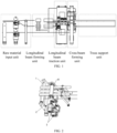
FIG. 1 is a schematic diagram of an overall design scheme of a device; -
FIG. 2 is a schematic diagram of a raw material input unit; -
FIG. 3 is a cross-sectional view of a longitudinal beam forming unit mold; -
FIG. 4 is a schematic diagram of a longitudinal beam traction unit; -
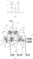
FIG. 5 is a schematic diagram of a cross beam printing and truss support unit; and -
FIG. 6 is a schematic diagram of an overall structure. - The present invention will be further illustrated below in conjunction with the accompanying drawings and specific embodiments. It should be understood that the following specific embodiments are only used for describing the present invention, rather than limiting the scope of the present invention. It should be noted that the terms "front", "back", "left", "right", "upper" and "lower" used in the following description refer to directions in the drawings, and the terms "inside" and "outside" refer to a direction toward or away from a geometric center of a specific component separately.
- As shown in
FIG. 1 , an additive manufacturing device for an aerospace truss includes a raw material input unit, a longitudinal beam forming unit, a longitudinal beam traction unit, a cross beam forming unit and a truss support unit arranged sequentially. - As shown in
FIG. 2 , the raw material input unit includes anupper roller 1, a lower roller 2 located below theupper roller 1, several conveying pressure rollers 4 arranged sequentially from top to bottom, and a guide plate. One end of the conveying pressure roller 4 is connected to a feeding stepper motor. - A storage portion of the raw material input unit is composed of brackets and rollers, two longitudinal brackets are fixed on a plane, two transverse brackets are vertically distributed in parallel and equidistantly on the longitudinal brackets, and two rollers are sheathed on the two longitudinal brackets separately. Three groove-like structures are equidistantly arranged in the two rollers in a rotation direction, upper roller grooves store pre-impregnated tapes in three directions separately, and lower roller grooves store pre-impregnated wires in three directions separately; and a feeding portion is composed of a motor, pressure rollers and brackets, where the brackets are similar to those in the storage portion, four transverse brackets are sheathed with four rollers, every rollers constitute a group and are distributed up and down, the lower roller of each group is a driving wheel, the stepper motor is connected through a coupling to achieve power input, the upper roller is a driven wheel, and the two rollers roll and transport raw materials. A meshing position of each group of rollers in the storage portion is on the same height as upper surfaces of the rollers in the storage portion. A guide portion is composed of small rollers and brackets, each small roller is on the same straight line as the storage roller groove, and the height of each small roller is determined by the longitudinal beam forming unit.
- As shown in
FIG. 3 , the longitudinal beam forming unit includes three mold sets, which are arranged in a triangle; each mold set includesseveral molds 5,heating rods 6, aceramic tube 7 and asupport plate 8, and is connected to thesupport plate 8 through theceramic tube 7; theheating rods 6 are mounted in holes of themolds 5; eachmold 5 has an upper mold structure and a lower mold structure, which form a V-shaped angle; the V-shaped angle in each mold set gradually decreases from front to back; a gap between a concave wheel 123 and a convex wheel I 25 is 0.2 mm to 3 mm; and a gap between a concave wheel II 30 and a convex wheel II 28 is 0.2 mm to 3 mm. Each mold set includes threemolds 5; the V-shaped angles in the mold sets are 120°, 90°, and 60°, respectively; the concave wheel I 23 and the concave wheel II 30 are recessed in a 60° V shape; and the convex wheel 125 and the convex wheel II 28 are raised in a 60° V shape. - Angles between flow channels of the molds are different, so that the 180° pre-impregnated tapes passing through the molds gradually transform into required longitudinal beams with an angle of 60°.
- As shown in
FIG. 4 , the longitudinal beam traction unit includes atraction stepper motor 15, acoupling 10, a transmission shaft 9 and anupper support frame 16; wing plates 16-1 are distributed on two sides of theupper support frame 16; an angle between each wing plate 16-1 and a middle plate of theupper support frame 16 is 60°, and each wing plate 16-1 has two through holes for fixing an upperpower output shaft 17 and an upper drivenshaft 18 that are arranged in parallel; the other end of the left upperpower output shaft 17 is arranged on aleft support plate 19 and connected to a bevel gear I 11; the other end of the right upperpower output shaft 17 is arranged on aright support plate 20 and connected to a bevel gear II 21; a gear I 12 and the concave wheel I 23 are sequentially arranged on each upperpower output shaft 17; a gear II 24 and the convex wheel I 25 that cooperate with the gear I 12 and theconcave wheel I 23 are sequentially arranged on the upper drivenshaft 18; thestepper motor 15 is connected to the transmission shaft 9 through thecoupling 10; the transmission shaft 9 is sequentially mounted on theleft support plate 19 and theright support plate 20; a bevel gear III 26 and abevel gear 31 that mesh with the bevel gear I 11 and the bevel gear II 21 separately are sequentially arranged on the transmission shaft 9; a lower drivenshaft 26 parallel to the transmission shaft 9 is mounted on theleft support plate 19; a gear III 27 and the convex wheel II 28 are sequentially arranged on the lower drivenshaft 26; the gear III 27 and the convex wheel II 28 cooperate with a gear IV 29 and a concave wheel II 30 on the transmission shaft 9 separately; and a center line of the convex wheel II 28 is coaxial with a center of the middle plate of theupper support frame 16. - The stepper motor in the longitudinal beam traction unit is connected to one of the transmission shafts through the coupling, and the transmission shafts are driven by the bevel gears, so that the stepper motor drives the driven shafts to move. Spur gears on the transmission shafts drive the gears on the driven shafts, so that convex and concave rollers move simultaneously to pull printed truss longitudinal beams.
- The cross beam forming unit is composed of a motion module and a printing module; the truss support unit is composed of
support conveying rollers 50 and a support frame 51; asupport conveying roller 50 is arranged at each end of the support frame 51; and a shape of thesupport conveying rollers 50 matches an inner surface of the truss longitudinal beam. The printing module is arranged on a slider of themotion module 40; themotion module 40 is a screw linear guide mechanism; and the printing module includes aprinting assembly 41 and anozzle 42 arranged on theprinting assembly 41. - The motion module of the cross beam forming unit is fixed to the device through a bracket, and is parallel to three sides of the truss. When the longitudinal beams are formed, the motion module moves simultaneously, and the printing module on the motion module works to print a cross beam between the two longitudinal beams.
- The technical means disclosed in the solution of the present invention are not limited to the technical means disclosed in the foregoing implementations, and further include technical solutions constituted by any combination of the above technical features.
Claims (9)
- An additive manufacturing device for an aerospace truss, comprising a raw material input unit, a longitudinal beam forming unit, a longitudinal beam traction unit, a cross beam forming unit and a truss support unit arranged sequentially, whereinthe raw material input unit comprises an upper roller (1), a lower roller (2) located below the upper roller (1), several conveying pressure rollers (4) arranged sequentially from top to bottom, and a guide plate; one end of the conveying pressure roller (4) is connected to a feeding stepper motor;the longitudinal beam forming unit comprises three mold sets, which are arranged in a triangle; each mold set comprises several molds (5), heating rods (6), a ceramic tube (7) and a support plate (8), and is connected to the support plate (8) through the ceramic tube (7); the heating rods (6) are mounted in holes of the molds (5); each mold (5) has an upper mold structure and a lower mold structure, which form a V-shaped angle; the V-shaped angle in each mold set gradually decreases from front to back; andthe longitudinal beam traction unit comprises a traction stepper motor (15), a coupling (10), a transmission shaft (9) and an upper support frame (16); wing plates (16-1) are distributed on two sides of the upper support frame (16); an angle between each wing plate (16-1) and a middle plate of the upper support frame (16) is 60°, and each wing plate (16-1) has two through holes for fixing an upper power output shaft (17) and an upper driven shaft (18) that are arranged in parallel; the other end of the left upper power output shaft (17) is arranged on a left support plate (19) and connected to a bevel gear I (11); the other end of the right upper power output shaft (17) is arranged on a right support plate (20) and connected to a bevel gear II (21); a gear I (12) and a concave wheel I (23) are sequentially arranged on each upper power output shaft (17); a gear II (24) and a convex wheel I (25) that cooperate with the gear I (12) and the concave wheel I (23) are sequentially arranged on the upper driven shaft (18); the stepper motor (15) is connected to the transmission shaft (9) through the coupling (10); the transmission shaft (9) is sequentially mounted on the left support plate (19) and the right support plate (20); a bevel gear III (26) and a bevel gear (31) that mesh with the bevel gear I (11) and the bevel gear II (21) separately are sequentially arranged on the transmission shaft (9); a lower driven shaft (26) parallel to the transmission shaft (9) is mounted on the left support plate (19); a gear III (27) and a convex wheel II (28) are sequentially arranged on the lower driven shaft (26); the gear III (27) and the convex wheel II (28) cooperate with a gear IV (29) and a concave wheel II (30) on the transmission shaft (9) separately; a center line of the convex wheel II (28) is coaxial with a center of the middle plate of the upper support frame (16); the cross beam forming unit is composed of a motion module and a printing module; the truss support unit is composed of support conveying rollers (50) and a support frame (51); a support conveying roller (50) is arranged at each end of the support frame (51); and a shape of the support conveying rollers (50) matches an inner surface of a truss longitudinal beam.
- The additive manufacturing device for an aerospace truss according to claim 1, wherein the printing module is arranged on a slider of the motion module (40); the motion module (40) is a screw linear guide mechanism; and the printing module comprises a printing assembly (41) and a nozzle (42) arranged on the printing assembly (41).
- The additive manufacturing device for an aerospace truss according to claim 1, wherein three cross beam forming units are configured; and the three cross beam forming units are parallel to three sides of the truss and perpendicular to the longitudinal beams of the truss.
- The additive manufacturing device for an aerospace truss according to claim 1, wherein
a gap between the concave wheel I (23) and the convex wheel I (25) is 0.2 mm to 3 mm; and a gap between the concave wheel II (30) and the convex wheel II (28) is 0.2 mm to 3 mm. - The additive manufacturing device for an aerospace truss according to claim 1, wherein
each mold set comprises three molds (5); and the V-shaped angles in the mold sets are 120°, 90°, and 60°, respectively. - The additive manufacturing device for an aerospace truss according to claim 1, wherein
the concave wheel I (23) and the concave wheel II (30) are recessed in a 60° V shape; and the convex wheel I (25) and the convex wheel II (28) are raised in a 60° V shape. - The additive manufacturing device for an aerospace truss according to claim 1, wherein
rubber layers are arranged on surfaces of the concave wheel I (23) and the concave wheel II (30); and rubber layers are arranged on surfaces of the convex wheel I (25) and the convex wheel II (28). - The additive manufacturing device for an aerospace truss according to claim 1, wherein the upper support frame, the left support frame and the right support frame are all made of carbon fiber boards.
- The additive manufacturing device for an aerospace truss according to claim 1, wherein the coupling (9) is an elastic coupling.
Applications Claiming Priority (2)
| Application Number | Priority Date | Filing Date | Title |
|---|---|---|---|
| CN202211334837.0A CN115742295B (en) | 2022-10-28 | 2022-10-28 | Truss additive manufacturing device for aerospace |
| PCT/CN2023/077080 WO2024087420A1 (en) | 2022-10-28 | 2023-02-20 | Truss additive manufacturing device for aerospace |
Publications (4)
| Publication Number | Publication Date |
|---|---|
| EP4393680A1 true EP4393680A1 (en) | 2024-07-03 |
| EP4393680A4 EP4393680A4 (en) | 2024-10-30 |
| EP4393680B1 EP4393680B1 (en) | 2025-08-13 |
| EP4393680B8 EP4393680B8 (en) | 2025-10-22 |
Family
ID=90014684
Family Applications (1)
| Application Number | Title | Priority Date | Filing Date |
|---|---|---|---|
| EP23866614.3A Active EP4393680B8 (en) | 2022-10-28 | 2023-02-20 | Truss additive manufacturing device for aerospace |
Country Status (2)
| Country | Link |
|---|---|
| US (1) | US11911961B1 (en) |
| EP (1) | EP4393680B8 (en) |
Families Citing this family (1)
| Publication number | Priority date | Publication date | Assignee | Title |
|---|---|---|---|---|
| CN119017734B (en) * | 2024-10-12 | 2025-09-12 | 南京航空航天大学 | A method for forming a spatial three-dimensional truss |
Family Cites Families (8)
| Publication number | Priority date | Publication date | Assignee | Title |
|---|---|---|---|---|
| MXPA03000732A (en) * | 2000-07-28 | 2003-07-14 | Univ Brigham Young | Iso-truss structure. |
| NZ739456A (en) * | 2015-08-03 | 2021-12-24 | Redwire Space Inc | In-space manufacturing and assembly of spacecraft device and techniques |
| US20180250850A1 (en) | 2016-06-01 | 2018-09-06 | Apis Cor Engineering, Llc | Composite material for 3d printing produced by pultrusion method |
| US11220049B2 (en) | 2019-10-29 | 2022-01-11 | Saudi Arabian Oil Company | System and method for three-dimensional printing of fiber reinforced thermoplastics with multi-axial reinforcement |
| US11693390B2 (en) | 2020-05-07 | 2023-07-04 | Technion Research & Development Foundation Limited | Systems and methods for generation of a truss |
| WO2022060504A2 (en) * | 2020-08-14 | 2022-03-24 | Arris Composites Inc. | Method for composite truss manufacturing |
| CN113263723B (en) * | 2021-04-30 | 2022-04-05 | 西安交通大学 | Variable radius multi-print head integrated truss 3D printer and method of use |
| US12269617B2 (en) * | 2022-04-06 | 2025-04-08 | Maxar Space Llc | 3D printed spacecraft structures |
-
2023
- 2023-02-20 EP EP23866614.3A patent/EP4393680B8/en active Active
- 2023-09-06 US US18/242,529 patent/US11911961B1/en active Active
Also Published As
| Publication number | Publication date |
|---|---|
| US11911961B1 (en) | 2024-02-27 |
| EP4393680B8 (en) | 2025-10-22 |
| EP4393680A4 (en) | 2024-10-30 |
| EP4393680B1 (en) | 2025-08-13 |
Similar Documents
| Publication | Publication Date | Title |
|---|---|---|
| CN115742295B (en) | Truss additive manufacturing device for aerospace | |
| US11897805B2 (en) | Forming apparatus for curved tempered glass, and forming method | |
| US11911961B1 (en) | Additive manufacturing device for aerospace truss | |
| CN107244079A (en) | A kind of integrated laying device of carbon fiber | |
| CN114013068A (en) | Annular wire laying machine tool and wire laying method thereof | |
| CN114407351B (en) | Continuous fiber hybrid reinforced thermoplastic matrix composite material additive manufacturing equipment | |
| CN117087205A (en) | An aerospace truss winding forming device | |
| CN216635473U (en) | Annular wire laying machine tool | |
| CN115431515A (en) | A five-axis 3D printer for continuous fiber composite materials with wire cutting function | |
| CN219748973U (en) | Long fiber thermoplastic composite material linkage impregnating equipment | |
| CN218663641U (en) | Automatic feeding mechanism for machining | |
| CN214395426U (en) | Double-nozzle 3D printing device | |
| CN206170672U (en) | Glass steel pultrusion fixed length cutting machine | |
| CN217837550U (en) | Online sheet storage system equipment for glass storage | |
| CN110712363B (en) | A modular six-axis robotic arm pellet extrusion molding device | |
| CN210732577U (en) | Coiled material class material cutting mechanism | |
| CN222346340U (en) | A pultrusion equipment | |
| CN223864396U (en) | Double-spindle mirror image horizontal automatic laying device | |
| CN221315070U (en) | Cutting device is used in plastic panel production | |
| CN119858337A (en) | Hot pressing device for carbon fiber pultrusion plate | |
| CN221453867U (en) | Servo sideslip device of extrusion rod | |
| CN112706515A (en) | Paper tube off-line printing machine with pattern shaping structure and working method thereof | |
| CN219466774U (en) | Plate forming machine | |
| CN215248341U (en) | Paper feeding mechanism of cladding machine | |
| CN223533042U (en) | A UV-curable inner lining tubing thickness adjustment extrusion device |
Legal Events
| Date | Code | Title | Description |
|---|---|---|---|
| STAA | Information on the status of an ep patent application or granted ep patent |
Free format text: STATUS: UNKNOWN |
|
| STAA | Information on the status of an ep patent application or granted ep patent |
Free format text: STATUS: THE INTERNATIONAL PUBLICATION HAS BEEN MADE |
|
| PUAI | Public reference made under article 153(3) epc to a published international application that has entered the european phase |
Free format text: ORIGINAL CODE: 0009012 |
|
| STAA | Information on the status of an ep patent application or granted ep patent |
Free format text: STATUS: REQUEST FOR EXAMINATION WAS MADE |
|
| 17P | Request for examination filed |
Effective date: 20240326 |
|
| AK | Designated contracting states |
Kind code of ref document: A1 Designated state(s): AL AT BE BG CH CY CZ DE DK EE ES FI FR GB GR HR HU IE IS IT LI LT LU LV MC ME MK MT NL NO PL PT RO RS SE SI SK SM TR |
|
| A4 | Supplementary search report drawn up and despatched |
Effective date: 20241002 |
|
| RIC1 | Information provided on ipc code assigned before grant |
Ipc: B33Y 10/00 20150101ALI20240926BHEP Ipc: B29C 64/171 20170101AFI20240926BHEP |
|
| GRAP | Despatch of communication of intention to grant a patent |
Free format text: ORIGINAL CODE: EPIDOSNIGR1 |
|
| STAA | Information on the status of an ep patent application or granted ep patent |
Free format text: STATUS: GRANT OF PATENT IS INTENDED |
|
| DAV | Request for validation of the european patent (deleted) | ||
| DAX | Request for extension of the european patent (deleted) | ||
| INTG | Intention to grant announced |
Effective date: 20250507 |
|
| RIC1 | Information provided on ipc code assigned before grant |
Ipc: B33Y 30/00 20150101ALI20250428BHEP Ipc: B29D 99/00 20100101ALI20250428BHEP Ipc: B29C 70/50 20060101ALI20250428BHEP Ipc: B33Y 40/10 20200101ALI20250428BHEP Ipc: B33Y 40/00 20200101ALI20250428BHEP Ipc: B33Y 10/00 20150101ALI20250428BHEP Ipc: B29C 64/321 20170101ALI20250428BHEP Ipc: B29C 64/314 20170101ALI20250428BHEP Ipc: B29C 64/30 20170101ALI20250428BHEP Ipc: B29C 64/295 20170101ALI20250428BHEP Ipc: B29C 64/227 20170101ALI20250428BHEP Ipc: B29C 64/20 20170101ALI20250428BHEP Ipc: B29C 64/171 20170101AFI20250428BHEP |
|
| GRAS | Grant fee paid |
Free format text: ORIGINAL CODE: EPIDOSNIGR3 |
|
| GRAA | (expected) grant |
Free format text: ORIGINAL CODE: 0009210 |
|
| STAA | Information on the status of an ep patent application or granted ep patent |
Free format text: STATUS: THE PATENT HAS BEEN GRANTED |
|
| AK | Designated contracting states |
Kind code of ref document: B1 Designated state(s): AL AT BE BG CH CY CZ DE DK EE ES FI FR GB GR HR HU IE IS IT LI LT LU LV MC ME MK MT NL NO PL PT RO RS SE SI SK SM TR |
|
| REG | Reference to a national code |
Ref country code: GB Ref legal event code: FG4D |
|
| REG | Reference to a national code |
Ref country code: CH Ref legal event code: EP |
|
| REG | Reference to a national code |
Ref country code: DE Ref legal event code: R096 Ref document number: 602023005758 Country of ref document: DE |
|
| GRAT | Correction requested after decision to grant or after decision to maintain patent in amended form |
Free format text: ORIGINAL CODE: EPIDOSNCDEC |
|
| REG | Reference to a national code |
Ref country code: IE Ref legal event code: FG4D |
|
| REG | Reference to a national code |
Ref country code: CH Ref legal event code: PK Free format text: BERICHTIGUNGEN |
|
| REG | Reference to a national code |
Ref country code: CH Ref legal event code: PK Free format text: BERICHTIGUNG B8 |
|
| RIN2 | Information on inventor provided after grant (corrected) |
Inventor name: ZHENG, JINGHUA Inventor name: CHEN, YIWEI Inventor name: SHAN, ZHONGDE Inventor name: FAN, CONGZE Inventor name: SONG, WENZHE Inventor name: LIU, KAI |
|
| REG | Reference to a national code |
Ref country code: NL Ref legal event code: MP Effective date: 20250813 |
|
| PG25 | Lapsed in a contracting state [announced via postgrant information from national office to epo] |
Ref country code: IS Free format text: LAPSE BECAUSE OF FAILURE TO SUBMIT A TRANSLATION OF THE DESCRIPTION OR TO PAY THE FEE WITHIN THE PRESCRIBED TIME-LIMIT Effective date: 20251213 |
|
| PG25 | Lapsed in a contracting state [announced via postgrant information from national office to epo] |
Ref country code: NO Free format text: LAPSE BECAUSE OF FAILURE TO SUBMIT A TRANSLATION OF THE DESCRIPTION OR TO PAY THE FEE WITHIN THE PRESCRIBED TIME-LIMIT Effective date: 20251113 |
|
| REG | Reference to a national code |
Ref country code: LT Ref legal event code: MG9D |
|
| PG25 | Lapsed in a contracting state [announced via postgrant information from national office to epo] |
Ref country code: PT Free format text: LAPSE BECAUSE OF FAILURE TO SUBMIT A TRANSLATION OF THE DESCRIPTION OR TO PAY THE FEE WITHIN THE PRESCRIBED TIME-LIMIT Effective date: 20251215 |
|
| PG25 | Lapsed in a contracting state [announced via postgrant information from national office to epo] |
Ref country code: FI Free format text: LAPSE BECAUSE OF FAILURE TO SUBMIT A TRANSLATION OF THE DESCRIPTION OR TO PAY THE FEE WITHIN THE PRESCRIBED TIME-LIMIT Effective date: 20250813 |
|
| PG25 | Lapsed in a contracting state [announced via postgrant information from national office to epo] |
Ref country code: HR Free format text: LAPSE BECAUSE OF FAILURE TO SUBMIT A TRANSLATION OF THE DESCRIPTION OR TO PAY THE FEE WITHIN THE PRESCRIBED TIME-LIMIT Effective date: 20250813 Ref country code: NL Free format text: LAPSE BECAUSE OF FAILURE TO SUBMIT A TRANSLATION OF THE DESCRIPTION OR TO PAY THE FEE WITHIN THE PRESCRIBED TIME-LIMIT Effective date: 20250813 |
|
| PG25 | Lapsed in a contracting state [announced via postgrant information from national office to epo] |
Ref country code: GR Free format text: LAPSE BECAUSE OF FAILURE TO SUBMIT A TRANSLATION OF THE DESCRIPTION OR TO PAY THE FEE WITHIN THE PRESCRIBED TIME-LIMIT Effective date: 20251114 |
|
| PG25 | Lapsed in a contracting state [announced via postgrant information from national office to epo] |
Ref country code: SE Free format text: LAPSE BECAUSE OF FAILURE TO SUBMIT A TRANSLATION OF THE DESCRIPTION OR TO PAY THE FEE WITHIN THE PRESCRIBED TIME-LIMIT Effective date: 20250813 |
|
| PG25 | Lapsed in a contracting state [announced via postgrant information from national office to epo] |
Ref country code: LV Free format text: LAPSE BECAUSE OF FAILURE TO SUBMIT A TRANSLATION OF THE DESCRIPTION OR TO PAY THE FEE WITHIN THE PRESCRIBED TIME-LIMIT Effective date: 20250813 |
|
| PG25 | Lapsed in a contracting state [announced via postgrant information from national office to epo] |
Ref country code: PL Free format text: LAPSE BECAUSE OF FAILURE TO SUBMIT A TRANSLATION OF THE DESCRIPTION OR TO PAY THE FEE WITHIN THE PRESCRIBED TIME-LIMIT Effective date: 20250813 Ref country code: BG Free format text: LAPSE BECAUSE OF FAILURE TO SUBMIT A TRANSLATION OF THE DESCRIPTION OR TO PAY THE FEE WITHIN THE PRESCRIBED TIME-LIMIT Effective date: 20250813 |
|
| PG25 | Lapsed in a contracting state [announced via postgrant information from national office to epo] |
Ref country code: RS Free format text: LAPSE BECAUSE OF FAILURE TO SUBMIT A TRANSLATION OF THE DESCRIPTION OR TO PAY THE FEE WITHIN THE PRESCRIBED TIME-LIMIT Effective date: 20251113 |
|
| PG25 | Lapsed in a contracting state [announced via postgrant information from national office to epo] |
Ref country code: ES Free format text: LAPSE BECAUSE OF FAILURE TO SUBMIT A TRANSLATION OF THE DESCRIPTION OR TO PAY THE FEE WITHIN THE PRESCRIBED TIME-LIMIT Effective date: 20250813 |
|
| REG | Reference to a national code |
Ref country code: AT Ref legal event code: MK05 Ref document number: 1824249 Country of ref document: AT Kind code of ref document: T Effective date: 20250813 |
|
| PG25 | Lapsed in a contracting state [announced via postgrant information from national office to epo] |
Ref country code: SM Free format text: LAPSE BECAUSE OF FAILURE TO SUBMIT A TRANSLATION OF THE DESCRIPTION OR TO PAY THE FEE WITHIN THE PRESCRIBED TIME-LIMIT Effective date: 20250813 |
|
| PG25 | Lapsed in a contracting state [announced via postgrant information from national office to epo] |
Ref country code: DK Free format text: LAPSE BECAUSE OF FAILURE TO SUBMIT A TRANSLATION OF THE DESCRIPTION OR TO PAY THE FEE WITHIN THE PRESCRIBED TIME-LIMIT Effective date: 20250813 |
|
| PGFP | Annual fee paid to national office [announced via postgrant information from national office to epo] |
Ref country code: DE Payment date: 20260206 Year of fee payment: 4 |
|
| PG25 | Lapsed in a contracting state [announced via postgrant information from national office to epo] |
Ref country code: AT Free format text: LAPSE BECAUSE OF FAILURE TO SUBMIT A TRANSLATION OF THE DESCRIPTION OR TO PAY THE FEE WITHIN THE PRESCRIBED TIME-LIMIT Effective date: 20250813 |
|
| PG25 | Lapsed in a contracting state [announced via postgrant information from national office to epo] |
Ref country code: IT Free format text: LAPSE BECAUSE OF FAILURE TO SUBMIT A TRANSLATION OF THE DESCRIPTION OR TO PAY THE FEE WITHIN THE PRESCRIBED TIME-LIMIT Effective date: 20250813 |
|
| PGFP | Annual fee paid to national office [announced via postgrant information from national office to epo] |
Ref country code: FR Payment date: 20260227 Year of fee payment: 4 |
|
| PG25 | Lapsed in a contracting state [announced via postgrant information from national office to epo] |
Ref country code: CZ Free format text: LAPSE BECAUSE OF FAILURE TO SUBMIT A TRANSLATION OF THE DESCRIPTION OR TO PAY THE FEE WITHIN THE PRESCRIBED TIME-LIMIT Effective date: 20250813 |
|
| PG25 | Lapsed in a contracting state [announced via postgrant information from national office to epo] |
Ref country code: SK Free format text: LAPSE BECAUSE OF FAILURE TO SUBMIT A TRANSLATION OF THE DESCRIPTION OR TO PAY THE FEE WITHIN THE PRESCRIBED TIME-LIMIT Effective date: 20250813 |